EP0611867A2 - Panel-fixed type connector - Google Patents
Panel-fixed type connector Download PDFInfo
- Publication number
- EP0611867A2 EP0611867A2 EP94301147A EP94301147A EP0611867A2 EP 0611867 A2 EP0611867 A2 EP 0611867A2 EP 94301147 A EP94301147 A EP 94301147A EP 94301147 A EP94301147 A EP 94301147A EP 0611867 A2 EP0611867 A2 EP 0611867A2
- Authority
- EP
- European Patent Office
- Prior art keywords
- panel
- lock member
- attaching
- base plate
- clearance
- Prior art date
- Legal status (The legal status is an assumption and is not a legal conclusion. Google has not performed a legal analysis and makes no representation as to the accuracy of the status listed.)
- Granted
Links
Images

Classifications
-
- H—ELECTRICITY
- H01—ELECTRIC ELEMENTS
- H01R—ELECTRICALLY-CONDUCTIVE CONNECTIONS; STRUCTURAL ASSOCIATIONS OF A PLURALITY OF MUTUALLY-INSULATED ELECTRICAL CONNECTING ELEMENTS; COUPLING DEVICES; CURRENT COLLECTORS
- H01R13/00—Details of coupling devices of the kinds covered by groups H01R12/70 or H01R24/00 - H01R33/00
- H01R13/73—Means for mounting coupling parts to apparatus or structures, e.g. to a wall
- H01R13/74—Means for mounting coupling parts in openings of a panel
- H01R13/741—Means for mounting coupling parts in openings of a panel using snap fastening means
Definitions
- This invention relates to a panel-fixed type connector which is secured to an attaching hole formed in a panel.
- FIGURE 9 is a longitudinal sectional view of a part of the prior panel-fixed type connector and FIGURE 10 is an explanatory view illustrating a problem in the prior connector.
- some of the prior panel-fixed type connectors are made of a plastic material.
- a connector 50 shown in the drawings is a male connector or a so-called door-waiting connector which is secured to a panel P on a car body side or a door side in an automobile.
- the connector 50 is provided with a hood 51 which receives a female connector 60.
- the hood 51 is provided around a mouth edge with a flange 52. When an end of the hood 51 is inserted into an attaching hole W in the panel P, the flange 52 contacts with a peripheral edge of the hole W.
- the hood 51 is provided on an upper portion and a lower portion with a resilient locking arm 53 which has a pawl 54 at its distal end.
- the locking arm 53 is inserted into the hole W while being deflected and the pawl 54 engages with the peripheral edge of the hole W.
- the connector 50 is secured to the panel P by a clamping action of the pawl 54 and flange 52.
- the pawl 54 has a slant face 55 which raises outwardly and rearwardly and a vertical face 56 which extends in parallel with the flange 52.
- the attaching hole W in the panel P is formed by a punching work, the mouth edge will become sharp and be provided with a burr. Consequently, upon attaching the connector to the panel, as shown in FIGURE 10, the slant face 55 on the pawl 54 is damaged by the sharp edge E and the pawl 54 can not be readily engaged with the hole W.
- the attaching hole W may be smoothly worked in order to overcome the problem, a working cost will be high. Further, in the case of forming the slant face 55 of the connector from a hard material such as a metal, the connector will become complicated in construction, large in size, and high in cost.
- An object of the present invention is to provide a panel-fixed type connector which can overcome various problems caused by a slant face thereof made of a hard material.
- a panel-fixed type connector of the present invention which mounts a hood of a connector body on an attaching hole in a panel, is characterized in that the hood is provided around a mouth edge thereof with an attaching portion for supporting a lock member made of a hard material; and the lock member includes a base plate, an attaching piece provided on an end of the base plate and adapted to be secured to the attaching portion, and a resilient locking arm having a pawl to be engaged with the attaching hole.
- the attaching portion on the hood is formed by a clearance for receiving the base plate of the lock member and a lock protrusion in the clearance.
- the attaching piece of the lock member is folded on the base plate so as to be inserted into the clearance.
- An engaging aperture is formed in said attaching piece to receive the lock protrusion.
- the attaching piece is provided with a contacting end which is directed to the base plate so that the end contacts with the plate.
- a contacting end which is directed to the base plate so that the end contacts with the plate.
- the locking arm of the lock member is provided with an outer limit piece which contacts with the attaching portion so that the outer limit piece restrains the arm from inclining outwardly.
- the panel-fixed connector of the present invention has a simple construction and the hood thereof can be easily attached to the panel since the lock member having the pawl to be engaged with the attaching hole in the panel is secured to the attaching portion formed around the mouth edge of the hood.
- the panel-fixed type connector is a male connector.
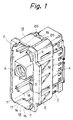
- a connector body 1 shown in FIGURE 1 comprises a rectangular hood 2 which receives a female connector not shown and a projected portion 4 which has a plurality of terminal-accommodating apertures 3 at its bottom.
- a lock member 5 shown in FIGURE 3 is attached to an attaching portion 13 of the hood 2.
- the lock member 5 is made of a sheet of thin steel plate.
- the hood 2 is provided on each corner on the mouth edge with a rib 11 which extends forwardly and on an entire periphery of the mouth with a flange 12. As described hereinafter, when the rib 11 is inserted into the attaching hole W in the panel P, the rib 11 serves to position the connector body 1 on the panel P and the flange 12 contacts with the rear side of the panel P.
- the hood 2 is provided on upper and lower faces with the attaching portion 13 which receives the lock member 5.
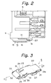
- the attaching portion 13 defines a rearward open flat clearance 16 by an inner wall 14 and an outer wall 15.
- the inner wall 14 which forms a part of an interior of the hood 2 is provided with an end face 17 cut at an intermediate portion in the hood 2 and a slit 18 extending forwardly along its center line.
- An engaging protrusion 19 is formed on the inner wall 14 in the clearance 16.
- Protrusions 20 are provided on opposite side walls at a proximal end in the clearance 16 so that the protrusions 20 make a width of the clearance 16 narrow, thereby preventing excessive insertion of the lock member into the clearance.
- the hood 2 is provided in the interior with a female screw portion 6 which engages with a male screw of the female connector not shown.
- the lock member 5 as shown in FIGURES 3 and 4, includes a center base plate 21, and an attaching piece 22 which is formed by folding an end of the plate 21 inwardly at a turning portion 21a.
- the lock member 5 can be inserted into the clearance 16 while deflecting the turning portion 21a.
- the lock member 5 also includes a locking arm 25 parallel to the base plate 21.
- the locking arm 25 has a first bend portion 23 bent inwardly at the other end of the base plate 21 by an angle of about 135° and a second bend portion 24 bent outwardly at an end of the first bend portion 23 by an angle of about 135°.
- the first and second bend portions 23 and 24 are provided with reinforcing protrusions 31 by punching, thereby maintaining the angles of the portions 23 and 24.
- the lock member 5 has a thickness t (FIGURE 5) equal to a gap of the clearance 16 plus a thickness of the inner wall 14 so that the lock member 5 can be inserted into the clearance 16.
- a contacting piece 26 (FIGURE 4) is formed by bending inwardly an end of the attaching piece 22 so that the piece 26 can contact with the rear side of the base plate 21 by means of deflection at the turning portion 21a upon inserting the member 5. That is, when the contacting piece 26 abuts on the base plate 21, the base plate 21, turning portion 21a, attaching piece 22, and contacting piece 26 define an O-shaped space having a thickness equal to the thickness t of the lock member, thereby restraining an excessive deflection of the turning portion 21a, when a large force such as a force necessary to insert the lock member 5 into the clearance 16 is applied to the attaching piece 22, the contacting piece 26 can be deflected.
- An engaging aperture 30 is formed in a center of the attaching piece 22 so that the engaging protrusion 19 engages with the aperture 30 upon inserting the lock member 5 into the clearance 16, thereby securing the lock member 5 in the clearance 16.
- the attaching piece 22 is provided on opposite sides with resisting pieces 27 which are bent outwardly and serve to prevent an excessive insertion of the lock member 5. The resisting pieces 27 contact with the protrusions 20 so as to restrain the excessive insertion of the lock member 5 when it is inserted into the clearance 16.
- the locking arm 25 is provided at an end with a triangular pawl 32 bent outwardly.
- the pawl has a slant face 33 which inclines rearwardly and a vertical face 34 perpendicular to the locking arm 25.
- the slant face 33 slides on the edge of the hole W while deflecting the locking arm 25, thereby enabling the lock member 5 to be inserted into the hole W.
- the vertical face 34 engages with the edge of the hole W by an elastic force of the locking arm.
- the locking arm 25 is provided on the opposite sides with outer limit pieces 35, ends of which extend to the same plane as the outer face of the base plate 21.
- the attaching piece 22 of the lock member 5 is inserted into the clearance 16. Then, the turning portion 21a is inserted into the clearance while deflecting and the contacting piece 26 slides over the engaging protrusion 19 while deflecting, even if the piece 26 abuts on the protrusion 19. As shown in FIGURE 6, the engaging protrusion 19 engages with the engaging aperture 30, the resisting protrusions 27 abuts on the protrusion 20, and the lock member 5 is held at this position in the clearance 16.
- the base plate 21 When attaching the lock member 5 in the clearance 16, the base plate 21 is pushed onto the outer wall by means of a spring action of the turning portion 21a and the locking arm 25 is arranged in parallel with the base plate 21. Since the thickness t of the lock member 5 is equal to the gap of the clearance 16 plus the thickness of the inner wall 14, the locking arm 25 is fixed on the panel without projecting into the hood 2 and does not interfere an insertion of the female connector not shown when it is inserted into the hood 2.
- the outer limit piece 35 is provided in this embodiment and the locking arm 25 is prevented from deflecting outwardly by means of the outer wall 15, there is no problem in which the locking arm 25 is outwardly deflected to a position shown by a two-dot chain line in FIGURE 7 so that an end of the pawl 32 abuts on the peripheral edge of the attaching hole W when attaching the lock member 5 to the panel P, thereby enabling the member 5 not to be inserted into the clearance 16. Accordingly, the lock member 5 is attached to the panel P with the slant face 33 always abutting on the edge E.
- first and second bend portions 23 and 24 are reinforced by projections 31 so that the locking arm 25 is not deflected inwardly and the pawl 32 does not lose a sufficient force to engage with the panel P, the locking arm 25 is secured to the panel P in parallel with the base plate 21.
- the connector body 1 is positioned so that the ribs 11 (FIGURE 1) on the mouth edge of the hood 2 can be inserted into the attaching hole W from the rear side of the panel P and the body 1 is pushed into the hole W until the flange 12 contacts with the rear side of the panel P.
- the locking arm 25 is inserted into the hole W while the slant face 33 of the pawl 32 slides on the mouth edge of the attaching hole W and the mouth edge deflects the arm 25.
- An elastic force of the locking arm 25 pushes the vertical face 34 onto the front side of the panel P and the flange 12 (FIGURE 1) and the vertical face 34 clamp the panel P at its front and rear sides.
- the base plate 21 does not loosen in the clearance 16.
- the contacting piece 26 abuts on the base plate 21, the locking arm 25 deflects from a contact point of the contacting piece on the base plate 21 and the lock member 5 is secured to the attaching portion 13 without loosening the member 5 therein. This can obtain a larger elastic force than a construction in which the turning portion 21a is a supporting point.
- the connector After attaching the connector to the attaching hole W, the connector is hardly detached from the attaching hole W and is steadily secured to the hole W by the following reasons even if any external force is applied to the pawl 32 to inwardly deflect the pawl 32:
- the lock member 5 is made of a sheet of thin steel plate in the above embodiment, although the lock member 5 is separated from the connector body 1, the lock member 5 can be easily formed.
- the lock protrusion 19 engages with the engaging aperture 30 so as to attach the lock member 5 to the attaching portion 13 merely by pushing the member 5 to the portion 13. Further, it is possible to attach the connector to the panel P merely by pushing the connector into the attaching hole W and to generate a force large enough to hold the connector in the attaching hole W.
- the lock member 5 is made of a sheet of thin steel plate in the above embodiment, it may be made of a hard plastic material.
- the connector body 1 is provided on both sides with the lock member 5 in the above embodiment, a rigid pawl is formed together on one side of the connector body 1 and the lock member 5 is formed on the other side of the body 1.
- the present invention should not be limited to the above embodiment and can be carried out within a scope without changing the gist of the invention.
Landscapes
- Details Of Connecting Devices For Male And Female Coupling (AREA)
- Connector Housings Or Holding Contact Members (AREA)
- Insertion Pins And Rivets (AREA)
Abstract
Description
- This invention relates to a panel-fixed type connector which is secured to an attaching hole formed in a panel.
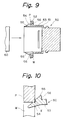
- For convenience of explanation, a conventional panel-fixed type connector will be explained below by referring to FIGURES 9 and 10. FIGURE 9 is a longitudinal sectional view of a part of the prior panel-fixed type connector and FIGURE 10 is an explanatory view illustrating a problem in the prior connector. As shown in FIGURE 9, some of the prior panel-fixed type connectors are made of a plastic material.
- A
connector 50 shown in the drawings is a male connector or a so-called door-waiting connector which is secured to a panel P on a car body side or a door side in an automobile. Theconnector 50 is provided with ahood 51 which receives afemale connector 60. Thehood 51 is provided around a mouth edge with aflange 52. When an end of thehood 51 is inserted into an attaching hole W in the panel P, theflange 52 contacts with a peripheral edge of the hole W. - Also, the
hood 51 is provided on an upper portion and a lower portion with aresilient locking arm 53 which has apawl 54 at its distal end. When the end of thehood 51 is inserted into the attaching hole W, thelocking arm 53 is inserted into the hole W while being deflected and thepawl 54 engages with the peripheral edge of the hole W. Thus, theconnector 50 is secured to the panel P by a clamping action of thepawl 54 andflange 52. Thepawl 54 has aslant face 55 which raises outwardly and rearwardly and avertical face 56 which extends in parallel with theflange 52. - However, since the attaching hole W in the panel P is formed by a punching work, the mouth edge will become sharp and be provided with a burr. Consequently, upon attaching the connector to the panel, as shown in FIGURE 10, the
slant face 55 on thepawl 54 is damaged by the sharp edge E and thepawl 54 can not be readily engaged with the hole W. - Although the attaching hole W may be smoothly worked in order to overcome the problem, a working cost will be high. Further, in the case of forming the
slant face 55 of the connector from a hard material such as a metal, the connector will become complicated in construction, large in size, and high in cost. - An object of the present invention is to provide a panel-fixed type connector which can overcome various problems caused by a slant face thereof made of a hard material.
- In order to achieve the above object, a panel-fixed type connector of the present invention which mounts a hood of a connector body on an attaching hole in a panel, is characterized in that the hood is provided around a mouth edge thereof with an attaching portion for supporting a lock member made of a hard material; and the lock member includes a base plate, an attaching piece provided on an end of the base plate and adapted to be secured to the attaching portion, and a resilient locking arm having a pawl to be engaged with the attaching hole.
- In the panel-fixed type connector, the attaching portion on the hood is formed by a clearance for receiving the base plate of the lock member and a lock protrusion in the clearance. The attaching piece of the lock member is folded on the base plate so as to be inserted into the clearance. An engaging aperture is formed in said attaching piece to receive the lock protrusion.
- The attaching piece is provided with a contacting end which is directed to the base plate so that the end contacts with the plate. Thus, even if the locking arm is deflected by an external force, the lock member does not loosen in the clearance. A first bend portion which is folded inwardly at an obtuse angle and a second bend portion which is folded outwardly at an obtuse angle are formed between the base plate of the lock member and the locking arm. The locking arm is arranged in parallel with the base plate. Thus, the pawl on the locking arm does not extend outwardly from the base plate.
- The locking arm of the lock member is provided with an outer limit piece which contacts with the attaching portion so that the outer limit piece restrains the arm from inclining outwardly.
- It will be apparent from the foregoing that the panel-fixed connector of the present invention has a simple construction and the hood thereof can be easily attached to the panel since the lock member having the pawl to be engaged with the attaching hole in the panel is secured to the attaching portion formed around the mouth edge of the hood.
- FIGURE 1 is a perspective view of a connector body of a panel-fixed type connector of the present invention;
- FIGURE 2 is a longitudinal sectional view of a part of the connector body shown in FIGURE 1;
- FIGURE 3 is a perspective view of a lock member to be used in the connector of the present invention;
- FIGURE 4 is a perspective view taken from a rear side of the lock member shown in FIGURE 3;
- FIGURE 5 is a longitudinal sectional view taken along lines V - V in FIGURE 3;
- FIGURE 6 is a fragmentary longitudinal sectional view of the connector, illustrating the lock member accommodated in the connector body;
- FIGURE 7 is a similar view to FIGURE 6, but illustrating the lock member being restrained from its movement;
- FIGURE 8 is another similar view to FIGURE 6, but illustrating the lock member being restrained from its movement;
- FIGURE 9 is a longitudinal sectional view of a part of a conventional panel-fixed type connector; and
- FIGURE 10 is an explanatory view illustrating a problem in the connector shown in FIGURE 9.
- By referring to FIGURES 1 to 8, an embodiment of a panel-fixed type connector in accordance with the present invention will be explained below. The panel-fixed type connector is a male connector. A
connector body 1 shown in FIGURE 1 comprises arectangular hood 2 which receives a female connector not shown and a projectedportion 4 which has a plurality of terminal-accommodating apertures 3 at its bottom. Alock member 5 shown in FIGURE 3 is attached to an attachingportion 13 of thehood 2. In this embodiment, thelock member 5 is made of a sheet of thin steel plate. - As shown in FIGURES 1 and 2, the
hood 2 is provided on each corner on the mouth edge with arib 11 which extends forwardly and on an entire periphery of the mouth with aflange 12. As described hereinafter, when therib 11 is inserted into the attaching hole W in the panel P, therib 11 serves to position theconnector body 1 on the panel P and theflange 12 contacts with the rear side of the panel P. - Also, the
hood 2 is provided on upper and lower faces with the attachingportion 13 which receives thelock member 5. The attachingportion 13 defines a rearward openflat clearance 16 by aninner wall 14 and anouter wall 15. Theinner wall 14 which forms a part of an interior of thehood 2 is provided with anend face 17 cut at an intermediate portion in thehood 2 and aslit 18 extending forwardly along its center line. Anengaging protrusion 19 is formed on theinner wall 14 in theclearance 16.Protrusions 20 are provided on opposite side walls at a proximal end in theclearance 16 so that theprotrusions 20 make a width of theclearance 16 narrow, thereby preventing excessive insertion of the lock member into the clearance. Thehood 2 is provided in the interior with afemale screw portion 6 which engages with a male screw of the female connector not shown. - The
lock member 5, as shown in FIGURES 3 and 4, includes acenter base plate 21, and an attachingpiece 22 which is formed by folding an end of theplate 21 inwardly at aturning portion 21a. Thelock member 5 can be inserted into theclearance 16 while deflecting theturning portion 21a. Thelock member 5 also includes alocking arm 25 parallel to thebase plate 21. Thelocking arm 25 has afirst bend portion 23 bent inwardly at the other end of thebase plate 21 by an angle of about 135° and asecond bend portion 24 bent outwardly at an end of thefirst bend portion 23 by an angle of about 135°. The first andsecond bend portions protrusions 31 by punching, thereby maintaining the angles of theportions lock member 5 has a thickness t (FIGURE 5) equal to a gap of theclearance 16 plus a thickness of theinner wall 14 so that thelock member 5 can be inserted into theclearance 16. - A contacting piece 26 (FIGURE 4) is formed by bending inwardly an end of the attaching
piece 22 so that thepiece 26 can contact with the rear side of thebase plate 21 by means of deflection at theturning portion 21a upon inserting themember 5. That is, when the contactingpiece 26 abuts on thebase plate 21, thebase plate 21, turningportion 21a, attachingpiece 22, and contactingpiece 26 define an O-shaped space having a thickness equal to the thickness t of the lock member, thereby restraining an excessive deflection of theturning portion 21a, when a large force such as a force necessary to insert thelock member 5 into theclearance 16 is applied to the attachingpiece 22, the contactingpiece 26 can be deflected. Anengaging aperture 30 is formed in a center of the attachingpiece 22 so that theengaging protrusion 19 engages with theaperture 30 upon inserting thelock member 5 into theclearance 16, thereby securing thelock member 5 in theclearance 16. Further, the attachingpiece 22 is provided on opposite sides with resistingpieces 27 which are bent outwardly and serve to prevent an excessive insertion of thelock member 5. The resistingpieces 27 contact with theprotrusions 20 so as to restrain the excessive insertion of thelock member 5 when it is inserted into theclearance 16. - On the other hand, the
locking arm 25 is provided at an end with atriangular pawl 32 bent outwardly. The pawl has aslant face 33 which inclines rearwardly and avertical face 34 perpendicular to thelocking arm 25. When thelock member 5 is inserted into the attaching hole W in the panel P, theslant face 33 slides on the edge of the hole W while deflecting thelocking arm 25, thereby enabling thelock member 5 to be inserted into the hole W. After inserting, thevertical face 34 engages with the edge of the hole W by an elastic force of the locking arm. Thelocking arm 25 is provided on the opposite sides withouter limit pieces 35, ends of which extend to the same plane as the outer face of thebase plate 21. - Next, an operation of the embodiment constructed above will be explained below.
- In order to attach the lock member to the
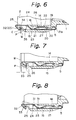
connector body 1, as shown in FIGURE 6, the attachingpiece 22 of thelock member 5 is inserted into theclearance 16. Then, the turningportion 21a is inserted into the clearance while deflecting and the contactingpiece 26 slides over the engagingprotrusion 19 while deflecting, even if thepiece 26 abuts on theprotrusion 19. As shown in FIGURE 6, the engagingprotrusion 19 engages with the engagingaperture 30, the resistingprotrusions 27 abuts on theprotrusion 20, and thelock member 5 is held at this position in theclearance 16. - When attaching the
lock member 5 in theclearance 16, thebase plate 21 is pushed onto the outer wall by means of a spring action of the turningportion 21a and the lockingarm 25 is arranged in parallel with thebase plate 21. Since the thickness t of thelock member 5 is equal to the gap of theclearance 16 plus the thickness of theinner wall 14, the lockingarm 25 is fixed on the panel without projecting into thehood 2 and does not interfere an insertion of the female connector not shown when it is inserted into thehood 2. - Also, since the
outer limit piece 35 is provided in this embodiment and the lockingarm 25 is prevented from deflecting outwardly by means of theouter wall 15, there is no problem in which thelocking arm 25 is outwardly deflected to a position shown by a two-dot chain line in FIGURE 7 so that an end of thepawl 32 abuts on the peripheral edge of the attaching hole W when attaching thelock member 5 to the panel P, thereby enabling themember 5 not to be inserted into theclearance 16. Accordingly, thelock member 5 is attached to the panel P with theslant face 33 always abutting on the edge E. - Adversely, since the first and
second bend portions projections 31 so that the lockingarm 25 is not deflected inwardly and thepawl 32 does not lose a sufficient force to engage with the panel P, the lockingarm 25 is secured to the panel P in parallel with thebase plate 21. - Thus, in order to attach the
connector body 1 which accommodates thelock member 5 to the attaching hole W, theconnector body 1 is positioned so that the ribs 11 (FIGURE 1) on the mouth edge of thehood 2 can be inserted into the attaching hole W from the rear side of the panel P and thebody 1 is pushed into the hole W until theflange 12 contacts with the rear side of the panel P. Then, as shown in FIGURE 6, the lockingarm 25 is inserted into the hole W while theslant face 33 of thepawl 32 slides on the mouth edge of the attaching hole W and the mouth edge deflects thearm 25. An elastic force of the lockingarm 25 pushes thevertical face 34 onto the front side of the panel P and the flange 12 (FIGURE 1) and thevertical face 34 clamp the panel P at its front and rear sides. - When the
pawl 32 is inserted into the attaching hole W, a rearward force is applied to theslant face 33, thereby applying a vertical component of force to thelock member 5. Consequently, thelock member 5 is further pushed into theclearance 16, but the lock member is not inserted excessively into theclearance 16 but held at a given position in the clearance by an engagement of theprotrusions - Since the vertical component of force deflects inwardly not only the locking
arm 25 but also thebase plate 21 from the turningportion 21a, thebase plate 21 does not loosen in theclearance 16. However, since the contactingpiece 26 abuts on thebase plate 21, the lockingarm 25 deflects from a contact point of the contacting piece on thebase plate 21 and thelock member 5 is secured to the attachingportion 13 without loosening themember 5 therein. This can obtain a larger elastic force than a construction in which the turningportion 21a is a supporting point. - After attaching the connector to the attaching hole W, the connector is hardly detached from the attaching hole W and is steadily secured to the hole W by the following reasons even if any external force is applied to the
pawl 32 to inwardly deflect the pawl 32: - (1) a force caused by a spring action of the turning
portion 21a pushes thebase plate 21 onto theouter wall 15; - (2) a stiffness of the locking
arm 25 is enhanced by the reinforcingprojection 31; and - (3) the contacting
piece 26 supports thebase plate 21 when the lockingarm 25 deflects inwardly. - As described above, since the
lock member 5 is made of a sheet of thin steel plate in the above embodiment, although thelock member 5 is separated from theconnector body 1, thelock member 5 can be easily formed. Thelock protrusion 19 engages with the engagingaperture 30 so as to attach thelock member 5 to the attachingportion 13 merely by pushing themember 5 to theportion 13. Further, it is possible to attach the connector to the panel P merely by pushing the connector into the attaching hole W and to generate a force large enough to hold the connector in the attaching hole W. - Although the
lock member 5 is made of a sheet of thin steel plate in the above embodiment, it may be made of a hard plastic material. - Although the
connector body 1 is provided on both sides with thelock member 5 in the above embodiment, a rigid pawl is formed together on one side of theconnector body 1 and thelock member 5 is formed on the other side of thebody 1. The present invention should not be limited to the above embodiment and can be carried out within a scope without changing the gist of the invention.
Claims (5)
- A panel-fixed type connector which mounts a hood of a connector body on an attaching hole in a panel,
characterized in that:
said hood is provided around a mouth edge thereof with an attaching portion for supporting a lock member made of a hard material; and
said lock member includes a base plate, an attaching piece provided on an end of said base plate and adapted to be secured to said attaching portion, and a resilient locking arm having a pawl to be engaged with said attaching hole. - A panel-fixed type connector according to Claim 1, wherein said attaching portion on said hood is formed by a clearance for receiving said base plate of said lock member and a lock protrusion in said clearance, wherein said attaching piece of said lock member is folded on said base plate so as to be inserted into said clearance, and wherein an engaging aperture is formed in said attaching piece to receive said lock protrusion.
- A panel-fixed type connector according to Claim 2, wherein said attaching piece is provided with a contacting end which is directed to said base plate so that said end contacts with said plate.
- A panel-fixed type connector according to Claim 1, wherein a first bend portion which is folded inwardly at an obtuse angle and a second bend portion which is folded outwardly at an obtuse angle are formed between said base plate of said lock member and said locking arm, and wherein said locking arm is arranged in parallel with said base plate.
- A panel-fixed type connector according to Claim 1, wherein said locking arm of said lock member is provided with an outer limit piece which contacts with said attaching portion so that said outer limit piece restrains said arm from inclining outwardly.
Applications Claiming Priority (2)
| Application Number | Priority Date | Filing Date | Title |
|---|---|---|---|
| JP10916/93 | 1993-02-17 | ||
| JP1993010916U JP2567856Y2 (en) | 1993-02-17 | 1993-02-17 | Panel mounting connector |
Publications (3)
| Publication Number | Publication Date |
|---|---|
| EP0611867A2 true EP0611867A2 (en) | 1994-08-24 |
| EP0611867A3 EP0611867A3 (en) | 1995-03-22 |
| EP0611867B1 EP0611867B1 (en) | 1998-01-07 |
Family
ID=11763585
Family Applications (1)
| Application Number | Title | Priority Date | Filing Date |
|---|---|---|---|
| EP94301147A Expired - Lifetime EP0611867B1 (en) | 1993-02-17 | 1994-02-17 | Panel-fixed type connector |
Country Status (4)
| Country | Link |
|---|---|
| US (1) | US5435749A (en) |
| EP (1) | EP0611867B1 (en) |
| JP (1) | JP2567856Y2 (en) |
| DE (1) | DE69407632T2 (en) |
Cited By (2)
| Publication number | Priority date | Publication date | Assignee | Title |
|---|---|---|---|---|
| EP0913891A3 (en) * | 1997-10-01 | 2000-06-28 | Sumitomo Wiring Systems, Ltd. | Electrical connector |
| FR2947963A1 (en) * | 2009-07-13 | 2011-01-14 | Peugeot Citroen Automobiles Sa | ELECTRICAL CONNECTION DEVICE REPORTED FOR A VEHICLE ELEMENT |
Families Citing this family (4)
| Publication number | Priority date | Publication date | Assignee | Title |
|---|---|---|---|---|
| JP3384468B2 (en) * | 1994-06-22 | 2003-03-10 | タイコエレクトロニクスアンプ株式会社 | Panel mounting connector |
| USD437829S1 (en) | 1999-11-30 | 2001-02-20 | Omron Corporation | Connector |
| JP2006073479A (en) * | 2004-09-06 | 2006-03-16 | Yazaki Corp | Panel feed-through connector |
| US12413008B2 (en) * | 2021-04-12 | 2025-09-09 | Te Connectivity Solutions Gmbh | Temporary header retention feature |
Family Cites Families (5)
| Publication number | Priority date | Publication date | Assignee | Title |
|---|---|---|---|---|
| FR2315821A1 (en) * | 1975-06-25 | 1977-01-21 | Socotel | Rear support frame mounting for electronic modules - uses two clips and two forks to hold female connector attached to module |
| US4609119A (en) * | 1985-08-28 | 1986-09-02 | Heinemann Electric Company | Retaining device for mounting electrical units |
| US4621885A (en) * | 1985-09-20 | 1986-11-11 | Amp Incorporated | Ribbon cable connector with improved cover latch |
| JPS62184677A (en) * | 1986-02-08 | 1987-08-13 | Sony Corp | Tape cassette |
| JPH02143785A (en) * | 1988-11-25 | 1990-06-01 | Matsushita Electric Ind Co Ltd | Phase comparator circuit and phase synchronizing circuit |
-
1993
- 1993-02-17 JP JP1993010916U patent/JP2567856Y2/en not_active Expired - Lifetime
-
1994
- 1994-02-15 US US08/196,421 patent/US5435749A/en not_active Expired - Lifetime
- 1994-02-17 EP EP94301147A patent/EP0611867B1/en not_active Expired - Lifetime
- 1994-02-17 DE DE69407632T patent/DE69407632T2/en not_active Expired - Lifetime
Cited By (6)
| Publication number | Priority date | Publication date | Assignee | Title |
|---|---|---|---|---|
| EP0913891A3 (en) * | 1997-10-01 | 2000-06-28 | Sumitomo Wiring Systems, Ltd. | Electrical connector |
| US6183275B1 (en) | 1997-10-01 | 2001-02-06 | Sumitomo Wiring Systems, Ltd. | Panel mounted lever connector |
| FR2947963A1 (en) * | 2009-07-13 | 2011-01-14 | Peugeot Citroen Automobiles Sa | ELECTRICAL CONNECTION DEVICE REPORTED FOR A VEHICLE ELEMENT |
| WO2011007068A1 (en) | 2009-07-13 | 2011-01-20 | Peugeot Citroën Automobiles SA | Additional electrical connection device for a vehicle element |
| CN102474045A (en) * | 2009-07-13 | 2012-05-23 | 标致·雪铁龙汽车公司 | Additional electrical connection device for a vehicle element |
| CN102474045B (en) * | 2009-07-13 | 2014-08-13 | 标致·雪铁龙汽车公司 | Additional electrical connection device for a vehicle element |
Also Published As
| Publication number | Publication date |
|---|---|
| DE69407632T2 (en) | 1998-05-28 |
| EP0611867A3 (en) | 1995-03-22 |
| US5435749A (en) | 1995-07-25 |
| DE69407632D1 (en) | 1998-02-12 |
| JPH0664382U (en) | 1994-09-09 |
| EP0611867B1 (en) | 1998-01-07 |
| JP2567856Y2 (en) | 1998-04-08 |
Similar Documents
| Publication | Publication Date | Title |
|---|---|---|
| US5480312A (en) | Protecting cap for panel-mounted electrical connector | |
| EP0883213A2 (en) | Connector | |
| JPH0734569U (en) | connector | |
| EP0615315B1 (en) | Panel-mounted electrical connector | |
| US5803758A (en) | Switch box mounting structure | |
| US4947290A (en) | Rail mounting device for an electrical equipment | |
| EP0611867B1 (en) | Panel-fixed type connector | |
| JP3168396B2 (en) | Connector with rear holder | |
| US7128601B2 (en) | Wire cover for connectors | |
| EP0572021B1 (en) | Body mounting type electrical connector | |
| EP0940883B1 (en) | Connector retaining construction | |
| JP2555394Y2 (en) | connector | |
| US6196884B1 (en) | Female metal terminal that stably connects with male metal terminal | |
| JPH07226251A (en) | Lock type connector | |
| EP1585199B1 (en) | A connector and a terminal fitting | |
| JP3650793B2 (en) | Connector mounting clamp | |
| JP2956501B2 (en) | Structure for fixing plate-like articles in the case | |
| JPH09219235A (en) | Male connector | |
| JPH087971A (en) | Connector for circuit board | |
| JP3612926B2 (en) | connector | |
| JP3286195B2 (en) | Locking structure of front holder to housing | |
| JPH0711745U (en) | Fuse locking structure | |
| US6468115B2 (en) | Terminal retainer-attached connector | |
| JP2574800Y2 (en) | Joint connector | |
| JPH09134762A (en) | Panel fixing connector |
Legal Events
| Date | Code | Title | Description |
|---|---|---|---|
| PUAI | Public reference made under article 153(3) epc to a published international application that has entered the european phase |
Free format text: ORIGINAL CODE: 0009012 |
|
| 17P | Request for examination filed |
Effective date: 19940302 |
|
| AK | Designated contracting states |
Kind code of ref document: A2 Designated state(s): DE GB |
|
| PUAL | Search report despatched |
Free format text: ORIGINAL CODE: 0009013 |
|
| AK | Designated contracting states |
Kind code of ref document: A3 Designated state(s): DE GB |
|
| 17Q | First examination report despatched |
Effective date: 19960419 |
|
| GRAG | Despatch of communication of intention to grant |
Free format text: ORIGINAL CODE: EPIDOS AGRA |
|
| GRAG | Despatch of communication of intention to grant |
Free format text: ORIGINAL CODE: EPIDOS AGRA |
|
| GRAH | Despatch of communication of intention to grant a patent |
Free format text: ORIGINAL CODE: EPIDOS IGRA |
|
| GRAH | Despatch of communication of intention to grant a patent |
Free format text: ORIGINAL CODE: EPIDOS IGRA |
|
| GRAA | (expected) grant |
Free format text: ORIGINAL CODE: 0009210 |
|
| AK | Designated contracting states |
Kind code of ref document: B1 Designated state(s): DE GB |
|
| REF | Corresponds to: |
Ref document number: 69407632 Country of ref document: DE Date of ref document: 19980212 |
|
| PLBE | No opposition filed within time limit |
Free format text: ORIGINAL CODE: 0009261 |
|
| STAA | Information on the status of an ep patent application or granted ep patent |
Free format text: STATUS: NO OPPOSITION FILED WITHIN TIME LIMIT |
|
| 26N | No opposition filed | ||
| REG | Reference to a national code |
Ref country code: GB Ref legal event code: IF02 |
|
| PGFP | Annual fee paid to national office [announced via postgrant information from national office to epo] |
Ref country code: GB Payment date: 20110216 Year of fee payment: 18 |
|
| GBPC | Gb: european patent ceased through non-payment of renewal fee |
Effective date: 20120217 |
|
| PG25 | Lapsed in a contracting state [announced via postgrant information from national office to epo] |
Ref country code: GB Free format text: LAPSE BECAUSE OF NON-PAYMENT OF DUE FEES Effective date: 20120217 |
|
| PGFP | Annual fee paid to national office [announced via postgrant information from national office to epo] |
Ref country code: DE Payment date: 20130213 Year of fee payment: 20 |
|
| REG | Reference to a national code |
Ref country code: DE Ref legal event code: R071 Ref document number: 69407632 Country of ref document: DE |
|
| PG25 | Lapsed in a contracting state [announced via postgrant information from national office to epo] |
Ref country code: DE Free format text: LAPSE BECAUSE OF EXPIRATION OF PROTECTION Effective date: 20140218 |