EP0611440B1 - Inductive angular displacement sensor - Google Patents
Inductive angular displacement sensor Download PDFInfo
- Publication number
- EP0611440B1 EP0611440B1 EP92922286A EP92922286A EP0611440B1 EP 0611440 B1 EP0611440 B1 EP 0611440B1 EP 92922286 A EP92922286 A EP 92922286A EP 92922286 A EP92922286 A EP 92922286A EP 0611440 B1 EP0611440 B1 EP 0611440B1
- Authority
- EP
- European Patent Office
- Prior art keywords
- poles
- component
- sensor according
- coils
- ferromagnetic
- Prior art date
- Legal status (The legal status is an assumption and is not a legal conclusion. Google has not performed a legal analysis and makes no representation as to the accuracy of the status listed.)
- Expired - Lifetime
Links
- 238000006073 displacement reaction Methods 0.000 title claims abstract description 9
- 230000001939 inductive effect Effects 0.000 title description 2
- 238000004804 winding Methods 0.000 claims abstract description 18
- 230000005284 excitation Effects 0.000 claims abstract description 10
- 230000005294 ferromagnetic effect Effects 0.000 claims description 13
- 238000012216 screening Methods 0.000 claims description 12
- 239000003302 ferromagnetic material Substances 0.000 claims description 5
- 239000000463 material Substances 0.000 claims description 5
- 238000010079 rubber tapping Methods 0.000 claims 1
- 230000004907 flux Effects 0.000 abstract description 10
- 230000008878 coupling Effects 0.000 description 8
- 238000010168 coupling process Methods 0.000 description 8
- 238000005859 coupling reaction Methods 0.000 description 8
- 230000035945 sensitivity Effects 0.000 description 5
- 230000001965 increasing effect Effects 0.000 description 4
- 230000005291 magnetic effect Effects 0.000 description 4
- 238000013461 design Methods 0.000 description 3
- 229910052751 metal Inorganic materials 0.000 description 3
- 239000002184 metal Substances 0.000 description 3
- 230000008859 change Effects 0.000 description 2
- 230000003247 decreasing effect Effects 0.000 description 2
- 238000004519 manufacturing process Methods 0.000 description 2
- 230000035699 permeability Effects 0.000 description 2
- 238000012545 processing Methods 0.000 description 2
- 238000012546 transfer Methods 0.000 description 2
- CWYNVVGOOAEACU-UHFFFAOYSA-N Fe2+ Chemical compound [Fe+2] CWYNVVGOOAEACU-UHFFFAOYSA-N 0.000 description 1
- 230000006978 adaptation Effects 0.000 description 1
- 239000004411 aluminium Substances 0.000 description 1
- 229910052782 aluminium Inorganic materials 0.000 description 1
- XAGFODPZIPBFFR-UHFFFAOYSA-N aluminium Chemical compound [Al] XAGFODPZIPBFFR-UHFFFAOYSA-N 0.000 description 1
- 230000008901 benefit Effects 0.000 description 1
- 239000004020 conductor Substances 0.000 description 1
- 238000010276 construction Methods 0.000 description 1
- 238000010586 diagram Methods 0.000 description 1
- 230000000694 effects Effects 0.000 description 1
- 238000010348 incorporation Methods 0.000 description 1
- 230000007246 mechanism Effects 0.000 description 1
- 238000000034 method Methods 0.000 description 1
- 230000001360 synchronised effect Effects 0.000 description 1
- 229910000859 α-Fe Inorganic materials 0.000 description 1
Images




Classifications
-
- G—PHYSICS
- G01—MEASURING; TESTING
- G01D—MEASURING NOT SPECIALLY ADAPTED FOR A SPECIFIC VARIABLE; ARRANGEMENTS FOR MEASURING TWO OR MORE VARIABLES NOT COVERED IN A SINGLE OTHER SUBCLASS; TARIFF METERING APPARATUS; MEASURING OR TESTING NOT OTHERWISE PROVIDED FOR
- G01D5/00—Mechanical means for transferring the output of a sensing member; Means for converting the output of a sensing member to another variable where the form or nature of the sensing member does not constrain the means for converting; Transducers not specially adapted for a specific variable
- G01D5/12—Mechanical means for transferring the output of a sensing member; Means for converting the output of a sensing member to another variable where the form or nature of the sensing member does not constrain the means for converting; Transducers not specially adapted for a specific variable using electric or magnetic means
- G01D5/14—Mechanical means for transferring the output of a sensing member; Means for converting the output of a sensing member to another variable where the form or nature of the sensing member does not constrain the means for converting; Transducers not specially adapted for a specific variable using electric or magnetic means influencing the magnitude of a current or voltage
- G01D5/20—Mechanical means for transferring the output of a sensing member; Means for converting the output of a sensing member to another variable where the form or nature of the sensing member does not constrain the means for converting; Transducers not specially adapted for a specific variable using electric or magnetic means influencing the magnitude of a current or voltage by varying inductance, e.g. by a movable armature
- G01D5/22—Mechanical means for transferring the output of a sensing member; Means for converting the output of a sensing member to another variable where the form or nature of the sensing member does not constrain the means for converting; Transducers not specially adapted for a specific variable using electric or magnetic means influencing the magnitude of a current or voltage by varying inductance, e.g. by a movable armature differentially influencing two coils
- G01D5/2208—Mechanical means for transferring the output of a sensing member; Means for converting the output of a sensing member to another variable where the form or nature of the sensing member does not constrain the means for converting; Transducers not specially adapted for a specific variable using electric or magnetic means influencing the magnitude of a current or voltage by varying inductance, e.g. by a movable armature differentially influencing two coils by influencing the self-induction of the coils
- G01D5/2216—Mechanical means for transferring the output of a sensing member; Means for converting the output of a sensing member to another variable where the form or nature of the sensing member does not constrain the means for converting; Transducers not specially adapted for a specific variable using electric or magnetic means influencing the magnitude of a current or voltage by varying inductance, e.g. by a movable armature differentially influencing two coils by influencing the self-induction of the coils by a movable ferromagnetic element, e.g. a core
-
- G—PHYSICS
- G01—MEASURING; TESTING
- G01D—MEASURING NOT SPECIALLY ADAPTED FOR A SPECIFIC VARIABLE; ARRANGEMENTS FOR MEASURING TWO OR MORE VARIABLES NOT COVERED IN A SINGLE OTHER SUBCLASS; TARIFF METERING APPARATUS; MEASURING OR TESTING NOT OTHERWISE PROVIDED FOR
- G01D5/00—Mechanical means for transferring the output of a sensing member; Means for converting the output of a sensing member to another variable where the form or nature of the sensing member does not constrain the means for converting; Transducers not specially adapted for a specific variable
- G01D5/12—Mechanical means for transferring the output of a sensing member; Means for converting the output of a sensing member to another variable where the form or nature of the sensing member does not constrain the means for converting; Transducers not specially adapted for a specific variable using electric or magnetic means
- G01D5/14—Mechanical means for transferring the output of a sensing member; Means for converting the output of a sensing member to another variable where the form or nature of the sensing member does not constrain the means for converting; Transducers not specially adapted for a specific variable using electric or magnetic means influencing the magnitude of a current or voltage
- G01D5/20—Mechanical means for transferring the output of a sensing member; Means for converting the output of a sensing member to another variable where the form or nature of the sensing member does not constrain the means for converting; Transducers not specially adapted for a specific variable using electric or magnetic means influencing the magnitude of a current or voltage by varying inductance, e.g. by a movable armature
- G01D5/2006—Mechanical means for transferring the output of a sensing member; Means for converting the output of a sensing member to another variable where the form or nature of the sensing member does not constrain the means for converting; Transducers not specially adapted for a specific variable using electric or magnetic means influencing the magnitude of a current or voltage by varying inductance, e.g. by a movable armature by influencing the self-induction of one or more coils
- G01D5/2013—Mechanical means for transferring the output of a sensing member; Means for converting the output of a sensing member to another variable where the form or nature of the sensing member does not constrain the means for converting; Transducers not specially adapted for a specific variable using electric or magnetic means influencing the magnitude of a current or voltage by varying inductance, e.g. by a movable armature by influencing the self-induction of one or more coils by a movable ferromagnetic element, e.g. a core
Definitions
- This invention relates to devices comprising angular displacement sensors.
- EP-A-0,460,417 (which is prior art only in terms of Article 54(3) EPC, not having been published until after the priority date of the present application) concerns a sensor device having a component with a pair of concentric walls whose height varies, so that the relative rotational position affects the inductance of two coils mounted on the other two of three radially-disposed poles of an E-shaped core.
- EP-A-0,049,987 concerns a sensor device employing a transformer having a primary winding wound on a central bobbin. Radially outwardly of this there are three secondary coils on cores. The flux circuit thus extends radially from a secondary coil to the central coil.
- DE-A-4,102,478 discloses a sensor device having only a single coil, which is wound on the central hub of a first component.
- a second component provides a sector-shaped element which rotates over the axial face of the first component.
- More complex devices with plural coils are basically produced by 'doubling up' the single coil embodiment.
- Inductive brushless angle sensing principles are described in our patent specifications WO88/06716 and WO90/04152.
- the present invention concerns their adaptation to provide angle sensing means suitable for use within a device such as a torque motor or vehicle throttle actuator, preferably requiring little or no extension to the housings of such mechanisms.
- Embodiments of the invention may enable one to achieve this with utmost economy in manufacturing cost and space envelope.
- WO-A-90/04152 discloses various homopolar devices, including some limited angle rotary sensors.
- One such device has a part-ferromagnetic rotor circumferentially surrounding a stator which is divided into poles by axial slots. Coils are wound on poles defined by pairs of slots.
- a device is an angular displacement sensor comprising first and second relatively rotatable components; the first said component providing a plurality of poles which are angularly disposed about the rotation axis and extend towards the second component, said poles constituting excitation poles and return path poles; said excitation poles carrying winding coils; said second component comprising an inductance affecting component which is constructed and arranged so as to overlie only some of the excitation poles at any given time, the relative rotation varying the poles which are overlaid; the sensor further including means for providing output signal data related to the inductances of the excitation poles and thus related to the rotary configuration of the components.
- the present invention provides such a device in which the first and second components confront each other axially, the poles extending parallel to the axis.
- Embodiments of the present invention are particularly suitable for a restricted angular range (which generally means substantially less than 360°, and usually 180° or less, particularly 120° or less).
- the sensor comprises first and second relatively rotatable components. (These will generally be a rotor for coupling to a rotatable element of a device such as a shaft, and a stator for coupling to a housing of the device). These components confront one another axially.
- One provides a plurality of axially extending poles arranged around at least part of a circle, suitably provided by an annular projection having gaps dividing it into discrete poles. Some (only) of the poles bear winding coils.
- a ferromagnetic element is axially adjacent the poles.
- the ferromagnetic element (if present) may be fixed relative to the first component but, interposed between the element and the first component, there is a screening element of non-magnetic conducting material which is rotatable relative to the first component and is shaped to overlie only some of the poles.
- the rotatable element may comprise a combination of ferromagnetic coupling and non-magnetic screening materials. In all cases, relative rotation leads to variation in inductance of the individual poles. By applying alternating voltages across them and detecting voltage drops, one can derive electrical output data related to angular displacement. The data can be processed and the results displayed in ways that will be apparent to the skilled reader.
- the axial construction enables simple, compact sensors to be produced, highly suitable for incorporation in rotary devices such as automotive throttle position sensors and torque motors.
- the invention provides a rotary device having a housing, a rotatable shaft extending within the housing, and an angular displacement sensor of the above type mounted at least partly within the housing, with one of said relatively rotatable components rotationally coupled to the shaft.
- the poles may be connected as a homopolar or heteropolar array.
- Fig. 1 shows a typical embodiment mounted to a device such as an actuator having a housing 10.
- the device has a shaft 12 which is carried by a journal bearing 13.
- a sensor stator 14 of ferromagnetic material such as a ferrite or ferroplastic is located concentric with the shaft 12 in a tubular extension 11' of the housing 11 which, if of metal such as aluminium, will provide electromagnetic shielding of the sensor.
- the axially inner surface of the stator 14 has an annular projection divided into three poles 14A, 14B and 14C, in this case of equal 120° span. Two of these (14A and 14B) carry coils 15 which are connected in series as shown in Fig. 1D to an a.c. supply Vs-Vo, an intermediate connection being brought out to a tap T.
- a rotor 16 is attached to the end of the shaft 12 by a screw or other suitable means, positioned so that it rotates close to the pole surfaces of the stator 14.
- Rotor 16 is an incomplete disc, having a 120° sector missing, except in the central hub portion 16a.
- stator 14 is of ferromagnetic material, so that it provides flux coupling between the stator poles, except for the 120° cutaway portion, shown exposing pole 14A. This therefore allows flux developed by the winding of pole 14B to pass freely through the high permeability path provided by the rotor and return to the unwound pole 14C, while flux developed in pole 14A has only a low permeability leakage path through air.
- the inductance of the winding at pole 14A will therefore be lower than that of pole 14B, so that the highest volt drop will be across the winding of pole 14B to centre tap T.
- Rotating the rotor by 120° clockwise will progressively transfer high inductance and volt-drop to pole 14A.
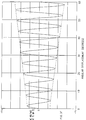
- the voltage between tap T and terminal Vo will then rise and fall as an analogue of shaft angle, as explained in the referenced patent applications, over a range of 120° (Fig. 2).
- Signal processing means 17 receive the voltage signals and provide an output signal indicative of angular displacement.
- Fig. 1 shows a stator with symmetrical pole arcs, this is not essential, though in general the two wound poles should be equal in span.
- the full angular range is the 120° span of the wound poles and corresponding cut-out in the rotor, but this range could be slightly increased by increasing the span of the wound poles and decreasing the unwound pole span.
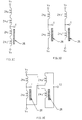
- the number of poles can be doubled, as exemplified in the embodiment of Figs. 3A to 3G, which has six poles of 60° span arranged as two diametrally opposite wound pairs 24D, 24D' and 24E, 24E', and an unwound pair 24F.
- Rotor 26 now has two diametrally opposite cut-outs of 60° span. In the position shown, poles 24D and 24D' are uncovered and thus have reduced winding inductance, while 60° rotation clockwise will transfer low inductance to poles 24E and 24E'. With series connection, the centre tap voltage level will be an analogue of 60° travel, but there are two ways of connecting the coils. For simple operation each opposed pair is series connected, giving an output of the form shown in Fig. 3F, analogous to the output shown in Fig. 2.
- pole 24D can be connected in series with 24E only across the supply, and pole 24D' can be similarly connected with pole 24E' across the same or a separate supply, thus giving two centre tap outputs of similar angular analogue form.
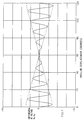
- Doubled sensitivity can be obtained by connecting the two sets of windings in Fig. 3D to produce a differential output between the taps, e.g. by reversing the supply connections to coils 24D and 24E', connection being as shown in Fig. 3E and resulting output in Fig. 3G, analogous to Fig. 3F.
- Phase reversal of the carrier voltage occurs at the mid-point of the angular span, necessitating the use of a synchronous demodulation circuit.
- the angular range of 60° can be modified if required by increasing or decreasing the span of the matched wound pole pairs.
- FIG. 1 A-D An alternative method of changing the inductance of a winding is to interpose a screen of high conductivity material such as non-ferrous metal in the flux path, as described in the referenced patent applications. This is equally applicable to this design. Referring back to Fig. 1 A-D, a screen of 120° span in place of the 120° cut-out over pole 14A would reduce its inductance. However, a much greater screening effect is obtainable if there is a ferromagnetic flux path on the other side of the screen, so that flux is forced to try and pass through the screen. Fig.
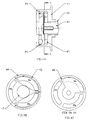
- FIG. 4 A-C shows a preferred arrangement of this type, in which the wound stator 44 is faced by a ferromagnetic backing ring 47, the 120° conducting screen rotor 48 being in the air-gap between them.
- Use of a rotor of the screening type as opposed to the ferromagnetic coupling type gives the designer options in optimising the performance of the sensor under varying specification conditions. For example, high supply frequencies may suit screening, while lower frequencies may be better served by ferromagnetic coupling.
- Figs. 3A to 3E the corresponding screening rotor would present two diametrically opposed blades of 60° span in place of the corresponding cut-outs over poles 24D and 24D'.
- the double-sided stator arrangement of Fig. 5 may be utilised.
- the stator 54 is duplicated each side of the rotor blade 58, which may be of ferromagnetic flux coupling material or of non-magnetic screening metal as required.
- This has the production advantage of using double the quantity of the same stator component, rather than two different ones like components 44 and 47 in Fig. 3.
- the stator windings are then arranged to produce flux in the same direction across the air-gap at any pole, making the sensor relatively tolerant of small axial location variations due to end-float of the shaft in its bearings.
- the coils on the two stator halves can be series connected as one auto-transformer, or as two separate auto-transformers to provide a duplicate or differential output for maximum sensitivity.
- the stator pole layout may be of any of the foregoing types.
- Winding 65 comprises coils 65A and 65B around poles 14A and 14B respectively.
- Coil 65A is bifilar wound to produce two windings 65A 1 and 65A 2 of identical turns and impedance, and 65B similarly divided into 65B 1 and 65B 2 .
- 65A 1 and 65B 1 are connected in series between supply terminals Vs and Vo as shown, with a centre tap T1.
- 65B 2 and 65A 2 are similarly series connected, with centre tap T2. It will be clear that reducing the inductance of 65A relative to 65B will cause the voltage level at T1 to rise towards Vs while the level at T2 falls towards Vo, and vice-versa, so that the change in output voltage per degree of rotation between taps T1 and T2 will be the sum of two as shown in Fig. 7, analogous to Fig. 3F.
- a disc-shaped stator of moulded ferromagnetic material with raised pole faces enables coils to be preformed, then fitted, connected and bonded or encapsulated in place.
- Termination may conveniently be made to a circuit board positioned as shown at 59 in Fig. 5.
- the Fig. 1 A-D design could be reversed to fit the stator 14 adjacent to the end wall for the housing 11 so that only rotor 16 projects, the terminations would then also have to be inboard, which may not be so convenient.
Landscapes
- Physics & Mathematics (AREA)
- General Physics & Mathematics (AREA)
- Transmission And Conversion Of Sensor Element Output (AREA)
- Measurement Of Length, Angles, Or The Like Using Electric Or Magnetic Means (AREA)
Abstract
Description
- This invention relates to devices comprising angular displacement sensors.
- EP-A-0,460,417 (which is prior art only in terms of Article 54(3) EPC, not having been published until after the priority date of the present application) concerns a sensor device having a component with a pair of concentric walls whose height varies, so that the relative rotational position affects the inductance of two coils mounted on the other two of three radially-disposed poles of an E-shaped core.
- EP-A-0,049,987 concerns a sensor device employing a transformer having a primary winding wound on a central bobbin. Radially outwardly of this there are three secondary coils on cores. The flux circuit thus extends radially from a secondary coil to the central coil.
- DE-A-4,102,478 discloses a sensor device having only a single coil, which is wound on the central hub of a first component. A second component provides a sector-shaped element which rotates over the axial face of the first component. More complex devices with plural coils are basically produced by 'doubling up' the single coil embodiment.
- Inductive brushless angle sensing principles are described in our patent specifications WO88/06716 and WO90/04152. The present invention concerns their adaptation to provide angle sensing means suitable for use within a device such as a torque motor or vehicle throttle actuator, preferably requiring little or no extension to the housings of such mechanisms.
- There are many applications in motion control systems in which shaft angle must be accurately measured and electrically transmitted. Embodiments of the invention may enable one to achieve this with utmost economy in manufacturing cost and space envelope.
- WO-A-90/04152 discloses various homopolar devices, including some limited angle rotary sensors. One such device has a part-ferromagnetic rotor circumferentially surrounding a stator which is divided into poles by axial slots. Coils are wound on poles defined by pairs of slots. Thus such a device is an angular displacement sensor comprising first and second relatively rotatable components; the first said component providing a plurality of poles which are angularly disposed about the rotation axis and extend towards the second component, said poles constituting excitation poles and return path poles; said excitation poles carrying winding coils; said second component comprising an inductance affecting component which is constructed and arranged so as to overlie only some of the excitation poles at any given time, the relative rotation varying the poles which are overlaid; the sensor further including means for providing output signal data related to the inductances of the excitation poles and thus related to the rotary configuration of the components.
- The present invention, as set out in
claim 1, provides such a device in which the first and second components confront each other axially, the poles extending parallel to the axis. - Embodiments of the present invention are particularly suitable for a restricted angular range (which generally means substantially less than 360°, and usually 180° or less, particularly 120° or less). The sensor comprises first and second relatively rotatable components. (These will generally be a rotor for coupling to a rotatable element of a device such as a shaft, and a stator for coupling to a housing of the device). These components confront one another axially. One provides a plurality of axially extending poles arranged around at least part of a circle, suitably provided by an annular projection having gaps dividing it into discrete poles. Some (only) of the poles bear winding coils. Preferably a ferromagnetic element is axially adjacent the poles. In one type of embodiment it is shaped to overlie only some of the poles and is provided by the second relatively rotatable component. In a second type of embodiment the ferromagnetic element (if present) may be fixed relative to the first component but, interposed between the element and the first component, there is a screening element of non-magnetic conducting material which is rotatable relative to the first component and is shaped to overlie only some of the poles. In a further embodiment, the rotatable element may comprise a combination of ferromagnetic coupling and non-magnetic screening materials. In all cases, relative rotation leads to variation in inductance of the individual poles. By applying alternating voltages across them and detecting voltage drops, one can derive electrical output data related to angular displacement. The data can be processed and the results displayed in ways that will be apparent to the skilled reader.
- The axial construction enables simple, compact sensors to be produced, highly suitable for incorporation in rotary devices such as automotive throttle position sensors and torque motors. In another aspect the invention provides a rotary device having a housing, a rotatable shaft extending within the housing, and an angular displacement sensor of the above type mounted at least partly within the housing, with one of said relatively rotatable components rotationally coupled to the shaft.
- The poles may be connected as a homopolar or heteropolar array.
- Some embodiments of the invention will now be described with reference to the accompanying drawings, in which:
- Fig. 1 A-D shows a first embodiment mounted to a rotary device such as an actuator: Fig. 1A is an axial section; Fig. 1B is a view of the stator of the sensor showing the poles and their windings; Fig. 1C is a section on X-X in Fig. 1A; and Fig 1D is a schematic representation of the sensor;
- Fig. 2 is a graph showing the relationship between the angular position of a rotor of a sensor and an output voltage for an embodiment such as that of fig. 1;
- Fig. 3A to 3G illustrate a second embodiment of sensor, Figs. 3A and 3B being views equivalent to Figs 1B and 1C respectively, while Figs. 3C, 3D and 3E correspond to Fig. 1D and show alternative modes of connection;
- Fig. 3F shows a graph analogous to that of Fig. 2 for the alternative connections of Figs. 3C and 3D; Fig. 3G shows a graph analogous to that of Fig. 2 for the alternative connection of Fig. 3E;
- Figs. 4A to 4C show a third embodiment related to that of Fig. 1, and Figs. 4A, B and C correspond to Figs 1A, B and C respectively;
- Fig. 5 is a view corresponding to Figs. 1A and 4A but showing a fourth embodiment;
- Fig. 6 corresponds to Fig 1D but shows a fifth embodiment having an alternative connection mode; and
- Fig. 7 is a graph analogous to that of Fig. 2 for the embodiment of Fig. 6.
- Fig. 1 shows a typical embodiment mounted to a device such as an actuator having a
housing 10. The device has ashaft 12 which is carried by a journal bearing 13. Asensor stator 14 of ferromagnetic material such as a ferrite or ferroplastic is located concentric with theshaft 12 in a tubular extension 11' of the housing 11 which, if of metal such as aluminium, will provide electromagnetic shielding of the sensor. - The axially inner surface of the
stator 14 has an annular projection divided into threepoles coils 15 which are connected in series as shown in Fig. 1D to an a.c. supply Vs-Vo, an intermediate connection being brought out to a tap T. - A
rotor 16 is attached to the end of theshaft 12 by a screw or other suitable means, positioned so that it rotates close to the pole surfaces of thestator 14.Rotor 16 is an incomplete disc, having a 120° sector missing, except in the central hub portion 16a. Like thestator 14, it is of ferromagnetic material, so that it provides flux coupling between the stator poles, except for the 120° cutaway portion, shown exposingpole 14A. This therefore allows flux developed by the winding ofpole 14B to pass freely through the high permeability path provided by the rotor and return to the unwoundpole 14C, while flux developed inpole 14A has only a low permeability leakage path through air. The inductance of the winding atpole 14A will therefore be lower than that ofpole 14B, so that the highest volt drop will be across the winding ofpole 14B to centre tap T. Rotating the rotor by 120° clockwise will progressively transfer high inductance and volt-drop topole 14A. The voltage between tap T and terminal Vo will then rise and fall as an analogue of shaft angle, as explained in the referenced patent applications, over a range of 120° (Fig. 2). Signal processing means 17 receive the voltage signals and provide an output signal indicative of angular displacement. - While Fig. 1 shows a stator with symmetrical pole arcs, this is not essential, though in general the two wound poles should be equal in span. For Fig. 1, the full angular range is the 120° span of the wound poles and corresponding cut-out in the rotor, but this range could be slightly increased by increasing the span of the wound poles and decreasing the unwound pole span. For a significantly reduced range requirement, the number of poles can be doubled, as exemplified in the embodiment of Figs. 3A to 3G, which has six poles of 60° span arranged as two diametrally opposite wound pairs 24D, 24D' and 24E, 24E', and an unwound
pair 24F.Rotor 26 now has two diametrally opposite cut-outs of 60° span. In the position shown, poles 24D and 24D' are uncovered and thus have reduced winding inductance, while 60° rotation clockwise will transfer low inductance topoles pole 24E' across the same or a separate supply, thus giving two centre tap outputs of similar angular analogue form. - Doubled sensitivity can be obtained by connecting the two sets of windings in Fig. 3D to produce a differential output between the taps, e.g. by reversing the supply connections to
coils 24D and 24E', connection being as shown in Fig. 3E and resulting output in Fig. 3G, analogous to Fig. 3F. Phase reversal of the carrier voltage occurs at the mid-point of the angular span, necessitating the use of a synchronous demodulation circuit. - Again, the angular range of 60° can be modified if required by increasing or decreasing the span of the matched wound pole pairs.
- It should be noted that while generally linear analogues of angle are depicted, it is possible to modify the shape of the curves if required by changing the shape of the pole surfaces.
- An alternative method of changing the inductance of a winding is to interpose a screen of high conductivity material such as non-ferrous metal in the flux path, as described in the referenced patent applications. This is equally applicable to this design. Referring back to Fig. 1 A-D, a screen of 120° span in place of the 120° cut-out over
pole 14A would reduce its inductance. However, a much greater screening effect is obtainable if there is a ferromagnetic flux path on the other side of the screen, so that flux is forced to try and pass through the screen. Fig. 4 A-C shows a preferred arrangement of this type, in which thewound stator 44 is faced by aferromagnetic backing ring 47, the 120° conductingscreen rotor 48 being in the air-gap between them. Use of a rotor of the screening type as opposed to the ferromagnetic coupling type gives the designer options in optimising the performance of the sensor under varying specification conditions. For example, high supply frequencies may suit screening, while lower frequencies may be better served by ferromagnetic coupling. - Exactly the same considerations apply with respect to other angular range requirements as for the ferromagnetic coupled design. In Figs. 3A to 3E, the corresponding screening rotor would present two diametrically opposed blades of 60° span in place of the corresponding cut-outs over poles 24D and 24D'.
- It is also practicable to combine ferromagnetic coupling and non-magnetic screening elements in the rotor to increase sensitivity, by incorporating high conductivity screening material in the ferromagnetic rotor cut-outs shown over poles 24D and 24D'.
- For maximum sensitivity in terms of signal change per degree, the double-sided stator arrangement of Fig. 5 may be utilised. Thus the stator 54 is duplicated each side of the
rotor blade 58, which may be of ferromagnetic flux coupling material or of non-magnetic screening metal as required. This has the production advantage of using double the quantity of the same stator component, rather than two different ones likecomponents - The increased sensitivity conferred by differential connection of two sets of wound poles, already described in relation to Figs. 3, 4 and 5 can be achieved using a single pair of wound poles with bifilar windings. Fig. 6 shows how this may be obtained with a single stator of the Fig. 1B type. Winding 65 comprises
coils 65A and 65B aroundpoles Coil 65A is bifilar wound to produce twowindings - 65A1 and 65B1 are connected in series between supply terminals Vs and Vo as shown, with a centre tap T1. 65B2 and 65A2 are similarly series connected, with centre tap T2. It will be clear that reducing the inductance of 65A relative to 65B will cause the voltage level at T1 to rise towards Vs while the level at T2 falls towards Vo, and vice-versa, so that the change in output voltage per degree of rotation between taps T1 and T2 will be the sum of two as shown in Fig. 7, analogous to Fig. 3F.
- In all connection diagrams, where the a.c. supply is shown sourced from a single-ended supply Vs-Vo, the non inverted and inverted supply terminals OSC and OSC of a push-pull oscillator may be substituted, the choice being at the discretion of the designer of the electronic signal processing system.
- In all cases, the use of a disc-shaped stator of moulded ferromagnetic material with raised pole faces enables coils to be preformed, then fitted, connected and bonded or encapsulated in place. Termination may conveniently be made to a circuit board positioned as shown at 59 in Fig. 5. In this connection, while it is obvious that the Fig. 1 A-D design could be reversed to fit the
stator 14 adjacent to the end wall for the housing 11 so thatonly rotor 16 projects, the terminations would then also have to be inboard, which may not be so convenient.
Claims (9)
- An angular displacement sensor comprising first (14) and second (16) relatively rotatable components, the first said component (14) providing a plurality of poles (14A, B, C) which are angularly disposed about the rotation axis and extend towards the second component, said poles constituting excitation poles (14A, B) and return path poles (14C); said excitation poles carrying winding coils (15); said second component (16) comprising an inductance affecting component which is constructed and arranged so as to overlie only some of the excitation poles (14A, B) at any given time, the relative rotation varying the poles which are overlaid; the sensor further including means for providing output signal data related to the inductances of the excitation poles and thus related to the rotary configuration of the components; characterised in that said relatively rotatable components are arranged to confront each other axially, and said poles (14A,B,C) have axes which extend in the same direction as the rotaticn axis.
- A sensor according to claim 1 wherein said second component (14) comprises a ferromagnetic element.
- A sensor according to claim 1 wherein said second component (47,48) comprises a conductive screening plate (48).
- A sensor according to claim 3 further including a ferromagnetic backing plate (47), said screening plate (48) being disposed between said backing plate (47) and said first component (44).
- A sensor according to claim 1, wherein said second component is a disc of ferromagnetic material and conductive screening material.
- A sensor according to any preceding claim wherein said first component (14) is of ferromagnetic material.
- A sensor according to any preceding claim wherein the excitation poles (14A, 14B) are of equal angular extent and carry equivalent coils such that, other things being equal, they are of equal inductance.
- A sensor according to any preceding claim, wherein there are four winding coils (15), the four winding coils (15) forming a first pair and a second pair with the coils of each pair being connected in series, and the first and second pairs being in parallel, such as to provide a differential output between tapping connections corresponding to the connections of the coils of each pair.
- A rotary device having a housing (10), a rotatable shaft (12) extending within the housing, and an angular displacement sensor according to any preceding claim mounted at least partly within the housing, with one of said relatively rotatable components (14,16) rotationally coupled to the snaft.
Applications Claiming Priority (3)
| Application Number | Priority Date | Filing Date | Title |
|---|---|---|---|
| GB919123633A GB9123633D0 (en) | 1991-11-07 | 1991-11-07 | Devices comprising angular displacement sensors |
| GB9123633 | 1991-11-07 | ||
| PCT/GB1992/002034 WO1993009402A1 (en) | 1991-11-07 | 1992-11-04 | Inductive angular displacement sensor |
Publications (2)
| Publication Number | Publication Date |
|---|---|
| EP0611440A1 EP0611440A1 (en) | 1994-08-24 |
| EP0611440B1 true EP0611440B1 (en) | 1997-01-29 |
Family
ID=10704217
Family Applications (1)
| Application Number | Title | Priority Date | Filing Date |
|---|---|---|---|
| EP92922286A Expired - Lifetime EP0611440B1 (en) | 1991-11-07 | 1992-11-04 | Inductive angular displacement sensor |
Country Status (5)
| Country | Link |
|---|---|
| US (1) | US5637997A (en) |
| EP (1) | EP0611440B1 (en) |
| DE (1) | DE69217241T2 (en) |
| GB (1) | GB9123633D0 (en) |
| WO (1) | WO1993009402A1 (en) |
Families Citing this family (19)
| Publication number | Priority date | Publication date | Assignee | Title |
|---|---|---|---|---|
| DE19837331B4 (en) * | 1997-08-26 | 2005-06-23 | Acam-Messelectronic Gmbh | Method and device for measuring a rotational movement |
| DE19904000A1 (en) * | 1999-02-02 | 2000-08-10 | Kostal Leopold Gmbh & Co Kg | Device for detecting the angular position of the steering wheel of a motor vehicle |
| EP1113253A4 (en) * | 1999-06-21 | 2006-11-02 | Furukawa Electric Co Ltd | Rotary sensor and measurement circuit thereof |
| CA2373426C (en) * | 2000-03-09 | 2010-09-21 | The Furukawa Electric Co., Ltd | Rotation sensor |
| EP1217334A3 (en) | 2000-12-21 | 2004-06-23 | The Furukawa Electric Co., Ltd. | Rotation sensor |
| FR2822754B1 (en) * | 2001-03-28 | 2003-07-18 | Roulements Soc Nouvelle | ROLLING BEARING ASSEMBLY PROVIDED WITH AN INFORMATION SENSOR DEVICE |
| US7053602B2 (en) * | 2002-03-25 | 2006-05-30 | The Furukawa Electric Co., Limited | Rotation sensor and method for detecting a rotation angle of a rotating member |
| JP2004020527A (en) * | 2002-06-20 | 2004-01-22 | Nippon Soken Inc | Torque sensor |
| US6925893B2 (en) * | 2002-09-17 | 2005-08-09 | The Furukawa Electric Co., Ltd. | Rotation sensor |
| DE10330899A1 (en) * | 2003-07-09 | 2005-02-10 | Bayerische Motoren Werke Ag | Choke flap disk angle measurement device has a sensor arrangement with relatively low induction measurement coils and sensor disks and components made from soft magnetic material |
| US7453177B2 (en) * | 2004-11-19 | 2008-11-18 | Magnadrive Corporation | Magnetic coupling devices and associated methods |
| US7988363B2 (en) * | 2005-02-22 | 2011-08-02 | Ntn Corporation | Bearing with rotation detection device |
| JP4862118B2 (en) * | 2006-07-19 | 2012-01-25 | 多摩川精機株式会社 | Angle detector |
| US7936167B2 (en) * | 2008-06-17 | 2011-05-03 | Bwi Company Limited S.A. | Rotary velocity sensor and rotary position and velocity sensor |
| JP5787412B2 (en) * | 2010-07-02 | 2015-09-30 | 国立大学法人九州大学 | Angle detector |
| DE202010012071U1 (en) * | 2010-09-01 | 2011-02-10 | Abb Technology Ag | Sensor arrangement for determining the current angular position of a shaft |
| US9621014B2 (en) * | 2014-07-31 | 2017-04-11 | Mcmaster University | Torque ripple and radial force reduction in double-rotor switched reluctance machines |
| DE102019213389A1 (en) * | 2019-09-04 | 2021-03-04 | Zf Friedrichshafen Ag | Sensor arrangement for detecting an angle of rotation of a flux element |
| CN113701622B (en) * | 2021-10-29 | 2022-03-18 | 成都宏明电子股份有限公司 | Concentric positioning device for testing return stroke difference of angular displacement potentiometer |
Family Cites Families (12)
| Publication number | Priority date | Publication date | Assignee | Title |
|---|---|---|---|---|
| US3045227A (en) * | 1958-01-27 | 1962-07-17 | Minas Giorgio | Electromagnetic devices for converting a movement of an electric value |
| DE2301483C3 (en) * | 1973-01-12 | 1975-10-23 | Okuma Machinery Works, Ltd., Nagoya, Aichi (Japan) | Inductive transducer |
| US4398419A (en) * | 1980-08-29 | 1983-08-16 | Aisin Seiki Company, Limited | Rotational angle sensor |
| US4455555A (en) * | 1980-10-06 | 1984-06-19 | Deere & Company | Control transducer |
| US4507638A (en) * | 1981-12-10 | 1985-03-26 | Amnon Brosh | Rotary position sensors employing planar coils |
| DE3740800A1 (en) * | 1987-12-02 | 1989-06-15 | Bosch Gmbh Robert | DEVICE FOR DETECTING THE WAY OR TURNING ANGLE |
| DE3824535A1 (en) * | 1988-07-20 | 1990-01-25 | Bosch Gmbh Robert | MEASURING DEVICE FOR DETERMINING A TURNING ANGLE |
| EP0438490B1 (en) * | 1988-10-11 | 1994-08-03 | Radiodetection Limited | Homopolar inductive displacement sensor |
| DE9000575U1 (en) * | 1990-01-20 | 1991-05-23 | Robert Bosch Gmbh, 7000 Stuttgart | Measuring device for determining an angle of rotation |
| US5109193A (en) * | 1990-06-07 | 1992-04-28 | F.M.E. Corporation | Inductive digital encoder array |
| DE4018187A1 (en) * | 1990-06-07 | 1991-12-12 | Bosch Gmbh Robert | INDUCTIVE ANGLE SENSOR FOR DETECTING THE ROTATION OF A SHAFT |
| DE4102478A1 (en) * | 1991-01-29 | 1991-05-29 | Christof Prof Dr Ing Rohrbach | Inductive angle transducer for machinery, research, control etc. - has sectored surface bounding airgap between mutually rotatable soft magnetic cores |
-
1991
- 1991-11-07 GB GB919123633A patent/GB9123633D0/en active Pending
-
1992
- 1992-11-04 US US08/232,270 patent/US5637997A/en not_active Expired - Fee Related
- 1992-11-04 EP EP92922286A patent/EP0611440B1/en not_active Expired - Lifetime
- 1992-11-04 DE DE69217241T patent/DE69217241T2/en not_active Expired - Fee Related
- 1992-11-04 WO PCT/GB1992/002034 patent/WO1993009402A1/en not_active Ceased
Also Published As
| Publication number | Publication date |
|---|---|
| US5637997A (en) | 1997-06-10 |
| DE69217241D1 (en) | 1997-03-13 |
| EP0611440A1 (en) | 1994-08-24 |
| GB9123633D0 (en) | 1992-01-02 |
| DE69217241T2 (en) | 1997-06-12 |
| WO1993009402A1 (en) | 1993-05-13 |
Similar Documents
| Publication | Publication Date | Title |
|---|---|---|
| US5637997A (en) | Angular displacement sensor with movable inductance affecting component | |
| US4985691A (en) | Contactless motion sensor | |
| EP1152223B1 (en) | Resolver using sheet coil | |
| US4245869A (en) | Magnetic bearings | |
| US8710829B2 (en) | Sheet coil type resolver | |
| JPH04222447A (en) | Resolver having flat winding | |
| US4634912A (en) | Electromechanical transducer having a self-inductance cancelling coil assembly | |
| WO1988006716A1 (en) | Inductive displacement sensors | |
| EP0585281B1 (en) | Inductive displacement sensors | |
| US6756779B2 (en) | Inductive measuring transducer for determining the relative position of a body | |
| US5214378A (en) | Homopolar inductive displacement sensor | |
| KR20250021554A (en) | Inductive position detector | |
| US5428290A (en) | Variable reluctance absolute angular position sensor with sectored housing and rotor | |
| CA2286200A1 (en) | Angular displacement transducer having magnetically permeable flux-directing target | |
| US2921280A (en) | Variable coupling transformer device | |
| US5701114A (en) | Rotary variable differential transformers | |
| EP0562799B1 (en) | Transducers | |
| JP4269330B2 (en) | Sheet coil type resolver | |
| US12627207B2 (en) | Rotary position sensor | |
| US4771200A (en) | Synchro generator asymmetric magnetically conductive rotor | |
| EP0084198A1 (en) | Two-phase motor | |
| JP3505164B2 (en) | Angle detector | |
| JPH0125289Y2 (en) | ||
| JP3642352B2 (en) | Rotating transformer | |
| SU1182586A1 (en) | Static voltage regulator |
Legal Events
| Date | Code | Title | Description |
|---|---|---|---|
| PUAI | Public reference made under article 153(3) epc to a published international application that has entered the european phase |
Free format text: ORIGINAL CODE: 0009012 |
|
| 17P | Request for examination filed |
Effective date: 19940530 |
|
| AK | Designated contracting states |
Kind code of ref document: A1 Designated state(s): DE GB |
|
| 17Q | First examination report despatched |
Effective date: 19950406 |
|
| GRAG | Despatch of communication of intention to grant |
Free format text: ORIGINAL CODE: EPIDOS AGRA |
|
| GRAH | Despatch of communication of intention to grant a patent |
Free format text: ORIGINAL CODE: EPIDOS IGRA |
|
| GRAH | Despatch of communication of intention to grant a patent |
Free format text: ORIGINAL CODE: EPIDOS IGRA |
|
| GRAA | (expected) grant |
Free format text: ORIGINAL CODE: 0009210 |
|
| RAP1 | Party data changed (applicant data changed or rights of an application transferred) |
Owner name: REGAL COMPONENTS AB |
|
| AK | Designated contracting states |
Kind code of ref document: B1 Designated state(s): DE GB |
|
| REF | Corresponds to: |
Ref document number: 69217241 Country of ref document: DE Date of ref document: 19970313 |
|
| RAP4 | Party data changed (patent owner data changed or rights of a patent transferred) |
Owner name: REGAL COMPONENTS AB |
|
| PLBE | No opposition filed within time limit |
Free format text: ORIGINAL CODE: 0009261 |
|
| STAA | Information on the status of an ep patent application or granted ep patent |
Free format text: STATUS: NO OPPOSITION FILED WITHIN TIME LIMIT |
|
| 26N | No opposition filed | ||
| PGFP | Annual fee paid to national office [announced via postgrant information from national office to epo] |
Ref country code: GB Payment date: 20011025 Year of fee payment: 10 |
|
| PGFP | Annual fee paid to national office [announced via postgrant information from national office to epo] |
Ref country code: DE Payment date: 20011122 Year of fee payment: 10 |
|
| REG | Reference to a national code |
Ref country code: GB Ref legal event code: IF02 |
|
| PG25 | Lapsed in a contracting state [announced via postgrant information from national office to epo] |
Ref country code: GB Free format text: LAPSE BECAUSE OF NON-PAYMENT OF DUE FEES Effective date: 20021104 |
|
| PG25 | Lapsed in a contracting state [announced via postgrant information from national office to epo] |
Ref country code: DE Free format text: LAPSE BECAUSE OF NON-PAYMENT OF DUE FEES Effective date: 20030603 |
|
| GBPC | Gb: european patent ceased through non-payment of renewal fee |