EP0611171A1 - Synchronization system for redundant tasks - Google Patents
Synchronization system for redundant tasks Download PDFInfo
- Publication number
- EP0611171A1 EP0611171A1 EP94400025A EP94400025A EP0611171A1 EP 0611171 A1 EP0611171 A1 EP 0611171A1 EP 94400025 A EP94400025 A EP 94400025A EP 94400025 A EP94400025 A EP 94400025A EP 0611171 A1 EP0611171 A1 EP 0611171A1
- Authority
- EP
- European Patent Office
- Prior art keywords
- messages
- redundant
- message
- tasks
- task
- Prior art date
- Legal status (The legal status is an assumption and is not a legal conclusion. Google has not performed a legal analysis and makes no representation as to the accuracy of the status listed.)
- Granted
Links
Images

Classifications
-
- G—PHYSICS
- G06—COMPUTING; CALCULATING OR COUNTING
- G06F—ELECTRIC DIGITAL DATA PROCESSING
- G06F11/00—Error detection; Error correction; Monitoring
- G06F11/07—Responding to the occurrence of a fault, e.g. fault tolerance
- G06F11/16—Error detection or correction of the data by redundancy in hardware
- G06F11/20—Error detection or correction of the data by redundancy in hardware using active fault-masking, e.g. by switching out faulty elements or by switching in spare elements
- G06F11/2097—Error detection or correction of the data by redundancy in hardware using active fault-masking, e.g. by switching out faulty elements or by switching in spare elements maintaining the standby controller/processing unit updated
-
- G—PHYSICS
- G05—CONTROLLING; REGULATING
- G05B—CONTROL OR REGULATING SYSTEMS IN GENERAL; FUNCTIONAL ELEMENTS OF SUCH SYSTEMS; MONITORING OR TESTING ARRANGEMENTS FOR SUCH SYSTEMS OR ELEMENTS
- G05B19/00—Programme-control systems
- G05B19/02—Programme-control systems electric
- G05B19/418—Total factory control, i.e. centrally controlling a plurality of machines, e.g. direct or distributed numerical control [DNC], flexible manufacturing systems [FMS], integrated manufacturing systems [IMS], computer integrated manufacturing [CIM]
- G05B19/41865—Total factory control, i.e. centrally controlling a plurality of machines, e.g. direct or distributed numerical control [DNC], flexible manufacturing systems [FMS], integrated manufacturing systems [IMS], computer integrated manufacturing [CIM] characterised by job scheduling, process planning, material flow
-
- G—PHYSICS
- G05—CONTROLLING; REGULATING
- G05B—CONTROL OR REGULATING SYSTEMS IN GENERAL; FUNCTIONAL ELEMENTS OF SUCH SYSTEMS; MONITORING OR TESTING ARRANGEMENTS FOR SUCH SYSTEMS OR ELEMENTS
- G05B9/00—Safety arrangements
- G05B9/02—Safety arrangements electric
- G05B9/03—Safety arrangements electric with multiple-channel loop, i.e. redundant control systems
-
- Y—GENERAL TAGGING OF NEW TECHNOLOGICAL DEVELOPMENTS; GENERAL TAGGING OF CROSS-SECTIONAL TECHNOLOGIES SPANNING OVER SEVERAL SECTIONS OF THE IPC; TECHNICAL SUBJECTS COVERED BY FORMER USPC CROSS-REFERENCE ART COLLECTIONS [XRACs] AND DIGESTS
- Y02—TECHNOLOGIES OR APPLICATIONS FOR MITIGATION OR ADAPTATION AGAINST CLIMATE CHANGE
- Y02P—CLIMATE CHANGE MITIGATION TECHNOLOGIES IN THE PRODUCTION OR PROCESSING OF GOODS
- Y02P90/00—Enabling technologies with a potential contribution to greenhouse gas [GHG] emissions mitigation
- Y02P90/02—Total factory control, e.g. smart factories, flexible manufacturing systems [FMS] or integrated manufacturing systems [IMS]
Definitions
- a method of operating a data processing system adapted to execute two or more redundant tasks receiving identical data in parallel, in which messages, each including such data and a time stamp, is transferred to redundant tasks, the messages transferred to each redundant task being ordered in chronological order to be processed by the redundant task in this order and a stability date is determined for each message, this stability date defining the moment from which the task redundant can process the message.
- the invention applies more particularly to the synchronization of redundant tasks residing in automation control computers (level 1 of the CIM model) of an industrial control / command installation.
- Redundancy on redundant task inputs is a known technique for implementing fault tolerance procedures. Redundant tasks take the same data as input and execute the same program so that switching of the output of redundant tasks is possible if one of them fails. We consider here only redundant tasks reacting only to the input data (which are generally provided by tasks transmitting such data which reside in other processors). To have active redundancy, it is necessary that the redundant tasks have the same behavior. This is achieved by arranging so that the redundant tasks take their input data in the same chronological order, i.e. are synchronized.
- processors in which the redundant tasks reside also have a local clock and the clocks of all the processors are possibly resynchronized, as is well known, in order to maintain an identical time reference from one processor to another.
- "Fault-Tolerant Clock Synchronization in Distributed Systems-COMPUTER-IEEE-October 1990” describes synchronization procedures n of processor clocks.
- a single time constant is determined beforehand, from the data transfer times measured between each sending task and each redundant task.
- the time constant is equal to the maximum of these measured transfer times.
- Messages received by a second processor are placed in a queue where they are ordered in ascending order of their time stamp.
- a stability date, for each message is calculated, this date being equal to the total of the time stamp and the time constant.
- a message at the input of a processor is said to be stable when no other message having a stamp lower than that of this message can no longer arrive at the input of the processor. Consequently a stable message is detected when the clock of the second processor gives a date greater than the stability date of the message. This is then taken from the queue and the data it contains is supplied to the redundant task residing in this second processor.
- This process is performed in the same way on the other second processor.
- the redundant tasks take into account the data they receive according to an identical chronology given by the time stamps of the messages encapsulating this data.
- This known synchronization system has the following drawback.
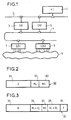
- a control / command installation is shown diagrammatically and comprises a control station 1 (PC) (level 2 of the CIM model) connected, through a network 2 for transmitting messages supporting a communication protocol by aperiodic example, to automation control computers 3 (CA1, CA2).
- the automation control computers 3 are connected, through a network 4 for transmitting messages supporting a communication protocol, for example periodic, to remote interfaces 5 (E / S1, E / S2) which receive data or transmit data to a physical process 6 to be checked.
- the data processing process connecting the remote interfaces to the automation control computers is real time.
- the characteristics of networks 2 and 4 are such that the transmission times of messages between the remote interfaces 5 and the processors 3 are much lower than the transmission times of messages between the driving station 1 and the computers 3.
- Document EP-A-0445954 also discloses a system for synchronizing concurrent tasks which is based on the use of virtual time stamps (counters). With this known system, the stability dates of the messages are not taken into account.
- the object of the invention is to remedy the aforementioned drawbacks with a view to favoring the processing of certain messages over others while maintaining perfect synchronization of processing of messages between redundant tasks.
- the subject of the invention is a method of operating a data processing system adapted to execute in parallel two or more redundant tasks receiving identical data, in which messages including each of such data and a time stamp are transferred to the redundant tasks, the messages transferred to each redundant task being ordered in chronological order to be processed by the redundant task in this order and a stability date is determined for each message, this stability date defining the instant from which the redundant task can process the message, characterized in that the scheduling of the messages transferred to a redundant task is based on the time stamps of the messages increased respectively by first time constants and the stability dates of the messages are determined on the basis of the timestamps of these messages increased respectively by second time constants.
- each message there is included in each message a code identifying the source of the message which may be a sending task.
- the method according to the invention ensures that the waiting time for messages from priority tasks is reduced to the maximum. If there is only one priority sending task, the messages for this task have zero waiting time for their processing by the redundant tasks. In addition, the waiting times for messages for tasks that send messages and are not priority are equal to each other and reduced to the minimum.
- FIG. 1 represents a control / command installation.
- Figure 2 shows the structure of a message.
- Figure 3 shows a record in a message queue.
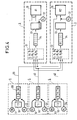
- FIG. 4 represents, in the form of functional blocks, the task synchronization system according to the invention for the control / command installation of FIG. 1.
- Figure 5 is a flowchart illustrating one way to implement stable message detection for the synchronization system.
- each remote interface 5 conventionally consists of a processor with memory and peripheral equipment. They each have a local clock 52,54.
- a task T1 transmitting data D bearing the reference 10 resides in the driving position 1.
- the driving position consists of a processor with memory and peripheral equipment. It also has a local clock 12.
- Each automation control computer 3 also consists of a processor with memory and peripheral. They each include a local clock 32.
- These output interface tasks are coupled to the transmitting tasks via data input / output queues (not shown) to ensure the passage of data over the 2.4 networks to the computers 3. In this way, the structure and the operation of the transmitting tasks are independent of the synchronization of the redundant tasks.
- each message 60 comprises a data zone 61 in which is written a data D supplied by a transmitting task, a zone 62 in which is written the date HL constituting a timestamp given by a local clock 12,52,54 at the time of the formation of the message and an area 63 in which a task or site identification code NS is registered.
- Each output interface task codes the messages it forms according to the appropriate communication protocol to send them on networks 20 and 40.
- the message identification code is a numerical value.
- the messages formed at the output of task T1 have an identification code equal to 1.
- the messages formed at the output of task T2 have an identification code equal to 2 and the messages formed at the output of task T3 have an identification code equal to 3.
- the messages 60 can be easily differentiated according to their respective origins.
- the redundant task synchronization system R1, R2 then comprises input interface tasks distributed in the computers 3.
- Each input interface task has the function of entering the messages 60 received by a computer 3, possibly delaying the messages received in a queue 33 and supply the data encapsulated in the messages to the redundant task 30 when the messages are stable.
- This input interface task uses time constants precalculated and recorded in memory or calculated online in the computer 3 to determine the date of stability of the messages and the order of taking into account of the data supplied to the redundant task 30.
- m1, m2, m3 are the minimum transfer times of data D between tasks T1, T2, T3 and task R1.
- M1, M2, M3 are the maximum transfer times of a data D between tasks T1, T2, T3 and task R1.
- a transfer time is equal to the difference between the local date of reception of data by a task 30 in a processor 3 and the local date of transmission of this data by a task 10.50 in a processor 1.5.
- R1, R2, R3 respectively for tasks T1, T2, T3 from the following relation, in which the indices i and j range from 1 to 3.
- R i max (M j - VS j ) + C i , i # i
- the time constants C1, C2, C3 and R1, R2, R3 are previously recorded in the computer 3 to be selectively retrieved from an identification code.
- the values m k and M k of the measured transfer times are recorded in the computer 3 in order to be recovered selectively from an identification code, the calculation of the time constants C and R being done online.
- Each record 34 comprises a field 35 in which is entered the data D of a message, a field 36 in which is inscribed the stamp HL of the message increased by the constant Cj whose index j corresponds to or is equal to the identification code NS of the message , a field 37 in which is inscribed the identification code NS of the message, a field 38 in which is inscribed the stamp value HL of the message increased by the time constant R j whose index j corresponds to or is equal to NS identification code of the message, and a field 39 in which a Boolean control variable F positioned at "False" is written.
- the value of field 38 of a record corresponds to the stability date of a message.
- Boolean constants B are recorded in the computer 3 in correspondence with the identification codes.
- the value of the Boolean constant is "True” if: max (M j - VS j ) - (m i - VS i )> 0 for j # i
- the expression max (M j - C j )) (m i - C i ) gives the maximum waiting time for a piece of data in a message waiting to be stable. Otherwise, this waiting time is zero.
- the messages 60 passing through the networks 2 and 4 are received in sequence at the input of the automation control computer 3 by the input interface task.
- a message 60 received is decoded at 100 to recover the data D, the stamp HL and the identification code NS of the message.
- the time constants Cj, Rj and the Boolean constant Bj whose index j corresponds to the identification code NS are retrieved at 110.
- the Boolean constant Bj is compared to the value "True" in 120. If it is not equal to "True”, the data D of the received message is supplied directly to the redundant task R1 in 130 since this message is stable. Otherwise, a record 34 is formed from the message 60 at 140 and is placed in the queue 33 so that the records 34 are ordered in ascending order of the field values 36. If two Consecutive records in queue 33 have the same field value 36, the one with the lowest field value 37 precedes the other in the queue.
- the records 34 in the queue 33 are scanned at 150.
- the control variable F in the field 39 is compared with the value "True” at 160. If this control variable is equal to "True”, processing continues at 150 for the next record 34 until all of the records have been scanned. Otherwise, the stability date in field 38 for the scanned record is compared in 170 with the current date supplied by the local clock 32 of the automation control computer 3. If this stability date is less than the current date, the control variable F of the field 39 is positioned to "True” in 180 and the processing continues in 150 and otherwise in 150. When all the records 34 have been scanned in the queue 33, the processing continues in 190.
- Steps 100 to 190 are repeated for each new message 63 received as input for this automation control computer.
- the input interface task described above works in the same way for the other redundant task residing in the other automation control computer, the time constants only having to be adapted to the data transfer times for this computer. .
- the invention can therefore easily be applied to a number of automation control computers and redundant tasks greater than 2.
Abstract
Description
L'invention porte sur un procédé de fonctionnement d'un système de traitement de données adapté pour exécuter en parallèle deux ou plusieurs tâches redondantes réceptrices de données identiques, dans lequel des messages, incluant chacun de telles données et une estampille temporelle, sont transférés aux tâches redondantes, les messages transférés à chaque tâche redondante étant ordonnés selon un ordre chronologique pour être traités par la tâche redondante selon cet ordre et une date de stabilité est déterminée pour chaque message, cette date de stabilité définissant l'instant à partir duquel la tâche redondante peut traiter le message.A method of operating a data processing system adapted to execute two or more redundant tasks receiving identical data in parallel, in which messages, each including such data and a time stamp, is transferred to redundant tasks, the messages transferred to each redundant task being ordered in chronological order to be processed by the redundant task in this order and a stability date is determined for each message, this stability date defining the moment from which the task redundant can process the message.
L'invention s'applique plus particulièrement à la synchronisation de tâches redondantes résidant dans des calculateurs de contrôle d'automatisme (niveau 1 du modèle CIM) d'une installation de contrôle/commande industriel.The invention applies more particularly to the synchronization of redundant tasks residing in automation control computers (
La redondance active sur les entrées de tâches redondantes (dupliquées dans des processeurs différents) est une technique connue pour mettre en oeuvre des procédures de tolérance aux fautes. Les tâches redondantes prennent en entrée les mêmes données et exécutent le même programme de manière qu'une commutation de la sortie des tâches redondantes est possible en cas de défaillance de l'une de celles-ci. On ne considère ici que des tâches redondantes ne réagissant qu'aux données d'entrée (qui sont généralement fournies par des tâches émettrices de telles données qui résident dans d'autres processeurs). Pour avoir une redondance active, il est nécessaire que les tâches redondantes aient le même comportement. Ceci est obtenu en s'arrangeant de manière que les tâches redondantes prennent leurs données d'entrée dans le même ordre chronologique, c'est-à-dire soient synchronisées.Active redundancy on redundant task inputs (duplicated in different processors) is a known technique for implementing fault tolerance procedures. Redundant tasks take the same data as input and execute the same program so that switching of the output of redundant tasks is possible if one of them fails. We consider here only redundant tasks reacting only to the input data (which are generally provided by tasks transmitting such data which reside in other processors). To have active redundancy, it is necessary that the redundant tasks have the same behavior. This is achieved by arranging so that the redundant tasks take their input data in the same chronological order, i.e. are synchronized.
On connaît du document "ACM Computing Surveys -Vol. 22 - N°4 - Dec 1990: Implementing Fault-Tolerant Services Using State Machine Approach: A tutorial de F. Schneider", un système de synchronisation de tâches redondantes dans lequel l'estampille temporelle incluse dans chaque message est constituée par une date d'envoi du message. Cette date d'envoi est donnée classiquement par une horloge du processeur dans lequel réside la tâche émettrice du message. Les granularités des horloges des processeurs (des tâches émettrices de messages) sont suffisamment petites pour qu'en aucun cas, deux messages produits en sortie du même processeur aient la même estampille temporelle. Les processeurs dans lesquels résident les tâches redondantes ont eux aussi une horloge locale et les horloges de tous les processeurs sont éventuellement resynchronisées, comme cela est bien connu, en vue de maintenir une référence de temps identique d'un processeur à l'autre. Le document "Fault-Tolerant Clock Synchronization in Distributed Systems-COMPUTER-IEEE-Octobre 1990" décrit des procédures de synchronisation d'horloges de processeurs.We know from the document "ACM Computing Surveys -Vol. 22 - N ° 4 - Dec 1990: Implementing Fault-Tolerant Services Using State Machine Approach: A tutorial by F. Schneider ", a redundant task synchronization system in which the timestamp included in each message is constituted by a message sending date. This sending date is conventionally given by a clock of the processor in which the task sending the message resides. The granularities of the clocks of the processors (of the tasks sending messages) are small enough so that in no case, two messages produced at the output of the same processor have the same time stamp. processors in which the redundant tasks reside also have a local clock and the clocks of all the processors are possibly resynchronized, as is well known, in order to maintain an identical time reference from one processor to another. "Fault-Tolerant Clock Synchronization in Distributed Systems-COMPUTER-IEEE-October 1990" describes synchronization procedures n of processor clocks.
Le fonctionnement du système de synchronisation de tâches redondantes connu du document "ACM Computing Surveys..." est le suivant.The operation of the redundant task synchronization system known from the document "ACM Computing Surveys ..." is as follows.
Une constante de temps unique est déterminée au préalable, à partir de temps de transfert de données mesurés entre chaque tâche émettrice et chaque tâche redondante. La constante de temps est égale au maxima de ces temps de transfert mesurés.A single time constant is determined beforehand, from the data transfer times measured between each sending task and each redundant task. The time constant is equal to the maximum of these measured transfer times.
Les messages reçus par un second processeur sont placés dans une file d'attente où ils sont ordonnés selon l'ordre croissant de leur estampille temporelle. Une date de stabilité, pour chaque message est calculée, cette date étant égale au cumul de l'estampille temporelle et de la constante de temps. Un message en entrée d'un processeur est dit stable lorsqu'aucun autre message ayant une estampille inférieure à celle de ce message ne peut plus arriver en entrée du processeur. Par conséquent un message stable est détecté lorsque l'horloge du second processeur donne une date supérieure à la date de stabilité du message. Celui-ci est alors prélevé de la file d'attente et la donnée qu'il contient est fournie à la tâche redondante résidant dans ce second processeur.Messages received by a second processor are placed in a queue where they are ordered in ascending order of their time stamp. A stability date, for each message is calculated, this date being equal to the total of the time stamp and the time constant. A message at the input of a processor is said to be stable when no other message having a stamp lower than that of this message can no longer arrive at the input of the processor. Consequently a stable message is detected when the clock of the second processor gives a date greater than the stability date of the message. This is then taken from the queue and the data it contains is supplied to the redundant task residing in this second processor.
Ce processus est effectué de la même façon sur l'autre second processeur.This process is performed in the same way on the other second processor.
De cette manière, les tâches redondantes prennent en compte les données qu'elles reçoivent selon une chronologie identique donnée par les estampilles temporelles des messages encapsulant ces données.In this way, the redundant tasks take into account the data they receive according to an identical chronology given by the time stamps of the messages encapsulating this data.
Ce système de synchronisation connu présente l'inconvénient suivant.This known synchronization system has the following drawback.
Sur la figure 1, une installation de contrôle/commande est représentée schématiquement et comprend un poste 1 de conduite (PC) (niveau 2 du modèle CIM) relié, au travers d'un réseau 2 de transmission de messages supportant un protocole de communication par exemple apériodique, à des calculateurs de contrôle d'automatisme 3 (CA1,CA2). Les calculateurs de contrôle d'automatisme 3 sont reliés, au travers d'un réseau 4 de transmission de messages supportant un protocole de communication par exemple périodique, à des interfaces 5 déportées (E/S1,E/S2) qui reçoivent des données ou transmettent des données à un procédé physique 6 à contrôler. Généralement, le processus de traitement de données reliant les interfaces déportées aux calculateurs de contrôle d'automatisme est temps réel. Les caractéristiques des réseaux 2 et 4 sont telles que les temps de transmission des messages entre les interfaces déportées 5 et les processeurs 3 sont très inférieurs aux temps de transmission des messages entre le poste 1 de conduite et les calculateurs 3.In FIG. 1, a control / command installation is shown diagrammatically and comprises a control station 1 (PC) (level 2 of the CIM model) connected, through a network 2 for transmitting messages supporting a communication protocol by aperiodic example, to automation control computers 3 (CA1, CA2). The
Du fait que la constante de temps utilisée pour la détermination de la date de stabilité de chaque message est uniforme pour tous les messages, ceux ci sont retardés en moyenne d'une même valeur de temps. Il en résulte qu'un premier message faisant partie d'un processus de traitement temps réel et ayant un temps de transfert petit (message provenant de l'interface déportée) par rapport à celui d'un second message (message provenant du poste de conduite) peut être retardé d'un temps beaucoup plus important que le second message si le second message bien que reçu après le premier message par le calculateur de contrôle d'automatisme, a une estampille plus petite que celle du premier message. Par conséquent, ce système connu de synchronisation de tâches redondantes est susceptible d'entraîner des dépassements de temps de réponse pour le processus temps réel et n'est donc pas adapté à une telle installation de contrôle/commande.Because the time constant used for determining the stability date of each message is uniform for all the messages, these are delayed on average by the same time value. As a result, a first message as part of a processing process real time and having a small transfer time (message from the remote interface) compared to that of a second message (message from the driver's seat) can be delayed by a much longer time than the second message if the second message, although received after the first message by the automation control computer, has a smaller stamp than that of the first message. Consequently, this known system for synchronizing redundant tasks is liable to cause overruns of response times for the real time process and is therefore not suitable for such a control / command installation.
On connaît aussi du document EP-A-0445954 un système de synchronisation de tâches concurrentes qui est basé sur l'utilisation d'estampilles de temps virtuel (compteurs). Avec ce système connu, on ne tient pas compte des dates de stabilité des messages.Document EP-A-0445954 also discloses a system for synchronizing concurrent tasks which is based on the use of virtual time stamps (counters). With this known system, the stability dates of the messages are not taken into account.
Le but de l'invention est de remédier aux inconvénients précités en vue de privilégier le traitement de certains messages par rapport à d'autres tout en maintenant une parfaite synchronisation de traitement des messages entre les tâches redondantes.The object of the invention is to remedy the aforementioned drawbacks with a view to favoring the processing of certain messages over others while maintaining perfect synchronization of processing of messages between redundant tasks.
A cet effet, l'invention a pour objet un procédé de fonctionnement d'un système de traitement de données adapté pour exécuter en parallèle deux ou plusieurs tâches redondantes réceptrices de données identiques, dans lequel des messages incluant chacun de telles données et une estampille temporelle sont transférés aux tâches redondantes, les messages transférés à chaque tâche redondante étant ordonnés selon un ordre chronologique pour être traités par la tâche redondante selon cet ordre et une date de stabilité est déterminée pour chaque message, cette date de stabilité définissant l'instant à partir duquel la tâche redondante peut traiter le message, caratérisé en ce que l'ordonnancement des messages transférés à une tâche redondante est basé sur les estampilles temporelles des messages augmentées respectivement de premières constantes de temps et les dates de stabilité des messages sont déterminées sur la base des estampilles de ces messages augmentées respectivement de secondes constantes de temps.To this end, the subject of the invention is a method of operating a data processing system adapted to execute in parallel two or more redundant tasks receiving identical data, in which messages including each of such data and a time stamp are transferred to the redundant tasks, the messages transferred to each redundant task being ordered in chronological order to be processed by the redundant task in this order and a stability date is determined for each message, this stability date defining the instant from which the redundant task can process the message, characterized in that the scheduling of the messages transferred to a redundant task is based on the time stamps of the messages increased respectively by first time constants and the stability dates of the messages are determined on the basis of the timestamps of these messages increased respectively by second time constants.
De cette façon, il est possible de minimiser les durées d'attente des messages provenant des tâches prioritaires. Ceci se traduit par un ordre de traitement des messages en attente pour une tâche redondante qui est différent de l'ordre chronologique définit par les estampilles des messages. Ceci se traduit aussi, par des dates de stabilité des messages qui sont ajustées en fonction de l'ordre de traitement de ces messages.In this way, it is possible to minimize the waiting times for messages from priority tasks. This results in an order for processing the messages waiting for a redundant task which is different from the chronological order defined by the timestamps of the messages. This also results in message stability dates which are adjusted according to the processing order of these messages.
Selon un mode de réalisation particulièrement simple, on inclut dans chaque message un code identifiant la source du message qui peut être une tâche émettrice.According to a particularly simple embodiment, there is included in each message a code identifying the source of the message which may be a sending task.
Le procédé selon l'invention assure que la durée d'attente des messages provenant des tâches prioritaires est réduite au maximum. Si il n'y a qu'une seule tâche émettrice prioritaire, les messages pour cette tâche ont un temps d'attente nul pour leur traitement par les tâches redondantes. Par ailleurs les temps d'attente des messages pour des tâches émettrices de messages et non prioritaires sont égaux entre eux et réduits au maximum.The method according to the invention ensures that the waiting time for messages from priority tasks is reduced to the maximum. If there is only one priority sending task, the messages for this task have zero waiting time for their processing by the redundant tasks. In addition, the waiting times for messages for tasks that send messages and are not priority are equal to each other and reduced to the minimum.
Un exemple de réalisation de l'invention est décrit ci-dessous en détail en référence aux dessins.An exemplary embodiment of the invention is described below in detail with reference to the drawings.
La figure 1 représente une installation de contrôle/commande.FIG. 1 represents a control / command installation.
La figure 2 représente la structure d'un message.Figure 2 shows the structure of a message.
La figure 3 représente un enregistrement dans une file d'attente de messages.Figure 3 shows a record in a message queue.
La figure 4 représente sous forme de blocs fonctionnels, le système de synchronisation de tâches selon l'invention pour l'installation de contrôle/commande de la figure 1.FIG. 4 represents, in the form of functional blocks, the task synchronization system according to the invention for the control / command installation of FIG. 1.
La figure 5 est un organigramme illustrant une manière d'implémenter la détection de messages stables pour le système de synchronisation.Figure 5 is a flowchart illustrating one way to implement stable message detection for the synchronization system.
Sur la figure 4, deux tâches T1,T2 émettrices de données D portant la référence 50 résident dans des interfaces déportées 5. Chaque interface déportée 5 est constitué classiquement d'un processeur avec mémoire et équipement périphérique. Elles comportent chacune une horloge locale 52,54.In FIG. 4, two tasks T1, T2 transmitting data D bearing the
Une tâche T1 émettrice de données D portant la référence 10 réside dans le poste de conduite 1. Le poste de conduite est constitué d'un processeur avec mémoire et équipement périphérique. Il comporte aussi une horloge locale 12.A task T1 transmitting data D bearing the
Deux tâches redondantes R1,R2 réceptrices des données D fournies par les tâches T1,T2,T3 portent la référence 30 et résident dans les calculateurs de contrôle d'automatisme 3. Chaque calculateur de contrôle d'automatisme 3 est constitué aussi d'un processeur avec mémoire et périphérique. Ils comportent chacun une horloge locale 32.Two redundant tasks R1, R2 receiving data D provided by tasks T1, T2, T3 bear the
Le système de synchronisation des tâches R1 et R2 est maintenant décrit.The system for synchronizing tasks R1 and R2 is now described.
Il comporte d'abord des tâches interfaces de sortie (non représentées), réparties dans le poste de conduite 1 et les interfaces déportées 5, qui forment des messages 60 en sorties des tâches émettrices de données 10,50.It firstly comprises output interface tasks (not shown), distributed in the
Ces tâches interfaces de sortie se couplent aux tâches émettrices par l'intermédiaire de files d'entrée/sortie (non représentées) de données pour assurer le passage des données sur les réseaux 2,4 vers les calculateurs 3. De cette façon, la structure et le fonctionnement des tâches émettrices sont indépendants de la synchronisation des tâches redondantes.These output interface tasks are coupled to the transmitting tasks via data input / output queues (not shown) to ensure the passage of data over the 2.4 networks to the
Comme représenté sur la figure 2, chaque message 60 comprend une zone 61 de donnée dans laquelle est inscrite une donnée D fournie par une tâche émettrice, une zone 62 dans laquelle est inscrite la date HL constituant une estampille temporelle donnée par une horloge locale 12,52,54 au moment de la formation du message et une zone 63 dans laquelle est inscrit un code d'identification de tâche ou de site NS. Chaque tâche interface de sortie code les messages qu'elle forme selon le protocole de communication adéquat pour les envoyer sur les réseaux 20 et 40.As shown in FIG. 2, each
Selon un exemple de réalisation simple, le code d'identification des messages est une valeur numérique. Par exemple, les messages formés en sortie de la tâche T1 ont un code d'identification égal à 1. Les messages formés en sortie de la tâche T2 ont un code d'identification égal à 2 et les messages formés en sortie de la tâche T3 ont un code d'identification égal à 3. De cette manière, les messages 60 peuvent être différenciés facilement en fonction de leurs origines respectives.According to a simple embodiment, the message identification code is a numerical value. For example, the messages formed at the output of task T1 have an identification code equal to 1. The messages formed at the output of task T2 have an identification code equal to 2 and the messages formed at the output of task T3 have an identification code equal to 3. In this way, the
Le système de synchronisation des tâches redondantes R1,R2 comprend ensuite des tâches interfaces d'entrée réparties dans les calculateurs 3. Chaque tâche interface d'entrée a pour fonction de saisir les messages 60 reçus par un calculateur 3, retarder éventuellement les messages reçus dans une file d'attente 33 et fournir les données encapsulés dans les messages à la tâche redondante 30 quand les messages sont stables.The redundant task synchronization system R1, R2 then comprises input interface tasks distributed in the
Par la suite, le mode de fonctionnement du système de synchronisation sera décrit en faisant référence uniquement à une tâche interface d'entrée pour une tâche redondante 30 résidant dans un calculateur 3.Thereafter, the mode of operation of the synchronization system will be described with reference only to an input interface task for a
Cette tâche interface d'entrée exploite des constantes de temps précalculées et enregistrées en mémoire ou calculées en ligne dans le calculateur 3 pour déterminer la date de stabilité des messages et l'ordre de prise en compte des données fournies à la tâche redondante 30.This input interface task uses time constants precalculated and recorded in memory or calculated online in the
Pour déterminer ces constantes de temps, il est nécessaire de mesurer d'abord les temps de transfert minima et maxima d'une donnée D entre chaque tâche émettrice 10,50 et la tâche redondante 30. Dans le cas présent, m₁,m₂,m₃ sont les temps de transfert minima d'une donnée D entre les tâches T1,T2,T3 et la tâche R1. M₁,M₂,M₃ sont les temps de transfert maxima d'une données D entre les tâches T1,T2,T3 et la tâche R1. Un temps de transfert est égal à la différence entre la date locale de réception d'une données par une tâche 30 dans un processeur 3 et la date locale d'émission de cette donnée par une tâche 10,50 dans un processeur 1,5.To determine these time constants, it is necessary first to measure the minimum and maximum transfer times of a data item D between each emitting task 10.50 and the
Dans l'exemple de réalisation de l'invention, il est souhaitable de privilégier les messages provenant des interfaces déportées 5 par rapport à ceux provenant du poste de conduite 1. Les tâches T1,T2 sont donc des tâches prioritaires.In the exemplary embodiment of the invention, it is desirable to give priority to the messages coming from the
On détermine ensuite des premières constantes de temps C₁,C₂,C₃ respectivement pour les tâches T1,T2,T3 à partir des relations suivantes, où M est égal à 2 et N est égal à 3.![]()
![]()
![]()
et![]()
![]()
![]()
où
moyk= (mk+Mk)/2 pour k->1,N
diffk= (Mk-mk)/2 pour k->1,N.First time constants C₁, C₂, C₃ are then determined respectively for the tasks T1, T2, T3 from the following relationships, where M is equal to 2 and N is equal to 3. ![]()
![]()
![]()
and ![]()
![]()
![]()
or
avg k = (m k + M k ) / 2 for k-> 1, N
diff k = (M k -m k ) / 2 for k-> 1, N.
On détermine ensuite des secondes constantes de temps R₁,R₂,R₃ respectivement pour les tâches T₁,T₂,T₃ à partir de la relation suivante, dans laquelle les indices i et j vont de 1 à 3.![]()
![]()
De préférence, les constantes de temps C1,C2,C3 et R1,R2,R3 sont préalablement enregistrées dans le calculateur 3 pour être récupérées sélectivement à partir d'un code d'identification. En variante, les valeurs mk et Mk des temps de transfert mesurés sont enregistrées dans le calculateur 3 pour être récupérées sélectivement à partir d'un code d'identification, le calcul des constantes de temps C et R se faisant en ligne.Preferably, the time constants C1, C2, C3 and R1, R2, R3 are previously recorded in the
En réponse aux messages 60 reçus en entrée du calculateur 3, la tâche interface d'entrée décode ces messages et forme des enregistrements 34 qui sont maintenus en attente dans une file d'attente 33. Chaque enregistrement 34, comme visible en figure 3, comporte un champ 35 dans lequel est inscrit la donnée D d'un message, un champ 36 dans lequel est inscrite l'estampille HL du message augmentée de la constante Cj dont l'indice j correspond ou est égal au code d'identification NS du message, un champ 37 dans lequel est inscrit le code d'identification NS du message, un champ 38 dans lequel est inscrite la valeur d'estampille HL du message augmentée de la constante de temps Rj dont l'indice j correspond ou est égal au code d'identification NS du message, et un champ 39 dans lequel est inscrite une variable booléenne de contrôle F positionnée à "Faux".In response to the
La valeur du champ 38 d'un enregistrement correspond à la date de stabilité d'un message.The value of
Par ailleurs des constantes booléennes B sont enregistrées dans le calculateur 3 en correspondance avec les codes d'identification. Pour un code d'identification i, la valeur de la constante booléenne est "Vrai" si:![]()
![]()
Dans ce cas, l'expression max(Mj - Cj) ) (mi - Ci) donne le temps d'attente maximal d'une donnée d'un message en attente d'être stable. Dans le cas contraire, ce temps d'attente est nul.In this case, the expression max (M j - C j )) (m i - C i ) gives the maximum waiting time for a piece of data in a message waiting to be stable. Otherwise, this waiting time is zero.
Ces constantes booléennes seront exploitéss pour éviter de maintenir en attente les messages qui sont stables en entrée du processeur 3.These Boolean constants will be exploited to avoid keeping pending messages that are stable at the input of
Le fonctionnement de la tâche interface d'entrée est maintenant décrit en référence à la figure 5.The operation of the input interface task is now described with reference to Figure 5.
Les messages 60 transitant par les réseaux 2 et 4 sont reçus en séquence en entrée du calculateur de contrôle d'automatisme 3 par la tâche interface d'entrée.The
Un message 60 reçu est décodé en 100 pour récupérer la donnée D, l'estampille HL et le code d'identification NS du message.A
A partir du code d'identification NS, les constantes de temps Cj,Rj et la constante booléenne Bj dont l'indice j correspond au code d'identification NS sont récupérées en 110.From the identification code NS, the time constants Cj, Rj and the Boolean constant Bj whose index j corresponds to the identification code NS are retrieved at 110.
La constante booléenne Bj est comparée à la valeur "Vrai" en 120. Si elle n'est pas égale à "Vrai", la donnée D du message reçu est fournie directement à la tâche redondante R1 en 130 puisque ce message est stable. Dans le cas contraire, un enregistrement 34 est formé à partir du message 60 en 140 et est placé dans la file d'attente 33 de façon à ce que les enregistrements 34 soient ordonnés selon l'ordre croissant des valeurs de champ 36. Si deux enregistrements consécutifs dans la file d'attente 33 ont la même valeur de champ 36, celui ayant la plus faible valeur de champ 37 précède l'autre dans la file d'attente.The Boolean constant Bj is compared to the value "True" in 120. If it is not equal to "True", the data D of the received message is supplied directly to the redundant task R1 in 130 since this message is stable. Otherwise, a
Après les étapes 130 et 140, les enregistrements 34 dans la file d'attente 33 sont balayés en 150. Pour chaque enregistrement 34 balayé, la variable de contrôle F dans le champ 39 est comparée à la valeur "Vrai" en 160. Si cette variable de contrôle est égale à "Vrai", le traitement continue en 150 pour l'enregistrement 34 suivant jusqu'à ce que tous les enregistrements aient été balayés. Dans le cas contraire, la date de stabilité dans le champ 38 pour l'enregistrement balayé est comparée en 170 à la date actuelle fournie par l'horloge locale 32 du calculateur de contrôle d'automatisme 3. Si cette date de stabilité est inférieure à la date actuelle, la variable de contrôle F du champ 39 est positionnée à "Vrai" en 180 et le traitement continue en 150 et sinon en 150. Quand tous les enregistrements 34 ont été balayés dans la file d'attente 33, le traitement se poursuit en 190. Dans cette étape, si le premier enregistrement 34 de la file d'attente 33 (celui ayant un champ 36 de plus faible valeur) a une variable de contrôle F égale à "Vrai", une première donnée D dans le champ 35 de cet enregistrement est fournie à la tâche R1. L'enregistrement est simultanément enlevé de la file d'attente qui est réorganisée en conséquence. Si de nouveau la variable de contrôle F du premier enregistrement de la file d'attente est égale à "Vrai", une seconde donnée D dans le champ 35 de cet enregistrement est fournie à la tâche R1 qui la prendra en compte après la première donnée D. Cette procédure est répétée jusqu'à ce que la variable F soit égale à "Faux", auquel cas le traitement est terminé.After
Les étapes 100 à 190 sont répétées pour chaque nouveau message 63 reçu en entrée pour ce calculateur de contrôle d'automatisme. La tâche interface d'entrée ci-dessus décrite fonctionne de la même façon pour l'autre tâche redondante résidant dans l'autre calculateur de contrôle d'automatisme, les constantes de temps devant seulement être adaptées aux temps de transfert de données pour ce calculateur. L'invention peut par conséquent s'appliquer facilement à un nombre de calculateurs de contrôle d'automatisme et de tâches redondantes supérieur à 2.
Claims (4)

moyk= (mk+Mk)/2 pour k->1,N
diffk= (Mk-mk)/2 pour k->1,N
avg k = (m k + M k ) / 2 for k-> 1, N
diff k = (M k -m k) / 2 for k-> 1, N
Applications Claiming Priority (2)
| Application Number | Priority Date | Filing Date | Title |
|---|---|---|---|
| FR9300147A FR2700401B1 (en) | 1993-01-08 | 1993-01-08 | System for synchronizing responding tasks. |
| FR9300147 | 1993-01-08 |
Publications (2)
| Publication Number | Publication Date |
|---|---|
| EP0611171A1 true EP0611171A1 (en) | 1994-08-17 |
| EP0611171B1 EP0611171B1 (en) | 1998-03-25 |
Family
ID=9442913
Family Applications (1)
| Application Number | Title | Priority Date | Filing Date |
|---|---|---|---|
| EP94400025A Expired - Lifetime EP0611171B1 (en) | 1993-01-08 | 1994-01-05 | Synchronization system for redundant tasks |
Country Status (6)
| Country | Link |
|---|---|
| US (1) | US5551034A (en) |
| EP (1) | EP0611171B1 (en) |
| JP (1) | JPH06242980A (en) |
| DE (1) | DE69409142T2 (en) |
| ES (1) | ES2115888T3 (en) |
| FR (1) | FR2700401B1 (en) |
Cited By (3)
| Publication number | Priority date | Publication date | Assignee | Title |
|---|---|---|---|---|
| EP0754991A1 (en) * | 1995-07-20 | 1997-01-22 | Raytheon Company | Fault tolerant distributed control system |
| EP0777355A1 (en) * | 1995-12-01 | 1997-06-04 | Sextant Avionique | Secure data transmission and processing using the ARINC 629 protocol |
| EP1239369A1 (en) * | 2001-03-07 | 2002-09-11 | Siemens Aktiengesellschaft | Fault-tolerant computer system and method for its use |
Families Citing this family (17)
| Publication number | Priority date | Publication date | Assignee | Title |
|---|---|---|---|---|
| US6412017B1 (en) * | 1996-07-01 | 2002-06-25 | Microsoft Corporation | Urgent replication facility |
| US6049809A (en) * | 1996-10-30 | 2000-04-11 | Microsoft Corporation | Replication optimization system and method |
| WO2000036491A2 (en) * | 1998-12-17 | 2000-06-22 | California Institute Of Technology | Programming system and thread synchronization mechanisms for the development of selectively sequential and multithreaded computer programs |
| US6826752B1 (en) | 1998-12-17 | 2004-11-30 | California Institute Of Technology | Programming system and thread synchronization mechanisms for the development of selectively sequential and multithreaded computer programs |
| DE10002522C1 (en) * | 2000-01-21 | 2001-05-31 | Siemens Ag | Providing consistent input values in multi-processor unit for motor vehicle |
| EP1162540A1 (en) * | 2000-06-07 | 2001-12-12 | Siemens Schweiz AG | Method and apparatus for synchronizing a system with coupled data processing units |
| US6819960B1 (en) | 2001-08-13 | 2004-11-16 | Rockwell Software Inc. | Industrial controller automation interface |
| GB2387683B (en) * | 2002-04-19 | 2007-03-28 | Hewlett Packard Co | Workflow processing scheduler |
| WO2012003862A1 (en) * | 2010-07-06 | 2012-01-12 | Siemens Aktiengesellschaft | Device for synchronizing two processes of a redundant control system of an industrial automation arrangement |
| EP2701065B1 (en) * | 2012-08-24 | 2015-02-25 | Siemens Aktiengesellschaft | Method for operating a redundant automation system |
| WO2016067420A1 (en) * | 2014-10-30 | 2016-05-06 | 三菱電機株式会社 | Computer, and data processing method and program |
| US10230670B1 (en) * | 2014-11-10 | 2019-03-12 | Google Llc | Watermark-based message queue |
| JP6614373B1 (en) * | 2019-02-13 | 2019-12-04 | 富士通クライアントコンピューティング株式会社 | Inference processing system, inference processing apparatus, and program |
| US11349917B2 (en) | 2020-07-23 | 2022-05-31 | Pure Storage, Inc. | Replication handling among distinct networks |
| US11442652B1 (en) | 2020-07-23 | 2022-09-13 | Pure Storage, Inc. | Replication handling during storage system transportation |
| US11321351B2 (en) | 2020-09-08 | 2022-05-03 | International Business Machines Corporation | Adaptable legacy stateful workload |
| FR3130410B1 (en) * | 2021-12-14 | 2023-12-15 | Atos Worldgrid | System for controlling and assisting in the management of a critical industrial process and associated process |
Citations (2)
| Publication number | Priority date | Publication date | Assignee | Title |
|---|---|---|---|---|
| EP0445954A2 (en) * | 1990-03-05 | 1991-09-11 | International Business Machines Corporation | Synchronising concurrent processes in a computer system |
| US5168443A (en) * | 1990-09-26 | 1992-12-01 | Honeywell Inc. | Method for providing redundancy of a high speed pulse input I/O processor |
Family Cites Families (2)
| Publication number | Priority date | Publication date | Assignee | Title |
|---|---|---|---|---|
| US4577272A (en) * | 1983-06-27 | 1986-03-18 | E-Systems, Inc. | Fault tolerant and load sharing processing system |
| US4816989A (en) * | 1987-04-15 | 1989-03-28 | Allied-Signal Inc. | Synchronizer for a fault tolerant multiple node processing system |
-
1993
- 1993-01-08 FR FR9300147A patent/FR2700401B1/en not_active Expired - Fee Related
-
1994
- 1994-01-05 ES ES94400025T patent/ES2115888T3/en not_active Expired - Lifetime
- 1994-01-05 DE DE69409142T patent/DE69409142T2/en not_active Expired - Fee Related
- 1994-01-05 EP EP94400025A patent/EP0611171B1/en not_active Expired - Lifetime
- 1994-01-07 US US08/178,886 patent/US5551034A/en not_active Expired - Lifetime
- 1994-01-07 JP JP6000592A patent/JPH06242980A/en active Pending
Patent Citations (2)
| Publication number | Priority date | Publication date | Assignee | Title |
|---|---|---|---|---|
| EP0445954A2 (en) * | 1990-03-05 | 1991-09-11 | International Business Machines Corporation | Synchronising concurrent processes in a computer system |
| US5168443A (en) * | 1990-09-26 | 1992-12-01 | Honeywell Inc. | Method for providing redundancy of a high speed pulse input I/O processor |
Non-Patent Citations (1)
| Title |
|---|
| K. G. SHIN ET AL.: "Fault-tolerant clock synchronization in distributed systems", COMPUTER, vol. 23, no. 10, October 1990 (1990-10-01), LOS ALAMITOS, pages 33 - 42 * |
Cited By (9)
| Publication number | Priority date | Publication date | Assignee | Title |
|---|---|---|---|---|
| EP0754991A1 (en) * | 1995-07-20 | 1997-01-22 | Raytheon Company | Fault tolerant distributed control system |
| EP0777355A1 (en) * | 1995-12-01 | 1997-06-04 | Sextant Avionique | Secure data transmission and processing using the ARINC 629 protocol |
| FR2742015A1 (en) * | 1995-12-01 | 1997-06-06 | Sextant Avionique | METHOD FOR SECURING AN ACTION AND DEVICE FOR IMPLEMENTING IT |
| US5872827A (en) * | 1995-12-01 | 1999-02-16 | Sextant Avionique | Method for producing a result and device for the implementation thereof |
| EP1239369A1 (en) * | 2001-03-07 | 2002-09-11 | Siemens Aktiengesellschaft | Fault-tolerant computer system and method for its use |
| WO2002071223A1 (en) * | 2001-03-07 | 2002-09-12 | Siemens Aktiengesellschaft | Fault-tolerant computer cluster and a method for operating a cluster of this type |
| AU2002246102B2 (en) * | 2001-03-07 | 2005-04-14 | Siemens Aktiengesellschaft | Fault-tolerant computer cluster and a method for operating a cluster of this type |
| AU2002246102B9 (en) * | 2001-03-07 | 2005-04-21 | Siemens Aktiengesellschaft | Fault-tolerant computer cluster and a method for operating a cluster of this type |
| US7260740B2 (en) | 2001-03-07 | 2007-08-21 | Siemens Aktiengesellshcaft | Fault-tolerant computer cluster and a method for operating a cluster of this type |
Also Published As
| Publication number | Publication date |
|---|---|
| EP0611171B1 (en) | 1998-03-25 |
| FR2700401A1 (en) | 1994-07-13 |
| DE69409142T2 (en) | 1998-07-30 |
| DE69409142D1 (en) | 1998-04-30 |
| FR2700401B1 (en) | 1995-02-24 |
| JPH06242980A (en) | 1994-09-02 |
| ES2115888T3 (en) | 1998-07-01 |
| US5551034A (en) | 1996-08-27 |
Similar Documents
| Publication | Publication Date | Title |
|---|---|---|
| EP0611171A1 (en) | Synchronization system for redundant tasks | |
| EP1150138B1 (en) | Method and system for synchronisation of elements of a seismic system using a standard transmission network and an external time reference | |
| EP0893761A1 (en) | Device and method for dynamic regulation of the resource allocation in a computer system | |
| EP2476056B1 (en) | Method for the real-time ordering a set of non-cyclical multi-frame tasks | |
| US6990605B2 (en) | Methods and apparatus for recovering work of one computer by another computers | |
| EP3771182B1 (en) | Method for detecting and identifying devices communicating according to a modbus protocol and communication controller for implementing such a method | |
| EP2160682A2 (en) | Electronic card able to execute a command originating from a simulation system and a command originating from a diagnostic module and associated simulation method | |
| FR2526250A1 (en) | METHOD FOR AUTOMATICALLY TIMING STATIONS IN A MULTIPLEX TRANSMISSION AND DATA PROCESSING SYSTEM | |
| EP2592558A1 (en) | System and method for designing digital circuitry with an activity sensor | |
| EP0423663B1 (en) | Synchronised watch | |
| FR2769105A1 (en) | DEVICE AND METHOD FOR TAKING INTO ACCOUNT THE EXECUTION OF A TASK ON A COMPUTER SYSTEM | |
| WO2002056176A1 (en) | Fault-tolerant synchronisation device for a real-time computer network | |
| EP3881515B1 (en) | System for the formal supervision of communications | |
| EP2278466A1 (en) | Apparatus and method for the distributed execution of digital data processing | |
| EP3343375B1 (en) | A method and a system for monitoring batch processing of applications executed in it infrastructure | |
| FR3111227A1 (en) | Vehicle, method, software and device for collecting object information relating to one or more objects in a vehicle environment | |
| EP3874691A1 (en) | Method for measuring a transmission delay with control of degrees of contention applied to a data frame | |
| EP0555138A1 (en) | Method, system and processor for communications between a plurality of equipment subsystems | |
| FR3109040A1 (en) | Method of counting events from an external network | |
| EP1134657A1 (en) | Computing system and computation process implemented with said system | |
| FR3032289A1 (en) | METHOD FOR CONTROLLING DEPLOYMENT OF A PROGRAM TO BE EXECUTED IN A PARK OF MACHINES | |
| EP4074091A1 (en) | Synchronised adaptation of a virtual subset of a network dedicated to a service | |
| EP3893470B1 (en) | Method for optimising update of connected objects and application module | |
| EP3475847A1 (en) | Statistics server for optimising client-server queries | |
| EP3817294B1 (en) | Method and module for a connectivity regulation of connected objects. |
Legal Events
| Date | Code | Title | Description |
|---|---|---|---|
| PUAI | Public reference made under article 153(3) epc to a published international application that has entered the european phase |
Free format text: ORIGINAL CODE: 0009012 |
|
| AK | Designated contracting states |
Kind code of ref document: A1 Designated state(s): BE CH DE ES FR GB IT LI SE |
|
| 17P | Request for examination filed |
Effective date: 19941209 |
|
| 17Q | First examination report despatched |
Effective date: 19960926 |
|
| GRAG | Despatch of communication of intention to grant |
Free format text: ORIGINAL CODE: EPIDOS AGRA |
|
| GRAG | Despatch of communication of intention to grant |
Free format text: ORIGINAL CODE: EPIDOS AGRA |
|
| GRAH | Despatch of communication of intention to grant a patent |
Free format text: ORIGINAL CODE: EPIDOS IGRA |
|
| GRAH | Despatch of communication of intention to grant a patent |
Free format text: ORIGINAL CODE: EPIDOS IGRA |
|
| RAP1 | Party data changed (applicant data changed or rights of an application transferred) |
Owner name: ALCATEL ALSTHOM COMPAGNIE GENERALE D'ELECTRICITE |
|
| GRAA | (expected) grant |
Free format text: ORIGINAL CODE: 0009210 |
|
| AK | Designated contracting states |
Kind code of ref document: B1 Designated state(s): BE CH DE ES FR GB IT LI SE |
|
| ITF | It: translation for a ep patent filed |
Owner name: JACOBACCI & PERANI S.P.A. |
|
| REG | Reference to a national code |
Ref country code: CH Ref legal event code: NV Representative=s name: GEC ALSTHOM SALES NETWORK SA Ref country code: CH Ref legal event code: EP |
|
| REF | Corresponds to: |
Ref document number: 69409142 Country of ref document: DE Date of ref document: 19980430 |
|
| GBT | Gb: translation of ep patent filed (gb section 77(6)(a)/1977) |
Effective date: 19980429 |
|
| REG | Reference to a national code |
Ref country code: ES Ref legal event code: FG2A Ref document number: 2115888 Country of ref document: ES Kind code of ref document: T3 |
|
| PLBE | No opposition filed within time limit |
Free format text: ORIGINAL CODE: 0009261 |
|
| STAA | Information on the status of an ep patent application or granted ep patent |
Free format text: STATUS: NO OPPOSITION FILED WITHIN TIME LIMIT |
|
| RAP4 | Party data changed (patent owner data changed or rights of a patent transferred) |
Owner name: ALCATEL |
|
| 26N | No opposition filed | ||
| PGFP | Annual fee paid to national office [announced via postgrant information from national office to epo] |
Ref country code: CH Payment date: 20011217 Year of fee payment: 9 |
|
| REG | Reference to a national code |
Ref country code: GB Ref legal event code: IF02 |
|
| PGFP | Annual fee paid to national office [announced via postgrant information from national office to epo] |
Ref country code: SE Payment date: 20020102 Year of fee payment: 9 |
|
| PGFP | Annual fee paid to national office [announced via postgrant information from national office to epo] |
Ref country code: BE Payment date: 20020220 Year of fee payment: 9 |
|
| PG25 | Lapsed in a contracting state [announced via postgrant information from national office to epo] |
Ref country code: SE Free format text: LAPSE BECAUSE OF NON-PAYMENT OF DUE FEES Effective date: 20030106 |
|
| PGFP | Annual fee paid to national office [announced via postgrant information from national office to epo] |
Ref country code: ES Payment date: 20030124 Year of fee payment: 10 |
|
| PG25 | Lapsed in a contracting state [announced via postgrant information from national office to epo] |
Ref country code: LI Free format text: LAPSE BECAUSE OF NON-PAYMENT OF DUE FEES Effective date: 20030131 Ref country code: CH Free format text: LAPSE BECAUSE OF NON-PAYMENT OF DUE FEES Effective date: 20030131 Ref country code: BE Free format text: LAPSE BECAUSE OF NON-PAYMENT OF DUE FEES Effective date: 20030131 |
|
| EUG | Se: european patent has lapsed | ||
| REG | Reference to a national code |
Ref country code: CH Ref legal event code: PL |
|
| PG25 | Lapsed in a contracting state [announced via postgrant information from national office to epo] |
Ref country code: ES Free format text: LAPSE BECAUSE OF NON-PAYMENT OF DUE FEES Effective date: 20040107 |
|
| PG25 | Lapsed in a contracting state [announced via postgrant information from national office to epo] |
Ref country code: IT Free format text: LAPSE BECAUSE OF NON-PAYMENT OF DUE FEES;WARNING: LAPSES OF ITALIAN PATENTS WITH EFFECTIVE DATE BEFORE 2007 MAY HAVE OCCURRED AT ANY TIME BEFORE 2007. THE CORRECT EFFECTIVE DATE MAY BE DIFFERENT FROM THE ONE RECORDED. Effective date: 20050105 |
|
| REG | Reference to a national code |
Ref country code: ES Ref legal event code: FD2A Effective date: 20040107 |
|
| PGFP | Annual fee paid to national office [announced via postgrant information from national office to epo] |
Ref country code: DE Payment date: 20090122 Year of fee payment: 16 |
|
| PGFP | Annual fee paid to national office [announced via postgrant information from national office to epo] |
Ref country code: GB Payment date: 20090122 Year of fee payment: 16 |
|
| PGFP | Annual fee paid to national office [announced via postgrant information from national office to epo] |
Ref country code: FR Payment date: 20090115 Year of fee payment: 16 |
|
| GBPC | Gb: european patent ceased through non-payment of renewal fee |
Effective date: 20100105 |
|
| REG | Reference to a national code |
Ref country code: FR Ref legal event code: ST Effective date: 20100930 |
|
| PG25 | Lapsed in a contracting state [announced via postgrant information from national office to epo] |
Ref country code: FR Free format text: LAPSE BECAUSE OF NON-PAYMENT OF DUE FEES Effective date: 20100201 |
|
| PG25 | Lapsed in a contracting state [announced via postgrant information from national office to epo] |
Ref country code: DE Free format text: LAPSE BECAUSE OF NON-PAYMENT OF DUE FEES Effective date: 20100803 |
|
| PG25 | Lapsed in a contracting state [announced via postgrant information from national office to epo] |
Ref country code: GB Free format text: LAPSE BECAUSE OF NON-PAYMENT OF DUE FEES Effective date: 20100105 |