EP0610855A2 - Electrical connector with terminal retaining means - Google Patents
Electrical connector with terminal retaining means Download PDFInfo
- Publication number
- EP0610855A2 EP0610855A2 EP94101820A EP94101820A EP0610855A2 EP 0610855 A2 EP0610855 A2 EP 0610855A2 EP 94101820 A EP94101820 A EP 94101820A EP 94101820 A EP94101820 A EP 94101820A EP 0610855 A2 EP0610855 A2 EP 0610855A2
- Authority
- EP
- European Patent Office
- Prior art keywords
- housing
- retainer
- guide
- strips
- protrusions
- Prior art date
- Legal status (The legal status is an assumption and is not a legal conclusion. Google has not performed a legal analysis and makes no representation as to the accuracy of the status listed.)
- Granted
Links
Images


Classifications
-
- H—ELECTRICITY
- H01—ELECTRIC ELEMENTS
- H01R—ELECTRICALLY-CONDUCTIVE CONNECTIONS; STRUCTURAL ASSOCIATIONS OF A PLURALITY OF MUTUALLY-INSULATED ELECTRICAL CONNECTING ELEMENTS; COUPLING DEVICES; CURRENT COLLECTORS
- H01R13/00—Details of coupling devices of the kinds covered by groups H01R12/70 or H01R24/00 - H01R33/00
- H01R13/40—Securing contact members in or to a base or case; Insulating of contact members
- H01R13/42—Securing in a demountable manner
- H01R13/436—Securing a plurality of contact members by one locking piece or operation
- H01R13/4367—Insertion of locking piece from the rear
- H01R13/4368—Insertion of locking piece from the rear comprising a temporary and a final locking position
Definitions
- This invention relates to an electrical connector having cavities receiving terminals each of which has one end connected to a lead, and more particularly to such a connector employing a retainer providing double engagement for the terminals received in the cavities so that the terminals can be held in position therein.
- FIGS. 7 and 8 illustrate a conventional electrical connector employing the retainer providing double engagement for the terminals.
- FIGS. 9 and 10 illustrate another conventional connector employing such a retainer.
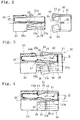
- the connector comprises a housing 1 with a cylindrical cavities 1a receiving respective terminals 2. Each cavity 1a has an open rear end through which the terminal 2 is inserted.
- a cap-shaped retainer 3 is fitted on an outer periphery of the rear end of the housing 1.
- the retainer 3 has terminal insertion apertures 3a corresponding to the respective rear openings of the cavities 1a.
- Each terminal insertion aperture 3a has a protrusion 3b formed on the upper edge of the inner periphery thereof so that it protrudes toward the interior of the corresponding cavity 1a.
- each protrusion 3b enters into the corresponding cavity 1a to collide with the rear end of the terminal 2.
- the state of the housing 1 and the retainer 3 as shown in FIG. 8 will be referred to as "full engagement.”
- the retainer 3 can be engaged with the housing 1 before the full engagement state, assuming a position away upwardly from its position in the full engagement state, as shown in FIG. 7. In this position away upwardly from that in the full engagement state, each protrusion 3a is out of the corresponding cavity 1a and away upwardly therefrom. Accordingly, the protrusions 3a do not interrupt the terminal 2 being inserted into the cavities 1a respectively.
- the state of the housing 1 and the retainer 3 as shown in FIG. 7 will be referred to as "preliminary engagement.”
- the terminals 2 are inserted into the cavities 1a from the terminal insertion apertures 3a respectively with the housing 1 and the retainer 3 in the state of preliminary engagement. Forced down in the direction of arrow A in the preliminary engagement state as shown in FIG. 8, the retainer 3 is thrust in the direction of arrow B in FIG. 8.
- two-stage operation is necessitated in order that the retainer 3 is engaged with the housing 1 in the full engagement state, that is, pushing the retainer 3 in the direction of arrow A and thrusting it in the direction of arrow B.
- the two-stage operation requires an operator to be well skilled in it, resulting in a problem in working efficiency. Furthermore, the two-stage operation prevents automatization of the terminal inserting work.
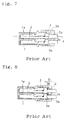
- the connector shown in FIGS. 9 and 10 comprises a housing 4 with cylindrical cavities 4a receiving terminals 5 respectively.
- a space or retainer receiving portion 4b is defined in a upper rear portion of each cavity 4a for receiving a retainer 6.
- the retainer 6 has in its distal end a flexible arm 6a and is inserted into the retainer receiving portion 4b from the side of the arm 6a.
- the retainer 6 has a rear end base 6a which is engageable at its top face with a ceiling face of the retainer receiving portion 4b.
- the retainer 6 is engaged with the ceiling face of the retainer receiving portion 4b both when it assumes a preliminary engagement position where the base 6a is not completely received in the retainer receiving portion 4b, as shown in FIG. 9 and when it assumes a full engagement position where it is completely received in the retainer receiving portion 4b.
- the retainer receiving portion 4b has an inclined face 4c in its front end.
- the distal end of the arm 6a is positioned at the side of the open end of the housing relative to the inclined face 4c when the retainer 6 is at the preliminary engagement position.
- the distal end of the arm 6a is flexed downwardly along the inclined face 4c so that the arm 6a advances downwardly into the cavity 4a.
- the retainer 6 is inserted into the retainer receiving portion 4b from its side of the arm portion 6a such that the retainer 6 is engaged with the housing at the preliminary engagement position. Then, the terminals 5 are inserted into the respective cavities 4a and the retainer 6 is thrust in the direction of arrow C in FIG. 10 such that it is moved from the preliminary engagement position to the full engagement position.
- the arm 6a of the retainer 6 then collides with the inclined face 4c to be flexed downwardly.
- the arm 6a then collides with a recess 5a of the terminal 5 to push the same deep into the cavity 4a, thereby holding the terminals 5 received in the respective cavities 4a.
- the arm 6a Since the arm 6a is flexed when the retainer 6 is inserted into the retainer receiving portion 4b, the number of the arms 6a to be flexed is increased as the number of the terminals received in the respective cavities 4a is increased. Accordingly, a large operating force is necessary and results in reduction in the working efficiency. Furthermore, the arm 6a has lost its returning force when the retainer 6 is returned to the preliminary engagement position in inspection of the connector. In this case, the arm 6a remains flexed downwardly and accordingly, the terminal 5 cannot be pulled out.
- an object of the present invention is to provide an electrical connector which can be assembled readily and wherein the retainer can be guided by guide means with a simple construction and no structures are not provided on the outer face of the housing.
- the present invention provides an electrical connector comprising a housing having a plurality of cavities receiving a plurality of terminals therein respectively and a retainer engaged with the housing when assuming a full engagement position and a preliminary engagement position, the retainer having engagement strips invading the respective cavities, the engagement strips engaging the terminals in the cavities respectively to thereby hold the same in position when the retainer assumes the full engagement position, the engagement strips allowing insertion and pullout of the terminals when the retainer assumes the preliminary engagement position, characterized in that the housing has an opening communicating to the terminal receiving cavities and the retainer includes a body engaged with the housing and moved in parallel with the same and lock strips coupled to the body and bendable relative thereto, each lock strip being engaged with the housing through guide means and moving toward and away from the housing with the parallel movement of the body, each lock strip having protrusions disposed to face the opening of the housing, the protrusions moving into and out of the opening of the housing when the lock strips moving toward and away from the housing, the lock strips engaging the terminals received in the cavities
- Each lock strip is moved toward or away from the housing by the guide means when the retainer is moved along the housing in the direction parallel to the same.
- the protrusions of the lock strips move into the cavities from the opening of the housing respectively.
- the protrusions are engaged with the respective terminals to hold them in position.
- the lock strips are moved away from the housing by the guide means.
- the protrusions of the lock strips are caused to move out of the opening of the housing. Consequently, the terminals are disengaged from the respective protrusions of the lock strips and taken out.
- the connector can be assembled readily. Furthermore, since the lock strips are moved away from the housing by the guide means with the movement of the retainer even after lapse of time, pullout of the terminals is not prevented by the lock strips.
- the guide means may comprise a plurality of guide concave portions formed in the housing and a plurality of guide protrusions formed on the retainer and engaging the guide grooves respectively, each guide concave portion being curved so that the lock strip is drawn to the housing side in the parallel movement of the retainer.
- each guide protrusion moves in the guide concave portion in engagement therewith when the retainer body is moved in parallel to the housing, so that each lock strip is moved toward and away from the housing along the curved concave portion.
- the guide concave portions may be formed in the retainer with the guide protrusions formed on the housing.
- the guide means can be achieved by a simple construction of the guide concave portions and the guide protrusions.
- the retainer may have two pairs of holding strips each pair holding the housing therebetween from the outside, the guide concave portions being formed in the holding strips, and the housing may have on opposite sides thereof sliding faces held by the holding strips, the guide protrusions being formed on the sliding faces.
- each lock strip of the retainer Since the holding strips are provided on the opposite side ends of each lock strip of the retainer for holding the housing, they are engaged with the housing at both sides of each lock strip. Each lock strip can stably be held at the housing side even when a load is applied to the protrusion of each lock strip.
- the housing may have a plurality of guide grooves extending in parallel to the direction of movement of the retainer, the guide concave portions being formed in the guide convex portions, and the retainer may have a plurality of guide convex portions inserted into the guide grooves of the housing respectively, the guide protrusions being formed on sliding faces of the guide groove.
- the guide concave portions of the retainer move into the respective guide grooves of the housing and further move in parallel to the housing.
- the lock strips of the retainer are moved toward and away from the housing by the guide concave portions and the guide protrusions engaged with the guide concave portions respectively.
- the guide concave portions and the guide protrusions may be provided either on the side of the guide grooves or the side of the guide convex portions. Since the guide convex portions are formed on the retainer side with the guide grooves formed in the housing side, the outer side face of the housing can be used for other purposes.
- the retainer may include a cylindrical portion into which the housing is inserted and the housing can be moved back and forth axially along the peripheral face of the cylindrical portion of the retainer. Since the retainer body is formed into the cylindrical shape, the retainer body can be moved back and forth axially along the housing in the direction parallel to the same. Consequently, the connector can be assembled readily only by insertion of the housing into the retainer.
- the retainer may have a plurality of sliding strips holding the housing therebetween from the outside thereof and the housing may have on the opposite sides slide faces, the sliding strips being moved back and forth sliding on the slide faces. Each sliding strip moves back and forth in the direction parallel 1 to the housing, sliding on the slide face.
- the retainer body has the guide means for engagement with the housing without the cylindrical portion, which improves the freedom of the configuration of the retainer or the connector.
- FIGS. 1 to 4 A first embodiment of the present invention will be described with reference to FIGS. 1 to 4.
- the invention is applied to a female connector.
- an electrical connector 10 comprises a housing 20 generally formed into a rectangular parallelepiped and a retainer 30 attached to the rear end side of the housing 20.
- a plurality of terminals 40 each having an end connected to a lead by way of crimping are enclosed in the housing.
- the interior of the housing 20 is partitioned by partition walls 21 into two rows of terminal receiving cavities 22, each row having four cavities.
- the front portion 23 of the housing 20 closes the whole periphery of the terminal receiving cavities 22 while the top of the upper row of the cavities 22 and the bottom of the lower row of the cavities 20 are open in the rear portion 24 of the housing 20 such that an opening 22a is provided, as shown in FIG. 2.
- a front wall of the front portion 23 have small apertures 25 through which male terminals (not shown) are inserted.
- Lock arms 26 are formed on the front end of the bottom of the rear portion 24. Each lock arm 26 can be flexed vertically.
- Each lock arm 26 has an engagement protrusion 26a formed on the upper face thereof. Each engagement protrusion 26a has such a configuration that it can be inserted into an engagement aperture 41 formed in the underside of each terminal 40 which will be described later, and held therein.
- Each side wall of the rear portion further has two groove-like guide concave portions 28 extending from the rear end thereof toward the front end over and above the engagement holes 27a.
- Each guide concave portion 28 extends generally horizontally from the rear end of the rear portion 24 and is curved at its front end 28a toward the central portion.
- the retainer 30 includes a body 31 formed into a rectangular cylindrical shape and can enclose the rear portion 24 of the housing 20 therein.
- Two plate-shaped lock strips 32 are formed on the front portion of the body 31.
- the lock strips 32 are connected to upper and lower walls of the body 31 respectively.
- Each lock strip 32 has a connection portion whose thickness is reduced such that it is bendable.
- Four protrusions 33 are formed on the inside face of each lock strip 32 so as to correspond to each rows of the cavities 22.
- Two holding strips 34 are formed on the right-hand and left-hand ends of each lock strip 32. Each holding strip 34 spreads toward the central side in the vertical direction. A space is defined between each holding strip 34 and its corresponding one so that the rear portion 24 of the housing 20 can be held therebetween.
- Guide protrusions 35 are formed on the inner sides of the holding strips 34 respectively.
- the guide protrusions 35 are engageable with the respective guide concave portions 28 formed in the rear portion 24 of the housing 20.
- the guide protrusions 35 are so positioned that the lock strips 32 extends upwardly and downwardly respectively when inserted into the horizontal portions of the respective guide concave portions 28.
- the guide protrusions 35 are further positioned so that each lock strip 32 is drawn to be planer with the body 31 when advancing forward along the respective grooves 28 to reach the front end curved portions.
- Both side walls of the body 31 has on their inner faces positioning protrusions 36 respectively, which protrusions 36 are engageable with the engagement holes 27a formed in the housing 20 respectively.
- the guide protrusions 35 are in the horizontal portions of the guide concave portions 28 when the positioning protrusions 36 are engaged with the rear engagement holes 27a respectively.
- the guide protrusions 35 are in the curved front ends 28a of the guide concave portions 28 when the positioning protrusions 36 are engaged with the front engagement holes 27a.
- the guide protrusions 36 in engagement with each engagement hole 27a is disengaged there from when the retainer 30 is forced to move back and forth.
- Each terminal 40 has at its front end a cylindrical portion 42 for covering the respective male terminals for connection thereto.
- Each terminal 40 has at its rear end a wire barrel 43 and an insulation barrel 44 so that the lead wire of the wire W whose sheath of the end portion has been removed is crimped to be connected to the respective terminals 22.
- the above-described engagement aperture 41 is formed the bottom of each terminal 40 near the rear end of the cylindrical portion 42. The upper face of the rear end portion 42a of the cylindrical portion 42 is cut out.
- the usage of the connector will be described.
- the wire sheath is removed from one end of each wire W and the end is crimped to the terminal 40 by the wire barrel 43 and the insulation barrel 44 beforehand.
- Both lock strips 32 of the retainer 30 are slightly spread and then, the retainer 30 is brought close to the rear portion 24 of the housing 20 from the rear side, as shown in FIG. 2.
- the guide protrusions 35 of the holding strips 34 are inserted into the rear end openings of the upper and lower guide concave portions 28 respectively. In this state, the rear portion 24 of the housing 20 is inserted into the body 31 of the retainer 30.
- each guide concave portion 28 Since each guide concave portion 28 is first horizontal, the guide protrusions 35 advances with each lock strip 32 being spread.
- the positioning protrusions 36 formed on the inner faces of the body 31 are engaged with the rear end side engagement holes 27a on the rear portion 24 of the housing 20 respectively. Since the positioning protrusions 36 are engaged with the respective engagement holes 27a in this state, the housing 20 is prevented from being removed from the retainer 30.
- terminals 40 are inserted into the respective cavities 22 from the side of the cylindrical portion 42.
- each lock strip 32 remains in the spread state since the guide protrusions 35 of the retainer 30 are in engagement with the horizontal portions of the guide concave portions 28 of the housing 20 respectively.
- the protrusions 33 are in the respective cavities 22 to be positioned slightly away from the upper or bottom opening 22a of the housing 20. Accordingly, each terminal 40 can be inserted without colliding against the protrusion 33.
- each terminal 40 collides at its front end with the engagement protrusion 26a such that each lock arm 26 is flexed downwardly and each terminal 40 is inserted deep into the cavity 22.
- Each engagement protrusion 26a faces the engagement aperture 41 formed in the underside of the terminal 40 when it has reached the deepest portion of the cavity 22.
- a restoring force of the lock arm 26 pushes the engagement protrusion 26a up into the engagement aperture 41 such that the engagement protrusion is held in the engagement aperture 41.
- This state of the terminals 40 is shown by two dots chain line in FIG. 3.
- the body 31 of the retainer 30 is further advanced toward the housing 20 when a necessary number of terminals 40 are received in the respective cavities 22.
- the guide protrusions 35 of the holding strips 34 are positioned before the curved portions of the respective guide concave portions 28 before advancement of the retainer body 31. Accordingly, with advancement, the guide protrusions 35 invade the portions of the guide concave portions 28 curved to the vertically middle portion, respectively.
- the lock strips 32 come nearer to the housing 20 via the holding strips 34 as the guide protrusions 35 advance toward the middle portion. With this movement of each guide protrusion 35, the protrusions 33 of each lock strip 32 move from the rear to the front of the cavity 22 to go into it.
- each lock strip 32 advances to the connection point of the front and rear portions 23, 24 when the guide protrusions 35 reach the front ends 28a of the respective guide concave portions 28. Furthermore, the protrusions 33 become parallel to the body 31 and reaches the deepest of the respective cavities 22. Since the positioning protrusions 36 of the retainer body 31 are engaged with the front engagement holes 27a of the housing 20 respectively, the retainer 30 and the housing 20 can be prevented from being displaced. The protrusions 33 advance in the respective cavities 22 to collide with the upper face rear end portions 42a of the cylindrical portions 42 of the terminals 40 respectively. Accordingly, the underside engagement hole 41 of each terminal 40 is engaged with the engagement protrusion 26a such that each terminal 40 is held in position. Furthermore, the protrusion 33 of each lock strip 32 collides with the rear end portion 42a of each cylindrical portion 42 such that each terminal 40 is also held in position. Thus, each terminal 40 is held in the cavity 22 by the double engagement structure.
- each terminal 40 rearwardly flexes each lock strip 32 outwardly via the protrusions 33.
- the lock strips 32 are stably drawn to the housing 20 and accordingly, each terminal 40 can be prevented from being disengaged from the protrusions 33.
- the engagement hole 41 is not reliably engaged with the lock arm 26 when the terminal 40 is not inserted into the deepest of the cavity 22.
- the protrusion of the retainer 30 collides with the rear end portion 42a of the cylindrical portion 42 from the rear side. Consequently, the terminal 40 is pushed out to its normal position when it is not inserted into the deepest of the cavity 22 at first.
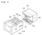
- FIG. 5 illustrates a second embodiment of the invention.
- each lock strip 32 of the retainer 30 is provided with the holding strips 34 holding the rear portion 24 of the housing 20 therebetween.
- each lock strip 132 of the retainer 130 has a central guide convex portion 137 projecting longer than the protrusions 133.
- Two guide protrusions 135 are formed on both sides of its distal end.
- the housing 120 has two guide grooves 129 each formed in the middle portion of each row of the cavities 122. Each guide protrusion 135 enters the corresponding guide groove 129.
- Each guide groove 129 has on its side walls guide concave portions 128 engaged with the respective guide protrusions 135.
- the guide protrusions 135 of the guide convex portion 137 are mated with the rear opening of the guide concave portions 128 of each guide groove 129, and the guide convex portions 137 are inserted into the respective guide grooves 129.
- the housing 120 is inserted into the retainer 130 until the positioning protrusions 136 engage the rear engagement apertures 127b of the housing 120 respectively, whereby the terminals are received in the respective cavities 122.
- the body 131 of the retainer 130 is advanced toward the housing 120.
- the guide protrusions 135 of the guide convex portions 137 move along the front end curved portions of the guide concave portions 128 and are drawn toward the vertically middle portion such that the protrusions 133 of the lock strips 132 invade the cavities 122 respectively, thereby engaging the respective terminals to hold them in position.
- the sides of the housing 120 are not covered by the respective lock strips 132, the sides of the housing 120 may be formed into different shapes, which improves the freedom in design.
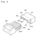
- FIG. 6 illustrates a third embodiment.
- the body 31 of the retainer 130 has such a cylindrical shape that the rear portion 24 of the housing 20 can be inserted into it so that the retainer 30 can be moved in parallel to the housing 20.
- horizontal grooves 228b are formed in the opposite sides of the housing 220 with the guide concave portions 128a.
- the body 231 of the retainer 230 has an open underside and the lower ends of the respective side walls thereof are bent inwardly so that protrusions 231a moved in parallel to the housing 220 in engagement with the respective grooves 228b are formed.
- the guide protrusions 235 of the holding strips 234 of the retainer 230 are mated with the guide concave portions 228a of the housing 220 respectively and the guide protrusions 235 are advanced in the respective guide concave portions 228a.
- the lower end protrusions 231a of the retainer body 231 are mated with the openings of the horizontal guide concave portions 228a respectively, and the retainer 230 is advanced to the housing 220.
- the positioning protrusions and the engagement apertures can be formed in the respective suitable portions although they are not shown in the figure.
- the connector has only a single row of terminal receiving cavities 222, it can be rendered small-sized when the cylindrical portion is eliminated in the retainer 230.
- the same central guide convex portion as that shown in FIG. 5 may be formed on the retainer body so as to be engaged with the guide groove and to be moved back and forth in parallel to the housing. Additionally, both the lock strip and the retainer body can be engaged with the housing when the guide convex portion has such a length that it is engaged only with the horizontal portion of the guide concave portion.
- the retainer comprises the body and the lock strips.
- the body is engaged with the housing so as to be moved in parallel thereto.
- Each lock strip is engaged with the housing so as to be moved toward and away from the housing when the retainer body is moved back and forth in parallel to the housing.
- the protrusions on each lock strip invade the respective terminal receiving cavities from the opening of the housing when each lock strip is moved toward the housing. Then, the protrusions are engaged with the terminals in the cavities to hold them in position respectively, thereby preventing them from backing out of the cavities.
- each arm of the retainer need not be flexed in the present invention although it is required to be flexed in the prior art connector as shown in FIGS. 9 and 10. Consequently, the operating force can be reduced and the assembly efficiency can be improved.
- Each lock strip is rendered horizontal and inclined with respect to the retainer body during operation of the connector. Consequently, the state of the retainer and the housing engaged with each other can readily be confirmed on the basis of the inclination of each lock strip.
- each lock strip When the retainer body is moved rearwardly, each lock strip is moved along the guide concave portion vertically outwardly relative to the housing. Accordingly, each lock strip reliably departs the housing and the protrusions of each lock strip also come out of the respective cavities. Consequently, pullout of the terminals is not prevented even after lapse of a long period of time.
Abstract
Description
- This invention relates to an electrical connector having cavities receiving terminals each of which has one end connected to a lead, and more particularly to such a connector employing a retainer providing double engagement for the terminals received in the cavities so that the terminals can be held in position therein.
- FIGS. 7 and 8 illustrate a conventional electrical connector employing the retainer providing double engagement for the terminals. FIGS. 9 and 10 illustrate another conventional connector employing such a retainer. Referring to FIGS. 7 and 8, the connector comprises a
housing 1 with a cylindrical cavities 1a receivingrespective terminals 2. Each cavity 1a has an open rear end through which theterminal 2 is inserted. A cap-shaped retainer 3 is fitted on an outer periphery of the rear end of thehousing 1. Theretainer 3 hasterminal insertion apertures 3a corresponding to the respective rear openings of the cavities 1a. Eachterminal insertion aperture 3a has aprotrusion 3b formed on the upper edge of the inner periphery thereof so that it protrudes toward the interior of the corresponding cavity 1a. When theretainer 3 is completely fitted on thehousing 1 as shown in FIG. 8, eachprotrusion 3b enters into the corresponding cavity 1a to collide with the rear end of theterminal 2. The state of thehousing 1 and theretainer 3 as shown in FIG. 8 will be referred to as "full engagement." - The
retainer 3 can be engaged with thehousing 1 before the full engagement state, assuming a position away upwardly from its position in the full engagement state, as shown in FIG. 7. In this position away upwardly from that in the full engagement state, eachprotrusion 3a is out of the corresponding cavity 1a and away upwardly therefrom. Accordingly, theprotrusions 3a do not interrupt theterminal 2 being inserted into the cavities 1a respectively. The state of thehousing 1 and theretainer 3 as shown in FIG. 7 will be referred to as "preliminary engagement." - In assembly of the above-described connector, the
terminals 2 are inserted into the cavities 1a from theterminal insertion apertures 3a respectively with thehousing 1 and theretainer 3 in the state of preliminary engagement. Forced down in the direction of arrow A in the preliminary engagement state as shown in FIG. 8, theretainer 3 is thrust in the direction of arrow B in FIG. 8. Thus, two-stage operation is necessitated in order that theretainer 3 is engaged with thehousing 1 in the full engagement state, that is, pushing theretainer 3 in the direction of arrow A and thrusting it in the direction of arrow B. The two-stage operation requires an operator to be well skilled in it, resulting in a problem in working efficiency. Furthermore, the two-stage operation prevents automatization of the terminal inserting work. - On the other hand, the connector shown in FIGS. 9 and 10 comprises a
housing 4 withcylindrical cavities 4a receivingterminals 5 respectively. A space or retainer receiving portion 4b is defined in a upper rear portion of eachcavity 4a for receiving aretainer 6. Theretainer 6 has in its distal end aflexible arm 6a and is inserted into the retainer receiving portion 4b from the side of thearm 6a. Theretainer 6 has arear end base 6a which is engageable at its top face with a ceiling face of the retainer receiving portion 4b. Theretainer 6 is engaged with the ceiling face of the retainer receiving portion 4b both when it assumes a preliminary engagement position where thebase 6a is not completely received in the retainer receiving portion 4b, as shown in FIG. 9 and when it assumes a full engagement position where it is completely received in the retainer receiving portion 4b. - The retainer receiving portion 4b has an inclined face 4c in its front end. The distal end of the
arm 6a is positioned at the side of the open end of the housing relative to the inclined face 4c when theretainer 6 is at the preliminary engagement position. When theretainer 6 is moved from the preliminary engagement position to the full engagement position, the distal end of thearm 6a is flexed downwardly along the inclined face 4c so that thearm 6a advances downwardly into thecavity 4a. - In assembly of the above-described connector, the
retainer 6 is inserted into the retainer receiving portion 4b from its side of thearm portion 6a such that theretainer 6 is engaged with the housing at the preliminary engagement position. Then, theterminals 5 are inserted into therespective cavities 4a and theretainer 6 is thrust in the direction of arrow C in FIG. 10 such that it is moved from the preliminary engagement position to the full engagement position. Thearm 6a of theretainer 6 then collides with the inclined face 4c to be flexed downwardly. Thearm 6a then collides with arecess 5a of theterminal 5 to push the same deep into thecavity 4a, thereby holding theterminals 5 received in therespective cavities 4a. - Since the
arm 6a is flexed when theretainer 6 is inserted into the retainer receiving portion 4b, the number of thearms 6a to be flexed is increased as the number of the terminals received in therespective cavities 4a is increased. Accordingly, a large operating force is necessary and results in reduction in the working efficiency. Furthermore, thearm 6a has lost its returning force when theretainer 6 is returned to the preliminary engagement position in inspection of the connector. In this case, thearm 6a remains flexed downwardly and accordingly, theterminal 5 cannot be pulled out. - Therefore, an object of the present invention is to provide an electrical connector which can be assembled readily and wherein the retainer can be guided by guide means with a simple construction and no structures are not provided on the outer face of the housing.
- The present invention provides an electrical connector comprising a housing having a plurality of cavities receiving a plurality of terminals therein respectively and a retainer engaged with the housing when assuming a full engagement position and a preliminary engagement position, the retainer having engagement strips invading the respective cavities, the engagement strips engaging the terminals in the cavities respectively to thereby hold the same in position when the retainer assumes the full engagement position, the engagement strips allowing insertion and pullout of the terminals when the retainer assumes the preliminary engagement position, characterized in that the housing has an opening communicating to the terminal receiving cavities and the retainer includes a body engaged with the housing and moved in parallel with the same and lock strips coupled to the body and bendable relative thereto, each lock strip being engaged with the housing through guide means and moving toward and away from the housing with the parallel movement of the body, each lock strip having protrusions disposed to face the opening of the housing, the protrusions moving into and out of the opening of the housing when the lock strips moving toward and away from the housing, the lock strips engaging the terminals received in the cavities respectively when having moved into the opening of the housing such that the terminals are held in position by the retainer.
- Each lock strip is moved toward or away from the housing by the guide means when the retainer is moved along the housing in the direction parallel to the same. In the case where each lock strip is moved toward the housing by the guide means when the body of the retainer is moved in one direction in parallel to the housing, the protrusions of the lock strips move into the cavities from the opening of the housing respectively. The protrusions are engaged with the respective terminals to hold them in position. On the other hand, when the retainer body is moved in the opposite direction, the lock strips are moved away from the housing by the guide means. The protrusions of the lock strips are caused to move out of the opening of the housing. Consequently, the terminals are disengaged from the respective protrusions of the lock strips and taken out.
- Since the protrusions of the lock strips are moved into and out of the housing with the movement of the retainer in the direction parallel to the housing, the connector can be assembled readily. Furthermore, since the lock strips are moved away from the housing by the guide means with the movement of the retainer even after lapse of time, pullout of the terminals is not prevented by the lock strips.
- The guide means may comprise a plurality of guide concave portions formed in the housing and a plurality of guide protrusions formed on the retainer and engaging the guide grooves respectively, each guide concave portion being curved so that the lock strip is drawn to the housing side in the parallel movement of the retainer.
- Each guide protrusion moves in the guide concave portion in engagement therewith when the retainer body is moved in parallel to the housing, so that each lock strip is moved toward and away from the housing along the curved concave portion. Alternatively, the guide concave portions may be formed in the retainer with the guide protrusions formed on the housing. Thus, the guide means can be achieved by a simple construction of the guide concave portions and the guide protrusions.
- The retainer may have two pairs of holding strips each pair holding the housing therebetween from the outside, the guide concave portions being formed in the holding strips, and the housing may have on opposite sides thereof sliding faces held by the holding strips, the guide protrusions being formed on the sliding faces.
- Since the holding strips are provided on the opposite side ends of each lock strip of the retainer for holding the housing, they are engaged with the housing at both sides of each lock strip. Each lock strip can stably be held at the housing side even when a load is applied to the protrusion of each lock strip.
- The housing may have a plurality of guide grooves extending in parallel to the direction of movement of the retainer, the guide concave portions being formed in the guide convex portions, and the retainer may have a plurality of guide convex portions inserted into the guide grooves of the housing respectively, the guide protrusions being formed on sliding faces of the guide groove.
- The guide concave portions of the retainer move into the respective guide grooves of the housing and further move in parallel to the housing. The lock strips of the retainer are moved toward and away from the housing by the guide concave portions and the guide protrusions engaged with the guide concave portions respectively. The guide concave portions and the guide protrusions may be provided either on the side of the guide grooves or the side of the guide convex portions. Since the guide convex portions are formed on the retainer side with the guide grooves formed in the housing side, the outer side face of the housing can be used for other purposes.
- The retainer may include a cylindrical portion into which the housing is inserted and the housing can be moved back and forth axially along the peripheral face of the cylindrical portion of the retainer. Since the retainer body is formed into the cylindrical shape, the retainer body can be moved back and forth axially along the housing in the direction parallel to the same. Consequently, the connector can be assembled readily only by insertion of the housing into the retainer.
- Furthermore, the retainer may have a plurality of sliding strips holding the housing therebetween from the outside thereof and the housing may have on the opposite sides slide faces, the sliding strips being moved back and forth sliding on the slide faces. Each sliding strip moves back and forth in the direction parallel 1 to the housing, sliding on the slide face. The retainer body has the guide means for engagement with the housing without the cylindrical portion, which improves the freedom of the configuration of the retainer or the connector.
- The invention will be described, merely by way of example, with reference to the accompanying drawings, in which:
- FIG. 1 is a perspective view of the electrical connector of a first embodiment in accordance with the invention with the retainer being separated from the housing;
- FIG. 2 is a partially broken front view of the connector with the retainer being separated from the housing;
- FIG. 3 is a partially broken front view of the connector in the preliminary engagement state;
- FIG. 4 is a partially broken front view of the connector in the full engagement state;
- FIG. 5 is a perspective view of the connector of a second embodiment with the retainer being separated from the housing;
- FIG. 6 is a perspective view of the connector of a third embodiment with the retainer being separated from the housing;
- FIG. 7 is a sectional view of a conventional connector with the retainer assuming the preliminary engagement position;
- FIG. 8 is a sectional view of the conventional connector with the retainer assuming the full engagement position;
- FIG. 9 is a sectional view of another conventional connector with the retainer assuming the preliminary engagement position; and
- FIG. 10 is a sectional view of the connector shown in FIG. 9 with the retainer assuming the full engagement position.
- A first embodiment of the present invention will be described with reference to FIGS. 1 to 4. In the embodiment, the invention is applied to a female connector.
- Referring to FIG. 1, an
electrical connector 10 comprises ahousing 20 generally formed into a rectangular parallelepiped and aretainer 30 attached to the rear end side of thehousing 20. A plurality ofterminals 40 each having an end connected to a lead by way of crimping are enclosed in the housing. - The interior of the
housing 20 is partitioned bypartition walls 21 into two rows of terminal receivingcavities 22, each row having four cavities. Thefront portion 23 of thehousing 20 closes the whole periphery of the terminal receivingcavities 22 while the top of the upper row of thecavities 22 and the bottom of the lower row of thecavities 20 are open in therear portion 24 of thehousing 20 such that anopening 22a is provided, as shown in FIG. 2. A front wall of thefront portion 23 havesmall apertures 25 through which male terminals (not shown) are inserted.Lock arms 26 are formed on the front end of the bottom of therear portion 24. Eachlock arm 26 can be flexed vertically. Eachlock arm 26 has anengagement protrusion 26a formed on the upper face thereof. Eachengagement protrusion 26a has such a configuration that it can be inserted into anengagement aperture 41 formed in the underside of each terminal 40 which will be described later, and held therein. - Two
engagement holes 27a are formed in the vertically middle portion of each of side walls of therear portion 24. Each side wall of the rear portion further has two groove-like guideconcave portions 28 extending from the rear end thereof toward the front end over and above theengagement holes 27a. Each guideconcave portion 28 extends generally horizontally from the rear end of therear portion 24 and is curved at itsfront end 28a toward the central portion. - The
retainer 30 includes abody 31 formed into a rectangular cylindrical shape and can enclose therear portion 24 of thehousing 20 therein. Two plate-shaped lock strips 32 are formed on the front portion of thebody 31. The lock strips 32 are connected to upper and lower walls of thebody 31 respectively. Eachlock strip 32 has a connection portion whose thickness is reduced such that it is bendable. Fourprotrusions 33 are formed on the inside face of eachlock strip 32 so as to correspond to each rows of thecavities 22. Two holdingstrips 34 are formed on the right-hand and left-hand ends of eachlock strip 32. Each holdingstrip 34 spreads toward the central side in the vertical direction. A space is defined between each holdingstrip 34 and its corresponding one so that therear portion 24 of thehousing 20 can be held therebetween. -
Guide protrusions 35 are formed on the inner sides of the holding strips 34 respectively. The guide protrusions 35 are engageable with the respective guideconcave portions 28 formed in therear portion 24 of thehousing 20. The guide protrusions 35 are so positioned that the lock strips 32 extends upwardly and downwardly respectively when inserted into the horizontal portions of the respective guideconcave portions 28. The guide protrusions 35 are further positioned so that eachlock strip 32 is drawn to be planer with thebody 31 when advancing forward along therespective grooves 28 to reach the front end curved portions. With the above-described movement of eachlock strip 32, theprotrusions 33 formed on the inner faces of the lock strips 32 invade thecavities 22 away from or near the rear openings thereof. The insertion of the terminals into therespective cavities 22 is not prevented by theprotrusions 33 in the condition that they are near the rear rear ends of thecavities 22. - Both side walls of the
body 31 has on their innerfaces positioning protrusions 36 respectively, which protrusions 36 are engageable with theengagement holes 27a formed in thehousing 20 respectively. Now consider the case where therear portion 24 of thehousing 20 is inserted into thebody 31 of theretainer 30 in the condition that theguide protrusions 35 of the holding strips 34 are in engagement with the respective guideconcave portions 28. In this state, theguide protrusions 35 are in the horizontal portions of the guideconcave portions 28 when thepositioning protrusions 36 are engaged with therear engagement holes 27a respectively. The guide protrusions 35 are in the curved front ends 28a of the guideconcave portions 28 when thepositioning protrusions 36 are engaged with thefront engagement holes 27a. The guide protrusions 36 in engagement with eachengagement hole 27a is disengaged there from when theretainer 30 is forced to move back and forth. - Each terminal 40 has at its front end a
cylindrical portion 42 for covering the respective male terminals for connection thereto. Each terminal 40 has at its rear end awire barrel 43 and aninsulation barrel 44 so that the lead wire of the wire W whose sheath of the end portion has been removed is crimped to be connected to therespective terminals 22. The above-describedengagement aperture 41 is formed the bottom of each terminal 40 near the rear end of thecylindrical portion 42. The upper face of therear end portion 42a of thecylindrical portion 42 is cut out. - The usage of the connector will be described. The wire sheath is removed from one end of each wire W and the end is crimped to the terminal 40 by the
wire barrel 43 and theinsulation barrel 44 beforehand. - Both lock strips 32 of the
retainer 30 are slightly spread and then, theretainer 30 is brought close to therear portion 24 of thehousing 20 from the rear side, as shown in FIG. 2. The guide protrusions 35 of the holding strips 34 are inserted into the rear end openings of the upper and lower guideconcave portions 28 respectively. In this state, therear portion 24 of thehousing 20 is inserted into thebody 31 of theretainer 30. - Since each guide
concave portion 28 is first horizontal, theguide protrusions 35 advances with eachlock strip 32 being spread. When each guideprotrusion 35 advances before the curved portion of the guideconcave portion 28, the positioningprotrusions 36 formed on the inner faces of thebody 31 are engaged with the rear endside engagement holes 27a on therear portion 24 of thehousing 20 respectively. Since thepositioning protrusions 36 are engaged with therespective engagement holes 27a in this state, thehousing 20 is prevented from being removed from theretainer 30. - In the above-described state,
terminals 40 are inserted into therespective cavities 22 from the side of thecylindrical portion 42. As described above, eachlock strip 32 remains in the spread state since theguide protrusions 35 of theretainer 30 are in engagement with the horizontal portions of the guideconcave portions 28 of thehousing 20 respectively. In this state, theprotrusions 33 are in therespective cavities 22 to be positioned slightly away from the upper orbottom opening 22a of thehousing 20. Accordingly, each terminal 40 can be inserted without colliding against theprotrusion 33. However, since theengagement protrusions 26a of thelock arms 26 protrude from the bottom of therespective cavities 20, each terminal 40 collides at its front end with theengagement protrusion 26a such that eachlock arm 26 is flexed downwardly and each terminal 40 is inserted deep into thecavity 22. Eachengagement protrusion 26a faces theengagement aperture 41 formed in the underside of the terminal 40 when it has reached the deepest portion of thecavity 22. A restoring force of thelock arm 26 pushes theengagement protrusion 26a up into theengagement aperture 41 such that the engagement protrusion is held in theengagement aperture 41. This state of theterminals 40 is shown by two dots chain line in FIG. 3. - The
body 31 of theretainer 30 is further advanced toward thehousing 20 when a necessary number ofterminals 40 are received in therespective cavities 22. The guide protrusions 35 of the holding strips 34 are positioned before the curved portions of the respective guideconcave portions 28 before advancement of theretainer body 31. Accordingly, with advancement, theguide protrusions 35 invade the portions of the guideconcave portions 28 curved to the vertically middle portion, respectively. The lock strips 32 come nearer to thehousing 20 via the holding strips 34 as theguide protrusions 35 advance toward the middle portion. With this movement of eachguide protrusion 35, theprotrusions 33 of eachlock strip 32 move from the rear to the front of thecavity 22 to go into it. - The distal end of each
lock strip 32 advances to the connection point of the front andrear portions guide protrusions 35 reach the front ends 28a of the respective guideconcave portions 28. Furthermore, theprotrusions 33 become parallel to thebody 31 and reaches the deepest of therespective cavities 22. Since thepositioning protrusions 36 of theretainer body 31 are engaged with thefront engagement holes 27a of thehousing 20 respectively, theretainer 30 and thehousing 20 can be prevented from being displaced. Theprotrusions 33 advance in therespective cavities 22 to collide with the upper facerear end portions 42a of thecylindrical portions 42 of theterminals 40 respectively. Accordingly, theunderside engagement hole 41 of each terminal 40 is engaged with theengagement protrusion 26a such that each terminal 40 is held in position. Furthermore, theprotrusion 33 of eachlock strip 32 collides with therear end portion 42a of eachcylindrical portion 42 such that each terminal 40 is also held in position. Thus, each terminal 40 is held in thecavity 22 by the double engagement structure. - A force pushing each terminal 40 rearwardly flexes each
lock strip 32 outwardly via theprotrusions 33. However, since thehousing 20 is held by the holding strips 34 of the lock strips 32, the lock strips 32 are stably drawn to thehousing 20 and accordingly, each terminal 40 can be prevented from being disengaged from theprotrusions 33. - There is a possibility that the
engagement hole 41 is not reliably engaged with thelock arm 26 when the terminal 40 is not inserted into the deepest of thecavity 22. In the embodiment, however, the protrusion of theretainer 30 collides with therear end portion 42a of thecylindrical portion 42 from the rear side. Consequently, the terminal 40 is pushed out to its normal position when it is not inserted into the deepest of thecavity 22 at first. - FIG. 5 illustrates a second embodiment of the invention. In the first embodiment, each
lock strip 32 of theretainer 30 is provided with the holding strips 34 holding therear portion 24 of thehousing 20 therebetween. In the second embodiment, eachlock strip 132 of theretainer 130 has a central guideconvex portion 137 projecting longer than the protrusions 133. Twoguide protrusions 135 are formed on both sides of its distal end. Furthermore, the housing 120 has twoguide grooves 129 each formed in the middle portion of each row of thecavities 122. Eachguide protrusion 135 enters thecorresponding guide groove 129. Eachguide groove 129 has on its side walls guideconcave portions 128 engaged with therespective guide protrusions 135. - In assembly, the
guide protrusions 135 of the guideconvex portion 137 are mated with the rear opening of the guideconcave portions 128 of eachguide groove 129, and the guideconvex portions 137 are inserted into therespective guide grooves 129. The housing 120 is inserted into theretainer 130 until the positioningprotrusions 136 engage therear engagement apertures 127b of the housing 120 respectively, whereby the terminals are received in therespective cavities 122. When the necessary number of terminals are received in therespective cavities 122, the body 131 of theretainer 130 is advanced toward the housing 120. The guide protrusions 135 of the guideconvex portions 137 move along the front end curved portions of the guideconcave portions 128 and are drawn toward the vertically middle portion such that the protrusions 133 of the lock strips 132 invade thecavities 122 respectively, thereby engaging the respective terminals to hold them in position. - Since the sides of the housing 120 are not covered by the respective lock strips 132, the sides of the housing 120 may be formed into different shapes, which improves the freedom in design.
- FIG. 6 illustrates a third embodiment. In the first embodiment, the
body 31 of theretainer 130 has such a cylindrical shape that therear portion 24 of thehousing 20 can be inserted into it so that theretainer 30 can be moved in parallel to thehousing 20. In the third embodiment,horizontal grooves 228b are formed in the opposite sides of thehousing 220 with the guide concave portions 128a. Thebody 231 of theretainer 230 has an open underside and the lower ends of the respective side walls thereof are bent inwardly so thatprotrusions 231a moved in parallel to thehousing 220 in engagement with therespective grooves 228b are formed. - In assembly, the
guide protrusions 235 of the holding strips 234 of theretainer 230 are mated with the guideconcave portions 228a of thehousing 220 respectively and theguide protrusions 235 are advanced in the respective guideconcave portions 228a. When the front end of theretainer body 231 comes close to the rear end of thehousing 220, thelower end protrusions 231a of theretainer body 231 are mated with the openings of the horizontal guideconcave portions 228a respectively, and theretainer 230 is advanced to thehousing 220. The positioning protrusions and the engagement apertures can be formed in the respective suitable portions although they are not shown in the figure. - In the case where the connector has only a single row of terminal receiving cavities 222, it can be rendered small-sized when the cylindrical portion is eliminated in the
retainer 230. In the third embodiment, too, the same central guide convex portion as that shown in FIG. 5 may be formed on the retainer body so as to be engaged with the guide groove and to be moved back and forth in parallel to the housing. Additionally, both the lock strip and the retainer body can be engaged with the housing when the guide convex portion has such a length that it is engaged only with the horizontal portion of the guide concave portion. - As obvious from the foregoing description, the retainer comprises the body and the lock strips. The body is engaged with the housing so as to be moved in parallel thereto. Each lock strip is engaged with the housing so as to be moved toward and away from the housing when the retainer body is moved back and forth in parallel to the housing. The protrusions on each lock strip invade the respective terminal receiving cavities from the opening of the housing when each lock strip is moved toward the housing. Then, the protrusions are engaged with the terminals in the cavities to hold them in position respectively, thereby preventing them from backing out of the cavities. In this regard, each arm of the retainer need not be flexed in the present invention although it is required to be flexed in the prior art connector as shown in FIGS. 9 and 10. Consequently, the operating force can be reduced and the assembly efficiency can be improved.
- In the condition that any one of the terminals is incompletely inserted in the cavity, the corresponding protrusion of the lock strip abuts against the upper face of the cylindrical portion of that terminal. Consequently, since the retainer is disallowed to be further moved forth, the incomplete insertion of the terminal in the cavity can be detected readily.
- Each lock strip is rendered horizontal and inclined with respect to the retainer body during operation of the connector. Consequently, the state of the retainer and the housing engaged with each other can readily be confirmed on the basis of the inclination of each lock strip.
- When the retainer body is moved rearwardly, each lock strip is moved along the guide concave portion vertically outwardly relative to the housing. Accordingly, each lock strip reliably departs the housing and the protrusions of each lock strip also come out of the respective cavities. Consequently, pullout of the terminals is not prevented even after lapse of a long period of time.
- Although the invention is applied to the female connector in the foregoing description, it may be applied to male connectors.
- The foregoing disclosure and drawings are merely illustrative of the principles of the present invention and are not to be interpreted in a limiting sense. The only limitation is to be determined from the scope of the appended claims.
Claims (6)
- An electrical connector comprising a housing (20) having a plurality of cavities (22) receiving a plurality of terminals (40) there in respectively and a retainer (30) engaged with the housing (20) when assuming a full engagement position and a preliminary engagement position, the retainer (30) having engagement strips (26) invading the respective cavities (22), the engagement strips (26) engaging the terminals (40) in the cavities (22) respectively to thereby hold the same in position when the retainer (30) assumes the full engagement position, the engagement strips (26) allowing insertion and pullout of the terminals (40) when the retainer (30) assumes the preliminary engagement position, characterized in that the housing has an opening communicating to the terminal receiving cavities (22) and the retainer (30) includes a body (31) engaged with the housing (20) and moved in parallel with the same and lock strips (32) coupled to the body (31) and bendable relative thereto, each lock strip (32) being engaged with the housing (20) through guide means and moving toward and away from the housing (20) with the parallel movement of the body (31), each lock strip (32) having protrusions (33) disposed to face the opening of the housing (20), the protrusions (33) moving into and out of the opening of the housing (20) when the lock strips (32) moving toward and away from the housing (20), the lock strips (32) engaging the terminals (40) received in the cavities (22) respectively when having moved into the opening of the housing (20) such that the terminals (40) are held in position by the retainer (30).
- An electrical connector according to claim 1, characterized in that the guide means comprises a plurality of guide concave portions (28) formed in the housing (20) and a plurality of guide protrusions (35) formed on the retainer (30) and engaging the guide concave portions (28) respectively, each guide concave portion (28) being curved so that the lock strip (32) is drawn to the housing side in the parallel movement of the retainer (30).
- An electrical connector according to claim 2, characterized in that the retainer (30) has two pairs of holding strips (34) each pair holding the housing (20) therebetween from the outside, that the guide concave portions (28) are formed in the holding strips (34), and that the housing (20) has on opposite sides thereof sliding faces held by the holding strips (34), the guide protrusions (35) being formed on the sliding faces.
- An electrical connector according to claim 2, characterized in that the housing (20) has a plurality of guide grooves (129) extending in parallel to the direction of movement of the retainer (30), that the retainer (30) has a plurality of guide convex portions (137) inserted into the guide grooves (129) of the housing (20) respectively, the guide concave portions (28) being formed in the guide convex portions (137), the guide protrusions (35) being formed on sliding faces of the guide grooves (129).
- An electrical connector according to claim 3 or 4, characterized in that the retainer (30) includes a cylindrical portion into which the housing (20) is inserted.
- An electrical connector according to claim 3 or 4, characterized in that the retainer (30) has a plurality of sliding strips holding the housing (20) therebetween from the outside thereof and that the housing (20) has on the opposite sides slide faces, the sliding strips being moved back and forth sliding on the slide faces.
Applications Claiming Priority (2)
| Application Number | Priority Date | Filing Date | Title |
|---|---|---|---|
| JP5045935A JPH06236777A (en) | 1993-02-10 | 1993-02-10 | Connector |
| JP45935/93 | 1993-02-10 |
Publications (3)
| Publication Number | Publication Date |
|---|---|
| EP0610855A2 true EP0610855A2 (en) | 1994-08-17 |
| EP0610855A3 EP0610855A3 (en) | 1995-08-16 |
| EP0610855B1 EP0610855B1 (en) | 1998-07-22 |
Family
ID=12733132
Family Applications (1)
| Application Number | Title | Priority Date | Filing Date |
|---|---|---|---|
| EP94101820A Expired - Lifetime EP0610855B1 (en) | 1993-02-10 | 1994-02-07 | Electrical connector with terminal retaining means |
Country Status (4)
| Country | Link |
|---|---|
| US (1) | US5435758A (en) |
| EP (1) | EP0610855B1 (en) |
| JP (1) | JPH06236777A (en) |
| DE (1) | DE69411772T2 (en) |
Cited By (3)
| Publication number | Priority date | Publication date | Assignee | Title |
|---|---|---|---|---|
| EP0772257A1 (en) * | 1995-11-02 | 1997-05-07 | Molex Incorporated | Electrical connector with terminal position assurance device that facilitates fully inserting a terminal |
| WO1997031407A1 (en) * | 1996-02-26 | 1997-08-28 | The Whitaker Corporation | An electrical connector having a pivot lock |
| WO2020164737A1 (en) * | 2019-02-15 | 2020-08-20 | Hirschmann Automotive Gmbh | Plug-in connector with improved protection against high-voltage flashovers |
Families Citing this family (12)
| Publication number | Priority date | Publication date | Assignee | Title |
|---|---|---|---|---|
| JP2604378Y2 (en) * | 1993-12-06 | 2000-05-08 | 矢崎総業株式会社 | Double locking connector with front holder |
| JP2800671B2 (en) * | 1993-12-09 | 1998-09-21 | 住友電装株式会社 | Temporary retainer for retainer |
| JP2857316B2 (en) * | 1994-04-15 | 1999-02-17 | 矢崎総業株式会社 | Connector waterproof cover |
| US5616048A (en) * | 1995-06-26 | 1997-04-01 | The Whitaker Corporation | Electrical connector with electrical contact and strain relief |
| US6106340A (en) * | 1998-04-30 | 2000-08-22 | The Whitaker Corporation | Electrical connector with deflectable secondary |
| JP2000048901A (en) * | 1998-07-27 | 2000-02-18 | Yazaki Corp | Water-proof connector |
| US7153172B2 (en) * | 2005-05-19 | 2006-12-26 | Deutsch Engineered Connecting Devices, Inc. | Fuel injector connector |
| WO2014160995A1 (en) * | 2013-03-29 | 2014-10-02 | Molex Incorporated | Connector with tpa |
| JP2016039100A (en) * | 2014-08-11 | 2016-03-22 | 住友電装株式会社 | Connector housing |
| US9484660B2 (en) * | 2014-11-13 | 2016-11-01 | Tyco Electronics Corporation | Electrical connector |
| JP2018190625A (en) * | 2017-05-09 | 2018-11-29 | 住友電装株式会社 | connector |
| JP7400640B2 (en) * | 2020-06-25 | 2023-12-19 | 株式会社オートネットワーク技術研究所 | connector |
Citations (2)
| Publication number | Priority date | Publication date | Assignee | Title |
|---|---|---|---|---|
| US5059142A (en) * | 1989-12-27 | 1991-10-22 | Yazaki Corporation | Electric connector with a terminal conductor detaining mechanism |
| EP0518361A2 (en) * | 1991-06-13 | 1992-12-16 | Yazaki Corporation | Electrical connector |
Family Cites Families (3)
| Publication number | Priority date | Publication date | Assignee | Title |
|---|---|---|---|---|
| GB2071926B (en) * | 1980-03-13 | 1984-02-08 | Labinal | Connector housing with contact retaining means |
| JPH0357027Y2 (en) * | 1988-05-06 | 1991-12-25 | ||
| JPH0740307Y2 (en) * | 1990-02-21 | 1995-09-13 | 矢崎総業株式会社 | Connector terminal locking device |
-
1993
- 1993-02-10 JP JP5045935A patent/JPH06236777A/en active Pending
-
1994
- 1994-02-07 DE DE69411772T patent/DE69411772T2/en not_active Expired - Fee Related
- 1994-02-07 EP EP94101820A patent/EP0610855B1/en not_active Expired - Lifetime
- 1994-02-09 US US08/194,001 patent/US5435758A/en not_active Expired - Fee Related
Patent Citations (2)
| Publication number | Priority date | Publication date | Assignee | Title |
|---|---|---|---|---|
| US5059142A (en) * | 1989-12-27 | 1991-10-22 | Yazaki Corporation | Electric connector with a terminal conductor detaining mechanism |
| EP0518361A2 (en) * | 1991-06-13 | 1992-12-16 | Yazaki Corporation | Electrical connector |
Cited By (4)
| Publication number | Priority date | Publication date | Assignee | Title |
|---|---|---|---|---|
| EP0772257A1 (en) * | 1995-11-02 | 1997-05-07 | Molex Incorporated | Electrical connector with terminal position assurance device that facilitates fully inserting a terminal |
| WO1997031407A1 (en) * | 1996-02-26 | 1997-08-28 | The Whitaker Corporation | An electrical connector having a pivot lock |
| AU715014B2 (en) * | 1996-02-26 | 2000-01-13 | Whitaker Corporation, The | An electrical connector having a pivot lock |
| WO2020164737A1 (en) * | 2019-02-15 | 2020-08-20 | Hirschmann Automotive Gmbh | Plug-in connector with improved protection against high-voltage flashovers |
Also Published As
| Publication number | Publication date |
|---|---|
| JPH06236777A (en) | 1994-08-23 |
| EP0610855B1 (en) | 1998-07-22 |
| DE69411772T2 (en) | 1999-02-04 |
| DE69411772D1 (en) | 1998-08-27 |
| US5435758A (en) | 1995-07-25 |
| EP0610855A3 (en) | 1995-08-16 |
Similar Documents
| Publication | Publication Date | Title |
|---|---|---|
| EP0610855B1 (en) | Electrical connector with terminal retaining means | |
| EP1139495B1 (en) | Insulator displacement stand and automatic insulation displacement machine | |
| US6638109B2 (en) | Connector with a side retainer | |
| JP3324690B2 (en) | connector | |
| EP0606903A2 (en) | Connector | |
| US5993268A (en) | Electrical connector with terminal retaining means | |
| US5474477A (en) | Method and apparatus for doubly securing a terminal within a connector | |
| EP0591950A2 (en) | Connector | |
| EP1863134B1 (en) | A connector | |
| JPH07211381A (en) | Locking method and structure for double locking connector | |
| EP1137118A2 (en) | A connector having at least one contact-pin inserting port for insertion of a conduction contact pin of a connector conduction-test tool | |
| EP1351339B1 (en) | A miniaturised connector | |
| US5860836A (en) | Contact which enables reliable discrimination of its orientation and connector using the same | |
| EP0646992B1 (en) | Electrical connector assembly with an improved operating lever | |
| US5904593A (en) | Connector with terminal retaining mechanism | |
| US6976874B2 (en) | Terminal fitting and connector provided therewith | |
| JP3247344B2 (en) | Connector housing and connector using the same | |
| US5562495A (en) | Electric connector | |
| US6589080B2 (en) | Terminal fitting and a connector | |
| JPS6264077A (en) | Electric connector | |
| US7001206B2 (en) | Connector and a connector assembly | |
| EP0147075B1 (en) | Connector having improved contact retainers | |
| US6000972A (en) | Structure for fixing terminal to connector housing | |
| US5810619A (en) | Double lock connector with flexible lance on spacer | |
| KR910006781Y1 (en) | Connector housing |
Legal Events
| Date | Code | Title | Description |
|---|---|---|---|
| PUAI | Public reference made under article 153(3) epc to a published international application that has entered the european phase |
Free format text: ORIGINAL CODE: 0009012 |
|
| AK | Designated contracting states |
Kind code of ref document: A2 Designated state(s): DE FR GB |
|
| PUAL | Search report despatched |
Free format text: ORIGINAL CODE: 0009013 |
|
| AK | Designated contracting states |
Kind code of ref document: A3 Designated state(s): DE FR GB |
|
| 17P | Request for examination filed |
Effective date: 19950926 |
|
| 17Q | First examination report despatched |
Effective date: 19960802 |
|
| GRAG | Despatch of communication of intention to grant |
Free format text: ORIGINAL CODE: EPIDOS AGRA |
|
| GRAG | Despatch of communication of intention to grant |
Free format text: ORIGINAL CODE: EPIDOS AGRA |
|
| GRAH | Despatch of communication of intention to grant a patent |
Free format text: ORIGINAL CODE: EPIDOS IGRA |
|
| GRAH | Despatch of communication of intention to grant a patent |
Free format text: ORIGINAL CODE: EPIDOS IGRA |
|
| GRAA | (expected) grant |
Free format text: ORIGINAL CODE: 0009210 |
|
| AK | Designated contracting states |
Kind code of ref document: B1 Designated state(s): DE FR GB |
|
| REF | Corresponds to: |
Ref document number: 69411772 Country of ref document: DE Date of ref document: 19980827 |
|
| ET | Fr: translation filed | ||
| PLBE | No opposition filed within time limit |
Free format text: ORIGINAL CODE: 0009261 |
|
| STAA | Information on the status of an ep patent application or granted ep patent |
Free format text: STATUS: NO OPPOSITION FILED WITHIN TIME LIMIT |
|
| 26N | No opposition filed | ||
| REG | Reference to a national code |
Ref country code: GB Ref legal event code: IF02 |
|
| PGFP | Annual fee paid to national office [announced via postgrant information from national office to epo] |
Ref country code: GB Payment date: 20020206 Year of fee payment: 9 |
|
| PGFP | Annual fee paid to national office [announced via postgrant information from national office to epo] |
Ref country code: FR Payment date: 20020212 Year of fee payment: 9 |
|
| PGFP | Annual fee paid to national office [announced via postgrant information from national office to epo] |
Ref country code: DE Payment date: 20020227 Year of fee payment: 9 |
|
| PG25 | Lapsed in a contracting state [announced via postgrant information from national office to epo] |
Ref country code: GB Free format text: LAPSE BECAUSE OF NON-PAYMENT OF DUE FEES Effective date: 20030207 |
|
| PG25 | Lapsed in a contracting state [announced via postgrant information from national office to epo] |
Ref country code: DE Free format text: LAPSE BECAUSE OF NON-PAYMENT OF DUE FEES Effective date: 20030902 |
|
| GBPC | Gb: european patent ceased through non-payment of renewal fee | ||
| PG25 | Lapsed in a contracting state [announced via postgrant information from national office to epo] |
Ref country code: FR Free format text: LAPSE BECAUSE OF NON-PAYMENT OF DUE FEES Effective date: 20031031 |
|
| REG | Reference to a national code |
Ref country code: FR Ref legal event code: ST |