EP0610717B1 - Washing machine with quick assembly motor - Google Patents
Washing machine with quick assembly motor Download PDFInfo
- Publication number
- EP0610717B1 EP0610717B1 EP94101094A EP94101094A EP0610717B1 EP 0610717 B1 EP0610717 B1 EP 0610717B1 EP 94101094 A EP94101094 A EP 94101094A EP 94101094 A EP94101094 A EP 94101094A EP 0610717 B1 EP0610717 B1 EP 0610717B1
- Authority
- EP
- European Patent Office
- Prior art keywords
- motor
- tub
- support means
- washing machine
- integral
- Prior art date
- Legal status (The legal status is an assumption and is not a legal conclusion. Google has not performed a legal analysis and makes no representation as to the accuracy of the status listed.)
- Expired - Lifetime
Links
Images


Classifications
-
- D—TEXTILES; PAPER
- D06—TREATMENT OF TEXTILES OR THE LIKE; LAUNDERING; FLEXIBLE MATERIALS NOT OTHERWISE PROVIDED FOR
- D06F—LAUNDERING, DRYING, IRONING, PRESSING OR FOLDING TEXTILE ARTICLES
- D06F37/00—Details specific to washing machines covered by groups D06F21/00 - D06F25/00
- D06F37/20—Mountings, e.g. resilient mountings, for the rotary receptacle, motor, tub or casing; Preventing or damping vibrations
- D06F37/206—Mounting of motor
Definitions
- This invention refer to a washing machine, specifically a laundry washing machine.
- the transmission belt is assembled and as a final step belt tension adjusted by positioning the motor correctly, generally using proper slot in the supports.
- this solution involves a high amount of vibrations being transmitted to the washing tub.
- Purpose of the invention is to provide a washing machine, specifically a laundry washer, allowing an easier and faster motor assembly, thus reducing the number of parts required and of operations to be carried out.
- no. 1 refers to the laundry washer motor as a whole according to the invention
- no. 2 refers to the rear cap of motor 1
- no. 3 shows a support integral to cap 2; said support 3 is used to hook and hold the motor 1 from the rear side through a pin (14 - Fig. 2) fastened to the machine tub.
- the support 3 has a shaped section to accommodate a cylindrical rubber pad 4 for motor 1 vibrations absorption.
- No. 5 refers to the front cap of motor 1; said cap is provided with two side supports 6.
- No. 7 refers to rubber pads inside the side supports 6 for motor stabilisation against static, reverse and operating torques.
- the rubber pads 7 are dimensioned and their relevant material selected not only to absorb vibrations but also keep the sheave-motor axle-distance within a range to ensure motion transmission by the belt (15-figs. 3 and 4); said belt is flexible to balance small deviations from the nominal value.
- no. 10 shows the machine tub lower section according to the present invention, e.g. in stainless steel, on which supports 11 and a support 12 for motor 1 are provided; as best seen in the partial section of A in Fig. 2 the supports 11 are shaped and have cylindrical indentations to accommodate the upper part of the rubber pads 7 to hinder motion.
- Support 12 has two side brackets 13, between which is located the cylindrical rubber pad 4 through a supporting pin 14 fastened between the two brackets 13.
- Fig. 3 illustrates schematically through a step sequence the assembly system on the tub 10 of motor 1; showing in particular the following four steps :
- rotation around pin 14 is constrained to have motor 1 in an easy position during assembly; in other words, the shape of the support 3 upper surface is suitably selected for the motor to be supported with an inclination allowing e.g. an easy assembly of the rubber pads 7 (Fig. 3 - part F3).
- the special shape of the support 3 allowing said constrained rotation, practically forms a sort of stop element hindering the motor 1 from falling down and/or striking the floor should the transmission belt 15 break.
- the washing machine according to the present invention offers the essential advantage of a particularly fast motor assembly and disassembly, without the use of tools.
- the supports 11 and support 12 may be shaped or moulded.
Landscapes
- Engineering & Computer Science (AREA)
- Textile Engineering (AREA)
- Main Body Construction Of Washing Machines And Laundry Dryers (AREA)
- Motor Or Generator Frames (AREA)
Description
- This invention refer to a washing machine, specifically a laundry washing machine.
- It is conventional practice to fasten a motor to the body of a laundry machine having both motor caps provided with supports on which rubber pads are assembled to absorb the vibrations caused by motor during operation; thereafter, spacers will be inserted into the rubber pads to avoid excessive compression when tightening the bolts to fasten the motor to the machine (generally to the tub).
- Subsequently the transmission belt is assembled and as a final step belt tension adjusted by positioning the motor correctly, generally using proper slot in the supports.
- From DE-A-4 026 549 a washing machine is known, where the motor is sustained by a transmission belt and comprises a rigid guide, which is inserted is a proper seat integral with an appendix of the rear cross member of the washing tub. In this solution, however, vibration and mechanical stresses between the two elements occur, with consequent noise during the machine operation; furthermore, the cited appendix involves a complication in the manufacturing step and reduces the available space within the machine cabinet.
- From FR-A-2 201 366 a washing machine is also known where the motor is pivoted at both sides to two supports, being integral with the tub; a spring must be provided, opposing its elastic force to the belt, with the purpose of guaranteeing the belt tension. This solution presents the disadvantage of employing a highly precompressed spring, that complicates to a high extent the motor assembly and disassembly operations, and it is dangerous by itself.
- Furthermore, this solution involves a high amount of vibrations being transmitted to the washing tub.
- Purpose of the invention is to provide a washing machine, specifically a laundry washer, allowing an easier and faster motor assembly, thus reducing the number of parts required and of operations to be carried out.
- Starting from FR-A-2 201 366 these aims are attained by a washing machine and a method for the motor assembly having the characterizing features of the annexed
claims 1 and 9. - The features and advantages of the machine according to the invention are detailed in the following description with reference to the annexed drawings, which are supplied only by way of non limiting example, where:
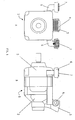
- Fig. 1 shows a schematic front view (A) and a side view (B) of the motor for a laundry washer according to the invention;
- Fig. 2 shows a schematic front view (A) and a side view (B) of the tub lower section in a laundry washer according to the invention;
- Fig. 3 is a schematic view of the motor assembly method of the laundry washer according to the invention;
- Fig. 4 is a perspective view of the assembled motor of the laundry washer according to the invention.
- In Fig. 1 reference no. 1 refers to the laundry washer motor as a whole according to the invention; no. 2 refers to the rear cap of
motor 1, whereas no. 3 shows a support integral tocap 2; saidsupport 3 is used to hook and hold themotor 1 from the rear side through a pin (14 - Fig. 2) fastened to the machine tub. - The
support 3 has a shaped section to accommodate acylindrical rubber pad 4 formotor 1 vibrations absorption. - No. 5 refers to the front cap of
motor 1; said cap is provided with two side supports 6. - No. 7 refers to rubber pads inside the side supports 6 for motor stabilisation against static, reverse and operating torques.
- The
rubber pads 7 are dimensioned and their relevant material selected not only to absorb vibrations but also keep the sheave-motor axle-distance within a range to ensure motion transmission by the belt (15-figs. 3 and 4); said belt is flexible to balance small deviations from the nominal value. - In fig. 2, no. 10 shows the machine tub lower section according to the present invention, e.g. in stainless steel, on which supports 11 and a
support 12 formotor 1 are provided; as best seen in the partial section of A in Fig. 2 thesupports 11 are shaped and have cylindrical indentations to accommodate the upper part of therubber pads 7 to hinder motion. -
Support 12 has twoside brackets 13, between which is located thecylindrical rubber pad 4 through a supportingpin 14 fastened between the twobrackets 13. - Fig. 3 illustrates schematically through a step sequence the assembly system on the
tub 10 ofmotor 1; showing in particular the following four steps : - Cycle F1 : motor alignment - during this step the shaped part of
support 3 oncap 2 is aligned with the supportingpin 14 bearing therubber pad 4; - Cycle F2 : motor insertion - during this step the
support 3 is hooked through its shaped section onto therubber pad 4 supported bypin 14; - Cycle F3 : front rubber pads assembly - during this step the
rubber pads 7 are assembled in thesupports 6 ofcap 5; this assembly step is simplified as motor 1 - already supported - can rotate constrained around thepin 14; - Cycle F4 : transmission belt assembly - during this step where final motor positioning is reached, a
flexible belt 15 is assembled between the motor and the drum sheave (not shown) of the laundry washer. - Following the above described assembly, the machine motor according to the present invention will appear as shown in Fig. 4.
- It should still be mentioned that rotation around
pin 14 is constrained to havemotor 1 in an easy position during assembly; in other words, the shape of thesupport 3 upper surface is suitably selected for the motor to be supported with an inclination allowing e.g. an easy assembly of the rubber pads 7 (Fig. 3 - part F3). - According to a further feature the special shape of the
support 3 allowing said constrained rotation, practically forms a sort of stop element hindering themotor 1 from falling down and/or striking the floor should thetransmission belt 15 break. - According to the above description the features and advantages of the washing machine with simplified motor assembly disclosed by the present invention appear quite evident.
- As it results from said description, the washing machine according to the present invention offers the essential advantage of a particularly fast motor assembly and disassembly, without the use of tools.
- Obviously, the inventive principle unaffected, many modifications may be made to the constructive features of the machine described by way of example without departing from the innovative criteria of the invention; the same as it is also obvious that in the practical execution of the invention both the shape and dimensions of the components may vary and be replaced by technically equivalent elements.
- As an example, in case of wash tubs in plastic material the
supports 11 andsupport 12 may be shaped or moulded.
Claims (9)
- Washing machine, specifically a laundry washing machine, comprising a tub and an electric motor (1), said motor (1) being coupled to support means (12) integral with a tub wall (10) and sustained in its front part by a transmission belt (15) extending from the motor (1) to a sheave, whereby rest means (6) are provided between the tub wall (10) and the motor (1) opposing the tension of the belt (15), characterized in that, in order to allow the assembly/disassembly of the motor (1) to the tub without the use of screw, rivets or other equivalent fastening means, or the use of tools:- said transmission belt (15) is of the flexible type, being able to balance small deviations from its nominal value,- said motor (1) is hooked only in its rear portion to said support means (12),- in the contact points between said rest means (6) and the tub wall (10) first rubber pads (7) are provided, for absorbing operating vibrations and keeping the sheave motor axle distance within a range which ensure the motion transmission by the belt.
- Washing machine, according to claim 1, characterized in that said support means integral with the tub (10) accommodates a second rubber pad (4), onto which said motor (1) is hooked.
- Washing machine, according to claim 1, characterized in that the rear cap (2) of the motor (1) comprises a hook shaped element (3).
- Washing machine, according to Claim 1, characterized in that said rest means (6) are integral with the front cap (5) of the motor (1) and define a seat for containing the lower section of said first rubber pads (7).
- Washing machine, according to Claim 1, characterized in that resting seats (11) are defined by said tub (10), for containing the upper section of said first rubber pads (7).
- Washing machine, according to at least one of the previous claims, characterized in that said resting seats (11) and/or said support means (12) are obtained by the moulding of a tub (10) realized in plastic material.
- Washing machine, according to claim 1, characterized in that the hooking system (3,12) between the motor (1) and the support means (12) is shaped for allowing a constrained rotation of said motor (1) around said support means (12).
- Washing machine, according to at least one of the previous claims, characterized in that said hook element (3) and/or said support means (12) are shaped for supporting the motor even in case of break of the transmission belt (15).
- Method for the assembly of an electric motor (1) to the tub (10) of a laundry washing machine without the use of screw, rivets or other equivalent fastening means, or the use of tools, whereby the motor (1) has to be coupled with support means (12) being integral with said tub (10) and sustained in its front part by a transmission belt (15), rest means (6) being arranged between the tub (10) and the motor (1) opposing the tension of the belt (15), characterized in that the following steps are provided:- an hooking element (3) integral with the rear part of the motor (1) is aligned with a support means (12) integral with the tub;- the hooking element (3) is coupled with the support means (12), in a way that the constrained rotation of the motor (1) is allowed around the support means (12);- the motor (1), while sustained by the support means (12), is rotated around the support means (12) till an inclined position;- when the motor (1) is in said inclined position, rubber pads (7) are mounted at the ends of the rest means (6);- the motor (1) is then rotated around said support means (12), till the rubber pads (7) come into contact with the tub wall (10);- a flexible transmission belt (15) is assembled between the motor (1) and the sheave.
Applications Claiming Priority (2)
| Application Number | Priority Date | Filing Date | Title |
|---|---|---|---|
| ITTO930069 | 1993-02-08 | ||
| ITTO930069A IT1264052B (en) | 1993-02-08 | 1993-02-08 | WASHING MACHINE WITH QUICK MOUNTING MOTOR |
Publications (2)
| Publication Number | Publication Date |
|---|---|
| EP0610717A1 EP0610717A1 (en) | 1994-08-17 |
| EP0610717B1 true EP0610717B1 (en) | 1997-09-17 |
Family
ID=11411079
Family Applications (1)
| Application Number | Title | Priority Date | Filing Date |
|---|---|---|---|
| EP94101094A Expired - Lifetime EP0610717B1 (en) | 1993-02-08 | 1994-01-26 | Washing machine with quick assembly motor |
Country Status (4)
| Country | Link |
|---|---|
| EP (1) | EP0610717B1 (en) |
| DE (1) | DE69405597T2 (en) |
| ES (1) | ES2110640T3 (en) |
| IT (1) | IT1264052B (en) |
Families Citing this family (5)
| Publication number | Priority date | Publication date | Assignee | Title |
|---|---|---|---|---|
| ES2154536B1 (en) * | 1998-02-19 | 2001-11-01 | Balay Sa | ENGINE HOLDING SYSTEM TO THE WASHER HUB. |
| ES2162530B1 (en) * | 1998-05-22 | 2002-08-01 | Balay Sa | WASHER MOTOR HOLDING SYSTEM TO THE CUBA. |
| DE602007001276D1 (en) * | 2006-03-30 | 2009-07-23 | Arcelik Anonim Sirketi Tuzla | WASHING MACHINE |
| DE102014218248A1 (en) * | 2014-09-11 | 2016-03-17 | BSH Hausgeräte GmbH | Motor arrangement in a laundry treatment appliance |
| KR20230173843A (en) * | 2022-06-20 | 2023-12-27 | 뉴모텍(주) | Motor for washing machine |
Family Cites Families (3)
| Publication number | Priority date | Publication date | Assignee | Title |
|---|---|---|---|---|
| DE1585611B1 (en) * | 1966-02-15 | 1971-09-16 | Constructa Werke Gmbh | Device for tensioning the rotary motion from the drive motor to the drive wheel of the washing and spinning drum of a washing machine |
| DE2248016C3 (en) * | 1972-09-29 | 1981-10-22 | Siemens AG, 1000 Berlin und 8000 München | Drum washing machine |
| DE4026549C2 (en) * | 1990-08-22 | 1995-05-24 | Bosch Siemens Hausgeraete | Front loading washing machine |
-
1993
- 1993-02-08 IT ITTO930069A patent/IT1264052B/en active IP Right Grant
-
1994
- 1994-01-26 ES ES94101094T patent/ES2110640T3/en not_active Expired - Lifetime
- 1994-01-26 DE DE69405597T patent/DE69405597T2/en not_active Expired - Fee Related
- 1994-01-26 EP EP94101094A patent/EP0610717B1/en not_active Expired - Lifetime
Also Published As
| Publication number | Publication date |
|---|---|
| EP0610717A1 (en) | 1994-08-17 |
| ITTO930069A0 (en) | 1993-02-08 |
| DE69405597T2 (en) | 1998-04-23 |
| ES2110640T3 (en) | 1998-02-16 |
| IT1264052B (en) | 1996-09-09 |
| DE69405597D1 (en) | 1997-10-23 |
| ITTO930069A1 (en) | 1994-08-08 |
Similar Documents
| Publication | Publication Date | Title |
|---|---|---|
| US4991412A (en) | Oscillatory support for drum washing machines | |
| US7744050B2 (en) | Self-leveling foot for an appliance | |
| US2647591A (en) | Vibration dampener | |
| JPH1043478A (en) | Washing machine with damping device | |
| JPH0898989A (en) | Automatic washing machine with vibration damping assembly | |
| US4625529A (en) | Laundry machines | |
| US2793757A (en) | Centrifugal-type washing machine | |
| NZ228572A (en) | Motor mounting assembly | |
| EP0610717A1 (en) | Washing machine with quick assembly motor | |
| US3475928A (en) | Clothes washing machine | |
| JPH1190086A (en) | Improvement of means for suspending washing assembly for electric washing machine | |
| KR100229630B1 (en) | Drum washing machine | |
| KR102845084B1 (en) | a Laundry Treatment Apparatus | |
| EP3924545A1 (en) | Vibration-reduced washing machine | |
| JP2911234B2 (en) | Drum type washing machine | |
| KR20040039049A (en) | Upholding device for washing machine | |
| EP0212259A2 (en) | Composite structure tub for a washing machine of the radial-loading type | |
| KR100195920B1 (en) | Apparatus for rotating prat support of drum type washing machine | |
| EP0896083B1 (en) | Improved elastic suspension means for the washing assembly of a washing machine | |
| KR20160102831A (en) | Damping apparatus for Owashing machine | |
| KR101014712B1 (en) | supporting apparatus in the washing machine | |
| KR102845085B1 (en) | a Laundry Treatment Apparatus | |
| KR102845082B1 (en) | a Laundry Treatment Apparatus | |
| KR100469250B1 (en) | structure for insulating vibration in the driving part of washing machine | |
| KR100233048B1 (en) | Dustproof Pulley Structure for Washing Machine |
Legal Events
| Date | Code | Title | Description |
|---|---|---|---|
| PUAI | Public reference made under article 153(3) epc to a published international application that has entered the european phase |
Free format text: ORIGINAL CODE: 0009012 |
|
| AK | Designated contracting states |
Kind code of ref document: A1 Designated state(s): BE DE ES FR GB IT NL SE |
|
| 17P | Request for examination filed |
Effective date: 19950208 |
|
| 17Q | First examination report despatched |
Effective date: 19960104 |
|
| GRAG | Despatch of communication of intention to grant |
Free format text: ORIGINAL CODE: EPIDOS AGRA |
|
| GRAH | Despatch of communication of intention to grant a patent |
Free format text: ORIGINAL CODE: EPIDOS IGRA |
|
| GRAH | Despatch of communication of intention to grant a patent |
Free format text: ORIGINAL CODE: EPIDOS IGRA |
|
| GRAA | (expected) grant |
Free format text: ORIGINAL CODE: 0009210 |
|
| AK | Designated contracting states |
Kind code of ref document: B1 Designated state(s): BE DE ES FR GB IT NL SE |
|
| PG25 | Lapsed in a contracting state [announced via postgrant information from national office to epo] |
Ref country code: IT Free format text: LAPSE BECAUSE OF FAILURE TO SUBMIT A TRANSLATION OF THE DESCRIPTION OR TO PAY THE FEE WITHIN THE PRESCRIBED TIME-LIMIT;WARNING: LAPSES OF ITALIAN PATENTS WITH EFFECTIVE DATE BEFORE 2007 MAY HAVE OCCURRED AT ANY TIME BEFORE 2007. THE CORRECT EFFECTIVE DATE MAY BE DIFFERENT FROM THE ONE RECORDED. Effective date: 19970917 |
|
| REF | Corresponds to: |
Ref document number: 69405597 Country of ref document: DE Date of ref document: 19971023 |
|
| ET | Fr: translation filed | ||
| REG | Reference to a national code |
Ref country code: ES Ref legal event code: FG2A Ref document number: 2110640 Country of ref document: ES Kind code of ref document: T3 |
|
| PLBE | No opposition filed within time limit |
Free format text: ORIGINAL CODE: 0009261 |
|
| STAA | Information on the status of an ep patent application or granted ep patent |
Free format text: STATUS: NO OPPOSITION FILED WITHIN TIME LIMIT |
|
| 26N | No opposition filed | ||
| REG | Reference to a national code |
Ref country code: GB Ref legal event code: IF02 |
|
| PGFP | Annual fee paid to national office [announced via postgrant information from national office to epo] |
Ref country code: ES Payment date: 20080122 Year of fee payment: 15 |
|
| PGFP | Annual fee paid to national office [announced via postgrant information from national office to epo] |
Ref country code: NL Payment date: 20080115 Year of fee payment: 15 Ref country code: GB Payment date: 20080109 Year of fee payment: 15 Ref country code: DE Payment date: 20080218 Year of fee payment: 15 Ref country code: SE Payment date: 20080114 Year of fee payment: 15 |
|
| PGFP | Annual fee paid to national office [announced via postgrant information from national office to epo] |
Ref country code: FR Payment date: 20080111 Year of fee payment: 15 |
|
| PGFP | Annual fee paid to national office [announced via postgrant information from national office to epo] |
Ref country code: BE Payment date: 20080115 Year of fee payment: 15 |
|
| EUG | Se: european patent has lapsed | ||
| GBPC | Gb: european patent ceased through non-payment of renewal fee |
Effective date: 20090126 |
|
| NLV4 | Nl: lapsed or anulled due to non-payment of the annual fee |
Effective date: 20090801 |
|
| PG25 | Lapsed in a contracting state [announced via postgrant information from national office to epo] |
Ref country code: DE Free format text: LAPSE BECAUSE OF NON-PAYMENT OF DUE FEES Effective date: 20090801 |
|
| REG | Reference to a national code |
Ref country code: FR Ref legal event code: ST Effective date: 20091030 |
|
| PG25 | Lapsed in a contracting state [announced via postgrant information from national office to epo] |
Ref country code: NL Free format text: LAPSE BECAUSE OF NON-PAYMENT OF DUE FEES Effective date: 20090801 Ref country code: GB Free format text: LAPSE BECAUSE OF NON-PAYMENT OF DUE FEES Effective date: 20090126 |
|
| PG25 | Lapsed in a contracting state [announced via postgrant information from national office to epo] |
Ref country code: BE Free format text: LAPSE BECAUSE OF NON-PAYMENT OF DUE FEES Effective date: 20090131 |
|
| REG | Reference to a national code |
Ref country code: ES Ref legal event code: FD2A Effective date: 20090127 |
|
| PG25 | Lapsed in a contracting state [announced via postgrant information from national office to epo] |
Ref country code: FR Free format text: LAPSE BECAUSE OF NON-PAYMENT OF DUE FEES Effective date: 20090202 Ref country code: ES Free format text: LAPSE BECAUSE OF NON-PAYMENT OF DUE FEES Effective date: 20090127 |
|
| PG25 | Lapsed in a contracting state [announced via postgrant information from national office to epo] |
Ref country code: SE Free format text: LAPSE BECAUSE OF NON-PAYMENT OF DUE FEES Effective date: 20090127 |