EP0610195B1 - Methode zur Steuerung einer Auslösesignalfolge in einem Schwungradmagnetzündesystem - Google Patents
Methode zur Steuerung einer Auslösesignalfolge in einem Schwungradmagnetzündesystem Download PDFInfo
- Publication number
- EP0610195B1 EP0610195B1 EP92908541A EP92908541A EP0610195B1 EP 0610195 B1 EP0610195 B1 EP 0610195B1 EP 92908541 A EP92908541 A EP 92908541A EP 92908541 A EP92908541 A EP 92908541A EP 0610195 B1 EP0610195 B1 EP 0610195B1
- Authority
- EP
- European Patent Office
- Prior art keywords
- trigger
- triggering
- ignition
- point
- trigger pulse
- Prior art date
- Legal status (The legal status is an assumption and is not a legal conclusion. Google has not performed a legal analysis and makes no representation as to the accuracy of the status listed.)
- Expired - Lifetime
Links
Images
Classifications
-
- F—MECHANICAL ENGINEERING; LIGHTING; HEATING; WEAPONS; BLASTING
- F02—COMBUSTION ENGINES; HOT-GAS OR COMBUSTION-PRODUCT ENGINE PLANTS
- F02P—IGNITION, OTHER THAN COMPRESSION IGNITION, FOR INTERNAL-COMBUSTION ENGINES; TESTING OF IGNITION TIMING IN COMPRESSION-IGNITION ENGINES
- F02P5/00—Advancing or retarding ignition; Control therefor
- F02P5/04—Advancing or retarding ignition; Control therefor automatically, as a function of the working conditions of the engine or vehicle or of the atmospheric conditions
- F02P5/145—Advancing or retarding ignition; Control therefor automatically, as a function of the working conditions of the engine or vehicle or of the atmospheric conditions using electrical means
- F02P5/155—Analogue data processing
- F02P5/1553—Analogue data processing by determination of elapsed angle with reference to a particular point on the motor axle, dependent on specific conditions
- F02P5/1555—Analogue data processing by determination of elapsed angle with reference to a particular point on the motor axle, dependent on specific conditions using a continuous control, dependent on speed
-
- F—MECHANICAL ENGINEERING; LIGHTING; HEATING; WEAPONS; BLASTING
- F02—COMBUSTION ENGINES; HOT-GAS OR COMBUSTION-PRODUCT ENGINE PLANTS
- F02P—IGNITION, OTHER THAN COMPRESSION IGNITION, FOR INTERNAL-COMBUSTION ENGINES; TESTING OF IGNITION TIMING IN COMPRESSION-IGNITION ENGINES
- F02P5/00—Advancing or retarding ignition; Control therefor
- F02P5/04—Advancing or retarding ignition; Control therefor automatically, as a function of the working conditions of the engine or vehicle or of the atmospheric conditions
- F02P5/145—Advancing or retarding ignition; Control therefor automatically, as a function of the working conditions of the engine or vehicle or of the atmospheric conditions using electrical means
- F02P5/155—Analogue data processing
- F02P5/1553—Analogue data processing by determination of elapsed angle with reference to a particular point on the motor axle, dependent on specific conditions
- F02P5/1556—Analogue data processing by determination of elapsed angle with reference to a particular point on the motor axle, dependent on specific conditions using a stepped control, dependent on speed
-
- Y—GENERAL TAGGING OF NEW TECHNOLOGICAL DEVELOPMENTS; GENERAL TAGGING OF CROSS-SECTIONAL TECHNOLOGIES SPANNING OVER SEVERAL SECTIONS OF THE IPC; TECHNICAL SUBJECTS COVERED BY FORMER USPC CROSS-REFERENCE ART COLLECTIONS [XRACs] AND DIGESTS
- Y02—TECHNOLOGIES OR APPLICATIONS FOR MITIGATION OR ADAPTATION AGAINST CLIMATE CHANGE
- Y02T—CLIMATE CHANGE MITIGATION TECHNOLOGIES RELATED TO TRANSPORTATION
- Y02T10/00—Road transport of goods or passengers
- Y02T10/10—Internal combustion engine [ICE] based vehicles
- Y02T10/40—Engine management systems
Definitions
- the present invention relates to a method for controlling the trigger sequence in a flywheel magneto system, which system includes a magnet system for inducing a trigger pulse for a gate trigger current switch.
- Previously disclosed within the area of ignition circuit design is the arrangement in the primary ignition coil circuit of magneto ignition systems containing an ignition transformer of a gate trigger current switch, for example a thyristor or a transistor, which is caused to conduct at a specific ignition time, resulting in the induction of an ignition voltage in the secondary winding of the coil.
- a control circuit of this kind possibly containing a special trigger coil, is connected between the generator circuit and the control input to the gate trigger current switch.
- Such systems are previously disclosed, for example, through SE-B-357 032, SE-B-455 216, and SE-B-457 373. These previously disclosed systems are more or less complicated and contain sensing devices to control the release of the trigger at an appropriate ignition time.
- a flywheel magneto system of the kind mentioned above, in which the method in accordance with the invention can be applied comprises, for example, a flywheel with a magnet unit installed in the wheel, in which two or more magnetic poles lie on an outer or inner periphery.
- a low-retentivity unit consisting of one or more essentially radially oriented legs. Coils are then arranged around one or more of these legs for the purpose of receiving energy from the passing magnetic poles.
- One common method of executing such a unit is to install all the coils belonging to the ignition system and the other electrical components in such a way that only a single core leg carries the necessary coils.
- capacitor ignition systems are concerned specifically, it is customary to utilize the most energy-rich partial wave in the induced voltage for charging the ignition capacitor.
- the following partial wave is used in order to initiate the ignition sequence. This permits simple and inexpensive solutions, which make effective use of the available energy. Nevertheless, the partial wave used to start the ignition sequence, "triggering", is too narrow to provide an acceptable advance of the trigger point as the speed of rotation increases, which is desirable.
- the form of the pulse is also influenced by the delay caused by charging of the ignition capacitor.
- SE-B-457 373 One method of avoiding this problem is shown in the aforementioned SE-B-457 373. This procedure is less suitable, however, if the trigger-releasing coil is arranged around a core leg which is situated ahead of another core leg past which a magnetic pole moves. The reason for this is that the partial wave used in this case for a coil position of this kind is too indeterminate to produce an exact trigger point.
- Another method is to utilize the last partial pulse for capacitor charging and a pulse preceding it, the middle pulse, for triggering.
- This gives lower energy for charging the capacitor although in those cases in which this is acceptable, it does not produce the same disadvantages as the system described above, but rather a desired successive advance of the ignition time over the range from start-up to high speed.
- this displacement of the ignition point reduces in proportion to the increasing diameter of the orbital path on which the magnetic poles are arranged, if the dimensions of the magnetic pole are essentially retained.
- the invention described below compensates for this effect.
- the present invention relates to a simple and inexpensive method for controlling the triggering sequence in flywheel magneto system , whereby, as the speed of rotation increases, a successive displacement of the trigger point occurs, which involves an advance of the trigger sequence.
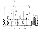
- Fig. 1 is a schematic representation of a circuit diagram for the control of the trigger sequence in accordance with the invention.
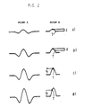
- Fig. 2 illustrates the form of the trigger pulse and the trigger point at successively increasing speeds of rotation.
- Fig. 1 shows a circuit diagram for a flywheel magneto system in which a charging winding 1 is so arranged as to interact through induction with a flywheel (not shown here) incorporating permanent magnets.
- the charging winding is connected in series to a rectifier, a diode 2, and a charging capacitor 3 and the primary winding 4 of an ignition transformer 5.
- the secondary winding 6 of the ignition transformer is connected to the spark gap of an ignition plug 7.
- a trigger winding 10 is also arranged in inductive connection with the flywheel.
- a rectifier diode 12, a further rectifier diode 13 and the emitter input terminal of a PNP transistor 14 are connected in series between the connection point A of the trigger winding 10 and the control input terminal 11 of the thyristor 9.
- a resistor 15 is connected between a connection point B in the connection between the two rectifier diodes 12 and 13.
- a Zener diode 16 is also connected between the connection point B and the base of the transistor 14.
- a trigger capacitor 17 is connected between the emitter of the transistor 14 and earth, and a resistor 18 is connected between the control input terminal 11 and earth.
- Fig. 2 illustrates the form of the trigger pulse at different speeds of rotation of the flywheel at the different points A and B in accordance with Fig. 1, and the trigger points T at these speeds of rotation.
- the function of the arrangement is as follows. As the flywheel rotates, a charging pulse is induced in the charging winding 1, which pulse is rectified by the diode 2 and charges the charging capacitor 3 in the usual way. Similarly induced is a trigger pulse, which is rectified by the diode 12. The rectified pulse charges the trigger capacitor 17. The voltage across the diode 13 is sensed, and as the voltage falls, indicating that the peak of the voltage has passed, the voltage across the diode 13 rises. When this voltage overcomes the Zener voltage Z in the Zener diode 16, the transistor 14 begins to conduct and in so doing discharges the trigger capacitor 17, whereby the thyristor 9 is triggered into a conducting state. The charging capacitor 3 is discharged in a familiar fashion, causing a surge of current through the primary winding 4 and producing a sufficiently high ignition voltage across the spark gap electrode 7.
- the form of the trigger pulse changes as the speed of rotation increases, i.e. the amplitude increases in line with the pattern shown in Fig. 2a-2d.
- Fig. 2a shows the appearance of the trigger pulse at the point A and the point B when the speed of rotation is low.
- the trigger point T occurs when the voltage at the point B has fallen from the highest level of the trigger pulse to a specified level Z. Triggering will start "late” if a relatively large value is selected for Z.
- Fig. 2b illustrates the situation once the speed of rotation has increased.
- the amplitude of the trigger pulse has now increased, and the trigger point T has been displaced to the left on the curve, with the result that triggering occurs earlier than shown in Fig. 2a.
- the peak of the trigger pulse to be at a level twice as high as the difference in level Z required for triggering, or even higher. Further triggering may occur at these levels. Since the capacitor charging of the ignition system has not yet achieved the correct level for reliable ignition, the diac 8, which requires a certain voltage level to be reached in order to permit a current to start to pass, is connected in series with the gate trigger current switch 9. The risk of undesired triggering is eliminated in this way.
- Figs. 2c and 2d show the trigger pulse at the points A and B after the speed of rotation has increased further, when the amplitude of the pulse reaches the preset voltage level N, which is determined by the size of the resistor 15. Triggering will now take place when this level is reached, i.e. once the trigger point has been displaced further to the left on the curve, with the result that triggering occurs even earlier, which is desirable.
- the invention is not restricted to the illustrative embodiment described above.
- the invention is thus not restricted to capacitor ignition systems, or to ignition systems in which the trigger signal is induced in the same core leg as the ignition energy.
- the thyristor and the transistor can also be replaced by other components, of course.
- the gate trigger current switch can also be connected directly to the diode, the trigger capacitor and the Zener diode.
- the advantage of the system in accordance with the invention is that the method described provides for the total displacement of the ignition point of the desired size.
Landscapes
- Engineering & Computer Science (AREA)
- Signal Processing (AREA)
- Chemical & Material Sciences (AREA)
- Combustion & Propulsion (AREA)
- Mechanical Engineering (AREA)
- General Engineering & Computer Science (AREA)
- Ignition Installations For Internal Combustion Engines (AREA)
- Control Of Direct Current Motors (AREA)
- Electrical Control Of Ignition Timing (AREA)
Claims (3)
- Verfahren zur Steuerung der Triggerfolge in einem Schwungrad-Magnetsystem, welches ein Magnetsystem enthält zur Induzierung eines Triggerpulses für einen Gate-Trigger-Stromschalter,
dadurch gekennzeichnet, daß
das Triggern eingeleitet wird bei einer bestimmten Differenz im Spannungspegel nach dem höchsten Wert des Triggerpulses, wobei während die zunehmende Rotationsgeschwindigkeit eine zunehmende Amplitude im Triggerpuls verursacht, eine Verschiebung des Triggerpunktes T erreicht wird, welche ein Vorverschieben in der Zündfolge beinhaltet. - Verfahren nach Anspruch 1,
dadurch gekennzeichnet, daß
bei einer weiteren Zunahme der Rotationsgeschwindigkeit, von dem Punkt ab, an welchem die Amplitude des Triggerpulses einen vorbestimmten Pegel N erreicht, das Triggern nur eingeleitet wird, wenn der Triggerpuls den erwähnten vorbestimmten Pegel N passiert, was zu einer weiteren Verschiebung des Triggerpunktes T führt. - Verfahren nach Anspruch 1 oder 2,
dadurch gekennzeichnet, daß
zur Verhinderung von Triggerstörungen eine Anordnung (8), welche das Erreichen eines bestimmten Spannungspegels erfordert, um einen Strom hindurchzulassen, in Reihe mit dem Gate-Trigger-Stromschalter (9) angeschlossen ist.
Applications Claiming Priority (3)
| Application Number | Priority Date | Filing Date | Title |
|---|---|---|---|
| SE9101101 | 1991-04-12 | ||
| SE9101101A SE468292B (sv) | 1991-04-12 | 1991-04-12 | Saett att styra triggfoerlopp |
| PCT/SE1992/000195 WO1992018768A1 (en) | 1991-04-12 | 1992-03-27 | A method for controlling the trigger sequence in a flywheel magneto system |
Publications (2)
| Publication Number | Publication Date |
|---|---|
| EP0610195A1 EP0610195A1 (de) | 1994-08-17 |
| EP0610195B1 true EP0610195B1 (de) | 1996-06-05 |
Family
ID=20382445
Family Applications (1)
| Application Number | Title | Priority Date | Filing Date |
|---|---|---|---|
| EP92908541A Expired - Lifetime EP0610195B1 (de) | 1991-04-12 | 1992-03-27 | Methode zur Steuerung einer Auslösesignalfolge in einem Schwungradmagnetzündesystem |
Country Status (6)
| Country | Link |
|---|---|
| US (1) | US5419295A (de) |
| EP (1) | EP0610195B1 (de) |
| JP (1) | JPH06506516A (de) |
| DE (1) | DE69211353T2 (de) |
| SE (1) | SE468292B (de) |
| WO (1) | WO1992018768A1 (de) |
Families Citing this family (4)
| Publication number | Priority date | Publication date | Assignee | Title |
|---|---|---|---|---|
| DE19906391A1 (de) * | 1999-02-16 | 2000-08-17 | Bosch Gmbh Robert | Zündsteuervorrichtung und -verfahren |
| JP3748522B2 (ja) * | 2001-06-18 | 2006-02-22 | 三菱電機株式会社 | 内燃機関の制御システム |
| US6575134B1 (en) * | 2001-08-14 | 2003-06-10 | Jim Bowling | Electronic governor for a gasoline engine |
| JP3986006B2 (ja) * | 2002-07-11 | 2007-10-03 | 追浜工業株式会社 | 内燃機関の無接点点火装置 |
Family Cites Families (5)
| Publication number | Priority date | Publication date | Assignee | Title |
|---|---|---|---|---|
| US3722488A (en) * | 1971-03-22 | 1973-03-27 | T Swift | Capacitor discharge system |
| JPS5572655A (en) * | 1978-11-27 | 1980-05-31 | Honda Motor Co Ltd | Ignition time delay angle control device for internal combustion engine |
| SE441613B (sv) * | 1982-10-13 | 1985-10-21 | Electrolux Ab | Kontaktlost, overvarvningsskyddat tendsystem for forbrenningsmotorer |
| JPS611668U (ja) * | 1984-06-11 | 1986-01-08 | 株式会社共立 | 点火装置 |
| SE457373B (sv) * | 1986-03-14 | 1988-12-19 | Svenska Electromagneter | Anordning foer styrning av triggfoerlopp vid kondensatortaendsystem saerskilt foer foerbraenningsmotorer |
-
1991
- 1991-04-12 SE SE9101101A patent/SE468292B/xx not_active IP Right Cessation
-
1992
- 1992-03-27 DE DE69211353T patent/DE69211353T2/de not_active Expired - Fee Related
- 1992-03-27 US US08/129,132 patent/US5419295A/en not_active Expired - Fee Related
- 1992-03-27 JP JP4508091A patent/JPH06506516A/ja active Pending
- 1992-03-27 EP EP92908541A patent/EP0610195B1/de not_active Expired - Lifetime
- 1992-03-27 WO PCT/SE1992/000195 patent/WO1992018768A1/en not_active Ceased
Also Published As
| Publication number | Publication date |
|---|---|
| SE9101101D0 (sv) | 1991-04-12 |
| DE69211353D1 (de) | 1996-07-11 |
| SE9101101L (sv) | 1992-10-13 |
| EP0610195A1 (de) | 1994-08-17 |
| JPH06506516A (ja) | 1994-07-21 |
| WO1992018768A1 (en) | 1992-10-29 |
| DE69211353T2 (de) | 1996-10-10 |
| SE468292B (sv) | 1992-12-07 |
| US5419295A (en) | 1995-05-30 |
Similar Documents
| Publication | Publication Date | Title |
|---|---|---|
| US3447521A (en) | Breakerless ignition system with automatic spark advance using triggering coil | |
| US3963015A (en) | Simplified automatic advance ignition system for an internal combustion engine | |
| US4404940A (en) | Engine speed limiting circuit | |
| US5069193A (en) | Ignition process, arangement and apparatus for internal combustion engines with a magneto | |
| US3545420A (en) | Capacitor discharge ignition system | |
| US4202305A (en) | Capacitor discharge ignition system with timing stabilization arrangement | |
| US3661132A (en) | Ignition circuit with automatic spark advance | |
| US4325350A (en) | Alternator-powered breakerless capacitor discharge ignition system having improved low-speed timing characteristics | |
| EP0434418B1 (de) | Drehzahlbegrenzer für Innenbrennkraftmaschinen | |
| US4174697A (en) | System for advancing the ignition time in ignition systems having a magneto generator | |
| EP0610195B1 (de) | Methode zur Steuerung einer Auslösesignalfolge in einem Schwungradmagnetzündesystem | |
| US3941111A (en) | Ignition system | |
| JPS58124069A (ja) | マグネト発電機を有する内燃機関の点火装置 | |
| EP0681651B1 (de) | Zündsystem für eine innere brennkraftmachine, insbesondere zum gebrauch in einer kettensäge oder ähnlicher maschine | |
| US4449497A (en) | Capacitor discharge ignition system | |
| US4562811A (en) | Ignition circuit | |
| US4949696A (en) | Capacitor ignition systems | |
| GB2253009A (en) | Breakerless i.c. engine ignition system with electronic advance | |
| US3791363A (en) | Electronically controlled reversal-proof magneto ignition system | |
| EP0243330A2 (de) | Vorrichtung in Zündsystemen | |
| US5025498A (en) | Apparatus for controlling the trigger sequence in ignition systems | |
| US4184467A (en) | Contactless ignition system for internal combustion engine | |
| US4228780A (en) | Capacitor discharge ignition system with timing control arrangement | |
| US4351286A (en) | Coil assembly for an ignition system | |
| US4375794A (en) | External inductive solid state ignition system |
Legal Events
| Date | Code | Title | Description |
|---|---|---|---|
| PUAI | Public reference made under article 153(3) epc to a published international application that has entered the european phase |
Free format text: ORIGINAL CODE: 0009012 |
|
| 17P | Request for examination filed |
Effective date: 19931001 |
|
| AK | Designated contracting states |
Kind code of ref document: A1 Designated state(s): DE IT |
|
| 17Q | First examination report despatched |
Effective date: 19950704 |
|
| GRAH | Despatch of communication of intention to grant a patent |
Free format text: ORIGINAL CODE: EPIDOS IGRA |
|
| GRAA | (expected) grant |
Free format text: ORIGINAL CODE: 0009210 |
|
| AK | Designated contracting states |
Kind code of ref document: B1 Designated state(s): DE IT |
|
| REF | Corresponds to: |
Ref document number: 69211353 Country of ref document: DE Date of ref document: 19960711 |
|
| ITF | It: translation for a ep patent filed | ||
| PLBE | No opposition filed within time limit |
Free format text: ORIGINAL CODE: 0009261 |
|
| 26N | No opposition filed | ||
| PGFP | Annual fee paid to national office [announced via postgrant information from national office to epo] |
Ref country code: DE Payment date: 20020320 Year of fee payment: 11 |
|
| PG25 | Lapsed in a contracting state [announced via postgrant information from national office to epo] |
Ref country code: DE Free format text: LAPSE BECAUSE OF NON-PAYMENT OF DUE FEES Effective date: 20031001 |
|
| PG25 | Lapsed in a contracting state [announced via postgrant information from national office to epo] |
Ref country code: IT Free format text: LAPSE BECAUSE OF NON-PAYMENT OF DUE FEES;WARNING: LAPSES OF ITALIAN PATENTS WITH EFFECTIVE DATE BEFORE 2007 MAY HAVE OCCURRED AT ANY TIME BEFORE 2007. THE CORRECT EFFECTIVE DATE MAY BE DIFFERENT FROM THE ONE RECORDED. Effective date: 20050327 |