EP0609066B1 - Apparatus for continuously forcing an elongate and extrusile raw material into an extrusion pressure vessel - Google Patents
Apparatus for continuously forcing an elongate and extrusile raw material into an extrusion pressure vessel Download PDFInfo
- Publication number
- EP0609066B1 EP0609066B1 EP94300571A EP94300571A EP0609066B1 EP 0609066 B1 EP0609066 B1 EP 0609066B1 EP 94300571 A EP94300571 A EP 94300571A EP 94300571 A EP94300571 A EP 94300571A EP 0609066 B1 EP0609066 B1 EP 0609066B1
- Authority
- EP
- European Patent Office
- Prior art keywords
- propellers
- raw material
- propeller
- pressure vessel
- guide passage
- Prior art date
- Legal status (The legal status is an assumption and is not a legal conclusion. Google has not performed a legal analysis and makes no representation as to the accuracy of the status listed.)
- Expired - Lifetime
Links
Images

Classifications
-
- B—PERFORMING OPERATIONS; TRANSPORTING
- B21—MECHANICAL METAL-WORKING WITHOUT ESSENTIALLY REMOVING MATERIAL; PUNCHING METAL
- B21C—MANUFACTURE OF METAL SHEETS, WIRE, RODS, TUBES OR PROFILES, OTHERWISE THAN BY ROLLING; AUXILIARY OPERATIONS USED IN CONNECTION WITH METAL-WORKING WITHOUT ESSENTIALLY REMOVING MATERIAL
- B21C33/00—Feeding extrusion presses with metal to be extruded ; Loading the dummy block
- B21C33/006—Consecutive billets, e.g. billet profiles allowing air expulsion or bonding of billets
-
- B—PERFORMING OPERATIONS; TRANSPORTING
- B21—MECHANICAL METAL-WORKING WITHOUT ESSENTIALLY REMOVING MATERIAL; PUNCHING METAL
- B21D—WORKING OR PROCESSING OF SHEET METAL OR METAL TUBES, RODS OR PROFILES WITHOUT ESSENTIALLY REMOVING MATERIAL; PUNCHING METAL
- B21D43/00—Feeding, positioning or storing devices combined with, or arranged in, or specially adapted for use in connection with, apparatus for working or processing sheet metal, metal tubes or metal profiles; Associations therewith of cutting devices
- B21D43/006—Feeding elongated articles, such as tubes, bars, or profiles
-
- B—PERFORMING OPERATIONS; TRANSPORTING
- B21—MECHANICAL METAL-WORKING WITHOUT ESSENTIALLY REMOVING MATERIAL; PUNCHING METAL
- B21C—MANUFACTURE OF METAL SHEETS, WIRE, RODS, TUBES OR PROFILES, OTHERWISE THAN BY ROLLING; AUXILIARY OPERATIONS USED IN CONNECTION WITH METAL-WORKING WITHOUT ESSENTIALLY REMOVING MATERIAL
- B21C23/00—Extruding metal; Impact extrusion
- B21C23/005—Continuous extrusion starting from solid state material
-
- B—PERFORMING OPERATIONS; TRANSPORTING
- B21—MECHANICAL METAL-WORKING WITHOUT ESSENTIALLY REMOVING MATERIAL; PUNCHING METAL
- B21C—MANUFACTURE OF METAL SHEETS, WIRE, RODS, TUBES OR PROFILES, OTHERWISE THAN BY ROLLING; AUXILIARY OPERATIONS USED IN CONNECTION WITH METAL-WORKING WITHOUT ESSENTIALLY REMOVING MATERIAL
- B21C27/00—Containers for metal to be extruded
-
- B—PERFORMING OPERATIONS; TRANSPORTING
- B21—MECHANICAL METAL-WORKING WITHOUT ESSENTIALLY REMOVING MATERIAL; PUNCHING METAL
- B21C—MANUFACTURE OF METAL SHEETS, WIRE, RODS, TUBES OR PROFILES, OTHERWISE THAN BY ROLLING; AUXILIARY OPERATIONS USED IN CONNECTION WITH METAL-WORKING WITHOUT ESSENTIALLY REMOVING MATERIAL
- B21C33/00—Feeding extrusion presses with metal to be extruded ; Loading the dummy block
-
- B—PERFORMING OPERATIONS; TRANSPORTING
- B23—MACHINE TOOLS; METAL-WORKING NOT OTHERWISE PROVIDED FOR
- B23Q—DETAILS, COMPONENTS, OR ACCESSORIES FOR MACHINE TOOLS, e.g. ARRANGEMENTS FOR COPYING OR CONTROLLING; MACHINE TOOLS IN GENERAL CHARACTERISED BY THE CONSTRUCTION OF PARTICULAR DETAILS OR COMPONENTS; COMBINATIONS OR ASSOCIATIONS OF METAL-WORKING MACHINES, NOT DIRECTED TO A PARTICULAR RESULT
- B23Q7/00—Arrangements for handling work specially combined with or arranged in, or specially adapted for use in connection with, machine tools, e.g. for conveying, loading, positioning, discharging, sorting
- B23Q7/05—Arrangements for handling work specially combined with or arranged in, or specially adapted for use in connection with, machine tools, e.g. for conveying, loading, positioning, discharging, sorting by means of roller-ways
- B23Q7/055—Arrangements for handling work specially combined with or arranged in, or specially adapted for use in connection with, machine tools, e.g. for conveying, loading, positioning, discharging, sorting by means of roller-ways some of the rollers being driven
Definitions
- the present invention relates to an apparatus for continuously forcing an elongate raw material into an extrusion pressure vessel, wherein the raw material is a wire or rod of a metal such as aluminum which has to be extruded from the vessel in a continuous manner.
- the present inventor has therefore proposed a continuous extrusion system in which an elongate and extrusile aluminum raw material such as a wire or rod is continuously fed to a pressure vessel.
- the raw material is compressed in the vessel so as to be extruded through a die.
- Such a new system will be exemplified below in the preferred embodiments of the present invention.
- the extrusion pressure of the raw material is raised by the forcing thereof into the pressure vessel.
- the extrusion ratio, the nature and/or temperature of said raw material it has been possible that an extraordinarily high pressure must be imparted to the material which is being loaded. For example, it has sometimes been difficult for a pair of simple drive rollers to grip and forcibly push the material into the pressure vessel.
- An object of the present invention made in view of the drawbacks inherent in the prior art methods is therefore to provide a novel apparatus constructed such that an elongate and extrusile raw material can continuously be fed into a pressure vessel more forcibly than in the prior art apparatuses.
- An apparatus for continuously forcing a wire-shaped or rod-shaped elongate raw material into an extrusion pressure vessel in an extruder comprises: at least one first propeller and at least one second propeller; a guide passage through which the raw material advances, the guide passage having an axis and penetrating all the propellers; one or more helical biting edges which protrude into the guide passage and are formed along an inner periphery of each propeller at a predetermined lead angle so as to bite an outer periphery of the raw material; all the propellers being arranged in series at different positions along the axis, rotatable around the axis but undisplaceable relative to each other axially of the guide passage; and a drive mechanism for rotating the first and second propellers in opposite directions, wherein the helical biting edges are inclined such that the raw material is forced towards the pressure vessel by the propellers, notwithstanding the opposite directions in which the first and second propellers rotate.
- the number of the first propellers as well as the number of the second ones depend on how strong the raw material has to be thrust. These numbers may be the same as each other and 1, 2 or more, or alternatively may be different.
- the helical biting edges of the first and second propellers driven by the drive mechanism will bite the outer periphery of the extrusile raw material.
- screw driving system between the helical edges and the elongate raw material, whereby an extremely strong thrust is applied thereto towards the pressure vessel.
- the extrusile raw material is an aluminum alloy
- the helical biting edges are made of a hard material such as a hard metal ( i.e., cemented carbide ), a ceramics or the like.
- each propeller is not accompanied by any valleys or grooves disposed on its both sides.
- each rotating helical edge may preferably be shaped such that its middle portion protrudes relatively deeper into the guide passage than its end portions respectively facing an entrance and an exit of the guide passage.
- the drive mechanism is constructed such that its input gear units are in mesh with one another, and one of them being in mesh with a common pinion. As a prime mover drives the pinion to rotate, the latter will drive the input gear units so as to rotate the first and second propellers in unison but in opposite directions.
- first propellers are preferably combined with two or more second propellers so that each of the former is interposed between two of the latter and vice versa, in axial alignment.
- Gear teeth may be formed around and integral with the outer periphery of each propeller.
- First pinions firmly secured on a first shaft may be in mesh with the respective first propellers, whilst second pinions secured on a second shaft are in mesh with the second propellers.
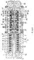
- the extruder 4 shown in Fig. 1 comprises a die 1, a pressure vessel 2 and a heater 3.
- the pressure vessel 2 is made of a material resistant to pressure and heat.
- a material includes a heat resisting steel, a ceramics and the like.
- a compressing chamber 5 formed in the pressure vessel 2 is tapered and gradually expanded towards an exit through which the raw material advances to be extruded.
- An entrance of the chamber 5 is an aperture 6 which fits on a raw material 'W' rod-shaped or wire-shaped and advancing into said chamber. Due to the tapered shape of the compressing chamber 5, the cross-sectional area of its entrance aperture 6 is smaller than that of its inner region.
- a nozzle 7 made of a hard material such as a hard metal, a ceramics or the like is fixed to the aperture 6 so that the raw material 'W' can be guided smooth into the chamber 5.
- a helical rib 15 of the shape of a square thread protrudes from the outer periphery of the pressure vessel 2, at a desired lead angle. This helical rib integral with said periphery raises the pressure resistance of the vessel 2, particularly in its radial direction.
- a helical groove composed of consecutive annular sections each defined between the adjacent annular ridges of the rib 15 is used as a spiral space 16 for accommodation of a heater. Basal portions or feet of the helical rib 15 may desirably be chamfered round as shown in Fig. 1, for a stronger junction to the body of the vessel.
- the heater 3 is capable of heating an extrusile block 'm' in the compressing chamber 5 to a temperature such that the block may be rendered less resistant to deformation during the extrusion process.
- the heater 3 is coiled around the pressure vessel 2 and extends helically through the spiral space 16 so as to surround the compressing chamber 5. Such an arrangement of the heater 3, which will make easier the construction thereof and a wiring operation therefor, is advantageous over a hypothetical case wherein a number of discrete annular recesses accommodate discrete heating elements.
- a first and second heater elements 10 and 11 constitute the heater 3, wherein the first one 10 extends along the pressure vessel and around an upstream region thereof near the entrance for the raw material 'W' for the high-frequency induction heating thereof.
- the second heater element 11 extends around a downstream region of the vessel and near the exit for the extrusile block 'm' for the middle- or low-frequency induction heating thereof.
- the first heater element 10 will heat the extrusile block 'm' sideways from its outer periphery so that a friction between it and the inner periphery of the compressing chamber 5 is lowered to easily receive the raw material 'W'.
- the second heater element 11 will evenly heat the block 'm' to a temperature at which its resistance to deformation is weakened for smooth extrusion.
- the heater 3 referred to above may be composed of a single heating element or otherwise composed.
- a heat-insulating layer 17 surrounding the pressure vessel 2 is held in a housing 18.
- the extruder of the described structure will operate as follows.
- the elongate raw material 'W' rod-shaped or wire-shaped may be an aluminum alloy such as those included in the A1000, A2000, A3000, A5000 or A6000 series.
- This material 'W' may not be the aluminum alloy but be any metallic material which is extrusile.
- the raw material 'W' may be of such a cross-sectional size that it can continuously be fed to the extruder which is running continuously.
- the size may preferably be such that the material 'W' can be stored in an arcuate and compacted state and be urged accurately into the compressing chamber 5 in order to serve as a continuously operating plunger.
- the material 'W' need not be round in cross section but may be of any other shape, a preferable example thereof is an aluminum round rod having a diameter of about 10 mm.
- the extrusile block 'm' made of the same substance as the raw material 'W' will be filled at first in the compressing chamber 5 of the pressure vessel 2, before starting the extrusion process. Both the heating elements 10 and 11 will then be activated to heat the block 'm' in the chamber 5 so that its deformation resistance is reduced to be ready for extrusion. Subsequently, the elongate raw material 'W' still solid at or above room temperature will be pressed into compressing chamber 5, through the nozzle 7 and the entrance 6 of the vessel 2. An apparatus 9 used to feed the material in this manner will be described below.
- the raw material 'W' having entered the chamber 5 through entrance 6 will smoothly advance a certain distance therein while being heated by the first heater element 10. A core portion of the material in this upstream region of the chamber remains solid, but a skin portion will be heated and softened. As the material 'W' further advances over the said distance into a down-stream region of said chamber, the second heater element 11 will further heat the material 'W' and render it less resistant to deformation, until it seems as if molten into and becomes integral with the extrusile block 'm' held in the chamber 5.
- Temperature of the extrusile block 'm' heated in the chamber 5 by the heater 3 does depend on the substance of which the block is made. In a case wherein the block 'm' is made of an aluminum alloy, it will be kept at, slightly above or below room temperature so that the portion of raw material 'W' remains solid near the entrance 6 while being thrust into the chamber. In the downstream region adjacent to the exit of the chamber 5, the block 'm' will preferably be heated for example to a temperature of about 400 - 650 ° C, which enables smooth extrusion through opening 1a of the die 1. A middle region between the entrance and the exit of the chamber 5 will be maintained for example at a temperature of about 400 - 600 ° C, whereby the material 'W' smoothly becomes integral with the material 'm'.
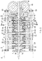
- the apparatus 9 is disposed in rear of and in close contact with the pressure vessel 2 as shown in Fig. 2, and comprises three first propellers 20, three second propellers 21 and a drive mechanism 22 designed to rotate these propellers.
- the reference numeral 18 denotes a pair of guide rollers, with the further numeral 19 denoting a stationary guide made of a hard material such as hard metal or ceramics.
- first and second propellers 20 and 21 are slightly different from one another, but are almost of the same structure. Therefore, only the first propellers 20 will be described here.
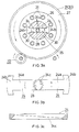
- each first propeller 20 comprises a pair of blades 24, a holder 25 for carrying the blades 24, an annular plate 26 for securing the blades in place, and a gear 27 secured to a periphery of the holder 25.
- These members 24 to 27 are fixedly combined with each other to form an assembly. This assembly can be dismantled to inexpensively replace the blades with new ones, when worn out or necessary to match a change in the kind of the raw material 'W'.
- a body 24a of each blade 24 is a strip whose basal end 24b is expanded sideways. Formed at a semicircular and convex inner end opposite to the basal end is a helical biting edge 24c.
- the blades 24 are made of a hard material such as a hard metal, ceramics or the like of a comparative hardness.
- biting edge 24c is a summit of a helically extending simple ridge when seen in cross section, and is not accompanied by any valley on either side. Deficiency of valleys is effective to protect the raw material 'W' from being jammed in part to lower the thrust applied thereto.
- two or more parallel edges ridge-shaped in cross section and accompanied by valleys therebetween may be formed at the end of each blade. Those valleys may however be rounded at their bottoms in order to diminish the possibility of jamming.
- the helical edges 24c protrude into a guide passage 28 through which the raw material advances. It is preferable that when seen in rotational direction illustrated in Fig. 3b each edge has an intermediate portion protruding deeper into the guide passage, than its leading and trailing end portions. Due to this configuration of the edges 24c, they can smoothly come into a biting engagement with the outer periphery of the raw material, and surely drive it forward before smoothly disengaging therefrom. Thus, the raw material will be transported in a smooth and reliable manner.
- the guide passage 28 for the raw material is formed through and axially of the holder 25, as shown in Figs. 2 and 3a.
- the holder 25 is preferably made of a hard material such as a hard metal, ceramics or the like so that the raw material 'W' can be in a smooth sliding contact with it and the durability of a bearing portion of the die 1 is ensured.
- Slots 30 are perforated through a portion of the holder 25 and adjacent to the flange 29.
- the slots 30 extend radially and are arranged at angular intervals of 180 ° and communicate with the guide passage 28 so that the blades 24 tightly fit in the slots.
- the blades 24 are thus inserted radially and inwardly into the respective slots 30, wherein their expanded ends 24b bear against the outer peripheral surface of the holder 25, with their helical edges 24c protruding a given distance into the guide passage 28, as shown in Fig. 3a.
- annular plate 26 which is bolted 31 to the flange 29 of holder 25, supports the outer surfaces of the expanded end 24b of each blade 24.
- the blades kept in place in this manner are undisplaceable in radial direction.
- the gear 27 has an axial bore 33 to receive the holder 25, and an annular flange 34 protruding inwardly into the bore.
- the flange 29 of the holder is laid on the annular flange 34 of the gear, and fastened thereto by means of the bolt 31, thereby firmly attaching the gear 27 to the holder 25.
- a short columnar lug 35 is formed to protrude centrally from one side of the holder 25, and a shallow cylindrical recess 36 is similarly and correspondingly formed on the other side of said holder. These lug 35 and recess 36 can be brought into a rotating engagement.
- the first propellers 20 are combined in series and coaxially with the second propellers 21.
- the first and second propellers alternate with one another so that they can rotate independently of each other.
- the lug 35 of the propeller 21 located most down-stream of the flow of the raw material is fitted in the shallow recess 7a of the nozzle 7 attached to the pressure vessel 2.
- the recess 36 of the propeller 20 located most upstream of the flow fits on a short columnar lug 19a of the stationary guide 19, thus holding in place all the propellers 20 and 21 between the guide 19 and the nozzle 7.
- first or second propellers 20 or 21 are elongate axially so that they are supported at their middle portions on a frame 40 by respective bearings 39.
- the reference numeral 41 denotes collars positioning the bearings.
- Cylindrical recesses 43 each formed on the inner peripheral surfaces of the connected first and second propellers 20 and 21, extend axially a considerable distance between the adjacent blade groups 24 disposed upstream and downstream of the material flow.
- Collars 44 which are fitted in the cylindrical recesses 43 and define some zones of the guide passage 28, are made of a less frictional substance so as to afford a smooth flow of the raw material.
- the guide passages 28 penetrating the connected first and second propellers 20 and 21 to form as a whole an integral passage whose inner wall is tapered for example at 1° - 2° to be slightly flared towards its exit.
- Such a design will be advantageous in reducing the friction between the passage wall and the raw material 'W' and thereby ensuring a smooth transportation thereof.
- the helical biting edges 24c of the blades 24 located downstream of the material flow through the guide passage 28 may protrude deeper there into than those located upstream of said flow. This design will prevent the edges from insufficiently bite the material due to any change in the state of its surface, which may possibly be softened due to friction or the like as it advances forward.
- the drive mechanism 22 comprises a pair of first and second shafts 45 and 46. These shafts, which are parallel with one another, extend along the series of first and second propellers 20 and 21 and in parallel with the advancing raw material. Each of the shafts 45 and 46 is supported on the frame 40 by ball bearings 50 and plain bearings 51.
- First pinions 47 are fixed to the periphery of the first shaft 45, at positions thereof corresponding to the first propellers 20.
- the first propellers 20 in mesh with the first pinions 47 will be driven to rotate in harmony and in the same direction.
- second pinions 48 are fixed to the periphery of the second shaft 46, at positions thereof corresponding to the second propellers 21.
- second propellers 21 in mesh with the second pinions 48 will also be driven to rotate in harmony and in the same direction.
- input gear units 52 and 53 are fixed to ends of the first and second shafts 45 and 46, respectively. These input gear units 52 and 53 are in mesh with one another, and a common pinion 54 engages with one of the gear units 52.
- the common pinion 54 is fixedly carried by a drive shaft 55, which in turn is operatively connected to an output shaft of a prime mover such as a not shown electric motor or an engine.
- the prime mover will be switched on to rotate the common pinion 54 and thus drive the input gear units 52 and 53 to rotate at the same speed but in opposite directions. Consequently, the first and second shafts 45 and 46 rotate at the same speed in the opposite directions to transmit the power to the first and second propellers 20 and 21, through the first and second pinions 47 and 48, respectively. As a result, all the first propellers 20 will rotate at the same speed but in a direction opposite to that in which the all the second propellers 21 rotate at the same speed.
- a plurality of the first propellers may preferably be rotated in a direction opposite to that in which another plurality of the second ones so do, in order to build an effective transmission.
- the helical biting edges 24c in the first propellers are of an ordinary pitch and those in the second ones are of a reverse pitch, or vice versa.
- the pair of feed rollers 18 will be activated to guide the raw material 'W' into the passage 28 formed through the first and second propellers 20 and 21.
- the pair of helical edges 24c in each of the propellers 20 and 21 will thus bite the periphery of said material 'W' and cooperate to push it towards the pressure vessel 2.
- a thrust which such a 'screw drive' mechanism will impart to the raw material 'W' is so strong that the internal pressure in the vessel 2 is readily raised to a sufficient level to enable the smooth extrusion of said material.
- the friction between the raw material 'W' and the passage through the apparatus 9 will raise the temperature of the material to such an extent as not to melt it but to reduce the heat energy which the heater 3 has to generate.
- the helical edges 24c in the first propellers will bite the raw material 'W' in a direction opposite to that in which the edges 24c in the second ones bite it. Therefore, the raw material is protected from torsion and undesirable spinning about its own axis, which torsion or spinning would otherwise impair the smooth feed of said material into the pressure vessel 2. It is an important feature in the illustrated embodiment that the blades in one propeller 20 or 21 and those in the next propeller 21 or 20 are disposed as close to one another as possible, in order to completely prevent the undesirable torsion or spinning of the raw material 'W'.
- first propellers 20 are combined with three second ones 21 in the embodiment, one of the former may be used with one of the latter, or alternatively much more first propellers may be employed together with much more second ones, depending on the required strength of thrust applied to the material.
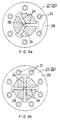
- each propeller in the embodiment, three or four blades may be built in each propeller, as shown in Figs. 5a and 5b.
- the apparatus provided herein to continuously force an elongate raw material into the pressure vessel, which material has to be subsequently extruded therefrom is constructed such that propellers each having a helical edge are rotated to cause their edges to bite the periphery of said material. Because a kind of 'screw drive' mechanism is effected when the propellers are driven, the material can forcibly and continuously be supplied surely to the vessel under a strong thrust. Thus, raw materials of any kind can now be extruded in a continuous manner, whereby feasibility of the continuous extrusion is remarkably improved.
- the raw material which is being fed to the extruder is well protected from unintentionally spining around its own axis or otherwise twisting, thereby affording a smoother feed of said material to the pressure vessel.
Landscapes
- Engineering & Computer Science (AREA)
- Mechanical Engineering (AREA)
- Extrusion Moulding Of Plastics Or The Like (AREA)
- Press-Shaping Or Shaping Using Conveyers (AREA)
- Noodles (AREA)
- Extrusion Of Metal (AREA)
- Meat, Egg Or Seafood Products (AREA)
Abstract
Description
- The present invention relates to an apparatus for continuously forcing an elongate raw material into an extrusion pressure vessel, wherein the raw material is a wire or rod of a metal such as aluminum which has to be extruded from the vessel in a continuous manner.
- For example in the case of extruding an aluminum material, it has been a common practice to repeat batch-wise steps, and in each step an aluminum billet is loaded in a container as the pressure vessel so as to be pressed through a die by a stem or ram which in turn is driven forward.
- However in such a batch-wise system, the repeated loading of the billets has been lowering the productivity of this process, and in some of the thus extruded products a discontinuity has occurred due to the transfer from the preceding billet to the succeeding one. The discontinuity has not only impaired the quality, but also caused a lower yield of said products in a case wherein the discontinuous portions were eliminated.
- The present inventor has therefore proposed a continuous extrusion system in which an elongate and extrusile aluminum raw material such as a wire or rod is continuously fed to a pressure vessel. The raw material is compressed in the vessel so as to be extruded through a die. Such a new system will be exemplified below in the preferred embodiments of the present invention.
- In the continuous extrusion system which was proposed by me, the extrusion pressure of the raw material is raised by the forcing thereof into the pressure vessel. Depending on the desired cross-sectional shape, the extrusion ratio, the nature and/or temperature of said raw material, it has been possible that an extraordinarily high pressure must be imparted to the material which is being loaded. For example, it has sometimes been difficult for a pair of simple drive rollers to grip and forcibly push the material into the pressure vessel.
- An object of the present invention made in view of the drawbacks inherent in the prior art methods is therefore to provide a novel apparatus constructed such that an elongate and extrusile raw material can continuously be fed into a pressure vessel more forcibly than in the prior art apparatuses.
- Other objects and advantages of the invention will become apparent from its preferred embodiments, which will be given below. merely for exemplary purpose
- An apparatus for continuously forcing a wire-shaped or rod-shaped elongate raw material into an extrusion pressure vessel in an extruder is provided herein to achieve the objects, wherein the apparatus comprises: at least one first propeller and at least one second propeller; a guide passage through which the raw material advances, the guide passage having an axis and penetrating all the propellers; one or more helical biting edges which protrude into the guide passage and are formed along an inner periphery of each propeller at a predetermined lead angle so as to bite an outer periphery of the raw material; all the propellers being arranged in series at different positions along the axis, rotatable around the axis but undisplaceable relative to each other axially of the guide passage; and a drive mechanism for rotating the first and second propellers in opposite directions, wherein the helical biting edges are inclined such that the raw material is forced towards the pressure vessel by the propellers, notwithstanding the opposite directions in which the first and second propellers rotate.
- The smaller is the lead angle of the helical biting edges, the stronger is the driving power of the propellers thrusting the raw material into the pressure vessel. It is however noted that the rotational speed of those propellers must be raised to meet a required feed speed of said raw material. Thus, the driving power should be set up and/or modified to be in a desirable relationship to the rotational speed, taking into account all the pertinent conditions, factors and requirements.
- The number of the first propellers as well as the number of the second ones depend on how strong the raw material has to be thrust. These numbers may be the same as each other and 1, 2 or more, or alternatively may be different.
- In operation of the apparatus provided herein to continuously feed the raw material, the helical biting edges of the first and second propellers driven by the drive mechanism will bite the outer periphery of the extrusile raw material. There will appear a kind of screw driving system between the helical edges and the elongate raw material, whereby an extremely strong thrust is applied thereto towards the pressure vessel.
- Further, since the first propellers rotate in a direction opposite to that in which the second ones so do, any disadvantage that the extrusile raw material will unintentionally rotate itself while advancing towards said vessel is avoided or diminished.
- It is preferable that if the extrusile raw material is an aluminum alloy, the helical biting edges are made of a hard material such as a hard metal ( i.e., cemented carbide ), a ceramics or the like.
- It is also preferable that the helical biting edge in each propeller is not accompanied by any valleys or grooves disposed on its both sides.
- Further, each rotating helical edge may preferably be shaped such that its middle portion protrudes relatively deeper into the guide passage than its end portions respectively facing an entrance and an exit of the guide passage.
- In a preferable embodiment, the drive mechanism is constructed such that its input gear units are in mesh with one another, and one of them being in mesh with a common pinion. As a prime mover drives the pinion to rotate, the latter will drive the input gear units so as to rotate the first and second propellers in unison but in opposite directions.
- In this arrangement of the drive mechanism, two or more first propellers are preferably combined with two or more second propellers so that each of the former is interposed between two of the latter and vice versa, in axial alignment. Gear teeth may be formed around and integral with the outer periphery of each propeller. First pinions firmly secured on a first shaft may be in mesh with the respective first propellers, whilst second pinions secured on a second shaft are in mesh with the second propellers.
- Thus, with one of the input gear units being driven, it will not only drive by the first shaft the first propellers but also drive the other input gear unit which in turn will similarly drive the second propellers.
-
- Fig. 1 is a cross section of an extruder which is provided with an apparatus for supplying thereto a raw material, with the apparatus constructed in an embodiment of the present invention;
- Fig. 2 is an enlarged cross section of the apparatus shown in Fig. 1;
- Fig. 3a is a cross section taken along the line 3 - 3 in Fig. 2:
- Fig. 3b is a plan view of blades installed in the apparatus;
- Fig. 3c is a front elevation of a helical biting edge shown partly in cross section and formed as an inner integral part of each blade;
- Fig. 4a is a front elevation of a transmission for drive means employed in the apparatus and shown partly in cross section;
- Fig. 4b is a side elevation of the transmission shown partly in cross section;
- Fig. 5a is a plan view of a modified arrangement of the blades, shown partly in cross section; and
- Fig. 5b is similarly a plan view of another modified arrangement of the blades, also shown partly in cross section.
- Now some embodiments of the present invention will be described in detail.
- An extruder in which an apparatus for forcing a raw material is installed will be outlined at first, with the description of the apparatus being given later.
- The
extruder 4 shown in Fig. 1 comprises a die 1, apressure vessel 2 and aheater 3. - The
pressure vessel 2 is made of a material resistant to pressure and heat. Such a material includes a heat resisting steel, a ceramics and the like. - A
compressing chamber 5 formed in thepressure vessel 2 is tapered and gradually expanded towards an exit through which the raw material advances to be extruded. An entrance of thechamber 5 is anaperture 6 which fits on a raw material 'W' rod-shaped or wire-shaped and advancing into said chamber. Due to the tapered shape of thecompressing chamber 5, the cross-sectional area of itsentrance aperture 6 is smaller than that of its inner region. - A
nozzle 7 made of a hard material such as a hard metal, a ceramics or the like is fixed to theaperture 6 so that the raw material 'W' can be guided smooth into thechamber 5. - A
helical rib 15 of the shape of a square thread protrudes from the outer periphery of thepressure vessel 2, at a desired lead angle. This helical rib integral with said periphery raises the pressure resistance of thevessel 2, particularly in its radial direction. A helical groove composed of consecutive annular sections each defined between the adjacent annular ridges of therib 15 is used as aspiral space 16 for accommodation of a heater. Basal portions or feet of thehelical rib 15 may desirably be chamfered round as shown in Fig. 1, for a stronger junction to the body of the vessel. - The
heater 3 is capable of heating an extrusile block 'm' in the compressingchamber 5 to a temperature such that the block may be rendered less resistant to deformation during the extrusion process. - The
heater 3 is coiled around thepressure vessel 2 and extends helically through thespiral space 16 so as to surround the compressingchamber 5. Such an arrangement of theheater 3, which will make easier the construction thereof and a wiring operation therefor, is advantageous over a hypothetical case wherein a number of discrete annular recesses accommodate discrete heating elements. - A first and
second heater elements heater 3, wherein thefirst one 10 extends along the pressure vessel and around an upstream region thereof near the entrance for the raw material 'W' for the high-frequency induction heating thereof. Thesecond heater element 11 extends around a downstream region of the vessel and near the exit for the extrusile block 'm' for the middle- or low-frequency induction heating thereof. - The
first heater element 10 will heat the extrusile block 'm' sideways from its outer periphery so that a friction between it and the inner periphery of the compressingchamber 5 is lowered to easily receive the raw material 'W'. On the other hand, thesecond heater element 11 will evenly heat the block 'm' to a temperature at which its resistance to deformation is weakened for smooth extrusion. Theheater 3 referred to above may be composed of a single heating element or otherwise composed. - A heat-insulating
layer 17 surrounding thepressure vessel 2 is held in ahousing 18. - The extruder of the described structure will operate as follows.
- The elongate raw material 'W' rod-shaped or wire-shaped may be an aluminum alloy such as those included in the A1000, A2000, A3000, A5000 or A6000 series. This material 'W' may not be the aluminum alloy but be any metallic material which is extrusile.
- The raw material 'W' may be of such a cross-sectional size that it can continuously be fed to the extruder which is running continuously. The size may preferably be such that the material 'W' can be stored in an arcuate and compacted state and be urged accurately into the compressing
chamber 5 in order to serve as a continuously operating plunger. Although the material 'W' need not be round in cross section but may be of any other shape, a preferable example thereof is an aluminum round rod having a diameter of about 10 mm. - The extrusile block 'm' made of the same substance as the raw material 'W' will be filled at first in the compressing
chamber 5 of thepressure vessel 2, before starting the extrusion process. Both theheating elements chamber 5 so that its deformation resistance is reduced to be ready for extrusion. Subsequently, the elongate raw material 'W' still solid at or above room temperature will be pressed into compressingchamber 5, through thenozzle 7 and theentrance 6 of thevessel 2. An apparatus 9 used to feed the material in this manner will be described below. - The raw material 'W' having entered the
chamber 5 throughentrance 6 will smoothly advance a certain distance therein while being heated by thefirst heater element 10. A core portion of the material in this upstream region of the chamber remains solid, but a skin portion will be heated and softened. As the material 'W' further advances over the said distance into a down-stream region of said chamber, thesecond heater element 11 will further heat the material 'W' and render it less resistant to deformation, until it seems as if molten into and becomes integral with the extrusile block 'm' held in thechamber 5. - Such a forcible and continuous feeding of the rod-or wire-shaped raw material 'W' will compress the
extrusile block 5 to be extruded through an opening 1a of the die 1, thereby forming an extruded product 'E' of a given cross-sectional shape. As will now be apparent, the elongate raw material 'W' act as if it were a plunger continuously driven within the compressingchamber 5, realizing a non-batchwise continuous extrusion. - Temperature of the extrusile block 'm' heated in the
chamber 5 by theheater 3 does depend on the substance of which the block is made. In a case wherein the block 'm' is made of an aluminum alloy, it will be kept at, slightly above or below room temperature so that the portion of raw material 'W' remains solid near theentrance 6 while being thrust into the chamber. In the downstream region adjacent to the exit of thechamber 5, the block 'm' will preferably be heated for example to a temperature of about 400 - 650 ° C, which enables smooth extrusion through opening 1a of the die 1. A middle region between the entrance and the exit of thechamber 5 will be maintained for example at a temperature of about 400 - 600 ° C, whereby the material 'W' smoothly becomes integral with the material 'm'. - The apparatus 9 forcing the raw material into and combined with the
extruder 4 as summarized above will now be described in detail. - The apparatus 9 is disposed in rear of and in close contact with the
pressure vessel 2 as shown in Fig. 2, and comprises threefirst propellers 20, threesecond propellers 21 and adrive mechanism 22 designed to rotate these propellers. Thereference numeral 18 denotes a pair of guide rollers, with thefurther numeral 19 denoting a stationary guide made of a hard material such as hard metal or ceramics. - Those first and
second propellers first propellers 20 will be described here. - As is shown in Figs. 2 and 3a, each
first propeller 20 comprises a pair ofblades 24, aholder 25 for carrying theblades 24, anannular plate 26 for securing the blades in place, and agear 27 secured to a periphery of theholder 25. Thesemembers 24 to 27 are fixedly combined with each other to form an assembly. This assembly can be dismantled to inexpensively replace the blades with new ones, when worn out or necessary to match a change in the kind of the raw material 'W'. - A
body 24a of eachblade 24 is a strip whosebasal end 24b is expanded sideways. Formed at a semicircular and convex inner end opposite to the basal end is a helicalbiting edge 24c. Theblades 24 are made of a hard material such as a hard metal, ceramics or the like of a comparative hardness. - As Fig. 3c shows, the biting
edge 24c is a summit of a helically extending simple ridge when seen in cross section, and is not accompanied by any valley on either side. Deficiency of valleys is effective to protect the raw material 'W' from being jammed in part to lower the thrust applied thereto. - If there is no serious problem of jamming, then two or more parallel edges ridge-shaped in cross section and accompanied by valleys therebetween may be formed at the end of each blade. Those valleys may however be rounded at their bottoms in order to diminish the possibility of jamming.
- The
helical edges 24c protrude into aguide passage 28 through which the raw material advances. It is preferable that when seen in rotational direction illustrated in Fig. 3b each edge has an intermediate portion protruding deeper into the guide passage, than its leading and trailing end portions. Due to this configuration of theedges 24c, they can smoothly come into a biting engagement with the outer periphery of the raw material, and surely drive it forward before smoothly disengaging therefrom. Thus, the raw material will be transported in a smooth and reliable manner. - The
guide passage 28 for the raw material is formed through and axially of theholder 25, as shown in Figs. 2 and 3a. Anannular flange 29, which is integral with the holder so as to secure thereto members mentioned below, protrudes radially and outwardly from a middle portion and in a direction of thickness of theholder 25. Theholder 25 is preferably made of a hard material such as a hard metal, ceramics or the like so that the raw material 'W' can be in a smooth sliding contact with it and the durability of a bearing portion of the die 1 is ensured. -
Slots 30 are perforated through a portion of theholder 25 and adjacent to theflange 29. Theslots 30 extend radially and are arranged at angular intervals of 180 ° and communicate with theguide passage 28 so that theblades 24 tightly fit in the slots. - The
blades 24 are thus inserted radially and inwardly into therespective slots 30, wherein their expanded ends 24b bear against the outer peripheral surface of theholder 25, with theirhelical edges 24c protruding a given distance into theguide passage 28, as shown in Fig. 3a. - The inner peripheral surface of
annular plate 26, which is bolted 31 to theflange 29 ofholder 25, supports the outer surfaces of the expandedend 24b of eachblade 24. The blades kept in place in this manner are undisplaceable in radial direction. - The
gear 27 has anaxial bore 33 to receive theholder 25, and anannular flange 34 protruding inwardly into the bore. Theflange 29 of the holder is laid on theannular flange 34 of the gear, and fastened thereto by means of thebolt 31, thereby firmly attaching thegear 27 to theholder 25. - A
short columnar lug 35 is formed to protrude centrally from one side of theholder 25, and a shallowcylindrical recess 36 is similarly and correspondingly formed on the other side of said holder. Theselug 35 andrecess 36 can be brought into a rotating engagement. - By engaging the
lugs 35 with the corresponding recesses 36, thefirst propellers 20 are combined in series and coaxially with thesecond propellers 21. Thus, the first and second propellers alternate with one another so that they can rotate independently of each other. - The
lug 35 of thepropeller 21 located most down-stream of the flow of the raw material is fitted in theshallow recess 7a of thenozzle 7 attached to thepressure vessel 2. On the other hand, therecess 36 of thepropeller 20 located most upstream of the flow fits on a shortcolumnar lug 19a of thestationary guide 19, thus holding in place all thepropellers guide 19 and thenozzle 7. - Some of the first or
second propellers frame 40 byrespective bearings 39. Thereference numeral 41 denotes collars positioning the bearings. - Cylindrical recesses 43, each formed on the inner peripheral surfaces of the connected first and
second propellers adjacent blade groups 24 disposed upstream and downstream of the material flow.Collars 44, which are fitted in thecylindrical recesses 43 and define some zones of theguide passage 28, are made of a less frictional substance so as to afford a smooth flow of the raw material. - It is preferable that the
guide passages 28 penetrating the connected first andsecond propellers - The helical biting edges 24c of the
blades 24 located downstream of the material flow through theguide passage 28 may protrude deeper there into than those located upstream of said flow. This design will prevent the edges from insufficiently bite the material due to any change in the state of its surface, which may possibly be softened due to friction or the like as it advances forward. - The
drive mechanism 22 comprises a pair of first andsecond shafts second propellers shafts frame 40 byball bearings 50 andplain bearings 51. - First pinions 47 are fixed to the periphery of the
first shaft 45, at positions thereof corresponding to thefirst propellers 20. Thefirst propellers 20 in mesh with thefirst pinions 47 will be driven to rotate in harmony and in the same direction. Similarly,second pinions 48 are fixed to the periphery of thesecond shaft 46, at positions thereof corresponding to thesecond propellers 21. Thus,second propellers 21 in mesh with the second pinions 48 will also be driven to rotate in harmony and in the same direction. - As Figs. 4a and 4b show,
input gear units second shafts input gear units common pinion 54 engages with one of thegear units 52. Thecommon pinion 54 is fixedly carried by adrive shaft 55, which in turn is operatively connected to an output shaft of a prime mover such as a not shown electric motor or an engine. - In operation of this
drive mechanism 22, the prime mover will be switched on to rotate thecommon pinion 54 and thus drive theinput gear units second shafts second propellers second pinions first propellers 20 will rotate at the same speed but in a direction opposite to that in which the all thesecond propellers 21 rotate at the same speed. - As is the case in this embodiment, a plurality of the first propellers may preferably be rotated in a direction opposite to that in which another plurality of the second ones so do, in order to build an effective transmission.
- Since the
first propellers 20 and thesecond ones 21 rotate in the opposite directions to thrust the raw material 'W' towards thepressure vessel 2, the helical bitingedges 24c in the first propellers are of an ordinary pitch and those in the second ones are of a reverse pitch, or vice versa. - In operation of the apparatus 9 for forcing the raw material into the pressure vessel, the pair of
feed rollers 18 will be activated to guide the raw material 'W' into thepassage 28 formed through the first andsecond propellers helical edges 24c in each of thepropellers pressure vessel 2. - A thrust which such a 'screw drive' mechanism will impart to the raw material 'W' is so strong that the internal pressure in the
vessel 2 is readily raised to a sufficient level to enable the smooth extrusion of said material. - The friction between the raw material 'W' and the passage through the apparatus 9 will raise the temperature of the material to such an extent as not to melt it but to reduce the heat energy which the
heater 3 has to generate. - It is to be noted that since the first and
second propellers helical edges 24c in the first propellers will bite the raw material 'W' in a direction opposite to that in which theedges 24c in the second ones bite it. Therefore, the raw material is protected from torsion and undesirable spinning about its own axis, which torsion or spinning would otherwise impair the smooth feed of said material into thepressure vessel 2. It is an important feature in the illustrated embodiment that the blades in onepropeller next propeller - Further, since the
input gear units shafts second propellers - Although three
first propellers 20 are combined with threesecond ones 21 in the embodiment, one of the former may be used with one of the latter, or alternatively much more first propellers may be employed together with much more second ones, depending on the required strength of thrust applied to the material. - In place of the two
blades 24 in each propeller in the embodiment, three or four blades may be built in each propeller, as shown in Figs. 5a and 5b. - In summary, the apparatus provided herein to continuously force an elongate raw material into the pressure vessel, which material has to be subsequently extruded therefrom, is constructed such that propellers each having a helical edge are rotated to cause their edges to bite the periphery of said material. Because a kind of 'screw drive' mechanism is effected when the propellers are driven, the material can forcibly and continuously be supplied surely to the vessel under a strong thrust. Thus, raw materials of any kind can now be extruded in a continuous manner, whereby feasibility of the continuous extrusion is remarkably improved.
- As already detailed above, since the first and second propellers rotate in opposite directions, the raw material which is being fed to the extruder is well protected from unintentionally spining around its own axis or otherwise twisting, thereby affording a smoother feed of said material to the pressure vessel.
Claims (6)
- An apparatus (9) for continuously forcing an elongate and extrusile raw material (W) into an extrusion pressure vessel (2) in an extruder (4), the raw material (W) being wire-shaped or rod-shaped, the apparatus (9) comprising:at least one first propeller (20) and at least one second propeller (21);a guide passage (28) through which the raw material (W) advances, the guide passage (28) having an axis and penetrating all the propellers (20,21);one or more helical biting edges (24c) which protrude into the guide passage (28) and are formed along an inner periphery of each propeller (20,21) at a predetermined lead angle so as to bite an outer periphery of the raw material (W);all the propellers (20,21) being arranged in series at different positions along the axis, rotatable around the axis but undisplaceable relative to each other axially of the guide passage (28); anda drive mechanism (22) for rotating the first and second propellers (20,21) in opposite directions, wherein the helical biting edges (24c) are inclined such that the raw material (W) is forced towards the pressure vessel (2) by the propellers (20,21), notwithstanding the opposite directions in which the first and second propellers (20,21) rotate.
- An apparatus as defined in claim 1, wherein the raw material (W) is made of an aluminum alloy, and the helical biting edges (24c) are made of a hard material selected from a group consisting of a hard metal, a ceramics and other substances substantially of the same hardness.
- An apparatus as defined in claim 1, wherein each helical biting edge (24c) in each propeller (20,21) is not accompanied by any valleys or grooves disposed on its both sides.
- An apparatus as defined in claim 1, wherein each helical biting edge (24c) is shaped such that its middle portion protrudes relatively deeper into the guide passage (28) than its end portions respectively facing an entrance and an exit of the guide passage (28).
- An apparatus as defined in claim 1, wherein the drive mechanism (22) is constructed such that its input gear units (52,53) are in mesh with one another, and one (52) of them being in mesh with a common pinion (54) so that the common pinion (54) driven by a prime mover drives the input gear units (52,53) so as to rotate the first and second propellers (20,21) in unison but in opposite directions.
- An apparatus as defined in claim 5, wherein two or more first propellers (20) are combined with two or more second propellers (21) so that each of the former is interposed between two of the latter and vice versa, in axial alignment, wherein gear teeth (27) are formed around and integral with the outer periphery of each propeller (20,21), and wherein first pinions (47) firmly secured on a first shaft (45) may be in mesh with the respective first propellers (20), whilst second pinions (48) secured on a second shaft (46) are in mesh with the second propellers (21) so that, with one (52) of the input gear units (52,53) being driven, it will not only drive the first propellers (20) through the first shaft (45) but also drive the other input gear unit (53) which in turn will similarly drive the second propellers (21) through the second shaft (46).
Applications Claiming Priority (2)
| Application Number | Priority Date | Filing Date | Title |
|---|---|---|---|
| JP13318/93 | 1993-01-29 | ||
| JP5013318A JP2564082B2 (en) | 1993-01-29 | 1993-01-29 | Continuous pushing and feeding device for long extrusion material into extrusion pressure vessel |
Publications (2)
| Publication Number | Publication Date |
|---|---|
| EP0609066A1 EP0609066A1 (en) | 1994-08-03 |
| EP0609066B1 true EP0609066B1 (en) | 1996-09-04 |
Family
ID=11829824
Family Applications (1)
| Application Number | Title | Priority Date | Filing Date |
|---|---|---|---|
| EP94300571A Expired - Lifetime EP0609066B1 (en) | 1993-01-29 | 1994-01-26 | Apparatus for continuously forcing an elongate and extrusile raw material into an extrusion pressure vessel |
Country Status (9)
| Country | Link |
|---|---|
| US (1) | US5473925A (en) |
| EP (1) | EP0609066B1 (en) |
| JP (1) | JP2564082B2 (en) |
| KR (1) | KR940018146A (en) |
| AT (1) | ATE142130T1 (en) |
| AU (1) | AU670651B2 (en) |
| CA (1) | CA2114453A1 (en) |
| DE (1) | DE69400444T2 (en) |
| TW (1) | TW237406B (en) |
Families Citing this family (9)
| Publication number | Priority date | Publication date | Assignee | Title |
|---|---|---|---|---|
| JP2602397B2 (en) * | 1993-03-04 | 1997-04-23 | 有限会社矢野エンジニアリング | Extrusion processing equipment |
| US5740688A (en) * | 1995-10-05 | 1998-04-21 | Sural Tech | Pressure-assisted formation of shaped articles |
| EP0839589A1 (en) * | 1996-11-04 | 1998-05-06 | Alusuisse Technology & Management AG | Method for producing a metallic profiled strand |
| EP1264646A1 (en) * | 2001-06-07 | 2002-12-11 | Alcan Technology & Management AG | Device and method for the manufacturing of profiled metal rods |
| TWI346514B (en) | 2007-06-05 | 2011-08-01 | Young Lighting Technology Corp | Back light module and light emitting diode package structure therefor |
| TWI462350B (en) | 2008-12-24 | 2014-11-21 | Ind Tech Res Inst | Light emitting device with multi-chips |
| TWI422073B (en) | 2010-05-26 | 2014-01-01 | Interlight Optotech Corp | Light emitting diode package structure |
| US9346089B2 (en) * | 2012-10-12 | 2016-05-24 | Manchester Copper Products, Llc | Extrusion press systems and methods |
| US9545653B2 (en) * | 2013-04-25 | 2017-01-17 | Manchester Copper Products, Llc | Extrusion press systems and methods |
Family Cites Families (2)
| Publication number | Priority date | Publication date | Assignee | Title |
|---|---|---|---|---|
| DE149170C (en) * | ||||
| US5167138A (en) * | 1987-12-31 | 1992-12-01 | Southwire Company | Conform extrusion process and apparatus |
-
1993
- 1993-01-29 JP JP5013318A patent/JP2564082B2/en not_active Expired - Lifetime
-
1994
- 1994-01-25 TW TW083100615A patent/TW237406B/zh active
- 1994-01-26 AT AT94300571T patent/ATE142130T1/en not_active IP Right Cessation
- 1994-01-26 EP EP94300571A patent/EP0609066B1/en not_active Expired - Lifetime
- 1994-01-26 DE DE69400444T patent/DE69400444T2/en not_active Expired - Fee Related
- 1994-01-27 KR KR1019940001507A patent/KR940018146A/en not_active Application Discontinuation
- 1994-01-28 AU AU54788/94A patent/AU670651B2/en not_active Ceased
- 1994-01-28 US US08/188,585 patent/US5473925A/en not_active Expired - Fee Related
- 1994-01-28 CA CA002114453A patent/CA2114453A1/en not_active Abandoned
Also Published As
| Publication number | Publication date |
|---|---|
| CA2114453A1 (en) | 1994-07-30 |
| EP0609066A1 (en) | 1994-08-03 |
| AU5478894A (en) | 1994-08-04 |
| JPH06226337A (en) | 1994-08-16 |
| JP2564082B2 (en) | 1996-12-18 |
| TW237406B (en) | 1995-01-01 |
| DE69400444T2 (en) | 1997-02-20 |
| AU670651B2 (en) | 1996-07-25 |
| KR940018146A (en) | 1994-08-16 |
| ATE142130T1 (en) | 1996-09-15 |
| DE69400444D1 (en) | 1996-10-10 |
| US5473925A (en) | 1995-12-12 |
Similar Documents
| Publication | Publication Date | Title |
|---|---|---|
| EP0609066B1 (en) | Apparatus for continuously forcing an elongate and extrusile raw material into an extrusion pressure vessel | |
| EP1095218B1 (en) | Internally profiled stator tube | |
| EP0144932B1 (en) | Method for extruding thermoplastic material | |
| EP0764074B1 (en) | Multi-screw, extrusion-compounding machine with modular mixing elements | |
| US4462692A (en) | Screw extruders | |
| US4678339A (en) | Screw extruder | |
| EP1888268B1 (en) | Laying head with multi-groove rotating member | |
| GB2102723A (en) | Method of an apparatus for forming grooves in an elongate body | |
| US4838700A (en) | Assemblies for a worm press | |
| US5304054A (en) | Plasticizing sections of cold feed rubber extruders | |
| EP0615796B1 (en) | Extruder | |
| US4094178A (en) | Methods for continuous extrusion | |
| EP0072207A1 (en) | Extrusion of copper | |
| US2051688A (en) | Apparatus for the extrusion of metal | |
| GB2202783A (en) | Extruder | |
| US4795599A (en) | Screw extruder and a method of operation thereof | |
| CN116867633A (en) | Method and apparatus for producing coiled tubing from thermoplastic material | |
| JP3589487B2 (en) | Viscous material extrusion equipment | |
| EP1057612B1 (en) | Extruder screw with internal axial bore for melt transport | |
| CN216443045U (en) | Full-automatic pipe forming machine for spiral winding pipe | |
| GB2208618A (en) | Continuous extrusion apparatus | |
| KR820000648B1 (en) | Apparatus for continous extrusion | |
| CN1562608A (en) | Portable minitype plastic extruding machine | |
| JP3348649B2 (en) | Rotary extrusion equipment | |
| SU372002A1 (en) | DEVICE FOR HAIRING ROUND PROFILES |
Legal Events
| Date | Code | Title | Description |
|---|---|---|---|
| PUAI | Public reference made under article 153(3) epc to a published international application that has entered the european phase |
Free format text: ORIGINAL CODE: 0009012 |
|
| AK | Designated contracting states |
Kind code of ref document: A1 Designated state(s): AT DE FR GB SE |
|
| 17P | Request for examination filed |
Effective date: 19940919 |
|
| 17Q | First examination report despatched |
Effective date: 19951017 |
|
| GRAH | Despatch of communication of intention to grant a patent |
Free format text: ORIGINAL CODE: EPIDOS IGRA |
|
| GRAH | Despatch of communication of intention to grant a patent |
Free format text: ORIGINAL CODE: EPIDOS IGRA |
|
| GRAA | (expected) grant |
Free format text: ORIGINAL CODE: 0009210 |
|
| AK | Designated contracting states |
Kind code of ref document: B1 Designated state(s): AT DE FR GB SE |
|
| REF | Corresponds to: |
Ref document number: 142130 Country of ref document: AT Date of ref document: 19960915 Kind code of ref document: T |
|
| ET | Fr: translation filed | ||
| REF | Corresponds to: |
Ref document number: 69400444 Country of ref document: DE Date of ref document: 19961010 |
|
| PGFP | Annual fee paid to national office [announced via postgrant information from national office to epo] |
Ref country code: FR Payment date: 19961231 Year of fee payment: 4 |
|
| PGFP | Annual fee paid to national office [announced via postgrant information from national office to epo] |
Ref country code: SE Payment date: 19970117 Year of fee payment: 4 |
|
| PGFP | Annual fee paid to national office [announced via postgrant information from national office to epo] |
Ref country code: AT Payment date: 19970127 Year of fee payment: 4 |
|
| PGFP | Annual fee paid to national office [announced via postgrant information from national office to epo] |
Ref country code: DE Payment date: 19970319 Year of fee payment: 4 |
|
| PLBE | No opposition filed within time limit |
Free format text: ORIGINAL CODE: 0009261 |
|
| STAA | Information on the status of an ep patent application or granted ep patent |
Free format text: STATUS: NO OPPOSITION FILED WITHIN TIME LIMIT |
|
| 26N | No opposition filed | ||
| PG25 | Lapsed in a contracting state [announced via postgrant information from national office to epo] |
Ref country code: GB Free format text: LAPSE BECAUSE OF NON-PAYMENT OF DUE FEES Effective date: 19980126 Ref country code: AT Free format text: LAPSE BECAUSE OF NON-PAYMENT OF DUE FEES Effective date: 19980126 |
|
| PG25 | Lapsed in a contracting state [announced via postgrant information from national office to epo] |
Ref country code: SE Free format text: LAPSE BECAUSE OF NON-PAYMENT OF DUE FEES Effective date: 19980127 |
|
| PG25 | Lapsed in a contracting state [announced via postgrant information from national office to epo] |
Ref country code: FR Free format text: THE PATENT HAS BEEN ANNULLED BY A DECISION OF A NATIONAL AUTHORITY Effective date: 19980131 |
|
| GBPC | Gb: european patent ceased through non-payment of renewal fee |
Effective date: 19980126 |
|
| PG25 | Lapsed in a contracting state [announced via postgrant information from national office to epo] |
Ref country code: DE Free format text: LAPSE BECAUSE OF NON-PAYMENT OF DUE FEES Effective date: 19981001 |
|
| EUG | Se: european patent has lapsed |
Ref document number: 94300571.0 |
|
| REG | Reference to a national code |
Ref country code: FR Ref legal event code: ST |