EP0608877A2 - Ground connector - Google Patents
Ground connector Download PDFInfo
- Publication number
- EP0608877A2 EP0608877A2 EP94101194A EP94101194A EP0608877A2 EP 0608877 A2 EP0608877 A2 EP 0608877A2 EP 94101194 A EP94101194 A EP 94101194A EP 94101194 A EP94101194 A EP 94101194A EP 0608877 A2 EP0608877 A2 EP 0608877A2
- Authority
- EP
- European Patent Office
- Prior art keywords
- post
- connector
- seat
- ground connector
- conductor
- Prior art date
- Legal status (The legal status is an assumption and is not a legal conclusion. Google has not performed a legal analysis and makes no representation as to the accuracy of the status listed.)
- Ceased
Links
Images


Classifications
-
- H—ELECTRICITY
- H01—ELECTRIC ELEMENTS
- H01R—ELECTRICALLY-CONDUCTIVE CONNECTIONS; STRUCTURAL ASSOCIATIONS OF A PLURALITY OF MUTUALLY-INSULATED ELECTRICAL CONNECTING ELEMENTS; COUPLING DEVICES; CURRENT COLLECTORS
- H01R4/00—Electrically-conductive connections between two or more conductive members in direct contact, i.e. touching one another; Means for effecting or maintaining such contact; Electrically-conductive connections having two or more spaced connecting locations for conductors and using contact members penetrating insulation
- H01R4/58—Electrically-conductive connections between two or more conductive members in direct contact, i.e. touching one another; Means for effecting or maintaining such contact; Electrically-conductive connections having two or more spaced connecting locations for conductors and using contact members penetrating insulation characterised by the form or material of the contacting members
- H01R4/64—Connections between or with conductive parts having primarily a non-electric function, e.g. frame, casing, rail
-
- H—ELECTRICITY
- H01—ELECTRIC ELEMENTS
- H01R—ELECTRICALLY-CONDUCTIVE CONNECTIONS; STRUCTURAL ASSOCIATIONS OF A PLURALITY OF MUTUALLY-INSULATED ELECTRICAL CONNECTING ELEMENTS; COUPLING DEVICES; CURRENT COLLECTORS
- H01R11/00—Individual connecting elements providing two or more spaced connecting locations for conductive members which are, or may be, thereby interconnected, e.g. end pieces for wires or cables supported by the wire or cable and having means for facilitating electrical connection to some other wire, terminal, or conductive member, blocks of binding posts
- H01R11/11—End pieces or tapping pieces for wires, supported by the wire and for facilitating electrical connection to some other wire, terminal or conductive member
- H01R11/12—End pieces terminating in an eye, hook, or fork
- H01R11/14—End pieces terminating in an eye, hook, or fork the hook being adapted for hanging on overhead or other suspended lines, e.g. hot line clamp
- H01R11/15—Hook in the form of a screw clamp
-
- H—ELECTRICITY
- H01—ELECTRIC ELEMENTS
- H01R—ELECTRICALLY-CONDUCTIVE CONNECTIONS; STRUCTURAL ASSOCIATIONS OF A PLURALITY OF MUTUALLY-INSULATED ELECTRICAL CONNECTING ELEMENTS; COUPLING DEVICES; CURRENT COLLECTORS
- H01R4/00—Electrically-conductive connections between two or more conductive members in direct contact, i.e. touching one another; Means for effecting or maintaining such contact; Electrically-conductive connections having two or more spaced connecting locations for conductors and using contact members penetrating insulation
- H01R4/28—Clamped connections, spring connections
- H01R4/38—Clamped connections, spring connections utilising a clamping member acted on by screw or nut
-
- H—ELECTRICITY
- H01—ELECTRIC ELEMENTS
- H01R—ELECTRICALLY-CONDUCTIVE CONNECTIONS; STRUCTURAL ASSOCIATIONS OF A PLURALITY OF MUTUALLY-INSULATED ELECTRICAL CONNECTING ELEMENTS; COUPLING DEVICES; CURRENT COLLECTORS
- H01R4/00—Electrically-conductive connections between two or more conductive members in direct contact, i.e. touching one another; Means for effecting or maintaining such contact; Electrically-conductive connections having two or more spaced connecting locations for conductors and using contact members penetrating insulation
- H01R4/58—Electrically-conductive connections between two or more conductive members in direct contact, i.e. touching one another; Means for effecting or maintaining such contact; Electrically-conductive connections having two or more spaced connecting locations for conductors and using contact members penetrating insulation characterised by the form or material of the contacting members
- H01R4/64—Connections between or with conductive parts having primarily a non-electric function, e.g. frame, casing, rail
- H01R4/646—Connections between or with conductive parts having primarily a non-electric function, e.g. frame, casing, rail for cables or flexible cylindrical bodies
-
- Y—GENERAL TAGGING OF NEW TECHNOLOGICAL DEVELOPMENTS; GENERAL TAGGING OF CROSS-SECTIONAL TECHNOLOGIES SPANNING OVER SEVERAL SECTIONS OF THE IPC; TECHNICAL SUBJECTS COVERED BY FORMER USPC CROSS-REFERENCE ART COLLECTIONS [XRACs] AND DIGESTS
- Y10—TECHNICAL SUBJECTS COVERED BY FORMER USPC
- Y10T—TECHNICAL SUBJECTS COVERED BY FORMER US CLASSIFICATION
- Y10T24/00—Buckles, buttons, clasps, etc.
- Y10T24/44—Clasp, clip, support-clamp, or required component thereof
- Y10T24/44265—Gripping member face integral with or rigidly affixed to screw-driving portion
Definitions
- This invention relates to a device for connecting a ground conductor to a post.
- a raised sub-floor constructed on posts or pedestals above the true floor of a structure, is a common design feature in computer room installations. This feature enables the cables and conduits of the electrical power distribution network and the assorted system interconnections to be located out of the way of the equipment operators.
- the raised sub-floor is becoming more common in conventional office space due to the automation of the modern office.
- a proper ground is essential for both the equipment and the power distribution network to insure proper operation of the electronic devices and protect the operators.
- the equipment grounds and the power distribution ground must be interconnected to assure that there is no difference in electrical potential between components. This interconnection typically occurs beneath the raised sub-floor.
- the connector should be: inexpensive; simple to install; usable over a range of conductor sizes and compatible with a range of post sizes and shapes.
- a tap clamp as disclosed in United States Pat No. 2,155,524, which issued March 21, 1939 to Pittman et al., includes a frame having a V-shaped nest or seat for receiving an electrical conductor to which a tap wire is to be attached.
- the tap wire is threaded through a pair of orthogonally positioned holes that direct the wire along both inside surfaces of the V-shaped nest.
- the conductor is positioned within the V-shaped nest against the two legs of the tap wire and a screw jack is tightened against the conductor forcing it into electrical engagement with the two legs of the tap wire.
- such a tap clamp is not suitable for electrically connecting a pair of crossing grit conductors to a floor support post.
- the inner surface of the seat includes a base jaw and a back-up jaw having the recesses therealong and defining an angle therebetween that corresponds to the angle formed by crossing conductors.
- the clamping mechanism may act along a line that bisects the angle between the two jaws to aid in aligning and securing the mating components as the post is pressed into the seat and against the conductor.
- a ground connector is provided for connecting a conductor to a post that crosses the path of the conductor.
- a specific application being the interconnection of a conductor of a signal reference grid to a post or pedestal used to support a sub-floor of a computer room or office installation.
- the ground connector for connecting a conductor to a post is characterized by: a body having a first end portion and a second end portion joined by a middle portion, the first end portion having an inner surface defining a seat profiled for receiving the post, and a plurality of recesses along the inner surface of the seat for selectively seating the conductor so that when the post is within the seat the post may be held in tight engagement thereagainst; and a clamping mechanism movable between an engaged position where the post is held tightly in the seat and against the conductor and a disengaged position where the connector may be removed from the post.
- Preferred embodiments thereof are defined in the dependent claims.
- the drawings show a signal reference grid connector 10 for connecting a conductor 12 to a post 14.
- the post 14 may be a pedestal or support post of a raised sub-floor installation (not shown), in which case the post 14 will be orientated vertically, and the conductor 12 may be part of a signal reference grid (not shown) installed horizontally beneath the raised sub-floor. It is possible to use the connector 10 with a post 14 having a round cross-section, as shown in Figures 6 and 7, or a polygonal cross-section as illustrated by, but not limited to a square cross-section shown in Figures 7 and 8.
- the connector 10 comprises a body 16 and a clamping mechanism 18.
- the body 16 includes a first end portion 20 and a second end portion 22 joined by a middle portion 24, whereby a generally C-shaped member is formed.
- the proportions of the body 16 are selected so that when connector 10 is installed on a post 14, the body acts as a spring and elastically deflects storing a residual force to cope with any relaxation of the conductors 12 or the connector 10. Extending along these portions 20-24 are an inner surface 26, an outer surface 28 and upper and lower side surfaces 30,32.
- the body will be cast of an aluminum alloy and have smooth blend radii throughout. The drawings do not include these radii to better illustrate the body 16. It would be possible to manufacture the connector body from other conductive materials and to use other manufacturing methods, such as machining or forging. It is also envisioned that a plating, such as tin, may be deposited on the connector 10 to enhance corrosion resistance. Because the post is conductive, it is not necessary that the connector body 16 also be made from a conductive material. A conductive path between the crossing conductors 12,12a will be established through the post 14 rather than through the connector body 16. Therefore, the connector body 16 may be made from a plastic or another dielectric compound.
- the first end portion 20 is profiled to receive the post 14 within a seat 23 defined by the inner surface 26.
- the seat 23 includes a base jaw 34 and a back-up jaw 36. These jaws 34,36 are approximately square to each other and capable of seating both round and polygonal posts 14 as discussed above.
- the range of sizes of posts 14 that the connector 10 can accept is dependent on the size of the seat 23, which is dependent on the size of the jaws 34,36. This dependency is readily observable by examining the drawings and the discussion below.
- the connector 10 is capable of accommodating square posts ranging in size from 3/4 inches to 7/8 inches and 1 inch round posts.
- each of the jaws 34,36 are a pair of recesses 38,38a that extend along the upper side surface 30 and the lower side surface 32, respectively. These recesses 38 are partial cylindrical indentations. The depth and the size of the recess 38 determines the size of the conductor 12 that the connector 10 can accommodate. The depth of the recesses 38 must be sufficiently shallow to expose enough of the conductor 12 above the inner surface 26 along the jaw so that the post 14 can be tightly pressed thereagainst.
- Signal reference grids may be formed with No. 4 AWG (American Wire Gage) to No. 8 AWG wire. It would also be possible to have deeper recesses 38 and incorporate projections that extend from the surface of the post 14 to engage the conductor 12.
- the distance that the recess extends along the jaw 34,36 determines the range of post 14 sizes and post configurations that the connector 10 can accept.
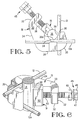
- the recesses 38,38a must span the point of contact 39 between the posts 14 and the conductors 12 where the post 14 has a cross-sectional configuration that would produce a single point of contact 39, such as is shown in Figure 5. If the post has a square cross section, a line of contact 39a is established and the recesses must span this line a sufficient distance to positively hold the post and conductor against each other.
- Signal reference grids most commonly involve conductors 12,12a that cross at 90 degree angles.
- a feature of the present invention is that the conductors 12,12a may be connected with the post 14 without having significant deviation from their natural orientation.
- the jaws 34,36 are orientated approximately square to each other corresponding to the paths of the conductors 12,12a in the grid, thereby enabling the conductors 12,12a to be interconnected with the post 14 without requiring substantial deviation from their natural path. By not altering the path of the conductors the amount of conductor material needed to form the grid and the installation time is minimized.
- a clamping mechanism 18 is employed to hold the post 14 against the conductors 12.
- the clamping mechanism 18 includes a clamp tightening screw 40 within a threaded bore 42 that passes through the inner 26 and outer 28 surfaces at the second end portion 22 of the body 16.
- the clamping mechanism 18 has an engaged position, shown in Figures 5-8, where the post 14 is being held tightly in the seat 23 and against the conductors 12.
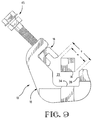
- the clamping mechanism 18 also has a disengaged position, as shown in Figure 9, where the clamping mechanism 18 is retracted towards the second end portion 22 of the body 16. In the disengaged position, the post 14 is side-accessible to the connector 10 enabling the connector 10 to be installed on the post 14 when the ends of the post 14 are no longer accessible.
- the clamping mechanism acts along a line 44 that bisects the angle defined between the two jaws 34,36. By acting along this line 44, the force exerted by the clamping mechanism 18 will tend to align the body 16, the post 14 and the conductors 12 as the clamping mechanism 18 is tightened to effect the most secure engagement of the connector 10 to the post 14 and therefore the post 14 against the conductor 12.
- the clamp tightening screw 40 can be adapted to limit the amount of compression the clamping mechanism 18 can produce, thereby protecting the post 14, conductors 12,12a and the connector 10 from damage due to over-tightening by incorporating a shear-head 45 into the clamp tightening screw 40.
- the shear-head 45 has a first head 46 and a second head 48 separated from each other by an undercut 50 extending into the screw 40. By adjusting the depth of the undercut 50 the amount of force exerted on the post 14 can be controlled.
- An undercut 50 is selected that allows the first head 46 to shear from the screw 40 when the amount of torque on the first head 46 exceeds the amount of torque required to produce the desired compressive force.
- the two heads 46,48 are aligned and a lip 47, where the first head 46 meets the undercut 50, prevents a wrench socket from also engaging the second head 48. This could also be accomplished by placing a C-clip in the undercut or by offsetting the heads 46,48 relative to each other.
- the second head 48 remains on the screw 40 for disassembly.
- the shear-head 45 provides a convenient way of assuring clamping does not damage the post while still exerting the necessary amount of force to establish the electrical connection. It also assures that the force necessary to deflect the body upon tightening, but not enough to exceed the elastic limits of the material, is exerted during clamping. This deflection stores energy within the body 16 which acts as a residual force to accommodate any relaxation of the conductor 12 or the clamping mechanism 18 in order to maintain the connector 10 in tight engagement with the conductor 12 and the connection.
- the connector 10 may be used with the second head 48 intact by using a torque wrench or an equivalent device.
- a clamp block 52 may be incorporated on the end of the clamping screw 40.
- the clamp block 52 acts to distribute the applied clamping load across the post 14, thereby protecting the post 14 from damage while still generating the necessary forces discussed above.
- the clamp block 52 is attached to the screw 40 in a manner that allows the rotation of the screw 40 without corresponding rotation of the clamp block 52. It is presently envisioned to create this interconnection by peening over a dog point 54 on the end of the screw 40 within a countersunk bore 56 in the block 52, whereby the deformation of the dog point 54 is sufficient to loosely captivate the block 52 on the screw 40.
- a V-shaped groove 60 may also be incorporated into a face 62 of the clamping block 52 to aid in distributing the clamping force over the post 14.
- the V-groove 60 may be a simple groove having straight sides with a 90 degree included angle or a compound groove 60 having a bottom section 62 with a 90 degree included angle for gripping the sides of a square post and a top section 64 having a 135 degree included angle for gripping round posts.
- This groove 60 engages the round post 14 in two locations and a square post 14 along two sides, as shown in Figures 5 and 7 respectfully.
- a relief cut 66 may be included in the bottom of the groove to prevent interference with the corner of a square post.
- the clamping mechanism 18 is moved to its disengaged position and the connector 10 is installed about the post 14.
- the connector 10 is capable of excepting posts having a cross-sectional width ⁇ that is less than the opening defined when the clamping mechanism 18 is in the disengaged position.
- the clamping mechanism 18 is then lightly tightened about the post 14 sufficient to hold the connector 10 in place on the post 14.
- the clamping mechanism 18 is then backed-off from the post 14 sufficient to allow the conductors 12 to be placed in the corresponding recesses 38 of the connector body 16.
- the connector 10 will be used with crossing conductors 12,12a.
- the first conductor 12 will be placed in the upper recess 38 of the jaw 34 that corresponds to the path of the conductor 12, while the second conductor 12a would be placed in the lower recess 38a of the other jaw 36.
- the connector will also be possible to use the connector with only one conductor or with parallel conductors without bending the conductor from its original path.
- the clamping mechanism 18 can be advanced to its engaged position tight against the post 14 which is now held firmly against the conductors 12,12a within the body 16 of the connector 10. If a shear head bolt is being used, the first head 46 is tightened, using a conventional wrench, until the first head 46 shears from the tightening screw 40. The installation of the connector 10 is complete.
Abstract
Description
- This invention relates to a device for connecting a ground conductor to a post.
- A raised sub-floor, constructed on posts or pedestals above the true floor of a structure, is a common design feature in computer room installations. This feature enables the cables and conduits of the electrical power distribution network and the assorted system interconnections to be located out of the way of the equipment operators. The raised sub-floor is becoming more common in conventional office space due to the automation of the modern office.
- A proper ground is essential for both the equipment and the power distribution network to insure proper operation of the electronic devices and protect the operators. The equipment grounds and the power distribution ground must be interconnected to assure that there is no difference in electrical potential between components. This interconnection typically occurs beneath the raised sub-floor.
- Safety regulations in the United States National Electrical Code (NEC) and the Canadian Electrical Code (CEC) require that all non-current carrying metal parts in these installations be grounded. It is convenient to establish a signal reference grid of crossing conductors beneath the raised sub-floor that incorporates the posts of the raised sub-floor to establish multiple conducting paths to ground. The grid assures that there is no voltage difference across the floor and that the floor has an impedance to ground that does not inhibit the flow of fault current. The low impedance to ground enables the grid to attenuate high-frequency noise which might effect electronic data transmission, ground the power distribution system to minimize the effects of noise from the power distribution system on the Automatic Data Processing (ADP) equipment and ground the capacitance charge, such as static electricity, present in the environment of the installation.
- Because conductors of the signal reference grid typically cross at locations corresponding to the posts of the raised sub-floor, it would be helpful to have a single connector that is capable of fastening a plurality of conductors to a post without requiring the path of the conductor to be substantially altered. In addition, the connector should be: inexpensive; simple to install; usable over a range of conductor sizes and compatible with a range of post sizes and shapes.
- A tap clamp, as disclosed in United States Pat No. 2,155,524, which issued March 21, 1939 to Pittman et al., includes a frame having a V-shaped nest or seat for receiving an electrical conductor to which a tap wire is to be attached. The tap wire is threaded through a pair of orthogonally positioned holes that direct the wire along both inside surfaces of the V-shaped nest. The conductor is positioned within the V-shaped nest against the two legs of the tap wire and a screw jack is tightened against the conductor forcing it into electrical engagement with the two legs of the tap wire. However, such a tap clamp is not suitable for electrically connecting a pair of crossing grit conductors to a floor support post.
- It is an object of this invention to provide a connector for connecting a conductor to a post and in particular a conductor of a signal reference grid to a crossing post. It is another object of this invention to provide a connector that does not require the conductor to substantially deviate from its natural path within the grid in order to be connected to the post. It is yet another object of this invention to provide a connector that can maintain a tight connection between the conductor and the post over time.
- It is a feature of this invention to have a body with a first end portion with an inner surface that defines a seat, for receiving the post, which includes a plurality of recesses formed in the inner surface along the seat that are adapted to selectively receive the conductor and position the conductor so that the post may be pressed tightly thereagainst by a clamping mechanism to establish the electrical connection. It is a feature of an embodiment of the invention that the inner surface of the seat includes a base jaw and a back-up jaw having the recesses therealong and defining an angle therebetween that corresponds to the angle formed by crossing conductors. It is a feature of an embodiment of the invention that the clamping mechanism may act along a line that bisects the angle between the two jaws to aid in aligning and securing the mating components as the post is pressed into the seat and against the conductor.
- It is an advantage of this invention that it may be used with a variety of different post sizes and a variety of different post cross-sectional configurations. It is another advantage of this invention that it is usable with a range of different conductor sizes.
- According to the present invention, a ground connector is provided for connecting a conductor to a post that crosses the path of the conductor. A specific application being the interconnection of a conductor of a signal reference grid to a post or pedestal used to support a sub-floor of a computer room or office installation. The ground connector for connecting a conductor to a post, is characterized by:
a body having a first end portion and a second end portion joined by a middle portion, the first end portion having an inner surface defining a seat profiled for receiving the post, and a plurality of recesses along the inner surface of the seat for selectively seating the conductor so that when the post is within the seat the post may be held in tight engagement thereagainst; and
a clamping mechanism movable between an engaged position where the post is held tightly in the seat and against the conductor and a disengaged position where the connector may be removed from the post. Preferred embodiments thereof are defined in the dependent claims. - The invention will now be described by way of example with reference to the accompanying drawings in which;
- Figure 1 is a perspective view of the connector.
- Figure 2 is a rear side view of the connector.
- Figure 3 is a cut-away view of the connector along line 3-3 of Figure 2.
- Figure 4 is top view of the connector.
- Figure 5 is a top view of the connector showing crossing conductors connected to a round post.
- Figure 6 is a perspective view of the connector showing crossing conductors connected to a round post.
- Figure 7 is a top view of the connector showing crossing conductors connected to a square post.
- Figure 8 is a perspective view of the connector showing crossing conductors connected to a square post.
- Figure 9 is a top view of the connector in the disengaged position with a square post.
- The drawings show a signal
reference grid connector 10 for connecting aconductor 12 to apost 14. Thepost 14 may be a pedestal or support post of a raised sub-floor installation (not shown), in which case thepost 14 will be orientated vertically, and theconductor 12 may be part of a signal reference grid (not shown) installed horizontally beneath the raised sub-floor. It is possible to use theconnector 10 with apost 14 having a round cross-section, as shown in Figures 6 and 7, or a polygonal cross-section as illustrated by, but not limited to a square cross-section shown in Figures 7 and 8. - The
connector 10 comprises abody 16 and aclamping mechanism 18. Thebody 16 includes afirst end portion 20 and asecond end portion 22 joined by amiddle portion 24, whereby a generally C-shaped member is formed. The proportions of thebody 16 are selected so that whenconnector 10 is installed on apost 14, the body acts as a spring and elastically deflects storing a residual force to cope with any relaxation of theconductors 12 or theconnector 10. Extending along these portions 20-24 are aninner surface 26, anouter surface 28 and upper andlower side surfaces - It is presently envisioned that the body will be cast of an aluminum alloy and have smooth blend radii throughout. The drawings do not include these radii to better illustrate the
body 16. It would be possible to manufacture the connector body from other conductive materials and to use other manufacturing methods, such as machining or forging. It is also envisioned that a plating, such as tin, may be deposited on theconnector 10 to enhance corrosion resistance. Because the post is conductive, it is not necessary that theconnector body 16 also be made from a conductive material. A conductive path between thecrossing conductors post 14 rather than through theconnector body 16. Therefore, theconnector body 16 may be made from a plastic or another dielectric compound. - The
first end portion 20 is profiled to receive thepost 14 within aseat 23 defined by theinner surface 26. Theseat 23 includes abase jaw 34 and a back-up jaw 36. Thesejaws polygonal posts 14 as discussed above. - The range of sizes of
posts 14 that theconnector 10 can accept is dependent on the size of theseat 23, which is dependent on the size of thejaws connector 10 is capable of accommodating square posts ranging in size from 3/4 inches to 7/8 inches and 1 inch round posts. - Incorporated into each of the
jaws recesses upper side surface 30 and thelower side surface 32, respectively. Theserecesses 38 are partial cylindrical indentations. The depth and the size of therecess 38 determines the size of theconductor 12 that theconnector 10 can accommodate. The depth of therecesses 38 must be sufficiently shallow to expose enough of theconductor 12 above theinner surface 26 along the jaw so that thepost 14 can be tightly pressed thereagainst. Signal reference grids may be formed with No. 4 AWG (American Wire Gage) to No. 8 AWG wire. It would also be possible to havedeeper recesses 38 and incorporate projections that extend from the surface of thepost 14 to engage theconductor 12. - In addition to the depth of the
recess 38 being a controlling factor as to the range ofconductor 12 sizes theconnector 10 may accommodate, the distance that the recess extends along thejaw post 14 sizes and post configurations that theconnector 10 can accept. Therecesses contact 39 between theposts 14 and theconductors 12 where thepost 14 has a cross-sectional configuration that would produce a single point ofcontact 39, such as is shown in Figure 5. If the post has a square cross section, a line ofcontact 39a is established and the recesses must span this line a sufficient distance to positively hold the post and conductor against each other. - Signal reference grids most commonly involve
conductors conductors post 14 without having significant deviation from their natural orientation. As shown in the drawings, thejaws conductors conductors post 14 without requiring substantial deviation from their natural path. By not altering the path of the conductors the amount of conductor material needed to form the grid and the installation time is minimized. It is possible to apply this invention to grids where theconductors connector 10 that has the angular relationship between thejaws recesses grid conductors - A
clamping mechanism 18 is employed to hold thepost 14 against theconductors 12. Theclamping mechanism 18 includes aclamp tightening screw 40 within a threadedbore 42 that passes through the inner 26 and outer 28 surfaces at thesecond end portion 22 of thebody 16. Theclamping mechanism 18 has an engaged position, shown in Figures 5-8, where thepost 14 is being held tightly in theseat 23 and against theconductors 12. Theclamping mechanism 18 also has a disengaged position, as shown in Figure 9, where theclamping mechanism 18 is retracted towards thesecond end portion 22 of thebody 16. In the disengaged position, thepost 14 is side-accessible to theconnector 10 enabling theconnector 10 to be installed on thepost 14 when the ends of thepost 14 are no longer accessible. - Ideally, the clamping mechanism acts along a
line 44 that bisects the angle defined between the twojaws line 44, the force exerted by theclamping mechanism 18 will tend to align thebody 16, thepost 14 and theconductors 12 as theclamping mechanism 18 is tightened to effect the most secure engagement of theconnector 10 to thepost 14 and therefore thepost 14 against theconductor 12. - The
clamp tightening screw 40 can be adapted to limit the amount of compression theclamping mechanism 18 can produce, thereby protecting thepost 14,conductors connector 10 from damage due to over-tightening by incorporating a shear-head 45 into theclamp tightening screw 40. The shear-head 45 has afirst head 46 and asecond head 48 separated from each other by an undercut 50 extending into thescrew 40. By adjusting the depth of the undercut 50 the amount of force exerted on thepost 14 can be controlled. An undercut 50 is selected that allows thefirst head 46 to shear from thescrew 40 when the amount of torque on thefirst head 46 exceeds the amount of torque required to produce the desired compressive force. The two heads 46,48 are aligned and alip 47, where thefirst head 46 meets the undercut 50, prevents a wrench socket from also engaging thesecond head 48. This could also be accomplished by placing a C-clip in the undercut or by offsetting theheads second head 48 remains on thescrew 40 for disassembly. - The shear-
head 45 provides a convenient way of assuring clamping does not damage the post while still exerting the necessary amount of force to establish the electrical connection. It also assures that the force necessary to deflect the body upon tightening, but not enough to exceed the elastic limits of the material, is exerted during clamping. This deflection stores energy within thebody 16 which acts as a residual force to accommodate any relaxation of theconductor 12 or theclamping mechanism 18 in order to maintain theconnector 10 in tight engagement with theconductor 12 and the connection. Theconnector 10 may be used with thesecond head 48 intact by using a torque wrench or an equivalent device. - In order to increase clamping effectiveness a
clamp block 52 may be incorporated on the end of the clampingscrew 40. Theclamp block 52 acts to distribute the applied clamping load across thepost 14, thereby protecting thepost 14 from damage while still generating the necessary forces discussed above. Theclamp block 52 is attached to thescrew 40 in a manner that allows the rotation of thescrew 40 without corresponding rotation of theclamp block 52. It is presently envisioned to create this interconnection by peening over adog point 54 on the end of thescrew 40 within a countersunkbore 56 in theblock 52, whereby the deformation of thedog point 54 is sufficient to loosely captivate theblock 52 on thescrew 40. - A V-shaped
groove 60 may also be incorporated into aface 62 of the clampingblock 52 to aid in distributing the clamping force over thepost 14. For example, the V-groove 60 may be a simple groove having straight sides with a 90 degree included angle or acompound groove 60 having abottom section 62 with a 90 degree included angle for gripping the sides of a square post and atop section 64 having a 135 degree included angle for gripping round posts. Thisgroove 60 engages theround post 14 in two locations and asquare post 14 along two sides, as shown in Figures 5 and 7 respectfully. A relief cut 66 may be included in the bottom of the groove to prevent interference with the corner of a square post. - In order to use the present invention, the
clamping mechanism 18 is moved to its disengaged position and theconnector 10 is installed about thepost 14. As shown in Figure 9, theconnector 10 is capable of excepting posts having a cross-sectional width α that is less than the opening defined when theclamping mechanism 18 is in the disengaged position. Theclamping mechanism 18 is then lightly tightened about thepost 14 sufficient to hold theconnector 10 in place on thepost 14. Theclamping mechanism 18 is then backed-off from thepost 14 sufficient to allow theconductors 12 to be placed in the correspondingrecesses 38 of theconnector body 16. - Typically, the
connector 10 will be used with crossingconductors conductors first conductor 12 will be placed in theupper recess 38 of thejaw 34 that corresponds to the path of theconductor 12, while thesecond conductor 12a would be placed in thelower recess 38a of theother jaw 36. It will also be possible to use the connector with only one conductor or with parallel conductors without bending the conductor from its original path. When using the connector with a single conductor it may be desirable to use a "dummy" piece of wire or short length of rod within another recess to stabilize the connector by simulating a second conductor. - Once the
conductors recesses clamping mechanism 18 can be advanced to its engaged position tight against thepost 14 which is now held firmly against theconductors body 16 of theconnector 10. If a shear head bolt is being used, thefirst head 46 is tightened, using a conventional wrench, until thefirst head 46 shears from the tighteningscrew 40. The installation of theconnector 10 is complete. - It will be appreciated that the present invention has significant advantages for connecting conductors of a signal reference grid to a sub-floor support post. It should be recognized that the above-described embodiment constitutes the presently preferred form of the invention and that the invention can take numerous other forms, some of which have been described above, and may be used in other types of applications. Accordingly, the invention should be limited only as required by the scope of the following claims.
Claims (10)
- A ground connector (10) for connecting a conductor (12) to a post (14), characterized by:
a body (16) having a first end portion (20) and a second end portion (22) joined by a middle portion (24), the first end portion (20) having an inner surface (26) defining a seat (23) profiled for receiving the post (14), and a plurality of recesses (38,38a) along the inner surface (26) of the seat (23) for selectively seating the conductor (12) so that when the post (14) is within the seat the post may be held in tight engagement thereagainst; and
a clamping mechanism (18) movable between an engaged position where the post (14) is held tightly in the seat (23) and against the conductor (12) and a disengaged position where the connector (12) may be removed from the post (14). - A ground connector (10) for connecting crossing conductors (12,12a) to a post (14), characterized by:
a body (16) having a first end portion (20) and a second end portion (22) joined by a middle portion (24), the first end portion (20) having an inner surface (26) including a seat (23) for receiving the post (14), and a plurality of recesses (38,38a) along the seat (23) for selectively seating the conductors (12,12a) so that the seated post (14) may be held in tight engagement thereagainst; and
a clamping mechanism (18) movable between an engaged position where the post (14) is held tightly in the seat (23) and against the conductors (12,12a) and a disengaged position where the connector (10) may be removed form the post (14). - The ground connector (10) of Claims 1 or 2, characterized in that the inner surface (26) of the seat has a base jaw (34) and a back-up jaw (36) that define an angle therebetween.
- The ground connector (10) of Claim 3, characterized in that the clamping mechanism (18) moves along a line that bi-sects the angle between the base jaw (34) and the back-up jaw (36).
- The ground connector (10) of any of claims 1 to 4, characterized in that the clamping mechanism (18) is a clamp tightening screw (40) in communication with a threaded bore (42) at the second end portion (22) of the body (16).
- The ground connector (10) of Claim 5, characterized in that the clamp tightening screw (40) has a shear-head (45) to provide controlled torque installation.
- The ground connector (10) of Claim 6, characterized in that the shear-head (45) comprises a first head (46) and a second head (48) separated by an undercut (50) extending into the screw (46) for limiting the amount of force that can be exerted by the clamp tightening screw (40) by tightening the first head (46).
- The ground connector (10) of any of claims 1 to 7, characterized in that the clamping mechanism (18) includes a clamp block (52) having a face (62) adapted to engage the post (14).
- The ground connector (10) of Claim 8, characterized in that the face (62) has a V-shaped groove (60) therein extending along the face (62) along the post (14).
- The ground connector (10) of Claim 9, characterized in that the V-shaped groove (60) has opposing compound surfaces (62,64) defining an included angle closest to the bottom of the groove (60) of 90 degrees and an included angle closest to the top of the groove (60) of 135 degrees.
Applications Claiming Priority (2)
| Application Number | Priority Date | Filing Date | Title |
|---|---|---|---|
| US11021 | 1993-01-29 | ||
| US08/011,021 US5286211A (en) | 1993-01-29 | 1993-01-29 | Ground connector |
Publications (2)
| Publication Number | Publication Date |
|---|---|
| EP0608877A2 true EP0608877A2 (en) | 1994-08-03 |
| EP0608877A3 EP0608877A3 (en) | 1995-11-22 |
Family
ID=21748516
Family Applications (1)
| Application Number | Title | Priority Date | Filing Date |
|---|---|---|---|
| EP94101194A Ceased EP0608877A3 (en) | 1993-01-29 | 1994-01-27 | Ground connector. |
Country Status (8)
| Country | Link |
|---|---|
| US (1) | US5286211A (en) |
| EP (1) | EP0608877A3 (en) |
| JP (1) | JPH06243912A (en) |
| KR (1) | KR940019023A (en) |
| CN (1) | CN1094194A (en) |
| AU (1) | AU673863B2 (en) |
| BR (1) | BR9400312A (en) |
| CA (1) | CA2111608A1 (en) |
Cited By (1)
| Publication number | Priority date | Publication date | Assignee | Title |
|---|---|---|---|---|
| US9187654B2 (en) | 2009-05-06 | 2015-11-17 | Carrie A. Feeney | Barrier coatings post-formation treated with multi-valent metal cations |
Families Citing this family (40)
| Publication number | Priority date | Publication date | Assignee | Title |
|---|---|---|---|---|
| US5553963A (en) * | 1994-12-08 | 1996-09-10 | Hoy; Thomas A. | Clamp device for a ladder adjustment apparatus |
| USD388052S (en) * | 1995-05-19 | 1997-12-23 | Teracom Components Ab | Grounding component for electric cables |
| DE19601457C1 (en) * | 1996-01-17 | 1997-02-06 | Loh Kg Rittal Werk | Connector |
| US5829992A (en) * | 1996-03-08 | 1998-11-03 | Merker; Joseph J. | Device and method for grounding /bonding cable television connectors |
| US5928007A (en) * | 1996-05-17 | 1999-07-27 | Teracom Components Ab | Device for grounding feed cables between transmitters or receivers and antennas |
| US5933924A (en) * | 1997-05-09 | 1999-08-10 | Nowlen; William M. | Power line insulator clamp |
| ATE322753T1 (en) * | 2001-12-22 | 2006-04-15 | Richard Bergner Elektroarmatur | FIXING CLAMP FOR AN AIR CABLE |
| US6722643B1 (en) * | 2002-05-23 | 2004-04-20 | William C. Kurtz | Multi-clamp |
| US20040181912A1 (en) * | 2003-01-30 | 2004-09-23 | Ilya Feygin | Article comprising an ergonomic handle |
| US6986673B2 (en) * | 2004-04-09 | 2006-01-17 | Thomas & Betts International, Inc. | Grounding clamp for raised floor |
| US20060094270A1 (en) * | 2004-11-03 | 2006-05-04 | Mark Engler | Positioning device for securing earth line of a signal transferring unit |
| US7160142B2 (en) * | 2005-01-04 | 2007-01-09 | Cooper Technologies Company | Grounding clamp apparatus and method |
| US20080116332A1 (en) * | 2006-11-21 | 2008-05-22 | Van Der Meulen Jan Roelof | Leg system for drums |
| US8303757B2 (en) | 2006-12-04 | 2012-11-06 | The Boeing Company | Tensioning device for composite structures |
| US7670153B2 (en) * | 2007-09-10 | 2010-03-02 | Burndy Technology Llc | Electrical connector |
| US7988464B2 (en) * | 2008-04-09 | 2011-08-02 | Panduit Corp. | Beam clamp |
| US7803001B2 (en) * | 2008-12-10 | 2010-09-28 | Burndy Technology, LLC | Ground connector |
| US8938918B2 (en) * | 2008-12-22 | 2015-01-27 | Hubbell Incorporated | Raised floor system grounding |
| US8007293B2 (en) * | 2008-12-29 | 2011-08-30 | Hubbell Incorporated | Grounding rebar connector |
| US7794243B1 (en) * | 2009-02-27 | 2010-09-14 | Burndy Technology, LLC | Ground connector |
| US8038453B2 (en) * | 2009-02-27 | 2011-10-18 | Hubbell Incorporated | Ground connector |
| US8313334B2 (en) * | 2009-09-11 | 2012-11-20 | Hubbell Incorporated | Pedestal ground connector |
| US8688237B2 (en) | 2009-10-02 | 2014-04-01 | Medtronic Xomed, Inc. | Endotracheal tube apparatus |
| US7922546B1 (en) | 2009-12-02 | 2011-04-12 | Thomas & Betts Intenational, Inc. | Grounding clamp |
| CN102161143A (en) * | 2011-04-01 | 2011-08-24 | 上海电气核电设备有限公司 | Auxiliary fixture for assembling shock-resistant strip used for steam generator pipe bundle |
| US9931079B2 (en) * | 2012-01-04 | 2018-04-03 | Medtronic Xomed, Inc. | Clamp for securing a terminal end of a wire to a surface electrode |
| US8864502B2 (en) | 2012-05-04 | 2014-10-21 | Thomas & Betts International, Inc. | Mechanical grounding connector |
| US9060744B2 (en) | 2012-11-29 | 2015-06-23 | Medtronic Xomed, Inc. | Endobronchial tube apparatus |
| US9913594B2 (en) | 2013-03-14 | 2018-03-13 | Medtronic Xomed, Inc. | Compliant electrode for EMG endotracheal tube |
| US9106067B1 (en) | 2013-09-09 | 2015-08-11 | Mike Vernica | Ground bushing with three way lay and lag |
| USD764249S1 (en) * | 2014-10-16 | 2016-08-23 | Acrefine Engineering Services, Ltd. | Rod stiffener clamp |
| US9787004B2 (en) | 2015-05-20 | 2017-10-10 | Thomas & Betts International Llc | Floor ground clamp |
| US11110240B2 (en) | 2017-09-07 | 2021-09-07 | Medtronic Xomed, Inc. | Endotracheal tube with tube coating |
| US10494867B1 (en) * | 2018-10-17 | 2019-12-03 | Marc Fort | Simply safe ladder clamp |
| US10920911B2 (en) | 2018-12-26 | 2021-02-16 | Commscope Technologies Llc | Adapter for mounting cable hangers |
| US10910805B2 (en) * | 2018-12-26 | 2021-02-02 | Commscope Technologies Llc | Adapter for mounting cable hangers |
| USD920852S1 (en) * | 2019-05-06 | 2021-06-01 | Cake 0 emission AB | Electric motorcycle |
| US20210281035A1 (en) * | 2020-03-09 | 2021-09-09 | Burndy, LLC | Conductor interface grabbing tool |
| JP7395418B2 (en) * | 2020-04-21 | 2023-12-11 | 株式会社サンテック | Grounding fitting |
| US11870166B2 (en) | 2020-08-19 | 2024-01-09 | Hubbell Incorporated | Low resistivity tap clamp |
Citations (6)
| Publication number | Priority date | Publication date | Assignee | Title |
|---|---|---|---|---|
| DE623406C (en) * | 1933-07-29 | 1935-12-19 | Kabelwerk Duisburg | CROSS TERMINAL FOR CREATING CROSS CONNECTIONS ON CONTINUOUS ELECTRICAL CABLES |
| US2151524A (en) * | 1938-06-10 | 1939-03-21 | Ralph R Pittman | Tap clamp |
| DE971877C (en) * | 1952-04-19 | 1959-04-09 | Hoppmann & Mulsow | Jaw clamp for connecting electrical lines |
| US3561317A (en) * | 1969-04-04 | 1971-02-09 | Anaconda American Brass Co | Self-indicating clamping bolt |
| US4189198A (en) * | 1978-07-31 | 1980-02-19 | Gould Inc. | Conduit ground wire coupling |
| US4911572A (en) * | 1988-06-13 | 1990-03-27 | Houston Industries Incorporated | Cable tie back clamp |
Family Cites Families (6)
| Publication number | Priority date | Publication date | Assignee | Title |
|---|---|---|---|---|
| US3622946A (en) * | 1970-03-02 | 1971-11-23 | Permali Inc | Electrical connector with breakaway stud |
| US3892455A (en) * | 1974-03-26 | 1975-07-01 | Thomas & Betts Corp | Ground clamp connector |
| US4105272A (en) * | 1977-07-11 | 1978-08-08 | A. B. Chance Company | High current grounding assembly having rigid interconnecting conductors |
| GB1582664A (en) * | 1978-05-24 | 1981-01-14 | Pentabloc Ltd | Joining member for frame systems |
| FR2566191B1 (en) * | 1984-06-15 | 1986-11-14 | Sicame Sa | INSULATED BYPASS CONNECTOR FOR ELECTRICAL CABLES |
| CA1286012C (en) * | 1988-09-09 | 1991-07-09 | Robin Paul Cera | Electrical grounding connector |
-
1993
- 1993-01-29 US US08/011,021 patent/US5286211A/en not_active Expired - Lifetime
- 1993-12-16 CA CA002111608A patent/CA2111608A1/en not_active Abandoned
- 1993-12-20 AU AU52590/93A patent/AU673863B2/en not_active Ceased
-
1994
- 1994-01-24 BR BR9400312A patent/BR9400312A/en not_active IP Right Cessation
- 1994-01-27 EP EP94101194A patent/EP0608877A3/en not_active Ceased
- 1994-01-27 KR KR1019940001412A patent/KR940019023A/en not_active Application Discontinuation
- 1994-01-28 CN CN94101138A patent/CN1094194A/en active Pending
- 1994-01-28 JP JP6008478A patent/JPH06243912A/en not_active Withdrawn
Patent Citations (6)
| Publication number | Priority date | Publication date | Assignee | Title |
|---|---|---|---|---|
| DE623406C (en) * | 1933-07-29 | 1935-12-19 | Kabelwerk Duisburg | CROSS TERMINAL FOR CREATING CROSS CONNECTIONS ON CONTINUOUS ELECTRICAL CABLES |
| US2151524A (en) * | 1938-06-10 | 1939-03-21 | Ralph R Pittman | Tap clamp |
| DE971877C (en) * | 1952-04-19 | 1959-04-09 | Hoppmann & Mulsow | Jaw clamp for connecting electrical lines |
| US3561317A (en) * | 1969-04-04 | 1971-02-09 | Anaconda American Brass Co | Self-indicating clamping bolt |
| US4189198A (en) * | 1978-07-31 | 1980-02-19 | Gould Inc. | Conduit ground wire coupling |
| US4911572A (en) * | 1988-06-13 | 1990-03-27 | Houston Industries Incorporated | Cable tie back clamp |
Cited By (1)
| Publication number | Priority date | Publication date | Assignee | Title |
|---|---|---|---|---|
| US9187654B2 (en) | 2009-05-06 | 2015-11-17 | Carrie A. Feeney | Barrier coatings post-formation treated with multi-valent metal cations |
Also Published As
| Publication number | Publication date |
|---|---|
| AU5259093A (en) | 1994-08-04 |
| CA2111608A1 (en) | 1994-07-30 |
| BR9400312A (en) | 1994-08-16 |
| KR940019023A (en) | 1994-08-19 |
| AU673863B2 (en) | 1996-11-28 |
| CN1094194A (en) | 1994-10-26 |
| US5286211A (en) | 1994-02-15 |
| JPH06243912A (en) | 1994-09-02 |
| EP0608877A3 (en) | 1995-11-22 |
Similar Documents
| Publication | Publication Date | Title |
|---|---|---|
| US5286211A (en) | Ground connector | |
| US5423699A (en) | Electrical connector | |
| US5011427A (en) | Cord protector | |
| CA1234196A (en) | Electric tap connector | |
| EP0162373B1 (en) | Electrical installation consisting of assembled single modules | |
| CA2068692C (en) | Electrical wire connector | |
| CA1286012C (en) | Electrical grounding connector | |
| EP0237141A2 (en) | Cable terminal connector with insulation displacing terminals | |
| JPH07263044A (en) | Electric connector | |
| GB2173650A (en) | Cable terminal connector with insulation displacing terminals | |
| US5876224A (en) | Bus bar adaptor | |
| US5593327A (en) | Cable connector | |
| EP0813755B1 (en) | Improved electrical wire connector | |
| US4840581A (en) | Cable jacket strain relief adapter assembly | |
| US4527849A (en) | Snap-in mounting device for electrical devices | |
| US6045379A (en) | Device connecting conductors or devices to a bus bar in a bus bar system | |
| IE861538L (en) | Earthing system | |
| US5281173A (en) | Electrical distribution system connector | |
| CA1236191A (en) | Coaxial cable clamp | |
| CN1037730C (en) | Electrical connector | |
| US5679032A (en) | Strain relief device for clamp assembly | |
| US5401194A (en) | Cable clamp with reduced fastener length | |
| DE4306868C1 (en) | Connecting terminal for low-voltage cables | |
| US4925332A (en) | Single-plane T-connector for a pair of tap cables | |
| US20020090847A1 (en) | Ground connector |
Legal Events
| Date | Code | Title | Description |
|---|---|---|---|
| PUAI | Public reference made under article 153(3) epc to a published international application that has entered the european phase |
Free format text: ORIGINAL CODE: 0009012 |
|
| AK | Designated contracting states |
Kind code of ref document: A2 Designated state(s): DE FR GB IT NL |
|
| PUAL | Search report despatched |
Free format text: ORIGINAL CODE: 0009013 |
|
| AK | Designated contracting states |
Kind code of ref document: A3 Designated state(s): DE FR GB IT NL |
|
| 17P | Request for examination filed |
Effective date: 19960509 |
|
| 17Q | First examination report despatched |
Effective date: 19970604 |
|
| GRAG | Despatch of communication of intention to grant |
Free format text: ORIGINAL CODE: EPIDOS AGRA |
|
| STAA | Information on the status of an ep patent application or granted ep patent |
Free format text: STATUS: THE APPLICATION HAS BEEN REFUSED |
|
| 18R | Application refused |
Effective date: 19990725 |