EP0608681B1 - Oscillator circuit with a memory for memorising characteristic information individual to the quartz vibrator - Google Patents
Oscillator circuit with a memory for memorising characteristic information individual to the quartz vibrator Download PDFInfo
- Publication number
- EP0608681B1 EP0608681B1 EP94100070A EP94100070A EP0608681B1 EP 0608681 B1 EP0608681 B1 EP 0608681B1 EP 94100070 A EP94100070 A EP 94100070A EP 94100070 A EP94100070 A EP 94100070A EP 0608681 B1 EP0608681 B1 EP 0608681B1
- Authority
- EP
- European Patent Office
- Prior art keywords
- oscillator circuit
- clock
- characteristic information
- quartz crystal
- oscillator
- Prior art date
- Legal status (The legal status is an assumption and is not a legal conclusion. Google has not performed a legal analysis and makes no representation as to the accuracy of the status listed.)
- Expired - Lifetime
Links
- 239000010453 quartz Substances 0.000 title claims description 48
- VYPSYNLAJGMNEJ-UHFFFAOYSA-N silicon dioxide Inorganic materials O=[Si]=O VYPSYNLAJGMNEJ-UHFFFAOYSA-N 0.000 title claims description 48
- 239000013078 crystal Substances 0.000 claims abstract description 50
- 238000005259 measurement Methods 0.000 claims description 33
- 238000000034 method Methods 0.000 claims description 3
- 238000009529 body temperature measurement Methods 0.000 claims 1
- 238000001514 detection method Methods 0.000 claims 1
- 235000012239 silicon dioxide Nutrition 0.000 description 33
- 238000012545 processing Methods 0.000 description 20
- 238000011156 evaluation Methods 0.000 description 10
- 230000006870 function Effects 0.000 description 4
- 238000004519 manufacturing process Methods 0.000 description 3
- 230000032683 aging Effects 0.000 description 2
- 238000004891 communication Methods 0.000 description 2
- 238000010586 diagram Methods 0.000 description 2
- 230000033764 rhythmic process Effects 0.000 description 2
- 230000001419 dependent effect Effects 0.000 description 1
- 238000005516 engineering process Methods 0.000 description 1
- 238000002847 impedance measurement Methods 0.000 description 1
- 230000010365 information processing Effects 0.000 description 1
- 230000010355 oscillation Effects 0.000 description 1
- 230000001105 regulatory effect Effects 0.000 description 1
Images

Classifications
-
- H—ELECTRICITY
- H03—ELECTRONIC CIRCUITRY
- H03L—AUTOMATIC CONTROL, STARTING, SYNCHRONISATION OR STABILISATION OF GENERATORS OF ELECTRONIC OSCILLATIONS OR PULSES
- H03L1/00—Stabilisation of generator output against variations of physical values, e.g. power supply
- H03L1/02—Stabilisation of generator output against variations of physical values, e.g. power supply against variations of temperature only
- H03L1/022—Stabilisation of generator output against variations of physical values, e.g. power supply against variations of temperature only by indirect stabilisation, i.e. by generating an electrical correction signal which is a function of the temperature
- H03L1/026—Stabilisation of generator output against variations of physical values, e.g. power supply against variations of temperature only by indirect stabilisation, i.e. by generating an electrical correction signal which is a function of the temperature by using a memory for digitally storing correction values
-
- H—ELECTRICITY
- H03—ELECTRONIC CIRCUITRY
- H03L—AUTOMATIC CONTROL, STARTING, SYNCHRONISATION OR STABILISATION OF GENERATORS OF ELECTRONIC OSCILLATIONS OR PULSES
- H03L1/00—Stabilisation of generator output against variations of physical values, e.g. power supply
- H03L1/02—Stabilisation of generator output against variations of physical values, e.g. power supply against variations of temperature only
- H03L1/028—Stabilisation of generator output against variations of physical values, e.g. power supply against variations of temperature only of generators comprising piezoelectric resonators
Definitions
- oscillator circuits are predominantly implemented with quartz crystals due to increased stability and safety requirements.
- the quartz crystals have different temperature-dependent resonance frequencies depending on the quartz cuts.
- the temperature dependency is defined by a temperature characteristic curve or characteristic information that is specific to oscillating quartz and is determined or measured during quartz production.
- This temperature-related and other individual quartz crystal-specific information eg changes in the quartz crystal properties due to the aging of the quartz crystal - are communicated to the users of quartz crystals - especially in oscillator circuits - on data sheets or for each quartz separately in printed form.
- imprints on the quartz crystals are known, by means of which the quartz-individual-specific identification information can be extracted from data sheets.
- the quartz crystals are preferably used in oscillator circuits in which digital clock signals are formed with a frequency predetermined by the quartz crystal. Due to the individual properties of the quartz crystals, the quartz-individual-specific information must be available in the clock devices processing the digital clock signals and connected to the oscillator circuit - in particular in phase-locked loop-controlled clock devices - for highly precise clock controls. Since clock control methods implemented by programs are increasingly provided in the clock devices, the quartz-individual-specific characteristic information of the assigned oscillator circuit is entered for each clock control separately. This means a considerable additional effort when assigning an oscillator circuit to a clock device or to a device in which high-precision processing of the clock signals takes place and in which the characteristic quartz oscillation-specific information must consequently be introduced.
- the invention is therefore based on the object of reducing this considerable outlay for introducing the quartz-individual-specific characteristic information into the further processing device connected to the respective oscillator circuit.
- the object is achieved on the basis of an oscillator circuit according to the preamble of claim 1 by its characterizing features.
- the essential aspect of the oscillator circuit according to the invention can be seen in the fact that a means storing the quartz-crystal-specific information is arranged and configured in such a way that the quartz-crystal-specific information is controlled as analog, digital, coded digital signals or modulated signals at an output of the oscillator circuit.
- the individual quartz crystal information is preferably stored when the oscillator circuit is manufactured.
- the main advantage of the oscillator circuit according to the invention can be seen in the fact that after the oscillating-crystal-specific identification information has been stored once, this identification information is continuously available to the further processing devices at an output of the oscillator circuit and thus no longer has to be introduced by complex storing when connecting or changing a further processing device .
- the means storing the quartz-individual-specific characteristic information is particularly advantageous realized by a means for influencing the clock signals - claim 2.
- the quartz-individual identification information together with the clock signals are routed to the already existing output for the clock signals, the clock signals being influenced as a function of the stored quartz-individual identification information.
- This possibility of influencing is also possible for clock signals which are formed in a measuring oscillator arranged in the oscillator circuit - claim 3.
- the current temperature of the oscillator circuit is measured and the measuring signals formed - preferably digital measuring signals - are via a measuring output of the Oscillator circuit led to further processing facilities.
- the essential properties of a temperature oscillator circuit can be seen in the fact that temperature changes cause the highest possible frequency changes in the measurement signals formed.
- the characteristic temperature curve of a quartz crystal represents essential quartz-individual characteristic information, the temperature characteristic curves indicating the resonance frequencies of the respective quartz crystal as a function of the ambient temperature.
- a group of temperature characteristic curves is assigned to a quartz-individual characteristic information.
- the size of the assigned group of temperature characteristic curves is to be matched to the required accuracy of the frequency stability of the clock signals formed. This means that with increasing accuracy requirements, the number of temperature characteristics per group has to be reduced.
- a particularly advantageous variant is the pulse duration or pulse pause modulation of the clock signals or the measurement signals, since by combining a plurality of clock signals or measurement signals, coded, arbitrarily extensive information is formed and can be transmitted to a further processing device.
- the influencing of the clock signals or measurement signals is implemented by known modulation devices, frequency setting devices, level devices and impedance devices.
- the means for storing the quartz-individual characteristic information or temperature characteristic information are advantageously implemented by adjustable setting means which form digital information or programmable storage means - claim 7.
- the setting means are formed, for example, by switching elements or coding switching elements which are used in the manufacture of an oscillator circuit, ie during production of a clock oscillator generating clock signals, can be set in accordance with the currently measured temperature characteristic of the oscillating crystal.
- the temperature characteristic curve information can be stored once in a programmable memory of the oscillator circuit arranged in the oscillator circuit be saved. This storage can only be changed when the quartz crystal in the respective oscillator circuit changes.
- a means for recognizing and evaluating the modified or influenced clock or measurement signals is arranged in a further processing device connected to the output or the measurement output of the oscillator circuit, and is designed in such a way that that the individual quartz crystal information can be derived from the supplied modified or influenced clock or measurement signal - claim 8.
- Analogous to the means for influencing the clock signals or measurement signals in the further processing devices are the means for recognizing and evaluating the modified clock signals by a Pulse duration or the pulse pause modulated clock or measuring signals demodulating device, by a frequency measuring device recognizing the predetermined changed clock signal or measuring signal frequency, or by a level of the clock signals or measuring signals or the I Level measurement device or impedance measurement device measuring the impedance of the output or measurement output of the oscillator circuit is realized.
- Claim 9 is particularly advantageous in microprocessor-controlled devices which further process the digital signals, a pulse duration or pulse pause modulated clock or. Measuring signal demodulating demodulation device can be implemented, since in the case of a pulse telegram formed by a plurality of clock signals or measuring signals, only two information states are assigned to each clock signal and are therefore matched to digital information processing or further processing.
- FIG. 1 shows a phase-locked loop PLL, which is formed by a voltage-controlled oscillator circuit VCOS and a processing device VE.
- the function of a phase-locked loop PLL can be seen in that the clock signals ts formed in the voltage-controlled oscillator circuit VCOS are regulated in phase synchronization with reference clock signals rts fed to the phase-locked loop PLL.
- the phase locked loop PLL is arranged, for example, in the central clock device of a communication system, the clock signals ts formed being to be controlled in synchronism with incoming reference clock signals rts of a higher-level clock device.
- the voltage-controlled oscillator circuit VCOS has a voltage-controlled oscillator VCO forming the clock signals ts and a measuring oscillator MO forming measuring signals ms.
- the clock signal frequency of the clock signals ts is determined by a quartz crystal Q.
- an oscillating quartz Q with an "AT cut" is used.
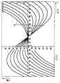
- Such quartz crystals Q usually have one of the temperature characteristics TK shown in FIG.
- the temperature characteristic curves TK are shown in an X / X coordinate system, the temperature changes T of the quartz crystal Q in degrees Celsius being indicated on the X axis and the resonance frequency deviations F from the nominal resonance frequency F of the quartz crystal being indicated on the Y axis.
- each temperature characteristic curve TK represented represents a group of temperature characteristic curves TK, each of which encompasses an ambient temperature range of +/- 1 ° C., the number of temperature characteristic curves TK becoming very large at small ambient temperature levels and which would mean a considerable amount of characteristic information.
- each temperature characteristic TK is assigned characteristic information ki.
- eleven characteristic information ki are provided for eleven temperature characteristics TK of a quartz crystal Q with an "AT cut".
- additional vibration-specific information ki such as a shift in the temperature characteristics TK caused by the aging of the quartz crystals Q, can be assigned.
- the temperature in the voltage-controlled oscillator gate circuit VCOS is measured.
- an oscillating crystal QM is used in the measuring oscillator MO, in which temperature changes cause the largest possible resonance frequency deviations. This is achieved with special quartz crystals with other quartz cuts.
- the measurement signals ms formed in the measuring oscillator MO are forwarded to the processing device VE, where the frequency change is determined and the temperature change is calculated therefrom.
- these measurement signals ms are modified or influenced according to the invention as a function of the characteristic information ki of the oscillating crystal Q used in the oscillator circuit VCOS.
- a divider DIV is arranged in the oscillator circuit VCOS, at the input E of which the measurement signals ms are controlled.
- the dividing device DIV is implemented, for example, by means of a binary counter, the counting rhythm of which can be set by means of identification information ki which is supplied by binary-coded information.
- the divisor of the divider DIV is determined by the counting rhythms.
- the temperature characteristics TK With reference to the temperature characteristics TK according to FIG. 2, eleven division factors are required in order to assign eleven temperature characteristics TK to the measurement signal ms.
- the assignment of the temperature characteristics TK which the quartz crystal Q used in the oscillator circuit VCOS has is achieved by entering the quartz crystal-specific characteristic information ki representing the respective temperature characteristic curve TK into the memory SP.
- the memory SP is implemented, for example, by a non-volatile, programmable memory (PROM) or by four switching elements, since four switching elements, with the aid of which 2 3 coded information can be formed, are sufficient for eleven temperature characteristics TK.
- the measurement signals ms are divided according to the assigned divisor and transmitted via the output AM of the oscillator circuit VCOS to an input EM of the processing device VE.
- the divided measurement signals msd are transmitted via corresponding connections to a first and to a second evaluation unit AE1, AE2.
- the relatively small frequency changes caused by the temperature changes in the oscillator circuit VCOS are recognized or evaluated in the first evaluation unit AE1 and the evaluation result is transmitted to a microprocessor device MP via a local bus LB.
- the divisor caused by the identification information ki in the dividing device DIV is determined by frequency measurement, from which the binary-coded information ki and the temperature characteristic TK of the quartz crystal Q can be derived.
- the evaluation of the digital, divided measurement signals msd is possible by means of a second evaluation device AE2 implemented in terms of circuitry and program technology. Since the processing device VE usually has a microprocessor MP, the first and second evaluation units AE1, AE2 are preferably implemented by a program in the microprocessor MP.
- the identification information ki derived in the second evaluation unit AE2 is transmitted to the microprocessor device MP via the local bus LB.
- the temperature characteristic information TK1 ... TK11 which is stored in a memory SPE connected to the local bus LB and represents a group of temperature characteristics Tk, is read out and processed accordingly.
- a phase comparison device PE is also provided in the processing device VE, to which the reference clock signals rts and the clock signals ts are transmitted and their phase is compared.
- the phase comparison signals are transmitted to a processing program VP in the microprocessor MP, processed there in accordance with the phase-locked loop and transmitted via an analog-digital converter AD to a voltage input VE of the oscillator circuit VCOS.
- the divider must be inserted between the output A of the oscillator circuit VCOS and the oscillator VCO - is shown in broken lines -.
- the clock signals ts in the processing device VE after the divisor has been determined are to be multiplied accordingly.
- the clock signals ts or measurement signals ms can be inserted with pulse duration or pulse pause modulating devices.
- this embodiment variant slightly increases the complexity of the oscillator circuit VCOS, extensive digital processing is possible in the processing device VE, as a result of which the processing device VE can be implemented predominantly in a microprocessor MP.
Landscapes
- Oscillators With Electromechanical Resonators (AREA)
- Stabilization Of Oscillater, Synchronisation, Frequency Synthesizers (AREA)
Abstract
Description
In taktgesteuerten, insbesondere nachrichtentechischen Einrichtungen sind aufgrund erhöhter Stabilitäts- und Sicherheitsanforderungen Oszillatorschaltungen überwiegend mit Schwingquarzen realisiert. Die Schwingquarze weisen in Abhängigkeit von den Quarzschnitten unterschiedliche temperaturabhängige Resonanzfrequenzen auf. Die Temperaturabhängigkeit ist durch eine schwingquarzindividuelle Temperaturkennlinie bzw. Kenninformation definiert, die bei der Quarzherstellung ermittelt bzw. gemessen wird. Diese temperaturbezogenen und weitere schwingquarzindividuelle Kenninformationen - z.B. Änderung der Schwingquarzeigenschaften aufgrund der Alterung des Schwingquarzes - werden den Anwendern von Schwingquarzen - insbesondere in Oszillatorschaltungen - auf Datenblättern oder für jeden Quarz separat druckschriftlich mitgeteilt. Desweiteren sind Aufdrucke auf den Schwingquarzen bekannt, anhand derer die schwingquarzindividuellen Kenninformationen aus Datenblättern entnehmbar sind. Bevorzugt werden die Schwingquarze in Oszillatorschaltungen eingesetzt, in denen digitale Taktsignale mit einer durch den Schwingquarz vorgegebenen Frequenz gebildet werden. Durch die individuellen Eigenschaften der Schwingquarze müssen in den die digitale Taktsignale verarbeitenden und an die Oszillatorschaltung angeschlossenen Takteinrichtungen - insbesondere in phasenregelkreisgesteuerten Takteinrichtungen - für hochgenaue Taktsteuerungen die schwingquarzindividuellen Kenninformationen verfügbar sein. Da zunehmend in den Takteinrichtungen durch Programme realisierte Taktsteuerungsverfahren vorgesehen sind, erfolgt die Eingabe der schwingquarzindividuellen Kenninformationen der zugeordneten Oszillatorschaltung für jede Taktsteuerung separat. Dies bedeutet einen erheblichen zusätzlichen Aufwand bei der Zuordnung einer Oszillatorschaltung zu einer Takteinrichtung bzw. zu einer Einrichtung, in der eine hochpräzise Verarbeitung der Taktsignale stattfindet und in der folglich die schwingquarzindividuellen Kenninformationen einzubringen sind.In clock-controlled, especially communications technology facilities, oscillator circuits are predominantly implemented with quartz crystals due to increased stability and safety requirements. The quartz crystals have different temperature-dependent resonance frequencies depending on the quartz cuts. The temperature dependency is defined by a temperature characteristic curve or characteristic information that is specific to oscillating quartz and is determined or measured during quartz production. This temperature-related and other individual quartz crystal-specific information - eg changes in the quartz crystal properties due to the aging of the quartz crystal - are communicated to the users of quartz crystals - especially in oscillator circuits - on data sheets or for each quartz separately in printed form. Furthermore, imprints on the quartz crystals are known, by means of which the quartz-individual-specific identification information can be extracted from data sheets. The quartz crystals are preferably used in oscillator circuits in which digital clock signals are formed with a frequency predetermined by the quartz crystal. Due to the individual properties of the quartz crystals, the quartz-individual-specific information must be available in the clock devices processing the digital clock signals and connected to the oscillator circuit - in particular in phase-locked loop-controlled clock devices - for highly precise clock controls. Since clock control methods implemented by programs are increasingly provided in the clock devices, the quartz-individual-specific characteristic information of the assigned oscillator circuit is entered for each clock control separately. This means a considerable additional effort when assigning an oscillator circuit to a clock device or to a device in which high-precision processing of the clock signals takes place and in which the characteristic quartz oscillation-specific information must consequently be introduced.
Der Erfindung liegt daher die Aufgabe zugrunde, diesen erheblichen Aufwand für das Einbringen der schwingquarzindividuellen Kenninformationen in die an die jeweilige Oszillatorschaltung angeschlossene weiterverarbeitende Einrichtung zu reduzieren. Die Aufgabe wird ausgehend von einer Oszillatorschaltung gemäß dem Oberbegriff des Anspruchs 1 durch dessen kennzeichnende Merkmale gelöst.The invention is therefore based on the object of reducing this considerable outlay for introducing the quartz-individual-specific characteristic information into the further processing device connected to the respective oscillator circuit. The object is achieved on the basis of an oscillator circuit according to the preamble of
Der wesentliche Aspekt der erfindungsgemäßen Oszillatorschaltung ist darin zu sehen, daß in dieser ein die schwingquarzindividuellen Informationen speicherndes Mittel angeordnet und derart ausgestaltet ist, daß die schwingwquarzindividuellen Kenninformationen als analoge, digitale, codierte digitale Signale oder modulierte Signale an einen Ausgang der Oszillatorschaltung gesteuert werden. Die schwingquarzindividuellen Informationen werden hierbei vorzugsweise beim Herstellen der Oszillatorschaltung eingespeichert. Der wesentliche Vorteil der erfindungsgemäßen Oszillatorschaltung ist darin zu sehen, daß nach einem einmaligen Einspeichern der schwingquarzindividuellen Kenninformationen diese Kenninformation ständig an einem Ausgang der Oszillatorschaltung den weiterverarbeitenden Einrichtungen zur Verfügung stehen und somit bei Anschluß oder Wechsel einer weiterverarbeitenden Einrichtung nicht mehr durch aufwendiges Einspeichern eingebracht werden müssen.The essential aspect of the oscillator circuit according to the invention can be seen in the fact that a means storing the quartz-crystal-specific information is arranged and configured in such a way that the quartz-crystal-specific information is controlled as analog, digital, coded digital signals or modulated signals at an output of the oscillator circuit. The individual quartz crystal information is preferably stored when the oscillator circuit is manufactured. The main advantage of the oscillator circuit according to the invention can be seen in the fact that after the oscillating-crystal-specific identification information has been stored once, this identification information is continuously available to the further processing devices at an output of the oscillator circuit and thus no longer has to be introduced by complex storing when connecting or changing a further processing device .
Besonders vorteilhaft wird bei einem Bilden von digitalen Taktsignalen in der Oszillatorschaltung das die schwingquarzindividuellen Kenninformationen speichernde Mittel durch ein Mittel zur Beeinflussung der Taksignale realisiert - Anspruch 2. Hierbei werden die schwingquarzindividuellen Kenninformationen zusammen mit den Taktsignalen an den bereits vorhandenen Ausgang für die Taktsignale geführt, wobei die Taktsignale in Abhängigkeit von den gespeicherten schwingquarzindividuellen Kenninformationen beeinflußt werden. Diese Möglichkeit der Beeinflussung ist des weiteren für Taktsignale möglich, die in einem in der Oszillatorschaltung angeordneten Meßoszillator gebildet werden - Anspruch 3. Mit Hilfe des Meßoszillators wird die aktuelle Temperatur der Oszillatorschaltung gemessen und die gebildeten Meßsignale - vorzugsweise digitale Meßsignale - werden über einen Meßausgang der Oszillatorschaltung an weiterverarbeitende Einrichtungen geführt. Die wesentlichen Eigenschaften einer Temperaturoszillatorschaltung sind darin zu sehen, daß Temperaturänderungen möglichst hohe Frequenzänderungen der gebildeten Meßsignale hervorrufen.When the digital clock signals are formed in the oscillator circuit, the means storing the quartz-individual-specific characteristic information is particularly advantageous realized by a means for influencing the clock signals - claim 2. Here, the quartz-individual identification information together with the clock signals are routed to the already existing output for the clock signals, the clock signals being influenced as a function of the stored quartz-individual identification information. This possibility of influencing is also possible for clock signals which are formed in a measuring oscillator arranged in the oscillator circuit - claim 3. With the help of the measuring oscillator, the current temperature of the oscillator circuit is measured and the measuring signals formed - preferably digital measuring signals - are via a measuring output of the Oscillator circuit led to further processing facilities. The essential properties of a temperature oscillator circuit can be seen in the fact that temperature changes cause the highest possible frequency changes in the measurement signals formed.
Eine wesentliche schwingquarzindividuelle Kenninformation stellt die Temperaturkennlinie eines Schwingquarzes dar, wobei die Temperaturkennlinien die Resonanzfrequenzen des jeweiligen Schwingquarzes in Abhängigkeit von der Umgebungstemperatur angeben. Um den Umfang der schwingquarzindividuellen Kenninformationen zu begrenzen, wird einer schwingquarzindividuellen Kenninformation eine Gruppe von Temperaturkennlinien zugeordnet - Anspruch 5. Die Größe der zugeordneten Gruppe von Temperaturkennlinien ist hierbei auf die geforderte Genauigkeit an die Frequenzstabilität der gebildeten Taktsignale abzustimmen. Dies bedeutet, daß bei steigenden Genauigkeitsanforderungen die Anzahl der Temperaturkennlinien je Gruppe zu vermindern ist.The characteristic temperature curve of a quartz crystal represents essential quartz-individual characteristic information, the temperature characteristic curves indicating the resonance frequencies of the respective quartz crystal as a function of the ambient temperature. In order to limit the scope of the quartz-individual characteristic information, a group of temperature characteristic curves is assigned to a quartz-individual characteristic information. The size of the assigned group of temperature characteristic curves is to be matched to the required accuracy of the frequency stability of the clock signals formed. This means that with increasing accuracy requirements, the number of temperature characteristics per group has to be reduced.
Gemäß einer vorteilhaften Ausgestaltung der Oszillatorschaltung sind die Mittel zur Beeinflussung der Taktsignale oder Meßsignale
- durch eine die Signalpulsdauer- bzw. Pulspause modulierende Modulationseinrichtung, oder
- durch eine die Signalfrequenz vorgegeben ändernde Frequenzeinstelleinrichtung, oder
- durch eine den Signalpegel variierende Pegeleinrichtung, oder
- durch eine die Impedanz des Ausgangs der Oszillatorschaltung variierende Impendanzeinrichtung realisiert
- Anspruch 6.
- by a modulation device that modulates the signal pulse duration or pulse pause, or
- by a frequency setting device which changes the signal frequency, or
- by a level device which varies the signal level, or
- realized by an impedance device which varies the impedance of the output of the oscillator circuit
- Claim 6.
Eine besonders vorteilhafte Variante stellt hierbei die Pulsdauer- bzw. Pulspausenmodulation der Taktsignale bzw. der Meßsignale dar, da hierbei durch Zusammenfassen mehrerer Taktsignale bzw. Meßsignale eine codierte, beliebig umfangreiche Information gebildet und an eine weiterverarbeitende Einrichtung übermittelbar ist. Die Beeinflussung der Taktsignale bzw. Meßsignale wird hierbei durch bekannte Modulationseinrichtungen, Frequenzeinstelleinrichtungen, Pegeleinrichtungen und Impedanzeinrichtungen realisiert.A particularly advantageous variant is the pulse duration or pulse pause modulation of the clock signals or the measurement signals, since by combining a plurality of clock signals or measurement signals, coded, arbitrarily extensive information is formed and can be transmitted to a further processing device. The influencing of the clock signals or measurement signals is implemented by known modulation devices, frequency setting devices, level devices and impedance devices.
Die Mittel zur Speicherung der schwingquarzindividuellen Kenninformationen bzw. Temperaturkennlinien-Information sind vorteilhaft durch einstellbare, eine digitale Information bildende Einstellmittel oder programmierbare Speichermittel realisiert - Anspruch 7. Die Einstellmittel sind beispielsweise durch Schaltelemente oder Codierschaltelemente gebildet, die beim Herstellen einer Oszillatorschaltung, d.h. bei der Fertigung eines Taktksignale erzeugenden Taktoszillators, entsprechend der aktuell gemessenen Temperaturkennlinie des Schwingqzuarzes eingestellt werden. Alternativ hierzu kann die Temperaturkennlinien-Information in einen in der Oszillatorschaltung angeordneten programmierbaren Speicher der Oszillatorschaltung einmalig eingespeichert werden. Diese Einspeicherung ist nur bei einem Wechsel des Schwingquarzes in der jeweiligen Oszillatorschaltung zu ändern.The means for storing the quartz-individual characteristic information or temperature characteristic information are advantageously implemented by adjustable setting means which form digital information or programmable storage means - claim 7. The setting means are formed, for example, by switching elements or coding switching elements which are used in the manufacture of an oscillator circuit, ie during production of a clock oscillator generating clock signals, can be set in accordance with the currently measured temperature characteristic of the oscillating crystal. As an alternative to this, the temperature characteristic curve information can be stored once in a programmable memory of the oscillator circuit arranged in the oscillator circuit be saved. This storage can only be changed when the quartz crystal in the respective oscillator circuit changes.
Für eine Bewertung bzw. Auswertung der modifizierten bzw. beeinflußten Takt- oder Meßsignale ist in einer an den Ausgang bzw. den Meßausgang der Oszillatorschaltung angeschlossene weiterverarbeitende Einrichtung ein Mittel zum Erkennen und Bewerten der modifizierten bzw. beeinflußten Takt- oder Meßsignale angeordnet und derart ausgestaltet, daß die schwingquarzindividuellen Informationen aus dem zugeführten modifizierten bzw. beeinflußten Takt- bzw. Meßsignal abgeleitet werden können - Anspruch 8. Analog zu den Mitteln zur Beeinflussung der Taktsignale oder Meßsignale sind in den weiterverarbeitenden Einrichtungen die Mittel zum Erkennen und Bewerten der modifizierten Taktsignale durch eine die Pulsdauer- bzw. die pulspausenmodulierten Takt- bzw. Meßsignale demodulierende Demodulationseinrichtung, durch eine die vorgegeben geänderte Taktsignal- bzw. Meßsignalfrequenz erkennende Frequenzmeßeinrichtung, oder durch eine den Pegel der Taktsignale bzw. Meßsignale oder die Impedanz des Ausgangs oder Meßausgangs der Oszillatorschaltung messende Pegelmeßeinrichtung bzw. Impedanzmeßeinrichtung realisiert - Anspruch 9. Besonders vorteilhaft ist in mikroprozessorgesteuerten, die digitale Signale weiterverarbeitenden Einrichtungen eine die Pulsdauer- bzw. pulspausenmodulierten Takt-bzw. Meßsignale demodulierende Demodulationseinrichtung realisierbar, da bei einem durch mehrere Taktsignale bzw. Meßsignale gebildete Impulstelegramm jedem Taktsignal lediglich zwei Informationszustände zugeordnet und damit auf eine digitale Informationsverarbeitung bzw. Weiterverarbeitung abgestimmt sind.For an evaluation or evaluation of the modified or influenced clock or measurement signals, a means for recognizing and evaluating the modified or influenced clock or measurement signals is arranged in a further processing device connected to the output or the measurement output of the oscillator circuit, and is designed in such a way that that the individual quartz crystal information can be derived from the supplied modified or influenced clock or measurement signal - claim 8. Analogous to the means for influencing the clock signals or measurement signals in the further processing devices are the means for recognizing and evaluating the modified clock signals by a Pulse duration or the pulse pause modulated clock or measuring signals demodulating device, by a frequency measuring device recognizing the predetermined changed clock signal or measuring signal frequency, or by a level of the clock signals or measuring signals or the I Level measurement device or impedance measurement device measuring the impedance of the output or measurement output of the oscillator circuit is realized. Claim 9 is particularly advantageous in microprocessor-controlled devices which further process the digital signals, a pulse duration or pulse pause modulated clock or. Measuring signal demodulating demodulation device can be implemented, since in the case of a pulse telegram formed by a plurality of clock signals or measuring signals, only two information states are assigned to each clock signal and are therefore matched to digital information processing or further processing.
Im folgenden wird die Erfindung anhand von Zeichnungen näher erläutert. Dabei zeigen
Figur 1- ein Blockschaltbild eines Phasenregelkreises, und
- Figur 2
- ein Diagramm, in dem Temperaturkennlinien von Quarzen mit "AT-Schnitt" dargestellt sind.
- Figure 1
- a block diagram of a phase locked loop, and
- Figure 2
- a diagram in which the temperature characteristics of quartzes with "AT cut" are shown.
Figur 1 zeigt einen Phasenregelkreis PLL, der durch eine spannungsgesteuerte Oszillatorschaltung VCOS und eine Verarbeitungseinrichtung VE gebildet ist. Die Funktion eines Phasenregelkreises PLL ist darin zu sehen, die in der spannungsgesteuerten Oszillatorschaltung VCOS gebildeten Taktsignale ts phasensynchron zu an den Phasenregelkreis PLL geführten Referenztaktsignalen rts zu regeln. Der Phasenregelkreis PLL ist beispielsweise in der zentralen Takteinrichtung eines Kommunikationssystems angeordnet, wobei die gebildeten Taktsignale ts synchron zu ankommenden Referenztaktsignalen rts einer übergeordneten Takteinrichtung zu steuern sind.FIG. 1 shows a phase-locked loop PLL, which is formed by a voltage-controlled oscillator circuit VCOS and a processing device VE. The function of a phase-locked loop PLL can be seen in that the clock signals ts formed in the voltage-controlled oscillator circuit VCOS are regulated in phase synchronization with reference clock signals rts fed to the phase-locked loop PLL. The phase locked loop PLL is arranged, for example, in the central clock device of a communication system, the clock signals ts formed being to be controlled in synchronism with incoming reference clock signals rts of a higher-level clock device.
Für das Ausführungsbeispiel sei angenommen, daß die Spannungsgesteuerte Oszillatorschaltung VCOS einen die Taktsignale ts bildenden, spannungsgesteuerten Oszillator VCO sowie einen Meßsignale ms bildenden Meßoszillator MO aufweist. Die Taktsignalfrequenz der Taktsignale ts ist durch einen Schwingquarz Q bestimmt. Für das Ausführungsbeispiel sei angenommen, daß ein Schwingquarz Q mit "AT-Schnitt" eingesetzt wird. Derartige Schwingquarze Q weisen üblicherweise eine der in Figur 2 dargestellte Temperaturkennlinien TK auf. Die Temnperaturkennlinien TK sind in einem X/X-Koordinatensystem dargestellt, wobei auf der X-Achse die Temperaturänderungen T des Schwingquarzes Q in Grad Celsius und auf der Y-Achse die Resonanzfrequenzabweichungen F von der Resonanznennfrequenz F des Schwingquarzes angegeben sind.For the exemplary embodiment, it is assumed that the voltage-controlled oscillator circuit VCOS has a voltage-controlled oscillator VCO forming the clock signals ts and a measuring oscillator MO forming measuring signals ms. The clock signal frequency of the clock signals ts is determined by a quartz crystal Q. For the exemplary embodiment it is assumed that an oscillating quartz Q with an "AT cut" is used. Such quartz crystals Q usually have one of the temperature characteristics TK shown in FIG. The temperature characteristic curves TK are shown in an X / X coordinate system, the temperature changes T of the quartz crystal Q in degrees Celsius being indicated on the X axis and the resonance frequency deviations F from the nominal resonance frequency F of the quartz crystal being indicated on the Y axis.
In Fig. 2 repräsentiert jede dargestellte Temperaturkennlinie TK eine Gruppe von Temperaturkennlinien TK, die jeweils einer Umgebungstemperaturbereich von +/- 1 °C umfassen, wobei die Anzahl von Temperaturkennlinien TK bei kleinen Umgebungstemperaturstufen sehr groß wird und einen erheblichen Umfang an Kenninformationen bedeuten würde.In FIG. 2, each temperature characteristic curve TK represented represents a group of temperature characteristic curves TK, each of which encompasses an ambient temperature range of +/- 1 ° C., the number of temperature characteristic curves TK becoming very large at small ambient temperature levels and which would mean a considerable amount of characteristic information.
Für das Ausführungsbeispiel sei des weiteren angenommen, daß jeder Temperaturkennlinie TK eine Kenninformation ki zugeordnet ist. Dies bedeutet, daß für elf Temperaturkennlinien TK eines Schwingquarz Q mit "AT-Schnitt" elf Kenninformation ki vorgesehen sind. Neben diesen Temperaturkennlinien TK können weitere schwingwarzindividuelle Kenninformationen ki, wie z.B. eine durch die Alterung der Schwingquarze Q hervorgerufene Verschiebung der Temperaturkennlinien TK, zugeordnet werden. Mit Hilfe des in der spannungsgesteuerten Oszillatorschaltung VCOS angeordneten Meßoszillators MO wird die Temperatur in der spannungsgesteuerten Oszilltorschaltung VCOS gemessen. Hierzu wird im Meßoszillator MO ein Schwingquarz QM eingesetzt, bei dem Temperaturänderungen möglichst große Resonanzfrequenzabweichungen verursachen. Dies wird durch spezielle Meßschwingquarze mit anderen Quarzschnitten erreicht. Die im Meßoszilltor MO gebildeten Meßsignale ms werden an die Verarbeitungseinrichtung VE weitergeleitet, dort die Frequenzänderung festgestellt und daraus die Temperaturänderung berechnet. Für das Ausführungsbeispiel sei angenommen, daß diese Meßsignale ms erfindungsgemäß in Abhängigkeit von der Kenninformation ki des in der Oszillatorschaltung VCOS eingesetzten Schwingquarzes Q modifiziert bzw. beeinflußt werden. Dies wird dadurch erreicht, daß in der Oszillatorschaltung VCOS eine Dividiereinrichtung DIV angeordnet ist, an dessen Eingang E die Meßsignale ms gesteuert werden. Die Dividiereinrichtung DIV ist beispielsweise durch einen binären Zähler realisiert, dessen Zählrhythmus durch zugeführte binär codierte Informationen repräsentierende Kenninformationen ki einstellbar ist. Durch die Zählrhythmen wird der Divisor der Dividiereinrichtung DIV bestimmt. Bezogen auf die Figur 2 gemäßen Temperaturkennlinien TK sind elf Divisionsfaktoren erforderlich, um dem Meßsignal ms elf Temperaturkennlinien TK zuzuordnen. Die Zuordnung der Temperaturkennlinien TK, die der in der Oszillatorschaltung VCOS eingesetzte Schwingquarz Q aufweist, wird durch Eingeben der die jeweilige Temperaturkennlinie TK repräsentierende schwingquarzindividuelle Kenninformation ki in den Speicher SP erreicht. Der Speicher SP ist beispielsweise durch einen nichtflüchtigen, programmierbaren Speicher (PROM) oder durch vier Schaltelemente realisiert, da für elf Temperaturkennlinien TK vier Schaltelemente, mit deren Hilfe 23 codierte Informationen gebildet werden können, ausreichen. Entsprechend der eingegegbenen codierten binären Information ki werden die Meßsignale ms entsprechend dem zugeordneten Divisor dividiert und über den Ausgang AM der Oszillatorschaltung VCOS an einen Eingang EM der Verarbeitungseinrichtung VE übermittelt. In der Verarbeitungseinrichtung VE werden die dividierten Meßsignale msd über entsprechende Verbindungen an eine erste und an eine zweite Auswerteeinheit AE1, AE2 übermittelt. In der ersten Auswerteeinheit AE1 werden die durch die Temperaturänderungen in der Oszillatorschaltung VCOS hervorgerufenen relativ kleinen Frequenzänderungen erkannt bzw. bewertet und das Bewertungsergebnis über einen lokalen Bus LB an eine Mikroprozessoreinrichtung MP übermittelt. In der zweiten Auswerteeinheit AE2 wird durch Frequenzmessung der durch die Kenninformation ki in der Dividiereinrichtung DIV bewirkte Divisor ermittelt, woraus die binär codierte Information ki sowie die Temperaturkennline TK des Schwingquarzes Q abgeleitet werden kann. Die Auswertung der digitalen, dividierten Meßsignale msd ist durch eine schaltungstechnisch und programmtechnisch realisierte zweite Auswerteeinrichtung AE2 möglich. Da die Verarbeitungseinrichtung VE üblicherweise einen Mikroprozessor MP aufweist, wird die erste und zweite Auswerteeinheit AE1, AE2 vorzugsweise per Programm im Mikroprozessor MP realisiert.For the exemplary embodiment it is further assumed that each temperature characteristic TK is assigned characteristic information ki. This means that eleven characteristic information ki are provided for eleven temperature characteristics TK of a quartz crystal Q with an "AT cut". In addition to these temperature characteristics TK, additional vibration-specific information ki, such as a shift in the temperature characteristics TK caused by the aging of the quartz crystals Q, can be assigned. With the aid of the measuring oscillator MO arranged in the voltage-controlled oscillator circuit VCOS, the temperature in the voltage-controlled oscillator gate circuit VCOS is measured. For this purpose, an oscillating crystal QM is used in the measuring oscillator MO, in which temperature changes cause the largest possible resonance frequency deviations. This is achieved with special quartz crystals with other quartz cuts. The measurement signals ms formed in the measuring oscillator MO are forwarded to the processing device VE, where the frequency change is determined and the temperature change is calculated therefrom. For the exemplary embodiment it is assumed that these measurement signals ms are modified or influenced according to the invention as a function of the characteristic information ki of the oscillating crystal Q used in the oscillator circuit VCOS. This is achieved in that a divider DIV is arranged in the oscillator circuit VCOS, at the input E of which the measurement signals ms are controlled. The dividing device DIV is implemented, for example, by means of a binary counter, the counting rhythm of which can be set by means of identification information ki which is supplied by binary-coded information. The divisor of the divider DIV is determined by the counting rhythms. With reference to the temperature characteristics TK according to FIG. 2, eleven division factors are required in order to assign eleven temperature characteristics TK to the measurement signal ms. The assignment of the temperature characteristics TK which the quartz crystal Q used in the oscillator circuit VCOS has is achieved by entering the quartz crystal-specific characteristic information ki representing the respective temperature characteristic curve TK into the memory SP. The memory SP is implemented, for example, by a non-volatile, programmable memory (PROM) or by four switching elements, since four switching elements, with the aid of which 2 3 coded information can be formed, are sufficient for eleven temperature characteristics TK. In accordance with the coded binary information ki entered, the measurement signals ms are divided according to the assigned divisor and transmitted via the output AM of the oscillator circuit VCOS to an input EM of the processing device VE. In the processing device VE, the divided measurement signals msd are transmitted via corresponding connections to a first and to a second evaluation unit AE1, AE2. The relatively small frequency changes caused by the temperature changes in the oscillator circuit VCOS are recognized or evaluated in the first evaluation unit AE1 and the evaluation result is transmitted to a microprocessor device MP via a local bus LB. In the second evaluation unit AE2, the divisor caused by the identification information ki in the dividing device DIV is determined by frequency measurement, from which the binary-coded information ki and the temperature characteristic TK of the quartz crystal Q can be derived. The evaluation of the digital, divided measurement signals msd is possible by means of a second evaluation device AE2 implemented in terms of circuitry and program technology. Since the processing device VE usually has a microprocessor MP, the first and second evaluation units AE1, AE2 are preferably implemented by a program in the microprocessor MP.
Die in der zweiten Auswerteeinheit AE2 abgeleitete Kenninformation ki wird über den lokalen Bus LB an die Mikroprozessoreinrichtung MP übermittelt. Mit Hilfe eines mikroprozessorgeeignetenProgrammes werden die in einem an den lokalen Bus LB angeschlossenen Speicher SPE hinterlegten, jeweiles eine Gruppe von Temperaturkennlinien Tk repräsentierenden Temperaturkennlinien-Informationen TK1 ... TK11 entsprechend der ermittelten Kenninformation ki ausgelesen und entsprechend weiterverarbeitet.The identification information ki derived in the second evaluation unit AE2 is transmitted to the microprocessor device MP via the local bus LB. With the help of a microprocessor-suitable program, the temperature characteristic information TK1 ... TK11, which is stored in a memory SPE connected to the local bus LB and represents a group of temperature characteristics Tk, is read out and processed accordingly.
In der Verarbeitungseinrichtung VE ist des weiteren eine Phasenvergleichseinrichtung PE vorgesehen, an die die Referenztaktsignale rts und die Taktsignale ts übermittelt und hinsichtlich ihrer Phase verglichen werden. Die Phasenvergleichssignale werden an ein Verarbeitungsprogramm VP im Mikroprozessor MP übermittelt, dort phasenregelkreisgemäß aufbereitet und über einen Analog-Digital-Wandler AD an einen Spannungseingang VE der Oszillatorschaltung VCOS übermittelt.A phase comparison device PE is also provided in the processing device VE, to which the reference clock signals rts and the clock signals ts are transmitted and their phase is compared. The phase comparison signals are transmitted to a processing program VP in the microprocessor MP, processed there in accordance with the phase-locked loop and transmitted via an analog-digital converter AD to a voltage input VE of the oscillator circuit VCOS.
Alternativ, - beispielsweise bei Fehlen eines Meßoszillators MO, ist die Dividiereinrichtung zwischen den Ausgang A der Oszillatorschaltung VCOS und dem Oszillator VCO einzufügen - ist strichliert dargestellt - . Hierbei ist zu beachten, daß in der Verarbeitungseinrichtung VE nach dem Feststellen des Divisors die Taktsignale ts entsprechend zu multiplizieren sind. Des weiteren können anstelle der Divisionseinrichtungen DIV die Taktsignale ts bzw. Meßsignale ms pulsdauer- oder pulspausen- modulierende Einrichtungen eingefügt werden. Diese Ausführungsvariante erhöht zwar den Aufwand der Oszillatorschaltung VCOS geringfügig, jedoch ist in der Verarbeitungseinrichtung VE eine weitgehende digitale Verarbeitung möglich, wodurch die Verarbeitungseinrichtung VE überwiegend in einem Mikroprozessor MP realisierbar ist.Alternatively, - for example in the absence of a measuring oscillator MO, the divider must be inserted between the output A of the oscillator circuit VCOS and the oscillator VCO - is shown in broken lines -. It should be noted here that the clock signals ts in the processing device VE after the divisor has been determined are to be multiplied accordingly. Furthermore, instead of the division devices DIV, the clock signals ts or measurement signals ms can be inserted with pulse duration or pulse pause modulating devices. Although this embodiment variant slightly increases the complexity of the oscillator circuit VCOS, extensive digital processing is possible in the processing device VE, as a result of which the processing device VE can be implemented predominantly in a microprocessor MP.
Claims (9)
- Oscillator circuit (VCOS) having a quartz crystal oscillator (Q) having characteristic information (ki) specific to the quartz crystal oscillator, alternating signals (ts) formed in the oscillator circuit (VCOS) being led to an output (A), characterized in that means storing an item (ki) of characteristic information specific to the quartz crystal oscillator are configured in such a way in the oscillator circuit that the characteristic information (ki) specific to the quartz crystal oscillator is directed to at least one output (A, AM) of the oscillator circuit (VCOS) as analogue, digital, coded digital or modulated signals (msd).
- Oscillator circuit according to Claim 1, characterized in that the oscillator circuit (VCOS) is configured such that digital clock signals (ts) are formed and led to a clock signal output (A), in that the means storing the characteristic information (ki) specific to the quartz crystal oscillator are implemented by means (DIV) for influencing the clock signals (ts) and are configured such that the clock signals (ts) formed are influenced as a function of the stored characteristic information (ki) specific to the quartz crystal oscillator.
- Oscillator circuit according to Claim 1 or 2, characterized in that a measuring oscillator (MO) provided for temperature measurement of the oscillator circuit (VCOS) is arranged in the oscillator circuit (VCOS), the measurement signals (ms) formed being led to a measuring output (AM) of the oscillator circuit (VCOS) and in that the means storing the characteristic information (ki) specific to the quartz crystal oscillator are implemented by means (DIV) for influencing the measurement signals (ms) and are configured such that the measurement signals (ms) formed are influenced as a function of the stored characteristic information (ki) specific to the quartz crystal oscillator.
- Oscillator circuit according to one of the preceding claims, characterized in that the characteristic information (ki) representing the temperature characteristic (TK) of the respective quartz crystal oscillator (Q) is stored in the means (SP) storing the characteristic information (ki) specific to the quartz crystal oscillator.
- Oscillator circuit according to Claim 4, characterized in that the characteristic information (ki) specific to the quartz crystal oscillator is respectively assigned a prescribed group of temperature characteristics (TK) of the respective quartz crystal oscillator (Q).
- Oscillator circuit according to one of the preceding claims, characterized in that the means for influencing the clock signals (ts) or measurement signals (ms) are implemented by- a modulation device modulating the signal pulse duration or pulse pause, or- by a frequency-setting device (DIV) which changes the signal frequency in a prescribed manner, or- a level device which varies the signal level,- or by an impedance device which varies the impedance of the output (A) or measuring output (AM) of the oscillator circuit (VCOS).
- Oscillator circuit according to one of the preceding claims, characterized in that the means for storing the characteristic information (ki) specific to the quartz crystal oscillator are implemented by adjustable setting means which form digital information, or by programmable storage means, the digital, coded information representing the characteristic information (ki) specific to the quartz crystal oscillator and controlling the means (DIV) for influencing the clock and measurement signals (ts, ms), respectively.
- Oscillator circuit according to one of the preceding claims, characterized in that means (AE2) for detecting and evaluating the influenced clock or measurement signals (ts, ms), respectively, are arranged in a clock device (VE), which is connected to an output (A, AM), providing the clock signals (ts) or the measurement signals (ms), of the oscillator circuit (VCOS) and further processes the clock and measurement signals (ts, ms) respectively, and are configured in such a way that the characteristic information (ki) specific to the quartz crystal oscillator is derived from the clock and measurement signals (ts, ms), respectively, which have been fed and influenced.
- Oscillator circuit according to Claim 7, characterized in that the means for detecting and evaluating the modified clock or measurement signals (ts, ms) are implemented by- a demodulation device which demodulates the pulse-duration or pulse-pause modulated clock or measurement signals (ts, ms) respectively- a frequency-detection device (AE2) which detects the prescribed, changed clock-signal or measuring-signal frequency or- by a level-measuring device which measures the level of the clock signals or measurement signals (ts, ms) respectively,- or by an impedance-measuring device which measures the impedance of the output (A) or measuring output (AM) of the oscillator circuit (VCOS).
Applications Claiming Priority (2)
| Application Number | Priority Date | Filing Date | Title |
|---|---|---|---|
| DE4302542 | 1993-01-29 | ||
| DE4302542A DE4302542A1 (en) | 1993-01-29 | 1993-01-29 | Oscillator circuit with a memory storing the quartz-individual identification information |
Publications (2)
| Publication Number | Publication Date |
|---|---|
| EP0608681A1 EP0608681A1 (en) | 1994-08-03 |
| EP0608681B1 true EP0608681B1 (en) | 1997-04-23 |
Family
ID=6479233
Family Applications (1)
| Application Number | Title | Priority Date | Filing Date |
|---|---|---|---|
| EP94100070A Expired - Lifetime EP0608681B1 (en) | 1993-01-29 | 1994-01-04 | Oscillator circuit with a memory for memorising characteristic information individual to the quartz vibrator |
Country Status (6)
| Country | Link |
|---|---|
| US (1) | US5574408A (en) |
| EP (1) | EP0608681B1 (en) |
| CN (1) | CN1092917A (en) |
| AT (1) | ATE152306T1 (en) |
| CA (1) | CA2114360A1 (en) |
| DE (2) | DE4302542A1 (en) |
Families Citing this family (28)
| Publication number | Priority date | Publication date | Assignee | Title |
|---|---|---|---|---|
| DE59500681D1 (en) * | 1994-12-28 | 1997-10-23 | Siemens Ag | Method for compensating the temperature response of an oscillator circuit |
| US6016080A (en) * | 1997-03-30 | 2000-01-18 | Zuta; Marc | Computer based fast phase difference measuring unit and PLL using same |
| US5883844A (en) * | 1997-05-23 | 1999-03-16 | Stmicroelectronics, Inc. | Method of stress testing integrated circuit having memory and integrated circuit having stress tester for memory thereof |
| DE69908355T2 (en) * | 1999-09-22 | 2004-04-08 | Telefonaktiebolaget L M Ericsson (Publ) | Circuit for temperature compensation for coordinated crystals |
| US20060267194A1 (en) | 2002-10-15 | 2006-11-30 | Sehat Sutardja | Integrated circuit package with air gap |
| US7768360B2 (en) * | 2002-10-15 | 2010-08-03 | Marvell World Trade Ltd. | Crystal oscillator emulator |
| US7760039B2 (en) * | 2002-10-15 | 2010-07-20 | Marvell World Trade Ltd. | Crystal oscillator emulator |
| US7148763B2 (en) * | 2002-10-15 | 2006-12-12 | Marvell World Trade Ltd. | Integrated circuit including processor and crystal oscillator emulator |
| US20060113639A1 (en) * | 2002-10-15 | 2006-06-01 | Sehat Sutardja | Integrated circuit including silicon wafer with annealed glass paste |
| US7791424B2 (en) * | 2002-10-15 | 2010-09-07 | Marvell World Trade Ltd. | Crystal oscillator emulator |
| US7042301B2 (en) * | 2002-10-15 | 2006-05-09 | Marvell International Ltd. | Crystal oscillator emulator |
| US7436227B2 (en) * | 2003-05-02 | 2008-10-14 | Silicon Laboratories Inc. | Dual loop architecture useful for a programmable clock source and clock multiplier applications |
| US7288998B2 (en) * | 2003-05-02 | 2007-10-30 | Silicon Laboratories Inc. | Voltage controlled clock synthesizer |
| US7187241B2 (en) * | 2003-05-02 | 2007-03-06 | Silicon Laboratories Inc. | Calibration of oscillator devices |
| US7064617B2 (en) * | 2003-05-02 | 2006-06-20 | Silicon Laboratories Inc. | Method and apparatus for temperature compensation |
| US7295077B2 (en) * | 2003-05-02 | 2007-11-13 | Silicon Laboratories Inc. | Multi-frequency clock synthesizer |
| US7375597B2 (en) | 2005-08-01 | 2008-05-20 | Marvell World Trade Ltd. | Low-noise fine-frequency tuning |
| US7872542B2 (en) * | 2005-08-01 | 2011-01-18 | Marvell World Trade Ltd. | Variable capacitance with delay lock loop |
| US7852098B2 (en) * | 2005-08-01 | 2010-12-14 | Marvell World Trade Ltd. | On-die heating circuit and control loop for rapid heating of the die |
| US20090108949A1 (en) * | 2007-10-30 | 2009-04-30 | Qualcomm Incorporated | Temperature compensation for crystal oscillators |
| KR100861087B1 (en) | 2007-12-28 | 2008-09-30 | 엔셋주식회사 | Temperature compensated crystal oscillator using multi-chip and method for manufacturing the same |
| US20090195322A1 (en) * | 2008-01-31 | 2009-08-06 | Qualcomm Incorporated | Crystal oscillator frequency calibration |
| WO2011016732A1 (en) | 2008-11-28 | 2011-02-10 | Rakon Limited | Frequency reference correction for temperature-frequency hysteresis error |
| JP2013232836A (en) * | 2012-05-01 | 2013-11-14 | Nippon Dempa Kogyo Co Ltd | Oscillation device |
| JP6177614B2 (en) * | 2013-07-29 | 2017-08-09 | 日本電波工業株式会社 | Oscillator |
| DE102015213977A1 (en) * | 2015-07-23 | 2017-01-26 | Fraunhofer-Gesellschaft zur Förderung der angewandten Forschung e.V. | Standard-based radio signal Modifying data transmitter |
| CN108345352B (en) | 2017-01-24 | 2024-03-05 | 精工爱普生株式会社 | Circuit device, oscillation device, physical quantity measuring device, electronic apparatus, and moving object |
| JP6972562B2 (en) * | 2017-01-24 | 2021-11-24 | セイコーエプソン株式会社 | Circuit devices, oscillation devices, physical quantity measuring devices, electronic devices and mobile objects |
Family Cites Families (16)
| Publication number | Priority date | Publication date | Assignee | Title |
|---|---|---|---|---|
| FR2469823A1 (en) * | 1979-11-09 | 1981-05-22 | Thomson Csf | Temperature stable frequency generator for frequency synthesiser - uses control voltage, based on spot frequency characteristics, calculated from digital processor |
| JPS59162478A (en) * | 1983-03-08 | 1984-09-13 | Citizen Watch Co Ltd | Electronic timepiece with temperature compensation |
| AU551310B2 (en) * | 1983-06-06 | 1986-04-24 | Honda Giken Kogyo Kabushiki Kaisha | Valve actuating mechanism |
| JPS6335017A (en) * | 1986-07-30 | 1988-02-15 | Japan Radio Co Ltd | Radio frequency stabilizing device |
| US4746879A (en) * | 1986-08-28 | 1988-05-24 | Ma John Y | Digitally temperature compensated voltage-controlled oscillator |
| DE3629588A1 (en) * | 1986-08-30 | 1988-03-03 | Franz Dipl Ing Leitl | CRYSTAL OSCILLATOR COMPENSATION CIRCUIT |
| SU1443120A1 (en) * | 1987-01-07 | 1988-12-07 | Омский политехнический институт | Thermocompensated quartz oscillator |
| EP0283529A1 (en) * | 1987-03-23 | 1988-09-28 | BRG Mechatronikai Vállalat | Circuit arrangement for the temperature compensation of AT-cut crystal oscillators, and method for the adjustment of the compensation |
| JPS63312704A (en) * | 1987-06-15 | 1988-12-21 | Kinseki Kk | Digitally temperature compensated crystal oscillator |
| US4910473A (en) * | 1987-07-02 | 1990-03-20 | Seiko Electronic Components Ltd. | Digitally temperature-compensated oscillator |
| DE3871893D1 (en) * | 1987-09-28 | 1992-07-16 | Siemens Ag | METHOD FOR TEMPERATURE COMPENSATION OF A VOLTAGE CONTROLLED QUARTZ OCILLATOR IN A PHASE CONTROL CIRCUIT. |
| US4967165A (en) * | 1989-02-14 | 1990-10-30 | Motorola, Inc. | Crystal reference for use in oscillator circuit |
| US5081431A (en) * | 1990-01-26 | 1992-01-14 | Nihon Dempa Kogyo Co., Ltd. | Digital temperature-compensated oscillator |
| JPH0470001A (en) * | 1990-07-09 | 1992-03-05 | Matsushita Electric Ind Co Ltd | Clock oscillation circuit |
| JP2969530B2 (en) * | 1990-09-14 | 1999-11-02 | 日本電波工業株式会社 | Digital temperature compensated oscillator |
| US5216389A (en) * | 1992-01-31 | 1993-06-01 | Motorola, Inc. | Temperature compensation of a crystal reference using direct digital synthesis |
-
1993
- 1993-01-29 DE DE4302542A patent/DE4302542A1/en not_active Withdrawn
-
1994
- 1994-01-04 AT AT94100070T patent/ATE152306T1/en not_active IP Right Cessation
- 1994-01-04 EP EP94100070A patent/EP0608681B1/en not_active Expired - Lifetime
- 1994-01-04 DE DE59402466T patent/DE59402466D1/en not_active Expired - Fee Related
- 1994-01-27 CA CA002114360A patent/CA2114360A1/en not_active Abandoned
- 1994-01-29 CN CN94101172A patent/CN1092917A/en active Pending
-
1995
- 1995-05-05 US US08/435,268 patent/US5574408A/en not_active Expired - Fee Related
Also Published As
| Publication number | Publication date |
|---|---|
| ATE152306T1 (en) | 1997-05-15 |
| CN1092917A (en) | 1994-09-28 |
| EP0608681A1 (en) | 1994-08-03 |
| DE4302542A1 (en) | 1994-08-04 |
| CA2114360A1 (en) | 1994-07-30 |
| DE59402466D1 (en) | 1997-05-28 |
| US5574408A (en) | 1996-11-12 |
Similar Documents
| Publication | Publication Date | Title |
|---|---|---|
| EP0608681B1 (en) | Oscillator circuit with a memory for memorising characteristic information individual to the quartz vibrator | |
| DE2735204C2 (en) | Presettable counter | |
| DE3841512C2 (en) | ||
| DE2837670A1 (en) | DISPLAY DEVICE TO EASIER SETTING OF A TUNING SYSTEM | |
| DE2903486C2 (en) | ||
| WO1984003184A1 (en) | Tuning unit for communication system | |
| AT400787B (en) | RADIO TELEPHONE SYSTEM | |
| EP0203208B1 (en) | Frequency synthesis circuit for the generation of an analogous signal with a digitally stepwise tunable frequency | |
| DE60309747T2 (en) | FRAME SYNCHRONIZATION DEVICE AND METHOD | |
| DE3939259C2 (en) | ||
| EP1573921B1 (en) | Digitally controllable oscillator | |
| DE4210189C2 (en) | Device and method for remote temperature measurement | |
| DE19820658A1 (en) | Plesiochronous digital hierarchy low-velocity DPLL | |
| DE2933221C2 (en) | Circuit arrangement for generating an output voltage that changes with respect to the frequency between two corner frequencies, in particular periodically changing | |
| CA1121923A (en) | Method and apparatus for deriving a slope factor | |
| EP0098571A2 (en) | Clock generator configuration for a redundant control system | |
| EP0698968B1 (en) | Process to synchronise the output frequencies of a clock generator | |
| DE19906561B4 (en) | Phase control circuit for wireless communication equipment, has voltage controlled oscillator, phase comparator creating first control signal, control unit creating second control signal, and control signal selector switching | |
| DE2940482C2 (en) | Adjustable frequency generator | |
| DE2738410C2 (en) | ||
| DE60101060T2 (en) | Clock signal generator and data transmission circuit using the same | |
| DE10334882B4 (en) | Method and device for decoding a PPM signal | |
| DE4028565A1 (en) | OSCILLATOR WITH PHASE CONTROL CIRCUIT | |
| EP0535397A2 (en) | Circuit arrangement for synchronising a voltage-controlled oscillator | |
| DE4236768C2 (en) | frequency divider |
Legal Events
| Date | Code | Title | Description |
|---|---|---|---|
| PUAI | Public reference made under article 153(3) epc to a published international application that has entered the european phase |
Free format text: ORIGINAL CODE: 0009012 |
|
| AK | Designated contracting states |
Kind code of ref document: A1 Designated state(s): AT DE FR GB IT |
|
| 17P | Request for examination filed |
Effective date: 19941006 |
|
| GRAG | Despatch of communication of intention to grant |
Free format text: ORIGINAL CODE: EPIDOS AGRA |
|
| GRAH | Despatch of communication of intention to grant a patent |
Free format text: ORIGINAL CODE: EPIDOS IGRA |
|
| 17Q | First examination report despatched |
Effective date: 19960617 |
|
| GRAH | Despatch of communication of intention to grant a patent |
Free format text: ORIGINAL CODE: EPIDOS IGRA |
|
| GRAA | (expected) grant |
Free format text: ORIGINAL CODE: 0009210 |
|
| AK | Designated contracting states |
Kind code of ref document: B1 Designated state(s): AT DE FR GB IT |
|
| REF | Corresponds to: |
Ref document number: 152306 Country of ref document: AT Date of ref document: 19970515 Kind code of ref document: T |
|
| REF | Corresponds to: |
Ref document number: 59402466 Country of ref document: DE Date of ref document: 19970528 |
|
| ET | Fr: translation filed | ||
| GBT | Gb: translation of ep patent filed (gb section 77(6)(a)/1977) |
Effective date: 19970627 |
|
| PLBE | No opposition filed within time limit |
Free format text: ORIGINAL CODE: 0009261 |
|
| STAA | Information on the status of an ep patent application or granted ep patent |
Free format text: STATUS: NO OPPOSITION FILED WITHIN TIME LIMIT |
|
| 26N | No opposition filed | ||
| PGFP | Annual fee paid to national office [announced via postgrant information from national office to epo] |
Ref country code: AT Payment date: 19991223 Year of fee payment: 7 |
|
| PGFP | Annual fee paid to national office [announced via postgrant information from national office to epo] |
Ref country code: GB Payment date: 20000113 Year of fee payment: 7 |
|
| PGFP | Annual fee paid to national office [announced via postgrant information from national office to epo] |
Ref country code: FR Payment date: 20000128 Year of fee payment: 7 |
|
| PGFP | Annual fee paid to national office [announced via postgrant information from national office to epo] |
Ref country code: DE Payment date: 20000313 Year of fee payment: 7 |
|
| PG25 | Lapsed in a contracting state [announced via postgrant information from national office to epo] |
Ref country code: GB Free format text: LAPSE BECAUSE OF NON-PAYMENT OF DUE FEES Effective date: 20010104 Ref country code: AT Free format text: LAPSE BECAUSE OF NON-PAYMENT OF DUE FEES Effective date: 20010104 |
|
| GBPC | Gb: european patent ceased through non-payment of renewal fee |
Effective date: 20010104 |
|
| PG25 | Lapsed in a contracting state [announced via postgrant information from national office to epo] |
Ref country code: FR Free format text: LAPSE BECAUSE OF NON-PAYMENT OF DUE FEES Effective date: 20010928 |
|
| PG25 | Lapsed in a contracting state [announced via postgrant information from national office to epo] |
Ref country code: DE Free format text: LAPSE BECAUSE OF NON-PAYMENT OF DUE FEES Effective date: 20011101 |
|
| REG | Reference to a national code |
Ref country code: FR Ref legal event code: ST |
|
| PG25 | Lapsed in a contracting state [announced via postgrant information from national office to epo] |
Ref country code: IT Free format text: LAPSE BECAUSE OF NON-PAYMENT OF DUE FEES;WARNING: LAPSES OF ITALIAN PATENTS WITH EFFECTIVE DATE BEFORE 2007 MAY HAVE OCCURRED AT ANY TIME BEFORE 2007. THE CORRECT EFFECTIVE DATE MAY BE DIFFERENT FROM THE ONE RECORDED. Effective date: 20050104 |