EP0608441B1 - High speed upward flow filtration apparatus - Google Patents
High speed upward flow filtration apparatus Download PDFInfo
- Publication number
- EP0608441B1 EP0608441B1 EP92122098A EP92122098A EP0608441B1 EP 0608441 B1 EP0608441 B1 EP 0608441B1 EP 92122098 A EP92122098 A EP 92122098A EP 92122098 A EP92122098 A EP 92122098A EP 0608441 B1 EP0608441 B1 EP 0608441B1
- Authority
- EP
- European Patent Office
- Prior art keywords
- feed water
- fibrous
- perforated panel
- water
- outlet
- Prior art date
- Legal status (The legal status is an assumption and is not a legal conclusion. Google has not performed a legal analysis and makes no representation as to the accuracy of the status listed.)
- Expired - Lifetime
Links
- 238000001914 filtration Methods 0.000 title claims description 30
- XLYOFNOQVPJJNP-UHFFFAOYSA-N water Substances O XLYOFNOQVPJJNP-UHFFFAOYSA-N 0.000 claims description 63
- 238000004140 cleaning Methods 0.000 claims description 27
- 238000011144 upstream manufacturing Methods 0.000 claims description 10
- 239000000835 fiber Substances 0.000 claims description 9
- 238000002347 injection Methods 0.000 claims description 6
- 239000007924 injection Substances 0.000 claims description 6
- 238000002955 isolation Methods 0.000 claims description 5
- 238000007599 discharging Methods 0.000 claims 2
- 230000003213 activating effect Effects 0.000 claims 1
- 238000013019 agitation Methods 0.000 claims 1
- 239000011343 solid material Substances 0.000 description 8
- 239000012209 synthetic fiber Substances 0.000 description 5
- 229920002994 synthetic fiber Polymers 0.000 description 5
- 230000005484 gravity Effects 0.000 description 3
- 239000011800 void material Substances 0.000 description 3
- 230000006835 compression Effects 0.000 description 2
- 238000007906 compression Methods 0.000 description 2
- 238000005406 washing Methods 0.000 description 2
- 239000004698 Polyethylene Substances 0.000 description 1
- 229920001328 Polyvinylidene chloride Polymers 0.000 description 1
- 229910052782 aluminium Inorganic materials 0.000 description 1
- XAGFODPZIPBFFR-UHFFFAOYSA-N aluminium Chemical compound [Al] XAGFODPZIPBFFR-UHFFFAOYSA-N 0.000 description 1
- 230000003247 decreasing effect Effects 0.000 description 1
- 239000012530 fluid Substances 0.000 description 1
- 229910052751 metal Inorganic materials 0.000 description 1
- 239000002184 metal Substances 0.000 description 1
- 238000012856 packing Methods 0.000 description 1
- 239000004033 plastic Substances 0.000 description 1
- 229920003023 plastic Polymers 0.000 description 1
- -1 polyethylene Polymers 0.000 description 1
- 229920000573 polyethylene Polymers 0.000 description 1
- 239000004800 polyvinyl chloride Substances 0.000 description 1
- 229920000915 polyvinyl chloride Polymers 0.000 description 1
- 229920000131 polyvinylidene Polymers 0.000 description 1
- 239000005033 polyvinylidene chloride Substances 0.000 description 1
- 230000002250 progressing effect Effects 0.000 description 1
- 230000000630 rising effect Effects 0.000 description 1
Images





Classifications
-
- B—PERFORMING OPERATIONS; TRANSPORTING
- B01—PHYSICAL OR CHEMICAL PROCESSES OR APPARATUS IN GENERAL
- B01D—SEPARATION
- B01D39/00—Filtering material for liquid or gaseous fluids
- B01D39/14—Other self-supporting filtering material ; Other filtering material
- B01D39/16—Other self-supporting filtering material ; Other filtering material of organic material, e.g. synthetic fibres
- B01D39/1607—Other self-supporting filtering material ; Other filtering material of organic material, e.g. synthetic fibres the material being fibrous
- B01D39/1623—Other self-supporting filtering material ; Other filtering material of organic material, e.g. synthetic fibres the material being fibrous of synthetic origin
-
- B—PERFORMING OPERATIONS; TRANSPORTING
- B01—PHYSICAL OR CHEMICAL PROCESSES OR APPARATUS IN GENERAL
- B01D—SEPARATION
- B01D24/00—Filters comprising loose filtering material, i.e. filtering material without any binder between the individual particles or fibres thereof
- B01D24/002—Filters comprising loose filtering material, i.e. filtering material without any binder between the individual particles or fibres thereof with multiple filtering elements in parallel connection
-
- B—PERFORMING OPERATIONS; TRANSPORTING
- B01—PHYSICAL OR CHEMICAL PROCESSES OR APPARATUS IN GENERAL
- B01D—SEPARATION
- B01D24/00—Filters comprising loose filtering material, i.e. filtering material without any binder between the individual particles or fibres thereof
- B01D24/02—Filters comprising loose filtering material, i.e. filtering material without any binder between the individual particles or fibres thereof with the filter bed stationary during the filtration
- B01D24/20—Filters comprising loose filtering material, i.e. filtering material without any binder between the individual particles or fibres thereof with the filter bed stationary during the filtration the filtering material being provided in an open container
- B01D24/26—Upward filtration
-
- B—PERFORMING OPERATIONS; TRANSPORTING
- B01—PHYSICAL OR CHEMICAL PROCESSES OR APPARATUS IN GENERAL
- B01D—SEPARATION
- B01D24/00—Filters comprising loose filtering material, i.e. filtering material without any binder between the individual particles or fibres thereof
- B01D24/46—Regenerating the filtering material in the filter
- B01D24/4605—Regenerating the filtering material in the filter by scrapers, brushes, nozzles or the like placed on the cake-side of the stationary filtering material and only contacting the external layer
- B01D24/4621—Regenerating the filtering material in the filter by scrapers, brushes, nozzles or the like placed on the cake-side of the stationary filtering material and only contacting the external layer by nozzles acting on the cake side of the filter material, or by fluids acting in co-current direction with the feed stream
-
- B—PERFORMING OPERATIONS; TRANSPORTING
- B01—PHYSICAL OR CHEMICAL PROCESSES OR APPARATUS IN GENERAL
- B01D—SEPARATION
- B01D24/00—Filters comprising loose filtering material, i.e. filtering material without any binder between the individual particles or fibres thereof
- B01D24/46—Regenerating the filtering material in the filter
- B01D24/4668—Regenerating the filtering material in the filter by moving the filtering element
-
- B—PERFORMING OPERATIONS; TRANSPORTING
- B01—PHYSICAL OR CHEMICAL PROCESSES OR APPARATUS IN GENERAL
- B01D—SEPARATION
- B01D24/00—Filters comprising loose filtering material, i.e. filtering material without any binder between the individual particles or fibres thereof
- B01D24/48—Filters comprising loose filtering material, i.e. filtering material without any binder between the individual particles or fibres thereof integrally combined with devices for controlling the filtration
- B01D24/4876—Filters comprising loose filtering material, i.e. filtering material without any binder between the individual particles or fibres thereof integrally combined with devices for controlling the filtration in which the filtering elements are moved between filtering operations; particular measures for removing or replacing the filtering elements
-
- B—PERFORMING OPERATIONS; TRANSPORTING
- B01—PHYSICAL OR CHEMICAL PROCESSES OR APPARATUS IN GENERAL
- B01D—SEPARATION
- B01D39/00—Filtering material for liquid or gaseous fluids
- B01D39/02—Loose filtering material, e.g. loose fibres
- B01D39/04—Organic material, e.g. cellulose, cotton
-
- B—PERFORMING OPERATIONS; TRANSPORTING
- B01—PHYSICAL OR CHEMICAL PROCESSES OR APPARATUS IN GENERAL
- B01D—SEPARATION
- B01D2201/00—Details relating to filtering apparatus
- B01D2201/18—Filters characterised by the openings or pores
- B01D2201/184—Special form, dimension of the openings, pores of the filtering elements
- B01D2201/186—Pore openings which can be modified
-
- B—PERFORMING OPERATIONS; TRANSPORTING
- B01—PHYSICAL OR CHEMICAL PROCESSES OR APPARATUS IN GENERAL
- B01D—SEPARATION
- B01D29/00—Filters with filtering elements stationary during filtration, e.g. pressure or suction filters, not covered by groups B01D24/00 - B01D27/00; Filtering elements therefor
- B01D29/62—Regenerating the filter material in the filter
- B01D29/70—Regenerating the filter material in the filter by forces created by movement of the filter element
- B01D29/705—Regenerating the filter material in the filter by forces created by movement of the filter element by compression of compressible filter medium, e.g. foam
Definitions
- the present invention relates to a high speed upward flow filtration apparatus by providing a filter layer comprising a plurality of fibrous lumps, and by raising water having fine solid materials to pass through the filter layer.
- a filtration apparatus is known from Japanese Patent Laid-open No. 1-249113.
- the conventional filtration apparatus has the structure as shown in Fig. 14. Water streams from a channel 11 via a water inlet 12 into a lower chamber 15 which is disposed between a channel bottom 13 and a lower perforated panel 14. The water streams via the lower perforated panel 14 through an upper perforated panel 16. The upward flow causes each fibrous lump to float upwardly toward the upper perforated panel 16 to form a fibrous lump filter layer 17 under the perforated panel 16. As a result, the upward flow is filtered by passing through the fibrous lump filter layer 17.
- Fine solid materials in the upward flow adhere to the fibrous lump 5 in the lower portion of the fibrous lump filter layer 17 as filtration is performed. If a certain amount of the fine solid materials adheres to the fibrous lumps 5, the fibrous lumps 5 can not form the fibrous lump filter layer 17 due to an increased specific gravity. Accordingly, the fibrous lumps 5 sink into a space 18 or rest on the lower perforated panel 14. Therefore, fresh fibrous lumps 5 are always exposed at the lower portion of the fibrous lump filter layer 17. The upward flow is continued under lower pressure loss.
- the stream velocity can be controlled by lowering a vertical movable diaphragm 19 onto a fixed diaphragm 20 when the quantity of water in the channel 11 is decreased.
- the filter layer using the fibrous lumps permits a large void ratio, and a pressure loss accompanied with the fine solid materials is rarely increased even if the fibrous lumps are compressed.
- a cleaning chamber in which the fibrous lumps can freely move if cleaning is required for the fibrous lumps.
- the cleaning chamber is defined between the upper perforated panel and the lower movable perforated panel by lowering the lower movable perforated panel.
- the fibrous lump washing diffuser is disposed at the lower portion of an unfiltered water supply chamber. It is provided to agitate the fibrous lumps by such an upward flow to improve the cleaning of the lumps.
- Figs. 7 and 8 show a filtering fibrous lump 5 comprising a crimpy fibrous lump, which is employed in an embodiment of the present invention.
- the fibrous lump 5 has many bundled crimpy fibers 8 formed by providing synthetic fibers of 20 to 200 denier with 2 to 10 crimps per inch (2,53 cm).
- the bundled crimpy fibers 8 are wrung and bundled at the core portion thereof by a binding wire 9 such as a stiff synthetic fiber, a rigid plastic band, an aluminum wire or an anticorrosion metal wire.
- the bundled crimpy fibers 8 are rounded to provide the fibrous lump 5 in the form of a substantial sphere having a diameter of 10 to 50 mm.
- a fiber having a higher specific gravity than water for example, a polyvinylidene chloride fiber is optimal for the synthetic fiber to constitute the crimpy fiber 8.
- the synthetic fiber may be a polyvinyl chloride, a polyethylene fiber or other synthetic fibers.
- Figs. 1 through 6 show an embodiment of a high speed upward flow filtration apparatus of the present invention.
- raw water is introduced into a feed water channel 21, and thereafter distributed by a feed water weir 22 to each channel 23.
- the water can be interrupted by an upstream vertical movable isolation plate 24.
- the water fed from the feed water channel 21 flows along an upstream weir 25 and is introduced into a channel bottom 27 via a water inlet 26.
- the water flows upwardly from the channel bottom 27 through plates 28, and is uniformly distributed to each filter layer 6.
- a plurality of fixed diaphragms 30 are provided between the upstream weir 25 of the channel 23 and a downstream weir 29. Holding compressors for the filter layer 6 are disposed between the fixed diaphragms 30.
- the holding compressor comprises: four circumferential side plates 1 for receiving the fibrous lumps to form a vertical square cylinder; an upper perforated panel 2 secured to an upper grid frame 32 which is rigidly fixed by bolts 31 on the upper portions of the respective circumferential side plates 1; a lower movable perforated panel 4 secured to a lower grid frame 33 which is fitted into a portion surrounded by the respective circumferential side plates 1; and a vertical motion means 3 including a fluid pressure cylinder 38 for vertically moving the lower grid frame 33 and the lower movable perforated panel 4.
- the upper grid frame 32 is fixed by a bolt 41 with respect to the upstream weir 25, the downstream weir 29, the fixed diaphragm 30 and a channel side wall 36.
- a piston rod 34 of the vertical motion cylinder 38 passes through a guide cylinder 35 (Fig. 6).
- the guide cylinder 35 is disposed at an intermediate portion of the upper grid frame 32.
- the lower end of the piston rod 34 is coupled with the lower grid frame 33.
- the cylinder 38 is secured to a frame 37 which is fixed on the respective channel side walls 36.
- a rubber packing 40 is disposed between the lower end surface of the respective circumferential side plates 1 and upper surfaces of pedestals 39.
- the pedestals 39 are disposed at lower positions of the upstream weir 25, the downstream weir 29, the fixed diaphragm 30, and the channel side wall 36.
- a large number of fibrous lumps 5 are filled into a chamber defined by the upper perforated panel 2, the lower movable perforated panel 4, and the four circumferential side plates 1.
- the lower movable perforated panel 4 is raised to form the filter layer 6, and further raised to compress the fibrous lumps 5 to form the uniform and dense filter layer 6.
- Unfiltered water supply chambers 7 communicating with the channel bottom 27 are provided under the respective lower movable perforated panels 4.
- Fibrous lump cleaning diffusers 10 comprising an air injection pipe with many injection holes are disposed at the lower portion of the unfiltered water supply chambers 7.
- the fibrous lump cleaning diffusers 10 are connected to an air blower 42.
- a plurality of distributing weirs 43 are provided for the channel side walls 36 at a higher position than that of the downstream weir 29.
- a downstream isolation plate 46 is disposed above the downstream weir 29, and is vertically movable by a piston rod 45 of a vertical motion cylinder 44.
- a channel 47 for filtered water is arranged downstream the downstream weir 29, and a catch drain 48 is arranged adjacent to the channel 47.
- the unfiltered water in the feed water channel 21 is introduced into the channel 23 by the feed water weir 22.
- the water flows along the upstream weir 25, and is introduced into the channel bottom 27 via the water inlet 26.
- the water streams upwardly from the channel bottom 27, and is uniformly distributed toward the respective filter layers 6 by the plates 28.
- the lower movable perforated panel 4 is raised by the vertical motion cylinder 38 to hold the filter layer 6 comprising many fibrous lumps 5 between the upper perforated panel 2 and the lower movable perforated panel 4.
- the lower movable perforated panel 4 is further raised to compress the fibrous lumps 5 and to eliminate air gaps between the fibrous lumps 5, so that a dense and uniform filter layer 6 is formed.
- the upward flow of the raw water (unfiltered water) rising in the unfiltered water supply chamber 7 is filtered by passing through the filter layer 6.
- the filtered water flows over the downstream weir 29, and is discharged via the filtered water channel 47.
- the downstream isolation plate 46 is closed so that the water level above the respective filter layers 6 rises and the filtered water can pass through the distributing weir 43.
- the lower movable perforated panel 4 is lowered to form a cleaning chamber 52 (Fig 13) between the lower movable perforated panel 4 and the upper perforated panel 2.
- the lower movable perforated panel 4 is raised to form again a dense and uniform filter layer 6. Thereafter, air injection from the fibrous lump cleaning diffuser 10 is stopped. Further, the downstream isolation plate 46 is opened and filtration can be started again.
- fibrous lumps 5 having a diameter of about 40 mm, which is formed of polyvinylidene crimpy fibers with a true specific gravity more than 1.
- the filter layer 6 if the filter layer 6 is formed without compressing the fibrous lumps 5, the filter layer 6 has a void ratio of 93%.
- filtration efficiency is low due to air gaps between the fibrous lumps 5, and air gaps between the fibrous lumps 5 and the circumferential side plates 1.
- the fibrous lumps 5 are compressed to reduce the void ratio to about 90%, it is possible to eliminate unnecessary air gaps and to form a dense and uniform filter layer 6. As a result, a high performance filtration can be performed.
- the fibrous lumps 5 can recover their original sphereical form as soon as the compression force is released. Accordingly, the fibrous lumps 5 have a form suitable for cleaning, and can be efficiently cleaned.
- filtration can be performed at a rate of 50 to 100 m3/m2 ⁇ h.
- the fibrous lumps 5 are compressed between the upper and lower panels and deformed. Consequently, the compression allows to eliminate air gaps between the fibrous lumps 5 with each other and air gaps between the fibrous lumps 5 and the circumferential side plates 1. Thus, a dense and uniform filter layer 6 can be formed.
- the filtered water exhaust valve 50 is closed to raise the water level above the filter layer 6 so that the filtered water can be discharged.
- the lower movable perforated panel 4 is lowered to define the cleaning chamber 52 between the upper perforated panel 2 and the lower movable perforated panel 4.
- an air supply valve 53 is opened to allow the fibrous lump cleaning diffuser 10 to inject air to cause the upward flow of water mixed with air. The upward flow can agitate the fibrous lumps 5 in the cleaning chamber 52 to float, and improves the cleaning of the fibrous lumps 5.
- the lower movable perforated panel 4 is progressively raised to form again the filter layer 6. Thereafter, the air supply valve 53 is closed to stop air injection from the fibrous lump cleaning diffuser 10.
- the raw water 51 can continuously flow and can be used as back wash water for cleaning.
Landscapes
- Chemical & Material Sciences (AREA)
- Chemical Kinetics & Catalysis (AREA)
- Filtration Of Liquid (AREA)
- Paper (AREA)
- Filtering Materials (AREA)
Description
- The present invention relates to a high speed upward flow filtration apparatus by providing a filter layer comprising a plurality of fibrous lumps, and by raising water having fine solid materials to pass through the filter layer.
- A filtration apparatus is known from Japanese Patent Laid-open No. 1-249113. The conventional filtration apparatus has the structure as shown in Fig. 14. Water streams from a channel 11 via a
water inlet 12 into alower chamber 15 which is disposed between achannel bottom 13 and a lower perforatedpanel 14. The water streams via the lowerperforated panel 14 through an upperperforated panel 16. The upward flow causes each fibrous lump to float upwardly toward the upper perforatedpanel 16 to form a fibrouslump filter layer 17 under theperforated panel 16. As a result, the upward flow is filtered by passing through the fibrouslump filter layer 17. - Fine solid materials in the upward flow adhere to the
fibrous lump 5 in the lower portion of the fibrouslump filter layer 17 as filtration is performed. If a certain amount of the fine solid materials adheres to thefibrous lumps 5, thefibrous lumps 5 can not form the fibrouslump filter layer 17 due to an increased specific gravity. Accordingly, thefibrous lumps 5 sink into aspace 18 or rest on the lower perforatedpanel 14. Therefore, freshfibrous lumps 5 are always exposed at the lower portion of the fibrouslump filter layer 17. The upward flow is continued under lower pressure loss. - The stream velocity can be controlled by lowering a vertical
movable diaphragm 19 onto afixed diaphragm 20 when the quantity of water in the channel 11 is decreased. - There are disadvantages in that the fine solid materials adhering to the floating or falling
fibrous lumps 5 can be separated from thefibrous lumps 5, and the fine solid materials may pass through thefibrous lumps 5 of the thinned fibrouslump filter layer 17. - Further the operation of the vertical
movable diaphragms 19 is rather complicated. - It is an object of the present invention to eliminate air gaps between the fibrous lumps so that a dense and uniform filter layer is achieved for a high performance filtration.
- This object is achieved by the features in claim 1.
- The filter layer using the fibrous lumps permits a large void ratio, and a pressure loss accompanied with the fine solid materials is rarely increased even if the fibrous lumps are compressed.
- It is provided a cleaning chamber in which the fibrous lumps can freely move if cleaning is required for the fibrous lumps. The cleaning chamber is defined between the upper perforated panel and the lower movable perforated panel by lowering the lower movable perforated panel. It is another advantage of the invention to recover the spherical configuration of the fibrous lumps by releasing the compressive force. It is another aspect to create an upward flow of water mixed with air by injecting air from a fibrous lump washing diffuser. The fibrous lump washing diffuser is disposed at the lower portion of an unfiltered water supply chamber. It is provided to agitate the fibrous lumps by such an upward flow to improve the cleaning of the lumps.
- The foregoing and other objects and features of the invention will become apparent from the following description of an embodiment of the invention with reference to the accompanying drawings, in which:
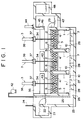
- Fig. 1 is a side sectional view showing an embodiment of a high speed upward flow filtration apparatus of the present invention;
- Fig. 2 is a side sectional view showing an enlarged left-hand portion of Fig. 1;
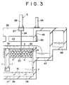
- Fig. 3 is a side sectional view showing a enlarged right-hand portion of Fig. 1;
- Fig. 4 is a plan view showing the embodiment of the high speed upward flow filtration apparatus of the present invention;
- Fig. 5 is a front sectional view showing the embodiment of the high speed upward flow filtration apparatus of the present invention;
- Fig. 6 is a side sectional view showing an enlarged part of the embodiment of the high speed upward flow filtration apparatus of the present invention;
- Fig. 7 is a front view of a fibrous lump;
- Fig. 8 is a sectional view of the fibrous lump;
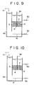
- Fig. 9 is a principle view showing a state where a filter layer is formed;
- Fig. 10 is a principle view showing a state where the filter layer is compressed;
- Fig. 11 is a principle view showing a state where a filtration is performed;
- Fig. 12 is a principle view showing a state where an upstream water level is increased;
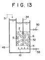
- Fig. 13 is a principle view showing a state where the fibrous lumps are cleaned; and
- Fig. 14 is a side sectional view showing a conventional filtration apparatus provided in a channel,
- Figs. 7 and 8 show a filtering
fibrous lump 5 comprising a crimpy fibrous lump, which is employed in an embodiment of the present invention. Thefibrous lump 5 has many bundledcrimpy fibers 8 formed by providing synthetic fibers of 20 to 200 denier with 2 to 10 crimps per inch (2,53 cm). The bundledcrimpy fibers 8 are wrung and bundled at the core portion thereof by abinding wire 9 such as a stiff synthetic fiber, a rigid plastic band, an aluminum wire or an anticorrosion metal wire. The bundledcrimpy fibers 8 are rounded to provide thefibrous lump 5 in the form of a substantial sphere having a diameter of 10 to 50 mm. - A fiber having a higher specific gravity than water, for example, a polyvinylidene chloride fiber is optimal for the synthetic fiber to constitute the
crimpy fiber 8. The synthetic fiber may be a polyvinyl chloride, a polyethylene fiber or other synthetic fibers. - Figs. 1 through 6 show an embodiment of a high speed upward flow filtration apparatus of the present invention. In the high speed upward flow filtration apparatus, raw water is introduced into a
feed water channel 21, and thereafter distributed by afeed water weir 22 to eachchannel 23. The water can be interrupted by an upstream verticalmovable isolation plate 24. The water fed from thefeed water channel 21 flows along anupstream weir 25 and is introduced into achannel bottom 27 via awater inlet 26. The water flows upwardly from thechannel bottom 27 throughplates 28, and is uniformly distributed to eachfilter layer 6. - A plurality of
fixed diaphragms 30 are provided between theupstream weir 25 of thechannel 23 and adownstream weir 29. Holding compressors for thefilter layer 6 are disposed between thefixed diaphragms 30. - The holding compressor comprises: four circumferential side plates 1 for receiving the fibrous lumps to form a vertical square cylinder; an upper perforated
panel 2 secured to anupper grid frame 32 which is rigidly fixed bybolts 31 on the upper portions of the respective circumferential side plates 1; a lower movable perforatedpanel 4 secured to alower grid frame 33 which is fitted into a portion surrounded by the respective circumferential side plates 1; and a vertical motion means 3 including afluid pressure cylinder 38 for vertically moving thelower grid frame 33 and the lower movable perforatedpanel 4. Theupper grid frame 32 is fixed by abolt 41 with respect to theupstream weir 25, thedownstream weir 29, thefixed diaphragm 30 and achannel side wall 36. - A
piston rod 34 of thevertical motion cylinder 38 passes through a guide cylinder 35 (Fig. 6). Theguide cylinder 35 is disposed at an intermediate portion of theupper grid frame 32. The lower end of thepiston rod 34 is coupled with thelower grid frame 33. Thecylinder 38 is secured to aframe 37 which is fixed on the respectivechannel side walls 36. Arubber packing 40 is disposed between the lower end surface of the respective circumferential side plates 1 and upper surfaces ofpedestals 39. Thepedestals 39 are disposed at lower positions of theupstream weir 25, thedownstream weir 29, thefixed diaphragm 30, and thechannel side wall 36. - A large number of
fibrous lumps 5 are filled into a chamber defined by the upperperforated panel 2, the lower movable perforatedpanel 4, and the four circumferential side plates 1. The lower movable perforatedpanel 4 is raised to form thefilter layer 6, and further raised to compress thefibrous lumps 5 to form the uniform anddense filter layer 6. - Unfiltered
water supply chambers 7 communicating with thechannel bottom 27 are provided under the respective lower movable perforatedpanels 4. Fibrouslump cleaning diffusers 10 comprising an air injection pipe with many injection holes are disposed at the lower portion of the unfilteredwater supply chambers 7. The fibrouslump cleaning diffusers 10 are connected to anair blower 42. A plurality of distributingweirs 43 are provided for thechannel side walls 36 at a higher position than that of thedownstream weir 29. Adownstream isolation plate 46 is disposed above thedownstream weir 29, and is vertically movable by apiston rod 45 of avertical motion cylinder 44. - A
channel 47 for filtered water is arranged downstream thedownstream weir 29, and acatch drain 48 is arranged adjacent to thechannel 47. - The unfiltered water in the
feed water channel 21 is introduced into thechannel 23 by thefeed water weir 22. The water flows along theupstream weir 25, and is introduced into thechannel bottom 27 via thewater inlet 26. The water streams upwardly from thechannel bottom 27, and is uniformly distributed toward therespective filter layers 6 by theplates 28. - The lower movable
perforated panel 4 is raised by thevertical motion cylinder 38 to hold thefilter layer 6 comprising manyfibrous lumps 5 between the upperperforated panel 2 and the lower movableperforated panel 4. The lower movableperforated panel 4 is further raised to compress thefibrous lumps 5 and to eliminate air gaps between thefibrous lumps 5, so that a dense anduniform filter layer 6 is formed. The upward flow of the raw water (unfiltered water) rising in the unfilteredwater supply chamber 7 is filtered by passing through thefilter layer 6. The filtered water flows over thedownstream weir 29, and is discharged via the filteredwater channel 47. - As the water is filtered, fine solid materials in the upward flow progressively adhere to the
filter layer 6 in the order from the lower portion to the upper portion thereof Accordingly, with progressing filtration, the flow resistance is increased so that the water level upstream thewater inlet 26 is increased. - After filtration for a certain time, the
downstream isolation plate 46 is closed so that the water level above therespective filter layers 6 rises and the filtered water can pass through the distributingweir 43. In this case, the lower movableperforated panel 4 is lowered to form a cleaning chamber 52 (Fig 13) between the lower movableperforated panel 4 and the upperperforated panel 2. - Next, air is injected from the fibrous
lump cleaning diffuser 10 disposed under the unfilteredwater supply chamber 7 to cause an upward flow of water mixed with air. Consequently, thefibrous lumps 5 in the cleaning chamber are agitated in water and cleaned, and the cleaning drain is discharged from the distributingweir 43 to thecatch drain 48. - After completion of cleaning the
fibrous lumps 5, the lower movableperforated panel 4 is raised to form again a dense anduniform filter layer 6. Thereafter, air injection from the fibrouslump cleaning diffuser 10 is stopped. Further, thedownstream isolation plate 46 is opened and filtration can be started again. - It is preferred to use
fibrous lumps 5 having a diameter of about 40 mm, which is formed of polyvinylidene crimpy fibers with a true specific gravity more than 1. In this case, if thefilter layer 6 is formed without compressing thefibrous lumps 5, thefilter layer 6 has a void ratio of 93%. Thus, filtration efficiency is low due to air gaps between thefibrous lumps 5, and air gaps between thefibrous lumps 5 and the circumferential side plates 1. - If the
fibrous lumps 5 are compressed to reduce the void ratio to about 90%, it is possible to eliminate unnecessary air gaps and to form a dense anduniform filter layer 6. As a result, a high performance filtration can be performed. - During cleaning, the
fibrous lumps 5 can recover their original sphereical form as soon as the compression force is released. Accordingly, thefibrous lumps 5 have a form suitable for cleaning, and can be efficiently cleaned. - For example, if the
fibrous lumps 5 are filled in at a density of 75 kg/m² and thefilter layer 6 has a thickness of about 50 cm, filtration can be performed at a rate of 50 to 100 m³/m²·h. - Referring now to the principle views as shown in Figs. 9 through 13, a description will be given of a cleaning operation of the high speed upward flow filtration apparatus of the present invention.
- As shown in Fig. 9, when the lower movable
perforated panel 4 is raised, thefibrous lumps 5 are held to form thefilter layer 6 between the upperperforated panel 2 and the lower movableperforated panel 4. - If the lower movable
perforated panel 4 is further raised, as shown in Fig. 10, thefibrous lumps 5 are compressed between the upper and lower panels and deformed. Consequently, the compression allows to eliminate air gaps between thefibrous lumps 5 with each other and air gaps between thefibrous lumps 5 and the circumferential side plates 1. Thus, a dense anduniform filter layer 6 can be formed. - Next, when a filtered
water exhaust valve 50 connected to awater tank 49 above thefilter layer 6 is opened, theraw water 51 fed in thewater tank 49 upwardly passes through thefilter layer 6. Hence, the filtration is started as shown in Fig. 11. - During filtration, fine solid materials adhere to the fibrous lumps 5. Accordingly, the pressure loss of the
filter layer 6 is increased so that the upstream water level is raised as shown in Fig. 12. - During further filtration, the filtration performance is reduced and it is necessary to clean the fibrous lumps 5. Thus, as shown in Fig. 13, the filtered
water exhaust valve 50 is closed to raise the water level above thefilter layer 6 so that the filtered water can be discharged. At this time, the lower movableperforated panel 4 is lowered to define thecleaning chamber 52 between the upperperforated panel 2 and the lower movableperforated panel 4. Furthermore, anair supply valve 53 is opened to allow the fibrouslump cleaning diffuser 10 to inject air to cause the upward flow of water mixed with air. The upward flow can agitate thefibrous lumps 5 in thecleaning chamber 52 to float, and improves the cleaning of the fibrous lumps 5. - After completion of cleaning, as shown in Figs. 9 and 10, the lower movable
perforated panel 4 is progressively raised to form again thefilter layer 6. Thereafter, theair supply valve 53 is closed to stop air injection from the fibrouslump cleaning diffuser 10. Theraw water 51 can continuously flow and can be used as back wash water for cleaning.
Claims (5)
- A high speed upward flow filtration apparatus, comprising:
an inlet (26) for introducing feed water into said apparatus;
an outlet for discharging filtered water from said apparatus;
a drain (48) for discharging unfiltered water from said apparatus;
a first perforated panel (2) immovably mounted within said apparatus;
a second perforated panel (4) movably mounted within said apparatus and spaced below said first perforated panel (2),
means (3) for selectively moving said movably mounted second perforated panel (4) toward and away from said first perforated panel (2), with parts (38) of said means (3) being located above said first perforated panel (2) and parts (34) of said means (3) extending downwardly,
a plurality of fibrous lumps (5) disposed between said first and second perforated panels, each fibrous lump (5) comprising a generally spherical bundle formed by a plurality of crimpy fibers (8) secured to one another at a core portion thereof by a binding wire means (9).
means (10) for selectively agitating said feed water,
isolation plate means (46) for closing said outlet and
distribution weir means (43) for directing feed water to said drain (48) whereby
said first and second perforated panels (2, 4) are spaced apart from one another a first predetermined distance when the apparatus is in a filtration mode of operation;
said first and second perforated panels are spaced apart from one another a second predetermined distance to form a cleaning chamber (52) when the apparatus is in a back wash mode, said second predetermined distance being greater than said first predetermined distance,
whereby cleaning of said fibrous lumps (5) is accomplished by closing said outlet, moving said movably mounted second perforated panel (4) away from said immovably mounted first panel (2) to create said cleaning chamber (52) so that said fibrous lumps (5) may become widely spaced apart from one another, maintaining said inlet open, and activating said means (10) for agitating said feed water so that the level of the feed water within said apparatus rises upon closing of said outlet and so that said feed water at said higher level is directed by said distribution weir means (43) to said drain, (48) said agitation of said feed water serving to clean said spaced apart fibrous lumps (5) within said cleaning chamber (52); and
whereby after said fibrous lumps have been cleaned, said second perforated panel (4) is returned to said first predetermined distance from said first perforated panel and said outlet is opened, said opening of said outlet being effective to lower the level of feed water within said apparatus and to thereby divert said feed water from said drain to said outlet - The apparatus of claim 1, wherein said inlet further includes a feed water channel (21) and a feed water weir (22) over which water in said feed water channel must flow to enter said filtration means.
- The apparatus of claim 2, further comprising an upstream weir (25) having a submerged lower end under which feed water that has flowed over said feed water weir (22) must flow to reach said filtration means.
- The apparatus of claim 1 to 3, wherein said outlet of said apparatus leads to a filtered water channel (47), and comprises a downstream weir (29) over which filtered water must flow to reach said filtered water channel (47).
- The apparatus of claim 1 to 4, wherein said means for selectively agitating said feed water includes a fibrous lump cleaning diffuser (10) in the form of an air injection pipe having a plurality of injection holes formed therein, and an air blower (42) for selectively introducing air into said pipe.
Priority Applications (5)
| Application Number | Priority Date | Filing Date | Title |
|---|---|---|---|
| JP29775691A JP3734227B2 (en) | 1991-10-18 | 1991-10-18 | Upflow type high-speed filter |
| US07/880,108 US5248415A (en) | 1991-10-18 | 1992-05-06 | High speed upward flow filtration apparatus |
| EP92122098A EP0608441B1 (en) | 1991-10-18 | 1992-12-29 | High speed upward flow filtration apparatus |
| CA002086349A CA2086349C (en) | 1991-10-18 | 1992-12-29 | High speed upward flow filtration apparatus |
| DE1992611008 DE69211008T2 (en) | 1992-12-29 | 1992-12-29 | High speed filtration device for ascending flow |
Applications Claiming Priority (3)
| Application Number | Priority Date | Filing Date | Title |
|---|---|---|---|
| JP29775691A JP3734227B2 (en) | 1991-10-18 | 1991-10-18 | Upflow type high-speed filter |
| EP92122098A EP0608441B1 (en) | 1991-10-18 | 1992-12-29 | High speed upward flow filtration apparatus |
| CA002086349A CA2086349C (en) | 1991-10-18 | 1992-12-29 | High speed upward flow filtration apparatus |
Publications (2)
| Publication Number | Publication Date |
|---|---|
| EP0608441A1 EP0608441A1 (en) | 1994-08-03 |
| EP0608441B1 true EP0608441B1 (en) | 1996-05-22 |
Family
ID=27169303
Family Applications (1)
| Application Number | Title | Priority Date | Filing Date |
|---|---|---|---|
| EP92122098A Expired - Lifetime EP0608441B1 (en) | 1991-10-18 | 1992-12-29 | High speed upward flow filtration apparatus |
Country Status (4)
| Country | Link |
|---|---|
| US (1) | US5248415A (en) |
| EP (1) | EP0608441B1 (en) |
| JP (1) | JP3734227B2 (en) |
| CA (1) | CA2086349C (en) |
Families Citing this family (44)
| Publication number | Priority date | Publication date | Assignee | Title |
|---|---|---|---|---|
| US5558763A (en) * | 1993-06-24 | 1996-09-24 | Hitachi Plant Engineering & Construction Co., Ltd. | Sewage treatment system with air jetting means |
| JP2000511823A (en) * | 1996-12-10 | 2000-09-12 | シュライバー・コーポレイション | High-speed filtration system |
| US20030111431A1 (en) * | 1996-12-10 | 2003-06-19 | Schreiber Corporation | High rate filtration system |
| IL128172A (en) * | 1999-01-21 | 2001-12-23 | Sinomed Ltd | Deep media filter |
| US6158386A (en) * | 1999-08-18 | 2000-12-12 | Aquatic Engineers, Inc. | Fluid treatment systems |
| FR2798865B1 (en) * | 1999-09-23 | 2001-11-16 | Degremont | IMPROVEMENTS ON GRANULAR MATERIAL BED FILTERS, ESPECIALLY FOR WATER TREATMENT |
| WO2002081050A1 (en) * | 2001-04-04 | 2002-10-17 | Ngk Insulators, Ltd. | Rain water treating device in combined sewage, and backwashing method therefor |
| EP1599269B1 (en) * | 2003-01-29 | 2009-11-18 | Wwetco, Llc | Apparatus and method for filtering fluids |
| US7799235B2 (en) | 2004-07-23 | 2010-09-21 | Contech Stormwater Solutions, Inc. | Fluid filter system and related method |
| US7425274B1 (en) * | 2004-12-09 | 2008-09-16 | Leon Helfet | Aquarium filter unit |
| JP4532297B2 (en) * | 2005-01-24 | 2010-08-25 | オルガノ株式会社 | Filtration apparatus and filtration method |
| US7758750B2 (en) * | 2005-08-19 | 2010-07-20 | Rg Delaware, Inc. | Flume for a filter system including at least one filter having a filter bed that is periodically washed with liquid, gas or a combination thereof |
| US7628913B2 (en) * | 2005-10-05 | 2009-12-08 | J.W. Pet Company, Inc. | Aquarium filter cartridge and filtration system |
| US8110099B2 (en) * | 2007-05-09 | 2012-02-07 | Contech Stormwater Solutions Inc. | Stormwater filter assembly |
| US8287726B2 (en) | 2007-08-15 | 2012-10-16 | Monteco Ltd | Filter for removing sediment from water |
| US20110147321A1 (en) * | 2008-08-29 | 2011-06-23 | Nir Oz | Filter with adjustable porosity |
| CN101837208A (en) * | 2010-03-29 | 2010-09-22 | 上海凡清环境工程有限公司 | Method and device for filtering upward-flow fiber bundle |
| CN102343166A (en) * | 2010-07-23 | 2012-02-08 | 上海凡清环境工程有限公司 | Liquid surface strengthened scrubbing method for filtering material layer of filter |
| JP4982612B1 (en) | 2011-02-02 | 2012-07-25 | メタウォーター株式会社 | Filtration system |
| ES2618911T3 (en) * | 2011-03-25 | 2017-06-22 | Doosan Heavy Industries & Construction Co., Ltd. | Dissolved air flotation pretreatment apparatus |
| EP2510992B1 (en) * | 2011-04-11 | 2017-09-27 | Dari GmbH | Filter material for cleaning a fluid |
| US20130001161A1 (en) * | 2011-06-28 | 2013-01-03 | Mark Boner | Biological Treatment and Compressed Media Filter Apparatus and Method |
| US9718004B2 (en) * | 2011-10-03 | 2017-08-01 | Ishigaki Company Limited | Filter medium layer and filter device provided with same |
| CN103055588A (en) * | 2011-10-20 | 2013-04-24 | 上海凡清环境工程有限公司 | Mechanical adjusting filter system |
| US9169580B2 (en) * | 2011-11-22 | 2015-10-27 | Tipper Tie, Inc. | Apparatus for forming fiber balls with clippers and related methods |
| US9403108B2 (en) * | 2012-01-12 | 2016-08-02 | Global Splash, Inc. | Filtration operator |
| US9034188B2 (en) * | 2013-01-23 | 2015-05-19 | Pei-Yuan Lee | Cleaning structure for floating oil and substance on water surface |
| US20140332458A1 (en) * | 2013-05-08 | 2014-11-13 | Filtrasonics Llc | Regenerative fluid filtration micro-cell |
| JP6156993B2 (en) * | 2013-08-02 | 2017-07-05 | 株式会社industria | Filter device and fluid purification system |
| CN104436776A (en) * | 2014-11-11 | 2015-03-25 | 江苏华达环境工程有限公司 | Fiber filter |
| US20160297688A1 (en) | 2015-04-08 | 2016-10-13 | Amcol International Corporation | System and method for removing solids and hydrocarbons from water |
| US10744426B2 (en) * | 2015-12-31 | 2020-08-18 | Crystaphase Products, Inc. | Structured elements and methods of use |
| US10029922B2 (en) * | 2016-02-12 | 2018-07-24 | Denny Hastings Flp 14 | Transportable multi-chamber water filtration systems |
| US10054140B2 (en) | 2016-02-12 | 2018-08-21 | Crystaphase Products, Inc. | Use of treating elements to facilitate flow in vessels |
| WO2017161381A1 (en) * | 2016-03-18 | 2017-09-21 | Schreiber, Llc | Improved methods for cleaning filtration system media |
| US10953352B2 (en) | 2017-05-19 | 2021-03-23 | Baleen Process Solutions | Fluid treatment system and method of use utilizing a membrane |
| US10913667B2 (en) | 2017-12-08 | 2021-02-09 | Westech Engineering, Inc. | Multi-media clarification systems and methods |
| JP7309490B2 (en) * | 2019-07-09 | 2023-07-18 | 高砂熱学工業株式会社 | Flushing water treatment filter, flushing water treatment filter manufacturing method, flushing water treatment filter device, flushing water treatment filter system, and flushing water treatment method |
| KR20220105677A (en) | 2019-12-20 | 2022-07-27 | 크라이스타페이즈 프로덕츠, 인크. | Gas Resaturation to Liquid Feed Stream |
| JP2023541252A (en) | 2020-09-09 | 2023-09-29 | クリスタフェーズ・プロダクツ・インコーポレーテッド | Process vessel entry zone |
| US12589336B1 (en) * | 2022-01-18 | 2026-03-31 | Theodore A. Kuepper | Lightweight fibrous media (LFM) filter |
| US11583788B1 (en) * | 2022-01-18 | 2023-02-21 | Theodore A. Kuepper | Lightweight fibrous media (LFM) filter |
| WO2024059460A1 (en) * | 2022-09-14 | 2024-03-21 | Specialty Minerals (Michigan) Inc. | Filtration systems and methods of operation |
| KR102794771B1 (en) * | 2024-11-25 | 2025-04-15 | 주식회사 포우천개발 | Multipurpose manhole fall prevention device |
Family Cites Families (6)
| Publication number | Priority date | Publication date | Assignee | Title |
|---|---|---|---|---|
| US4139473A (en) * | 1977-09-12 | 1979-02-13 | Alldredge Robert L | Filter |
| US4246119A (en) * | 1979-02-12 | 1981-01-20 | Alldredge Robert L | Liquid sand filter |
| GB2198365A (en) * | 1986-08-04 | 1988-06-15 | Howden James & Co Ltd | Filter |
| JP2700885B2 (en) * | 1987-09-26 | 1998-01-21 | 株式会社林原生物化学研究所 | Filter aid and method for producing the same |
| JPH01249113A (en) * | 1988-03-30 | 1989-10-04 | Yokohamashi | Horizontal filter bed type low pressure drop upflow filtration device |
| GB2239192A (en) * | 1989-12-19 | 1991-06-26 | Edward Andrew Seymour | Filter bed |
-
1991
- 1991-10-18 JP JP29775691A patent/JP3734227B2/en not_active Expired - Lifetime
-
1992
- 1992-05-06 US US07/880,108 patent/US5248415A/en not_active Expired - Lifetime
- 1992-12-29 EP EP92122098A patent/EP0608441B1/en not_active Expired - Lifetime
- 1992-12-29 CA CA002086349A patent/CA2086349C/en not_active Expired - Lifetime
Also Published As
| Publication number | Publication date |
|---|---|
| CA2086349A1 (en) | 1994-06-30 |
| US5248415A (en) | 1993-09-28 |
| EP0608441A1 (en) | 1994-08-03 |
| JP3734227B2 (en) | 2006-01-11 |
| CA2086349C (en) | 1997-03-04 |
| JPH0679107A (en) | 1994-03-22 |
Similar Documents
| Publication | Publication Date | Title |
|---|---|---|
| US5248415A (en) | High speed upward flow filtration apparatus | |
| US4885083A (en) | Single chamber filter vessel | |
| EP0280052B1 (en) | Method of and apparatus for filtering a medium | |
| US5454959A (en) | Moving bed filters | |
| US5401405A (en) | Combined air/water backwash in a travelling bridge filter | |
| RU2455049C2 (en) | Method and device for cleaning filters with loose packing | |
| US4486205A (en) | Powdery dust separating apparatus in dust collector | |
| CA2514929C (en) | Apparatus and method for filtering fluids | |
| CA2037888A1 (en) | Backwash method and apparatus | |
| US3840117A (en) | Underdrain structure for waste effluent filter and method of using same | |
| US4196079A (en) | Pleated filter underdrain, method and apparatus | |
| US5730886A (en) | Continuous self-cleaning filtration unit | |
| US4515691A (en) | Filtration apparatus | |
| US4308141A (en) | Modular filter system | |
| GB1564978A (en) | Process and apparatus for cleaning particulate filters | |
| US4524139A (en) | Process for the compressive regeneration of flexible, porous materials | |
| KR102348752B1 (en) | non-point source contaminant reduction | |
| US3598235A (en) | Process and equipment for the purification of liquids by filtration | |
| IE52957B1 (en) | Process and apparatus for extracting ions from a clear liquid containing materials in suspension by contact with an exchange substance | |
| JPH06170117A (en) | Underlying water collecting module and system for filtering device | |
| US4964987A (en) | Cross flow filter apparatus | |
| US3497063A (en) | Method of and apparatus for filtering | |
| CA2110720A1 (en) | Filtration process and apparatus | |
| US5009776A (en) | Filter system | |
| CN109502816A (en) | A kind of Zhi Xian factory sewage disposal system and method |
Legal Events
| Date | Code | Title | Description |
|---|---|---|---|
| PUAI | Public reference made under article 153(3) epc to a published international application that has entered the european phase |
Free format text: ORIGINAL CODE: 0009012 |
|
| 17P | Request for examination filed |
Effective date: 19930913 |
|
| AK | Designated contracting states |
Kind code of ref document: A1 Designated state(s): DE FR GB SE |
|
| 17Q | First examination report despatched |
Effective date: 19941223 |
|
| RAP1 | Party data changed (applicant data changed or rights of an application transferred) |
Owner name: MITSUI MINING COMPANY, LIMITED |
|
| GRAH | Despatch of communication of intention to grant a patent |
Free format text: ORIGINAL CODE: EPIDOS IGRA |
|
| GRAA | (expected) grant |
Free format text: ORIGINAL CODE: 0009210 |
|
| AK | Designated contracting states |
Kind code of ref document: B1 Designated state(s): DE FR GB SE |
|
| ET | Fr: translation filed | ||
| REF | Corresponds to: |
Ref document number: 69211008 Country of ref document: DE Date of ref document: 19960627 |
|
| PLBE | No opposition filed within time limit |
Free format text: ORIGINAL CODE: 0009261 |
|
| STAA | Information on the status of an ep patent application or granted ep patent |
Free format text: STATUS: NO OPPOSITION FILED WITHIN TIME LIMIT |
|
| 26N | No opposition filed | ||
| REG | Reference to a national code |
Ref country code: GB Ref legal event code: IF02 |
|
| REG | Reference to a national code |
Ref country code: GB Ref legal event code: 732E |
|
| REG | Reference to a national code |
Ref country code: FR Ref legal event code: CA Ref country code: FR Ref legal event code: TP |
|
| REG | Reference to a national code |
Ref country code: GB Ref legal event code: 732E Free format text: REGISTERED BETWEEN 20090709 AND 20090715 |
|
| REG | Reference to a national code |
Ref country code: FR Ref legal event code: TP |
|
| PGFP | Annual fee paid to national office [announced via postgrant information from national office to epo] |
Ref country code: GB Payment date: 20101229 Year of fee payment: 19 |
|
| PGFP | Annual fee paid to national office [announced via postgrant information from national office to epo] |
Ref country code: FR Payment date: 20111220 Year of fee payment: 20 Ref country code: SE Payment date: 20111221 Year of fee payment: 20 |
|
| PGFP | Annual fee paid to national office [announced via postgrant information from national office to epo] |
Ref country code: DE Payment date: 20120123 Year of fee payment: 20 |
|
| REG | Reference to a national code |
Ref country code: DE Ref legal event code: R071 Ref document number: 69211008 Country of ref document: DE |
|
| REG | Reference to a national code |
Ref country code: GB Ref legal event code: PE20 Expiry date: 20121228 |
|
| REG | Reference to a national code |
Ref country code: SE Ref legal event code: EUG |
|
| PG25 | Lapsed in a contracting state [announced via postgrant information from national office to epo] |
Ref country code: GB Free format text: LAPSE BECAUSE OF EXPIRATION OF PROTECTION Effective date: 20121228 |
|
| PG25 | Lapsed in a contracting state [announced via postgrant information from national office to epo] |
Ref country code: DE Free format text: LAPSE BECAUSE OF EXPIRATION OF PROTECTION Effective date: 20130101 |