EP0608122A2 - Sensor for combustible gases - Google Patents
Sensor for combustible gases Download PDFInfo
- Publication number
- EP0608122A2 EP0608122A2 EP94300386A EP94300386A EP0608122A2 EP 0608122 A2 EP0608122 A2 EP 0608122A2 EP 94300386 A EP94300386 A EP 94300386A EP 94300386 A EP94300386 A EP 94300386A EP 0608122 A2 EP0608122 A2 EP 0608122A2
- Authority
- EP
- European Patent Office
- Prior art keywords
- elements
- temperature
- chamber
- sensor according
- sensor
- Prior art date
- Legal status (The legal status is an assumption and is not a legal conclusion. Google has not performed a legal analysis and makes no representation as to the accuracy of the status listed.)
- Granted
Links
- 239000007789 gas Substances 0.000 title claims description 54
- 239000003054 catalyst Substances 0.000 claims abstract description 23
- 239000000919 ceramic Substances 0.000 claims abstract description 12
- 239000000758 substrate Substances 0.000 claims description 11
- 238000002485 combustion reaction Methods 0.000 claims description 7
- 238000005524 ceramic coating Methods 0.000 claims description 2
- 230000003197 catalytic effect Effects 0.000 abstract description 11
- 239000000203 mixture Substances 0.000 abstract description 9
- 239000011521 glass Substances 0.000 abstract description 7
- 230000008859 change Effects 0.000 abstract description 4
- BASFCYQUMIYNBI-UHFFFAOYSA-N platinum Chemical compound [Pt] BASFCYQUMIYNBI-UHFFFAOYSA-N 0.000 description 22
- MCMNRKCIXSYSNV-UHFFFAOYSA-N Zirconium dioxide Chemical compound O=[Zr]=O MCMNRKCIXSYSNV-UHFFFAOYSA-N 0.000 description 12
- 229910052697 platinum Inorganic materials 0.000 description 10
- 239000000463 material Substances 0.000 description 8
- 230000035945 sensitivity Effects 0.000 description 7
- PNEYBMLMFCGWSK-UHFFFAOYSA-N aluminium oxide Inorganic materials [O-2].[O-2].[O-2].[Al+3].[Al+3] PNEYBMLMFCGWSK-UHFFFAOYSA-N 0.000 description 5
- 230000000694 effects Effects 0.000 description 4
- 238000005516 engineering process Methods 0.000 description 4
- 238000006243 chemical reaction Methods 0.000 description 3
- 238000012544 monitoring process Methods 0.000 description 3
- 239000010935 stainless steel Substances 0.000 description 3
- 229910001220 stainless steel Inorganic materials 0.000 description 3
- 239000011248 coating agent Substances 0.000 description 2
- 238000000576 coating method Methods 0.000 description 2
- 230000001419 dependent effect Effects 0.000 description 2
- 238000009792 diffusion process Methods 0.000 description 2
- 238000010438 heat treatment Methods 0.000 description 2
- 238000000034 method Methods 0.000 description 2
- 230000003647 oxidation Effects 0.000 description 2
- 238000007254 oxidation reaction Methods 0.000 description 2
- 239000008188 pellet Substances 0.000 description 2
- 239000011148 porous material Substances 0.000 description 2
- 239000000843 powder Substances 0.000 description 2
- 238000000926 separation method Methods 0.000 description 2
- 239000002002 slurry Substances 0.000 description 2
- 239000010409 thin film Substances 0.000 description 2
- VYPSYNLAJGMNEJ-UHFFFAOYSA-N Silicium dioxide Chemical compound O=[Si]=O VYPSYNLAJGMNEJ-UHFFFAOYSA-N 0.000 description 1
- 239000002253 acid Substances 0.000 description 1
- 239000000956 alloy Substances 0.000 description 1
- 229910045601 alloy Inorganic materials 0.000 description 1
- QVGXLLKOCUKJST-UHFFFAOYSA-N atomic oxygen Chemical compound [O] QVGXLLKOCUKJST-UHFFFAOYSA-N 0.000 description 1
- 230000015572 biosynthetic process Effects 0.000 description 1
- 230000000903 blocking effect Effects 0.000 description 1
- 238000007084 catalytic combustion reaction Methods 0.000 description 1
- 238000006555 catalytic reaction Methods 0.000 description 1
- 229910010293 ceramic material Inorganic materials 0.000 description 1
- 150000001875 compounds Chemical class 0.000 description 1
- 238000010276 construction Methods 0.000 description 1
- 238000000354 decomposition reaction Methods 0.000 description 1
- 239000010432 diamond Substances 0.000 description 1
- 229910003460 diamond Inorganic materials 0.000 description 1
- DCSRPHQBFSYJNN-UHFFFAOYSA-L disodium 4-[(2-arsonophenyl)diazenyl]-3-hydroxynaphthalene-2,7-disulfonate Chemical compound [Na+].[Na+].Oc1c(N=Nc2ccccc2[As](O)(O)=O)c2ccc(cc2cc1S([O-])(=O)=O)S([O-])(=O)=O DCSRPHQBFSYJNN-UHFFFAOYSA-L 0.000 description 1
- 238000009713 electroplating Methods 0.000 description 1
- 239000010408 film Substances 0.000 description 1
- 239000005350 fused silica glass Substances 0.000 description 1
- 231100001261 hazardous Toxicity 0.000 description 1
- 230000006872 improvement Effects 0.000 description 1
- 238000004519 manufacturing process Methods 0.000 description 1
- 239000011159 matrix material Substances 0.000 description 1
- 239000001301 oxygen Substances 0.000 description 1
- 229910052760 oxygen Inorganic materials 0.000 description 1
- 229910052763 palladium Inorganic materials 0.000 description 1
- 239000010970 precious metal Substances 0.000 description 1
- 230000008569 process Effects 0.000 description 1
- 230000001681 protective effect Effects 0.000 description 1
- 229910052703 rhodium Inorganic materials 0.000 description 1
- 238000007650 screen-printing Methods 0.000 description 1
- 239000005394 sealing glass Substances 0.000 description 1
- 239000004065 semiconductor Substances 0.000 description 1
- 238000007493 shaping process Methods 0.000 description 1
- 238000005245 sintering Methods 0.000 description 1
- 229910002076 stabilized zirconia Inorganic materials 0.000 description 1
- 230000005676 thermoelectric effect Effects 0.000 description 1
- XLYOFNOQVPJJNP-UHFFFAOYSA-N water Substances O XLYOFNOQVPJJNP-UHFFFAOYSA-N 0.000 description 1
Images




Classifications
-
- G—PHYSICS
- G01—MEASURING; TESTING
- G01N—INVESTIGATING OR ANALYSING MATERIALS BY DETERMINING THEIR CHEMICAL OR PHYSICAL PROPERTIES
- G01N27/00—Investigating or analysing materials by the use of electric, electrochemical, or magnetic means
- G01N27/02—Investigating or analysing materials by the use of electric, electrochemical, or magnetic means by investigating impedance
- G01N27/04—Investigating or analysing materials by the use of electric, electrochemical, or magnetic means by investigating impedance by investigating resistance
- G01N27/14—Investigating or analysing materials by the use of electric, electrochemical, or magnetic means by investigating impedance by investigating resistance of an electrically-heated body in dependence upon change of temperature
- G01N27/16—Investigating or analysing materials by the use of electric, electrochemical, or magnetic means by investigating impedance by investigating resistance of an electrically-heated body in dependence upon change of temperature caused by burning or catalytic oxidation of surrounding material to be tested, e.g. of gas
Definitions
- the present invention relates to a sensor, of the catalytic calorimeter type, for sensing the concentration of combustible gases in a gas mixture.
- the platinum coil heats the catalyst to a suitable temperature at which the oxidation of the combustible gas is induced on the surface of the catalyst.
- the heat generated will be conducted to the coil and raise its temperature and hence alter its resistance.
- Acoil in a pellet with no catalyst is used as a reference.
- the present invention has as an object the provision of a catalytic calori meterfor sensing combustible gases which has increased sensitivity as compared to the known devices mentioned above.
- the present invention provides a sensor for a combustible gas comprising:
- the heater for the chamber can be independently designed to provide proper heating of the chamber sensors and gas.
- the sensor is heated to be at the required reaction temperature and the gas is also at that temperature as it reaches the sensor.
- the sensor is positioned within a heated vessel at a location of very small or zero temperature gradient.
- the invention comprises four identical temperature sensitive elements fabricated on a ceramic substrate symmetrically arranged around a central point. Alternate ones of the elements are associated with a catalyst which then become the sensing elements and the others are reference elements.
- the catalyst is preferably disposed in a porous substrate covering the elements. The change in the value of the resistance of the elements under the reactive elements due to the catalytic oxidation of the combustible gas on the surface of the catalyst raising the local temperature, is used to monitor the concentration of the combustible gas.
- temperature sensitive and radially extended elements are formed symmetrically on a thin substrate by a suitable process such as thick or thin film technology.
- the temperature sensitive element could be a material such as platinum, a semi-conductor (thermistor) suitably manufactured or a material such as diamond powder thin film thermistor suitably deposited which displays temperature dependent behaviour.
- the substrate 10, shown in Fig. 1 is made of a material with poor heat conductivity properties such as a suitable ceramic, and has to be thin so that it can be positioned inside the reactor under a region of constant temperature where it will suffer no temperature gradients.
- a thin section reduces heat exchange to the surroundings and between the separate elements. This heat exchange between elements is further reduced by the choice of substrate material and by the inclusion of thin slots 2 between elements so as to break the heat conductive paths.
- the slots 2 also allow the gas from under the element to move to the top of the element encouraging proper gas exchange.
- Figs. 2(a) and (b) show two suitable designs as examples, comprising the track of the resistive elements 6 and pads 7 to which the lead wires are connected.
- the elements are as near identical as possible in their electrical characteristics (resistance value and sensitivity to temperature) and in their physical form, so as to reduce the common mode effects such as those due to the thermal conductivity of the background non combusting gases, the effect of flow variation, changes in the ambient temperature and in the temperature of the sample gas and so on.
- the four elements are covered with a very thin glass layer which electrically insulates them from any overlays; but is thin enough to allow the heat to conduct to the elements.
- Each of the four elements is then covered with a uniform porous ceramic coating; but only in the ceramic above two diametrically opposed elements is the catalyst dispersed.
- two diametrically opposed elements can be sealed with glass or any other inert coating whilst the other two treated as described earlier and doped with a catalyst.
- the catalyst could be one of the precious metals or their oxides (Pt, Rh, lr, Pd..) or any other suitable catalyst chosen usually to suit the combustible gas required to be monitored.
- substrate 10 is mounted inside a protective shroud assembly 11 which is seated by way of ledge 16, on a ceramic table 17 and fits onto the end assembly 15.
- the table 17 sits on the end assembly 15 and centrally over a four bore ceramic unit 13.
- Wires 12 to the four element sensor are hermetically sealed within the four bore ceramic unit 13 which is itself hermetically sealed at surface 14 to the metallic end assembly 15.
- the total assembly of the sensor device including the parts shown in Fig. 3 is shown in Fig. 4.
- the sensor head unit is inserted into a suitably designed reactor vessel 25 and screwed gas tight through an appropriate seal 26 at the end.
- the reactor vessel is spatially heated on the outside by an appropriate heater 27 that surrounds tightly the reactor vessel.
- a temperature sensor such as a platinum resistance thermometer 28, and appropriate electronics the temperature inside the reactor is controlled.
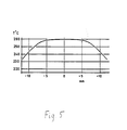
- the temperature sensor position within the body is chosen carefully so that the sensor position is in the flat portion of the temperature profile along the axis of the reactor as shown in Fig. 5, which shows temperature plotted against distance from the sensor plate.
- Fig. 5 shows temperature plotted against distance from the sensor plate.
- the sensor element 10 is positioned with its plane perpendicular to the axis of the reactor and at a point where the temperature gradient is nearly flat. This positioning and the fact that the element is very thin ensures very constant ambient temperature conditions around the sensor, and hence allows the sensor to resolve the very small temperature changes on its catalytic surface.
- the gas mixture is admitted to one end of the reactor indicated by arrow 29 and distributed round the inside of the body of the reactor, and the outside shroud of the element, so that it gradually reaches the inner temperature of the reactor, and at the point of low temperature gradient the gas has attained exactly the temperature of that region.
- the incoming gas, at that point, is induced to turn in partially towards the element as shown in Fig. 6 by the shaping 42 of the inner side of the shroud and the top inner end 43 of the vessel 25.
- a combination of flow and diffusion causes the gas to reach the surface of the element where the catalytic reaction takes place.
- the products of combustion 40 join some of the incoming gas and leave the vessel through outlet pipe 30. This is encouraged by the shape of the top part of the inner side of the reactor vessel 43.
- the incoming gas should reach the same temperature of the elements and that the sensor disc should be positioned at the flat part of the temperature gradient inside the vessel. It is also important that the inside and particularly the top part of the reactor vessel is designed so that the element is not exposed to direct fast gas flow. The element should receive only very low direct flow and the arrival of gas at this sensor element should be mainly due to diffusion. The main part of the gas flow induces the gases at the surface of the element to be sucked to the outlet thereby removing the products of combustion and enabling fresh gas to arrive at the surface of the element.
- the four element sensor can be connected as a bridge circuit (DC or AC) with the non catalytic elements acting as reference units and the catalysed elements as combustible gas sensitive units.
- the bridge is balanced in the presence of a non-combustible gas such as air, and calibrated by admitting a combustible/air gas mixture of known concentration.
- a non-combustible gas such as air
- appropriate electronic circuitry and display the unbalance in the bridge due to the catalytic combustion of the combustible gas altering the resistance of the elements underneath it due to the resultant heat generated may be related to the concentration of the combustible gas.
- the choice of gas necessitates a choice of appropriate catalyst and appropriate operating temperature.
- Athin (0.2mm) stabilized zirconia disc (10mm diameter) is chosen for the substrate.
- the zirconia has about four times worse thermal conductivity than alumina thus minimizing the heat feedback from the catalytic elements, which are heated by the combustion, to the non catalytic elements (reference elements).
- Fused quartz is another possible material for a substrate and the choice should be part of an overall material compatibility view.
- Slots 2 shown in Fig. 1 in a cross formation divide the disc into four quadrants.
- the shape of the slots and their dimensions (about 0.15x1.5mm) aim to increase the thermal resistance between the quadrants and hence reduce thermal feedback between elements without compromising the strength of the disc.
- the slots also provide a path for the gases under the disc to find their way to the surface of the disc thus improving gas circulation.
- the disc has also four notches 3 on its outer perimeter (0.15x0.7mm). These provide anchor points for the lead wires and take the strain off the weld points. They are equally spaced around the perimeter of the disc and slightly displaced to one side of the cross pattern. This ensures their correct positioning in respect to the termination of the resistive elements.
- Figs. 2 (a) & (b) are for thick film screen printing technology, although other technologies of producing the elements may be used.
- the design of the pattern should be considered in conjunction with the technology to be used to implemented it and should aim to produce as nearly as possible identical electrical and spatial characteristics.
- Each of patterns a or b produce the right characteristics if used with the right screens.
- a platinum resistor ink such as Engelhardt T-11502 produces very good elements when fired and sintered correctly, these can be further matched so that the resistor bridge elements are matched to better than 0.1%.
- each resistor 6 overlaps the notches 3 described earlier so that a platinum/10% Irwire of about 0.2 mm diameter, which is slightly flattened on its end can be brought through the notch, bent over the pad and soldered, welded or cemented to it with Pt paste; ensuring thus a good oh- mic contact.
- the symmetry of the design and the positioning of the disc under a constant temperature ensures that the thermoelectric effects are negligible.
- This wire is preferred because its thermal coefficient of expansion is near that of the zirconia and because the alloy is stronger than pure platinum wire.
- a very thin electrically insulating glass coating is then applied over all the disc uniformly covering all four elements.
- a glass such as Hereaus Cermallay-EMDI-9053 would provide suitable cover.
- a slurry of zirconia is then screened over the elements and fired appropriately to provide a stable and porous matrix of about 0.1 mm thick and of an average pore size of about 0.5-5 microns.
- Other suitable ceramic materials could be used, such as alumina for example.
- the chosen catalyst platinum in the case of sensing CO as the combustible gas, may be premixed as a very fine powder in the zirconia slurry.
- Asimpler way of introducing it is to use chloroplatinic acid, dispersed on the two required elements and then heated to decomposition to form platinum. Other techniques such as electroplating may be used.
- a final thin coat of ceramic (e.g zirconia, alumina) may be added if extra protection is needed to the surface. It acts effectively as a filter. Its presence usually reduces the sensitivity of the sensor. Again the non- catalytic reference elements can be sealed by material other than zirconia e.g. glass.
- a short length of four bore alumina rod 13 (about 6mm long, 5mm diameter and 0.75 bore) shown in end and side views in Figs. 7(a) and (b) has four lengths of nicrome wire 12 hermetically sealed into it with appropriate sealing glass and at the same time the rod is sealed into the stainless steel base 15 with the same glass 14.
- Table 17 shown in first and second ends and side views in Figs. 8(a), (b) and (c) (14mm diameter 2mm top and 6mm legs) has four holes in the top (c) which the wires from the disc go through leaving the disc about 1 mm above the table.
- the lower end of the table is cut across like a cross (a) leaving effectively four legs 50 for positioning and seating correctly on the rod and inside the shroud, and allowing space 51 to house the wires and access to weld them or fuse them from the side.
- the wires from the disc and those from the rod are bent and welded together.
- the slots under the table leave ample space to do that.
- a stainless steel shroud 11 is pushed into position aligning the table with the base until its inner edge 16 rests on the top of the table. Suitable lead wires are connected to the end wires.
- the sensor head is then pushed into the reactor unit 25 which is made of stainless steel, and sealed gas tight with screws and a high temperature gasket 26.
- the temperature sensor 28 and the heater 27 are placed in the correct places.
- the temperature control system (not shown) which drives the heater 27 and senses the temperature by the platinum resistance thermometer 28 ensures constant operating temperature. For CO a good operating temperature is 280 degrees Centigrade.
- An oscillator feeds the bridge with AC and the output is initially balanced when air is passed through the reactor.
- the electronic system is calibrated to read zero. Aspan gas say 2000ppm CO in air is admitted into the reactor, the balance of the bridge is disturbed and a voltage output from the electronic system say 1 volt will correspond to 2000ppm CO.
- the advantages of the system described become apparent on examining the results.
- the high sensitivity allows the resolution of about a few ppm CO; an improvement of at least 10 times of what was possible earlier with devices such as Pellistors.
- the effect of water vapour and ambient gases are reduced by a factor of at least ten, improving the baseline stability and permitting lower ranges to be monitored.
Landscapes
- Chemical & Material Sciences (AREA)
- Analytical Chemistry (AREA)
- General Health & Medical Sciences (AREA)
- Physics & Mathematics (AREA)
- Health & Medical Sciences (AREA)
- Life Sciences & Earth Sciences (AREA)
- Chemical Kinetics & Catalysis (AREA)
- Biochemistry (AREA)
- Electrochemistry (AREA)
- General Physics & Mathematics (AREA)
- Immunology (AREA)
- Pathology (AREA)
- Investigating Or Analyzing Materials By The Use Of Electric Means (AREA)
- Investigating Or Analyzing Materials Using Thermal Means (AREA)
- Catalysts (AREA)
Abstract
Description
- The present invention relates to a sensor, of the catalytic calorimeter type, for sensing the concentration of combustible gases in a gas mixture.
- Combustible gases in the presence of oxygen create a hazardous mixture; mines, tankers and many industrial processes are exposed to or handle such mixtures. Industrial safety requires the monitoring and control of such mixtures in such environments. The energy industry on the other hand combusts such mixtures under control to create energy and is also interested in the monitoring and control of such mixtures for optimising efficiency.
- Devices based on the monitoring of the change in the resistance of a temperature dependent and catalytic element and relating this change to the concentration of a combustible gas which is catalytically combusted on the element, have been available for many years. The simplest is just a heated platinum wire forming a part of a wheatstone bridge. The 'Pel- listor' is probably the most common form of this type of device (US 3092799/63, US 3200011/65, US 3564474/71). In its basic form it consists of a platinum coil which acts both as a heater and as a temperature sensor. The coil is encapsulated by a refractory pellet of porous alumina in which a catalyst is dispersed in one element. The platinum coil heats the catalyst to a suitable temperature at which the oxidation of the combustible gas is induced on the surface of the catalyst. The heat generated will be conducted to the coil and raise its temperature and hence alter its resistance. Acoil in a pellet with no catalyst is used as a reference.
- The present invention has as an object the provision of a catalytic calori meterfor sensing combustible gases which has increased sensitivity as compared to the known devices mentioned above.
- The present invention provides a sensor for a combustible gas comprising:
- a chamber, having inlet means and outlet means, the chamber being adapted to direct a gas to be tested along a flow path through said chamber from said inlet means to said outlet means;
- heater means arranged to heat the chamber and its contents to a predetermined temperature; and
- an even number of substantially identical temperature sensitive resistive elements arranged within the chamber and symmetrically with respect to said flow path, half of said elements being sensing elements and having a catalyst associated therewith to facilitate combustion of said combustible gas in the vicinity of said sensing elements thereby increasing their temperature, the remainder of said elements being reference elements not having a catalyst associated therewith.
- Important features of the present invention include the separation of the functions of heating the gas to reaction temperature and sensing the combustion with temperature sensitive elements. This enables the temperature sensitive elements to be specifically designed to optimise this function. In the present invention there are provided reference temperature sensitive elements which do not have catalyst associated with them. The reference elements and the sensing elements are arranged to be accurately symmetrical with the regard to the gas flow so as to provide the best possible cancellation of effects not associated with the combusting of the combustible gas.
- The above mentioned separation also means that the heater for the chamber can be independently designed to provide proper heating of the chamber sensors and gas. To increase the sensitivity it is preferable to ensure that the sensor is heated to be at the required reaction temperature and the gas is also at that temperature as it reaches the sensor. In the preferred embodiment the sensor is positioned within a heated vessel at a location of very small or zero temperature gradient.
- Preferably the invention comprises four identical temperature sensitive elements fabricated on a ceramic substrate symmetrically arranged around a central point. Alternate ones of the elements are associated with a catalyst which then become the sensing elements and the others are reference elements. The catalyst is preferably disposed in a porous substrate covering the elements. The change in the value of the resistance of the elements under the reactive elements due to the catalytic oxidation of the combustible gas on the surface of the catalyst raising the local temperature, is used to monitor the concentration of the combustible gas.
- The invention will be better understood from the following description of a preferred embodiment, given by way of example and with respect to the attached drawings, in which:
- Fig. 1 illustrates the form of a substrate used in the preferred embodiment;
- Figs. 2(a) and (b) show two possible configurations of the sensor elements in the preferred embodiment;
- Fig. 3 is a sectional view of the sensor head unit of the preferred embodiment;
- Fig. 4 is an exploded view of the sensor device according to the preferred embodiment;
- Fig. 5 illustrates the temperature distribution within the reactor vessel of Fig. 4;
- Fig. 6 is a sectional view of the reactor vessel illustrating the gas flow within the vessel;
- Figs. 7 and 8 illustrate the specific preferred construction of some parts of the sensor according to the preferred embodiment; and
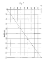
- Fig. 9 is a graph illustrating typical experimental results achieved with a device made according to the preferred embodiment of the invention.
- In the preferred embodiment of this invention, four temperature sensitive and radially extended elements are formed symmetrically on a thin substrate by a suitable process such as thick or thin film technology. The temperature sensitive element could be a material such as platinum, a semi-conductor (thermistor) suitably manufactured or a material such as diamond powder thin film thermistor suitably deposited which displays temperature dependent behaviour.
- The
substrate 10, shown in Fig. 1, is made of a material with poor heat conductivity properties such as a suitable ceramic, and has to be thin so that it can be positioned inside the reactor under a region of constant temperature where it will suffer no temperature gradients. In addition the use of a thin section reduces heat exchange to the surroundings and between the separate elements. This heat exchange between elements is further reduced by the choice of substrate material and by the inclusion of thin slots 2 between elements so as to break the heat conductive paths. The slots 2 also allow the gas from under the element to move to the top of the element encouraging proper gas exchange. As only two of the elements have a catalyst dispersed above them and the other two act as reference elements with no combustion over them, it is very important that no heat from the catalytic elements finds its way to the reference elements, as this would reduce the sensitivity. The four sensor elements have to be as near identical as possible. Figs. 2(a) and (b) show two suitable designs as examples, comprising the track of theresistive elements 6 and pads 7 to which the lead wires are connected. What is important is that the elements are as near identical as possible in their electrical characteristics (resistance value and sensitivity to temperature) and in their physical form, so as to reduce the common mode effects such as those due to the thermal conductivity of the background non combusting gases, the effect of flow variation, changes in the ambient temperature and in the temperature of the sample gas and so on. - The four elements are covered with a very thin glass layer which electrically insulates them from any overlays; but is thin enough to allow the heat to conduct to the elements. Each of the four elements is then covered with a uniform porous ceramic coating; but only in the ceramic above two diametrically opposed elements is the catalyst dispersed. Alternatively two diametrically opposed elements can be sealed with glass or any other inert coating whilst the other two treated as described earlier and doped with a catalyst. The catalyst could be one of the precious metals or their oxides (Pt, Rh, lr, Pd..) or any other suitable catalyst chosen usually to suit the combustible gas required to be monitored. It could be applied mixed with the ceramic, or dispersed as a compound which is decomposed later, or electro-deposited. It is important to disperse only the appropriate amount of catalyst. Too little will lead to loss of sensitivity, and too much leads to eventual sintering and blocking of pores in the ceramic.
- As shown in Fig. 3
substrate 10 is mounted inside a protective shroud assembly 11 which is seated by way ofledge 16, on a ceramic table 17 and fits onto theend assembly 15. The table 17 sits on theend assembly 15 and centrally over a four boreceramic unit 13.Wires 12 to the four element sensor are hermetically sealed within the four boreceramic unit 13 which is itself hermetically sealed at surface 14 to themetallic end assembly 15. - The total assembly of the sensor device, including the parts shown in Fig. 3 is shown in Fig. 4. The sensor head unit is inserted into a suitably designed
reactor vessel 25 and screwed gas tight through anappropriate seal 26 at the end. The reactor vessel is spatially heated on the outside by anappropriate heater 27 that surrounds tightly the reactor vessel. With the aid of a temperature sensor, such as aplatinum resistance thermometer 28, and appropriate electronics the temperature inside the reactor is controlled. - The temperature sensor position within the body is chosen carefully so that the sensor position is in the flat portion of the temperature profile along the axis of the reactor as shown in Fig. 5, which shows temperature plotted against distance from the sensor plate. As is apparent, the temperature distribution inside the reactor peaks and flattens at a position nearly in the middle of the reactor across its longitudinal axis and tails off nearly symmetrically towards each end. (The plot of fig. 5 was obtained for a reaction temperature of 260°C, with the external ambient temperature being 25°C.)
- The
sensor element 10 is positioned with its plane perpendicular to the axis of the reactor and at a point where the temperature gradient is nearly flat. This positioning and the fact that the element is very thin ensures very constant ambient temperature conditions around the sensor, and hence allows the sensor to resolve the very small temperature changes on its catalytic surface. - The gas mixture is admitted to one end of the reactor indicated by
arrow 29 and distributed round the inside of the body of the reactor, and the outside shroud of the element, so that it gradually reaches the inner temperature of the reactor, and at the point of low temperature gradient the gas has attained exactly the temperature of that region. The incoming gas, at that point, is induced to turn in partially towards the element as shown in Fig. 6 by the shaping 42 of the inner side of the shroud and the topinner end 43 of thevessel 25. A combination of flow and diffusion causes the gas to reach the surface of the element where the catalytic reaction takes place. The products of combustion 40 join some of the incoming gas and leave the vessel throughoutlet pipe 30. This is encouraged by the shape of the top part of the inner side of thereactor vessel 43. - In the above it is very important that the incoming gas should reach the same temperature of the elements and that the sensor disc should be positioned at the flat part of the temperature gradient inside the vessel. It is also important that the inside and particularly the top part of the reactor vessel is designed so that the element is not exposed to direct fast gas flow. The element should receive only very low direct flow and the arrival of gas at this sensor element should be mainly due to diffusion. The main part of the gas flow induces the gases at the surface of the element to be sucked to the outlet thereby removing the products of combustion and enabling fresh gas to arrive at the surface of the element.
- The four element sensor can be connected as a bridge circuit (DC or AC) with the non catalytic elements acting as reference units and the catalysed elements as combustible gas sensitive units. The bridge is balanced in the presence of a non-combustible gas such as air, and calibrated by admitting a combustible/air gas mixture of known concentration. With appropriate electronic circuitry and display the unbalance in the bridge due to the catalytic combustion of the combustible gas altering the resistance of the elements underneath it due to the resultant heat generated may be related to the concentration of the combustible gas. The choice of gas necessitates a choice of appropriate catalyst and appropriate operating temperature.
- In the following, particularly preferred materials and dimensions for the components of the arrangement described above are described.
- Athin (0.2mm) stabilized zirconia disc (10mm diameter) is chosen for the substrate. The zirconia has about four times worse thermal conductivity than alumina thus minimizing the heat feedback from the catalytic elements, which are heated by the combustion, to the non catalytic elements (reference elements). Fused quartz is another possible material for a substrate and the choice should be part of an overall material compatibility view. Slots 2 shown in Fig. 1 in a cross formation divide the disc into four quadrants. The shape of the slots and their dimensions (about 0.15x1.5mm) aim to increase the thermal resistance between the quadrants and hence reduce thermal feedback between elements without compromising the strength of the disc. The slots also provide a path for the gases under the disc to find their way to the surface of the disc thus improving gas circulation. The disc has also four
notches 3 on its outer perimeter (0.15x0.7mm). These provide anchor points for the lead wires and take the strain off the weld points. They are equally spaced around the perimeter of the disc and slightly displaced to one side of the cross pattern. This ensures their correct positioning in respect to the termination of the resistive elements. - Four identical resistive elements are produced one on each quadrant. The designs shown in Figs. 2 (a) & (b) are for thick film screen printing technology, although other technologies of producing the elements may be used. The design of the pattern should be considered in conjunction with the technology to be used to implemented it and should aim to produce as nearly as possible identical electrical and spatial characteristics. Each of patterns a or b produce the right characteristics if used with the right screens. A platinum resistor ink such as Engelhardt T-11502 produces very good elements when fired and sintered correctly, these can be further matched so that the resistor bridge elements are matched to better than 0.1%.
- One side of the end termination 7 of each
resistor 6 overlaps thenotches 3 described earlier so that a platinum/10% Irwire of about 0.2 mm diameter, which is slightly flattened on its end can be brought through the notch, bent over the pad and soldered, welded or cemented to it with Pt paste; ensuring thus a good oh- mic contact. The symmetry of the design and the positioning of the disc under a constant temperature ensures that the thermoelectric effects are negligible. This wire is preferred because its thermal coefficient of expansion is near that of the zirconia and because the alloy is stronger than pure platinum wire. - A very thin electrically insulating glass coating is then applied over all the disc uniformly covering all four elements. A glass such as Hereaus Cermallay-EMDI-9053 would provide suitable cover.
- A slurry of zirconia is then screened over the elements and fired appropriately to provide a stable and porous matrix of about 0.1 mm thick and of an average pore size of about 0.5-5 microns. Other suitable ceramic materials could be used, such as alumina for example.
- The chosen catalyst, platinum in the case of sensing CO as the combustible gas, may be premixed as a very fine powder in the zirconia slurry. Asimpler way of introducing it is to use chloroplatinic acid, dispersed on the two required elements and then heated to decomposition to form platinum. Other techniques such as electroplating may be used.
- A final thin coat of ceramic (e.g zirconia, alumina) may be added if extra protection is needed to the surface. It acts effectively as a filter. Its presence usually reduces the sensitivity of the sensor. Again the non- catalytic reference elements can be sealed by material other than zirconia e.g. glass.
- A short length of four bore alumina rod 13 (about 6mm long, 5mm diameter and 0.75 bore) shown in end and side views in Figs. 7(a) and (b) has four lengths of
nicrome wire 12 hermetically sealed into it with appropriate sealing glass and at the same time the rod is sealed into thestainless steel base 15 with the same glass 14. Table 17 shown in first and second ends and side views in Figs. 8(a), (b) and (c) (14mm diameter 2mm top and 6mm legs) has four holes in the top (c) which the wires from the disc go through leaving the disc about 1 mm above the table. The lower end of the table is cut across like a cross (a) leaving effectively fourlegs 50 for positioning and seating correctly on the rod and inside the shroud, and allowingspace 51 to house the wires and access to weld them or fuse them from the side. The wires from the disc and those from the rod are bent and welded together. The slots under the table leave ample space to do that. A stainless steel shroud 11 is pushed into position aligning the table with the base until itsinner edge 16 rests on the top of the table. Suitable lead wires are connected to the end wires. - The sensor head is then pushed into the
reactor unit 25 which is made of stainless steel, and sealed gas tight with screws and ahigh temperature gasket 26. Thetemperature sensor 28 and theheater 27 are placed in the correct places. - The temperature control system (not shown) which drives the
heater 27 and senses the temperature by theplatinum resistance thermometer 28 ensures constant operating temperature. For CO a good operating temperature is 280 degrees Centigrade. An oscillator feeds the bridge with AC and the output is initially balanced when air is passed through the reactor. The electronic system is calibrated to read zero. Aspan gas say 2000ppm CO in air is admitted into the reactor, the balance of the bridge is disturbed and a voltage output from the electronic system say 1 volt will correspond to 2000ppm CO. Fig. 9, which is a plot of output voltage against CO(ppm), shows a typical curve of voltage output against the gas concentration. - The advantages of the system described become apparent on examining the results. The high sensitivity allows the resolution of about a few ppm CO; an improvement of at least 10 times of what was possible earlier with devices such as Pellistors. The effect of water vapour and ambient gases are reduced by a factor of at least ten, improving the baseline stability and permitting lower ranges to be monitored.
Claims (10)
Applications Claiming Priority (2)
| Application Number | Priority Date | Filing Date | Title |
|---|---|---|---|
| GB9301104 | 1993-01-21 | ||
| GB939301104A GB9301104D0 (en) | 1993-01-21 | 1993-01-21 | Sensor for combustible gases |
Publications (3)
| Publication Number | Publication Date |
|---|---|
| EP0608122A2 true EP0608122A2 (en) | 1994-07-27 |
| EP0608122A3 EP0608122A3 (en) | 1995-11-02 |
| EP0608122B1 EP0608122B1 (en) | 1998-03-25 |
Family
ID=10729034
Family Applications (1)
| Application Number | Title | Priority Date | Filing Date |
|---|---|---|---|
| EP94300386A Expired - Lifetime EP0608122B1 (en) | 1993-01-21 | 1994-01-19 | Sensor for combustible gases |
Country Status (6)
| Country | Link |
|---|---|
| US (1) | US5549871A (en) |
| EP (1) | EP0608122B1 (en) |
| JP (1) | JPH0749324A (en) |
| CA (1) | CA2113664A1 (en) |
| DE (1) | DE69409138T2 (en) |
| GB (1) | GB9301104D0 (en) |
Cited By (10)
| Publication number | Priority date | Publication date | Assignee | Title |
|---|---|---|---|---|
| ES2121699A1 (en) * | 1996-12-10 | 1998-12-01 | Consejo Superior Investigacion | PORTABLE SYSTEM TO DETERMINE VOLATILE ORGANIC COMPOUNDS IN SOILS. |
| EP0886137A1 (en) * | 1997-06-11 | 1998-12-23 | CTS Corporation | A gas sensor with multiple exposed active elements |
| WO2001006246A1 (en) * | 1999-07-15 | 2001-01-25 | Fev Motorentechnik Gmbh | Sensor assembly for detecting proportions of gas in gas streams containing particles |
| DE19830709C2 (en) * | 1998-07-09 | 2002-10-31 | Daimler Chrysler Ag | Measuring transducer for the detection of hydrocarbons in gases |
| WO2003012424A1 (en) * | 2001-08-02 | 2003-02-13 | Servomex Group Ltd | Measuring cell for determining a paramagnetic gas |
| WO2004003537A3 (en) * | 2002-06-28 | 2004-04-29 | Rosemount Analytical Inc | Device for sensing the concentration of a combustible specie |
| EP1452853A4 (en) * | 2001-11-15 | 2005-06-01 | Riken Keiki Kk | GAS SENSOR |
| WO2008142568A3 (en) * | 2007-05-18 | 2009-05-22 | Life Safety Distribution Ag | Thermally insulating ceramic substrates for gas sensors |
| RU2483297C1 (en) * | 2011-12-12 | 2013-05-27 | Федеральное государственное бюджетное образовательное учреждение высшего профессионального образования "Омский государственный университет им. Ф.М. Достоевского" | Thermochemical sensor |
| US9091658B2 (en) | 2011-02-08 | 2015-07-28 | Servomex Group Limited | Paramagnetic gas sensor apparatus and adjustment method |
Families Citing this family (11)
| Publication number | Priority date | Publication date | Assignee | Title |
|---|---|---|---|---|
| JP3494508B2 (en) * | 1995-06-26 | 2004-02-09 | 日本碍子株式会社 | Combustible gas sensor, method for measuring combustible gas concentration, and method for detecting catalyst deterioration |
| US5804703A (en) * | 1997-06-09 | 1998-09-08 | General Motors Corporation | Circuit for a combustible gas sensor |
| GB9819160D0 (en) * | 1998-09-02 | 1998-10-28 | City Tech | Pellistor |
| DE19916797C2 (en) * | 1999-04-14 | 2001-08-16 | Daimler Chrysler Ag | Semiconductor gas sensor with housing and method for measuring gas concentrations |
| US6719950B2 (en) * | 2001-11-14 | 2004-04-13 | Robert Bosch Corporation | Miniaturized exhaust gas sensor |
| US6812708B2 (en) * | 2002-06-04 | 2004-11-02 | Scott Technologies, Inc. | Combustible-gas measuring instrument |
| US7656302B2 (en) * | 2006-11-20 | 2010-02-02 | Honeywell International Inc. | Sensing chamber with enhanced ambient atmospheric flow |
| US20110039216A1 (en) * | 2008-04-22 | 2011-02-17 | Basf Se | Process for controlling the addition of an auxiliary fuel |
| KR20140002398A (en) | 2012-06-29 | 2014-01-08 | 현대자동차주식회사 | System for soot sensing of diesel vehicle |
| KR20140002399A (en) * | 2012-06-29 | 2014-01-08 | 현대자동차주식회사 | System for sof sensing of diesel vehicle |
| US11474064B2 (en) | 2018-03-03 | 2022-10-18 | James SAWADA | Sensor and method for detecting combustible gas |
Family Cites Families (13)
| Publication number | Priority date | Publication date | Assignee | Title |
|---|---|---|---|---|
| US3092799A (en) * | 1958-02-18 | 1963-06-04 | Nat Res Dev | Apparatus for detecting combustible gases having an electrically conductive member enveloped in a refractory material |
| US3200011A (en) * | 1959-02-03 | 1965-08-10 | Nat Res Dev | Electrically heatable filaments |
| US3564474A (en) * | 1968-06-04 | 1971-02-16 | Nat Res Dev | Electrically heatable elements |
| JPS5316309A (en) * | 1976-07-30 | 1978-02-15 | Kobe Steel Ltd | Annealing method for preventing graphitization of surface of low carbon cold rolled steel sheet |
| US4325912A (en) * | 1980-07-01 | 1982-04-20 | Beckman Instruments, Inc. | Carbon monoxide detection apparatus |
| US4355056A (en) * | 1981-03-31 | 1982-10-19 | The Babcock & Wilcox Company | Method of manufacturing a combustibles sensor |
| DE3328385A1 (en) * | 1983-08-05 | 1985-02-21 | Kraftwerk Union AG, 4330 Mülheim | PROBE FOR DETECTING FLAMMABLE GASES |
| US4560585A (en) * | 1983-12-23 | 1985-12-24 | Rexnord Inc. | Poison resistant combustible gas sensor |
| US4572900A (en) * | 1984-04-25 | 1986-02-25 | The United States Of America As Represented By The Secretary Of The Navy | Organic semiconductor vapor sensing method |
| DE3519397A1 (en) * | 1985-05-30 | 1986-12-04 | Siemens AG, 1000 Berlin und 8000 München | Sensor for gas analysis and detection |
| US4870025A (en) * | 1985-09-30 | 1989-09-26 | Ford Motor Company | Method of sensing methane gas-I |
| JPH01109250A (en) * | 1987-10-22 | 1989-04-26 | Toshiba Corp | Gas sensor |
| US5338515A (en) * | 1990-08-17 | 1994-08-16 | Catalytica, Inc. | SO2 sensor |
-
1993
- 1993-01-21 GB GB939301104A patent/GB9301104D0/en active Pending
-
1994
- 1994-01-18 CA CA002113664A patent/CA2113664A1/en not_active Abandoned
- 1994-01-19 EP EP94300386A patent/EP0608122B1/en not_active Expired - Lifetime
- 1994-01-19 DE DE69409138T patent/DE69409138T2/en not_active Expired - Lifetime
- 1994-01-21 JP JP6005399A patent/JPH0749324A/en active Pending
-
1995
- 1995-10-13 US US08/542,713 patent/US5549871A/en not_active Expired - Lifetime
Cited By (20)
| Publication number | Priority date | Publication date | Assignee | Title |
|---|---|---|---|---|
| ES2121699A1 (en) * | 1996-12-10 | 1998-12-01 | Consejo Superior Investigacion | PORTABLE SYSTEM TO DETERMINE VOLATILE ORGANIC COMPOUNDS IN SOILS. |
| EP0886137A1 (en) * | 1997-06-11 | 1998-12-23 | CTS Corporation | A gas sensor with multiple exposed active elements |
| DE19830709C2 (en) * | 1998-07-09 | 2002-10-31 | Daimler Chrysler Ag | Measuring transducer for the detection of hydrocarbons in gases |
| WO2001006246A1 (en) * | 1999-07-15 | 2001-01-25 | Fev Motorentechnik Gmbh | Sensor assembly for detecting proportions of gas in gas streams containing particles |
| WO2003012424A1 (en) * | 2001-08-02 | 2003-02-13 | Servomex Group Ltd | Measuring cell for determining a paramagnetic gas |
| US7102346B2 (en) | 2001-08-02 | 2006-09-05 | Servomex Group Ltd. | Measuring cell for determining characteristics of a paramagnetic gas based on gas flow sweeping past a test element |
| EP2023133A3 (en) * | 2001-11-15 | 2009-02-25 | Riken Keiki Co., Ltd. | Gas sensor |
| EP1452853A4 (en) * | 2001-11-15 | 2005-06-01 | Riken Keiki Kk | GAS SENSOR |
| US7479255B2 (en) | 2001-11-15 | 2009-01-20 | Riken Keiki Co., Ltd. | Gas sensor |
| CN100458428C (en) * | 2001-11-15 | 2009-02-04 | 理研计器株式会社 | Gas sensor |
| WO2004003537A3 (en) * | 2002-06-28 | 2004-04-29 | Rosemount Analytical Inc | Device for sensing the concentration of a combustible specie |
| US7527717B2 (en) | 2002-06-28 | 2009-05-05 | Rosemount Analytical, Inc. | Sulfur resistant sensors |
| WO2008142568A3 (en) * | 2007-05-18 | 2009-05-22 | Life Safety Distribution Ag | Thermally insulating ceramic substrates for gas sensors |
| CN101784889A (en) * | 2007-05-18 | 2010-07-21 | 生命安全销售股份公司 | The thermally insulating ceramic substrates that is used for gas sensor |
| US8024958B2 (en) | 2007-05-18 | 2011-09-27 | Life Safety Distribution Ag | Gas sensors with thermally insulating ceramic substrates |
| CN101784889B (en) * | 2007-05-18 | 2013-03-06 | 生命安全销售股份公司 | Thermally Insulating Ceramic Substrates for Gas Sensors |
| US8490467B2 (en) | 2007-05-18 | 2013-07-23 | Life Safety Distribution Ag | Thermally insulating ceramic substrates for gas sensors |
| KR101504951B1 (en) * | 2007-05-18 | 2015-03-23 | 라이프 세이프티 디스트리뷰션 아게 | Thermal insulation ceramic substrate for gas sensors |
| US9091658B2 (en) | 2011-02-08 | 2015-07-28 | Servomex Group Limited | Paramagnetic gas sensor apparatus and adjustment method |
| RU2483297C1 (en) * | 2011-12-12 | 2013-05-27 | Федеральное государственное бюджетное образовательное учреждение высшего профессионального образования "Омский государственный университет им. Ф.М. Достоевского" | Thermochemical sensor |
Also Published As
| Publication number | Publication date |
|---|---|
| US5549871A (en) | 1996-08-27 |
| EP0608122B1 (en) | 1998-03-25 |
| DE69409138D1 (en) | 1998-04-30 |
| DE69409138T2 (en) | 1998-08-20 |
| GB9301104D0 (en) | 1993-03-10 |
| JPH0749324A (en) | 1995-02-21 |
| EP0608122A3 (en) | 1995-11-02 |
| CA2113664A1 (en) | 1994-07-22 |
Similar Documents
| Publication | Publication Date | Title |
|---|---|---|
| EP0608122B1 (en) | Sensor for combustible gases | |
| EP1330640B1 (en) | Catalytic sensor | |
| US4453397A (en) | Gas detecting sensor | |
| US4814059A (en) | Electrochemical device having a heater and leak protection electrode | |
| KR101504951B1 (en) | Thermal insulation ceramic substrate for gas sensors | |
| CA1191897A (en) | Gas sensor | |
| EP0167297A2 (en) | Electrochemical element | |
| JPH07190863A (en) | Temperature sensor | |
| GB2046921A (en) | Measuring sensor for determining the constituents of flowing gases | |
| AU2001285148A1 (en) | Catalytic sensor | |
| US5844122A (en) | Sensor with output correcting function | |
| US4528086A (en) | Oxygen sensor with heater | |
| JPH11153571A (en) | Oxygen sensor element | |
| JPH04216452A (en) | Sensor for simultaneously detecting composition of mixed gas and speed of gas | |
| EP0168938A1 (en) | Electrochemical element | |
| US4935118A (en) | Self heated sensor package | |
| RU2114422C1 (en) | Semiconductor gas sensor | |
| US5779980A (en) | Gas sensor having a compounded catalytic structure | |
| JP4806232B2 (en) | Semiconductor gas sensor and semiconductor gas sensor for gas chromatograph | |
| JP2615138B2 (en) | Composite gas sensor | |
| JPH053973Y2 (en) | ||
| EP0697593A1 (en) | Low power catalytic combustible gas detector | |
| WO1986005882A1 (en) | Self heated sensor package | |
| JPH07107523B2 (en) | Gas detector manufacturing method | |
| JPS60114757A (en) | Gas detecting bridge |
Legal Events
| Date | Code | Title | Description |
|---|---|---|---|
| PUAI | Public reference made under article 153(3) epc to a published international application that has entered the european phase |
Free format text: ORIGINAL CODE: 0009012 |
|
| AK | Designated contracting states |
Kind code of ref document: A2 Designated state(s): BE CH DE FR GB IT LI NL |
|
| PUAL | Search report despatched |
Free format text: ORIGINAL CODE: 0009013 |
|
| AK | Designated contracting states |
Kind code of ref document: A3 Designated state(s): BE CH DE FR GB IT LI NL |
|
| 17P | Request for examination filed |
Effective date: 19960409 |
|
| GRAG | Despatch of communication of intention to grant |
Free format text: ORIGINAL CODE: EPIDOS AGRA |
|
| GRAG | Despatch of communication of intention to grant |
Free format text: ORIGINAL CODE: EPIDOS AGRA |
|
| GRAH | Despatch of communication of intention to grant a patent |
Free format text: ORIGINAL CODE: EPIDOS IGRA |
|
| 17Q | First examination report despatched |
Effective date: 19970526 |
|
| GRAH | Despatch of communication of intention to grant a patent |
Free format text: ORIGINAL CODE: EPIDOS IGRA |
|
| GRAA | (expected) grant |
Free format text: ORIGINAL CODE: 0009210 |
|
| AK | Designated contracting states |
Kind code of ref document: B1 Designated state(s): BE CH DE FR GB IT LI NL |
|
| PG25 | Lapsed in a contracting state [announced via postgrant information from national office to epo] |
Ref country code: NL Free format text: LAPSE BECAUSE OF FAILURE TO SUBMIT A TRANSLATION OF THE DESCRIPTION OR TO PAY THE FEE WITHIN THE PRESCRIBED TIME-LIMIT Effective date: 19980325 Ref country code: LI Free format text: LAPSE BECAUSE OF FAILURE TO SUBMIT A TRANSLATION OF THE DESCRIPTION OR TO PAY THE FEE WITHIN THE PRESCRIBED TIME-LIMIT Effective date: 19980325 Ref country code: CH Free format text: LAPSE BECAUSE OF FAILURE TO SUBMIT A TRANSLATION OF THE DESCRIPTION OR TO PAY THE FEE WITHIN THE PRESCRIBED TIME-LIMIT Effective date: 19980325 Ref country code: BE Free format text: LAPSE BECAUSE OF FAILURE TO SUBMIT A TRANSLATION OF THE DESCRIPTION OR TO PAY THE FEE WITHIN THE PRESCRIBED TIME-LIMIT Effective date: 19980325 |
|
| REG | Reference to a national code |
Ref country code: CH Ref legal event code: EP |
|
| ET | Fr: translation filed | ||
| REF | Corresponds to: |
Ref document number: 69409138 Country of ref document: DE Date of ref document: 19980430 |
|
| ITF | It: translation for a ep patent filed | ||
| NLV1 | Nl: lapsed or annulled due to failure to fulfill the requirements of art. 29p and 29m of the patents act | ||
| REG | Reference to a national code |
Ref country code: CH Ref legal event code: PL |
|
| PLBE | No opposition filed within time limit |
Free format text: ORIGINAL CODE: 0009261 |
|
| STAA | Information on the status of an ep patent application or granted ep patent |
Free format text: STATUS: NO OPPOSITION FILED WITHIN TIME LIMIT |
|
| 26N | No opposition filed | ||
| REG | Reference to a national code |
Ref country code: GB Ref legal event code: IF02 |
|
| PGFP | Annual fee paid to national office [announced via postgrant information from national office to epo] |
Ref country code: IT Payment date: 20120119 Year of fee payment: 19 |
|
| PGFP | Annual fee paid to national office [announced via postgrant information from national office to epo] |
Ref country code: DE Payment date: 20130116 Year of fee payment: 20 Ref country code: GB Payment date: 20130116 Year of fee payment: 20 Ref country code: FR Payment date: 20130204 Year of fee payment: 20 |
|
| REG | Reference to a national code |
Ref country code: DE Ref legal event code: R071 Ref document number: 69409138 Country of ref document: DE |
|
| REG | Reference to a national code |
Ref country code: GB Ref legal event code: PE20 Expiry date: 20140118 |
|
| PG25 | Lapsed in a contracting state [announced via postgrant information from national office to epo] |
Ref country code: DE Free format text: LAPSE BECAUSE OF EXPIRATION OF PROTECTION Effective date: 20140121 Ref country code: GB Free format text: LAPSE BECAUSE OF EXPIRATION OF PROTECTION Effective date: 20140118 |