EP0607979A1 - Single column cryogenic rectification system for producing nitrogen gas at elevated pressure and high purity - Google Patents
Single column cryogenic rectification system for producing nitrogen gas at elevated pressure and high purity Download PDFInfo
- Publication number
- EP0607979A1 EP0607979A1 EP94100820A EP94100820A EP0607979A1 EP 0607979 A1 EP0607979 A1 EP 0607979A1 EP 94100820 A EP94100820 A EP 94100820A EP 94100820 A EP94100820 A EP 94100820A EP 0607979 A1 EP0607979 A1 EP 0607979A1
- Authority
- EP
- European Patent Office
- Prior art keywords
- nitrogen
- column
- fluid
- feed
- oxygen
- Prior art date
- Legal status (The legal status is an assumption and is not a legal conclusion. Google has not performed a legal analysis and makes no representation as to the accuracy of the status listed.)
- Granted
Links
Images


Classifications
-
- F—MECHANICAL ENGINEERING; LIGHTING; HEATING; WEAPONS; BLASTING
- F25—REFRIGERATION OR COOLING; COMBINED HEATING AND REFRIGERATION SYSTEMS; HEAT PUMP SYSTEMS; MANUFACTURE OR STORAGE OF ICE; LIQUEFACTION SOLIDIFICATION OF GASES
- F25J—LIQUEFACTION, SOLIDIFICATION OR SEPARATION OF GASES OR GASEOUS OR LIQUEFIED GASEOUS MIXTURES BY PRESSURE AND COLD TREATMENT OR BY BRINGING THEM INTO THE SUPERCRITICAL STATE
- F25J3/00—Processes or apparatus for separating the constituents of gaseous or liquefied gaseous mixtures involving the use of liquefaction or solidification
- F25J3/02—Processes or apparatus for separating the constituents of gaseous or liquefied gaseous mixtures involving the use of liquefaction or solidification by rectification, i.e. by continuous interchange of heat and material between a vapour stream and a liquid stream
- F25J3/04—Processes or apparatus for separating the constituents of gaseous or liquefied gaseous mixtures involving the use of liquefaction or solidification by rectification, i.e. by continuous interchange of heat and material between a vapour stream and a liquid stream for air
- F25J3/04248—Generation of cold for compensating heat leaks or liquid production, e.g. by Joule-Thompson expansion
- F25J3/04284—Generation of cold for compensating heat leaks or liquid production, e.g. by Joule-Thompson expansion using internal refrigeration by open-loop gas work expansion, e.g. of intermediate or oxygen enriched (waste-)streams
- F25J3/0429—Generation of cold for compensating heat leaks or liquid production, e.g. by Joule-Thompson expansion using internal refrigeration by open-loop gas work expansion, e.g. of intermediate or oxygen enriched (waste-)streams of feed air, e.g. used as waste or product air or expanded into an auxiliary column
- F25J3/04296—Claude expansion, i.e. expanded into the main or high pressure column
-
- F—MECHANICAL ENGINEERING; LIGHTING; HEATING; WEAPONS; BLASTING
- F25—REFRIGERATION OR COOLING; COMBINED HEATING AND REFRIGERATION SYSTEMS; HEAT PUMP SYSTEMS; MANUFACTURE OR STORAGE OF ICE; LIQUEFACTION SOLIDIFICATION OF GASES
- F25J—LIQUEFACTION, SOLIDIFICATION OR SEPARATION OF GASES OR GASEOUS OR LIQUEFIED GASEOUS MIXTURES BY PRESSURE AND COLD TREATMENT OR BY BRINGING THEM INTO THE SUPERCRITICAL STATE
- F25J3/00—Processes or apparatus for separating the constituents of gaseous or liquefied gaseous mixtures involving the use of liquefaction or solidification
- F25J3/02—Processes or apparatus for separating the constituents of gaseous or liquefied gaseous mixtures involving the use of liquefaction or solidification by rectification, i.e. by continuous interchange of heat and material between a vapour stream and a liquid stream
- F25J3/04—Processes or apparatus for separating the constituents of gaseous or liquefied gaseous mixtures involving the use of liquefaction or solidification by rectification, i.e. by continuous interchange of heat and material between a vapour stream and a liquid stream for air
- F25J3/04006—Providing pressurised feed air or process streams within or from the air fractionation unit
- F25J3/04078—Providing pressurised feed air or process streams within or from the air fractionation unit providing pressurized products by liquid compression and vaporisation with cold recovery, i.e. so-called internal compression
- F25J3/04084—Providing pressurised feed air or process streams within or from the air fractionation unit providing pressurized products by liquid compression and vaporisation with cold recovery, i.e. so-called internal compression of nitrogen
-
- F—MECHANICAL ENGINEERING; LIGHTING; HEATING; WEAPONS; BLASTING
- F25—REFRIGERATION OR COOLING; COMBINED HEATING AND REFRIGERATION SYSTEMS; HEAT PUMP SYSTEMS; MANUFACTURE OR STORAGE OF ICE; LIQUEFACTION SOLIDIFICATION OF GASES
- F25J—LIQUEFACTION, SOLIDIFICATION OR SEPARATION OF GASES OR GASEOUS OR LIQUEFIED GASEOUS MIXTURES BY PRESSURE AND COLD TREATMENT OR BY BRINGING THEM INTO THE SUPERCRITICAL STATE
- F25J3/00—Processes or apparatus for separating the constituents of gaseous or liquefied gaseous mixtures involving the use of liquefaction or solidification
- F25J3/02—Processes or apparatus for separating the constituents of gaseous or liquefied gaseous mixtures involving the use of liquefaction or solidification by rectification, i.e. by continuous interchange of heat and material between a vapour stream and a liquid stream
- F25J3/04—Processes or apparatus for separating the constituents of gaseous or liquefied gaseous mixtures involving the use of liquefaction or solidification by rectification, i.e. by continuous interchange of heat and material between a vapour stream and a liquid stream for air
- F25J3/04151—Purification and (pre-)cooling of the feed air; recuperative heat-exchange with product streams
- F25J3/04163—Hot end purification of the feed air
- F25J3/04169—Hot end purification of the feed air by adsorption of the impurities
- F25J3/04175—Hot end purification of the feed air by adsorption of the impurities at a pressure of substantially more than the highest pressure column
-
- F—MECHANICAL ENGINEERING; LIGHTING; HEATING; WEAPONS; BLASTING
- F25—REFRIGERATION OR COOLING; COMBINED HEATING AND REFRIGERATION SYSTEMS; HEAT PUMP SYSTEMS; MANUFACTURE OR STORAGE OF ICE; LIQUEFACTION SOLIDIFICATION OF GASES
- F25J—LIQUEFACTION, SOLIDIFICATION OR SEPARATION OF GASES OR GASEOUS OR LIQUEFIED GASEOUS MIXTURES BY PRESSURE AND COLD TREATMENT OR BY BRINGING THEM INTO THE SUPERCRITICAL STATE
- F25J3/00—Processes or apparatus for separating the constituents of gaseous or liquefied gaseous mixtures involving the use of liquefaction or solidification
- F25J3/02—Processes or apparatus for separating the constituents of gaseous or liquefied gaseous mixtures involving the use of liquefaction or solidification by rectification, i.e. by continuous interchange of heat and material between a vapour stream and a liquid stream
- F25J3/04—Processes or apparatus for separating the constituents of gaseous or liquefied gaseous mixtures involving the use of liquefaction or solidification by rectification, i.e. by continuous interchange of heat and material between a vapour stream and a liquid stream for air
- F25J3/04248—Generation of cold for compensating heat leaks or liquid production, e.g. by Joule-Thompson expansion
- F25J3/04333—Generation of cold for compensating heat leaks or liquid production, e.g. by Joule-Thompson expansion using quasi-closed loop internal vapor compression refrigeration cycles, e.g. of intermediate or oxygen enriched (waste-)streams
- F25J3/04339—Generation of cold for compensating heat leaks or liquid production, e.g. by Joule-Thompson expansion using quasi-closed loop internal vapor compression refrigeration cycles, e.g. of intermediate or oxygen enriched (waste-)streams of air
-
- F—MECHANICAL ENGINEERING; LIGHTING; HEATING; WEAPONS; BLASTING
- F25—REFRIGERATION OR COOLING; COMBINED HEATING AND REFRIGERATION SYSTEMS; HEAT PUMP SYSTEMS; MANUFACTURE OR STORAGE OF ICE; LIQUEFACTION SOLIDIFICATION OF GASES
- F25J—LIQUEFACTION, SOLIDIFICATION OR SEPARATION OF GASES OR GASEOUS OR LIQUEFIED GASEOUS MIXTURES BY PRESSURE AND COLD TREATMENT OR BY BRINGING THEM INTO THE SUPERCRITICAL STATE
- F25J3/00—Processes or apparatus for separating the constituents of gaseous or liquefied gaseous mixtures involving the use of liquefaction or solidification
- F25J3/02—Processes or apparatus for separating the constituents of gaseous or liquefied gaseous mixtures involving the use of liquefaction or solidification by rectification, i.e. by continuous interchange of heat and material between a vapour stream and a liquid stream
- F25J3/04—Processes or apparatus for separating the constituents of gaseous or liquefied gaseous mixtures involving the use of liquefaction or solidification by rectification, i.e. by continuous interchange of heat and material between a vapour stream and a liquid stream for air
- F25J3/04248—Generation of cold for compensating heat leaks or liquid production, e.g. by Joule-Thompson expansion
- F25J3/04333—Generation of cold for compensating heat leaks or liquid production, e.g. by Joule-Thompson expansion using quasi-closed loop internal vapor compression refrigeration cycles, e.g. of intermediate or oxygen enriched (waste-)streams
- F25J3/04351—Generation of cold for compensating heat leaks or liquid production, e.g. by Joule-Thompson expansion using quasi-closed loop internal vapor compression refrigeration cycles, e.g. of intermediate or oxygen enriched (waste-)streams of nitrogen
-
- F—MECHANICAL ENGINEERING; LIGHTING; HEATING; WEAPONS; BLASTING
- F25—REFRIGERATION OR COOLING; COMBINED HEATING AND REFRIGERATION SYSTEMS; HEAT PUMP SYSTEMS; MANUFACTURE OR STORAGE OF ICE; LIQUEFACTION SOLIDIFICATION OF GASES
- F25J—LIQUEFACTION, SOLIDIFICATION OR SEPARATION OF GASES OR GASEOUS OR LIQUEFIED GASEOUS MIXTURES BY PRESSURE AND COLD TREATMENT OR BY BRINGING THEM INTO THE SUPERCRITICAL STATE
- F25J3/00—Processes or apparatus for separating the constituents of gaseous or liquefied gaseous mixtures involving the use of liquefaction or solidification
- F25J3/02—Processes or apparatus for separating the constituents of gaseous or liquefied gaseous mixtures involving the use of liquefaction or solidification by rectification, i.e. by continuous interchange of heat and material between a vapour stream and a liquid stream
- F25J3/04—Processes or apparatus for separating the constituents of gaseous or liquefied gaseous mixtures involving the use of liquefaction or solidification by rectification, i.e. by continuous interchange of heat and material between a vapour stream and a liquid stream for air
- F25J3/044—Processes or apparatus for separating the constituents of gaseous or liquefied gaseous mixtures involving the use of liquefaction or solidification by rectification, i.e. by continuous interchange of heat and material between a vapour stream and a liquid stream for air using a single pressure main column system only
-
- F—MECHANICAL ENGINEERING; LIGHTING; HEATING; WEAPONS; BLASTING
- F25—REFRIGERATION OR COOLING; COMBINED HEATING AND REFRIGERATION SYSTEMS; HEAT PUMP SYSTEMS; MANUFACTURE OR STORAGE OF ICE; LIQUEFACTION SOLIDIFICATION OF GASES
- F25J—LIQUEFACTION, SOLIDIFICATION OR SEPARATION OF GASES OR GASEOUS OR LIQUEFIED GASEOUS MIXTURES BY PRESSURE AND COLD TREATMENT OR BY BRINGING THEM INTO THE SUPERCRITICAL STATE
- F25J2200/00—Processes or apparatus using separation by rectification
- F25J2200/72—Refluxing the column with at least a part of the totally condensed overhead gas
-
- F—MECHANICAL ENGINEERING; LIGHTING; HEATING; WEAPONS; BLASTING
- F25—REFRIGERATION OR COOLING; COMBINED HEATING AND REFRIGERATION SYSTEMS; HEAT PUMP SYSTEMS; MANUFACTURE OR STORAGE OF ICE; LIQUEFACTION SOLIDIFICATION OF GASES
- F25J—LIQUEFACTION, SOLIDIFICATION OR SEPARATION OF GASES OR GASEOUS OR LIQUEFIED GASEOUS MIXTURES BY PRESSURE AND COLD TREATMENT OR BY BRINGING THEM INTO THE SUPERCRITICAL STATE
- F25J2200/00—Processes or apparatus using separation by rectification
- F25J2200/76—Refluxing the column with condensed overhead gas being cycled in a quasi-closed loop refrigeration cycle
-
- F—MECHANICAL ENGINEERING; LIGHTING; HEATING; WEAPONS; BLASTING
- F25—REFRIGERATION OR COOLING; COMBINED HEATING AND REFRIGERATION SYSTEMS; HEAT PUMP SYSTEMS; MANUFACTURE OR STORAGE OF ICE; LIQUEFACTION SOLIDIFICATION OF GASES
- F25J—LIQUEFACTION, SOLIDIFICATION OR SEPARATION OF GASES OR GASEOUS OR LIQUEFIED GASEOUS MIXTURES BY PRESSURE AND COLD TREATMENT OR BY BRINGING THEM INTO THE SUPERCRITICAL STATE
- F25J2250/00—Details related to the use of reboiler-condensers
- F25J2250/20—Boiler-condenser with multiple exchanger cores in parallel or with multiple re-boiling or condensing streams
-
- F—MECHANICAL ENGINEERING; LIGHTING; HEATING; WEAPONS; BLASTING
- F25—REFRIGERATION OR COOLING; COMBINED HEATING AND REFRIGERATION SYSTEMS; HEAT PUMP SYSTEMS; MANUFACTURE OR STORAGE OF ICE; LIQUEFACTION SOLIDIFICATION OF GASES
- F25J—LIQUEFACTION, SOLIDIFICATION OR SEPARATION OF GASES OR GASEOUS OR LIQUEFIED GASEOUS MIXTURES BY PRESSURE AND COLD TREATMENT OR BY BRINGING THEM INTO THE SUPERCRITICAL STATE
- F25J2250/00—Details related to the use of reboiler-condensers
- F25J2250/30—External or auxiliary boiler-condenser in general, e.g. without a specified fluid or one fluid is not a primary air component or an intermediate fluid
- F25J2250/40—One fluid being air
-
- F—MECHANICAL ENGINEERING; LIGHTING; HEATING; WEAPONS; BLASTING
- F25—REFRIGERATION OR COOLING; COMBINED HEATING AND REFRIGERATION SYSTEMS; HEAT PUMP SYSTEMS; MANUFACTURE OR STORAGE OF ICE; LIQUEFACTION SOLIDIFICATION OF GASES
- F25J—LIQUEFACTION, SOLIDIFICATION OR SEPARATION OF GASES OR GASEOUS OR LIQUEFIED GASEOUS MIXTURES BY PRESSURE AND COLD TREATMENT OR BY BRINGING THEM INTO THE SUPERCRITICAL STATE
- F25J2250/00—Details related to the use of reboiler-condensers
- F25J2250/30—External or auxiliary boiler-condenser in general, e.g. without a specified fluid or one fluid is not a primary air component or an intermediate fluid
- F25J2250/42—One fluid being nitrogen
-
- F—MECHANICAL ENGINEERING; LIGHTING; HEATING; WEAPONS; BLASTING
- F25—REFRIGERATION OR COOLING; COMBINED HEATING AND REFRIGERATION SYSTEMS; HEAT PUMP SYSTEMS; MANUFACTURE OR STORAGE OF ICE; LIQUEFACTION SOLIDIFICATION OF GASES
- F25J—LIQUEFACTION, SOLIDIFICATION OR SEPARATION OF GASES OR GASEOUS OR LIQUEFIED GASEOUS MIXTURES BY PRESSURE AND COLD TREATMENT OR BY BRINGING THEM INTO THE SUPERCRITICAL STATE
- F25J2270/00—Refrigeration techniques used
- F25J2270/02—Internal refrigeration with liquid vaporising loop
-
- Y—GENERAL TAGGING OF NEW TECHNOLOGICAL DEVELOPMENTS; GENERAL TAGGING OF CROSS-SECTIONAL TECHNOLOGIES SPANNING OVER SEVERAL SECTIONS OF THE IPC; TECHNICAL SUBJECTS COVERED BY FORMER USPC CROSS-REFERENCE ART COLLECTIONS [XRACs] AND DIGESTS
- Y10—TECHNICAL SUBJECTS COVERED BY FORMER USPC
- Y10S—TECHNICAL SUBJECTS COVERED BY FORMER USPC CROSS-REFERENCE ART COLLECTIONS [XRACs] AND DIGESTS
- Y10S62/00—Refrigeration
- Y10S62/901—Single column
-
- Y—GENERAL TAGGING OF NEW TECHNOLOGICAL DEVELOPMENTS; GENERAL TAGGING OF CROSS-SECTIONAL TECHNOLOGIES SPANNING OVER SEVERAL SECTIONS OF THE IPC; TECHNICAL SUBJECTS COVERED BY FORMER USPC CROSS-REFERENCE ART COLLECTIONS [XRACs] AND DIGESTS
- Y10—TECHNICAL SUBJECTS COVERED BY FORMER USPC
- Y10S—TECHNICAL SUBJECTS COVERED BY FORMER USPC CROSS-REFERENCE ART COLLECTIONS [XRACs] AND DIGESTS
- Y10S62/00—Refrigeration
- Y10S62/939—Partial feed stream expansion, air
Definitions
- This invention relates generally to the cryogenic rectification of mixtures comprising oxygen and nitrogen, e.g. air, and more particularly to the production of elevated pressure nitrogen gas product with improved purity.
- the cryogenic separation of mixtures such as air to produce nitrogen is a well established industrial process. Liquid and vapor are passed in countercurrent contact through a column of a cryogenic rectification plant and the difference in vapor pressure between the oxygen and nitrogen causes nitrogen to concentrate in the vapor and oxygen to concentrate in the liquid. The lower the pressure is in the separation column, the easier is the separation due to vapor pressure differential. Accordingly, the separation for producing product nitrogen is generally carried out at a relatively low pressure.
- Another way of producing high pressure nitrogen product gas is to operate the column of the cryogenic air separation plant at an elevated pressure. In many cases, this is disadvantageous because the column operating pressure required to produce the desired product pressure is higher than that pressure which gives the optimal cycle efficiency, resulting in increased operating costs.
- a cryogenic rectification method for producing elevated pressure nitrogen gas comprising:
- Apparatus for producing elevated pressure nitrogen gas by cryogenic rectification comprising:
- distillation means a distillation or fractionation column or zone, i.e., a contacting column or zone wherein liquid and vapor phases are countercurrently contacted to effect separation of a fluid mixture, as for example, by contacting of the vapor and liquid phases on vaporliquid contacting elements such as on a series of vertically spaced trays or plates mounted within the column and/or on packing elements which may be structured and/or random packing elements.
- vaporliquid contacting elements such as on a series of vertically spaced trays or plates mounted within the column and/or on packing elements which may be structured and/or random packing elements.
- Vapor and liquid contacting separation processes depend on the difference in vapor pressures for the components.
- the high vapor pressure (or more volatile or low boiling) component will tend to concentrate in the vapor phase while the low vapor pressure (or less volatile or high boiling) component will tend to concentrate in the liquid phase.
- Distillation is the separation process whereby heating of a liquid mixture can be used to concentrate the volatile component(s) in the vapor phase and thereby the less volatile components(s) in the liquid phase.
- Partial condensation is the separation process whereby cooling of a vapor mixture can be used to concentrate the volatile component(s) in the vapor phase and thereby the less volatile component(s) in the liquid phase.
- Rectification is the separation process that combines successive partial vaporizations and condensations as obtained by a countercurrent treatment of the vapor and liquid phases.
- the countercurrent contacting of the vapor and liquid phases can include integral or differential contact between the phases.
- Separation process arrangements that utilize the principles of rectification to separate mixtures are often interchangeably termed rectification columns, distillation columns, or fractionation columns.
- Cryogenic rectification is a rectification process carried out, at least in part, at low temperatures, such as at temperatures at or below 133 degrees K.
- directly heat exchange means the bringing of two fluid streams into heat exchange relation without any physical contact or intermixing of the fluids with each other.
- feed air means a mixture comprising primarily nitrogen and oxygen such as air.
- equilibrium stage means a contact process between vapor and liquid such that the exiting vapor and liquid streams are in equilibrium.
- upper portion and lower portion of a column mean respectively the upper half and the lower half of the column.
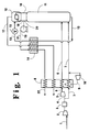
- Figure 1 is a schematic representation of one embodiment of the invention wherein nitrogen-rich liquid is vaporized by heat exchange with feed.
- FIG. 2 is a schematic representation of another embodiment of the invention wherein additional nitrogen-rich liquid is generated by heat exchange with feed.
- Figure 3 is a schematic representation of another embodiment of the invention wherein nitrogen-rich liquid is vaporized by heat exchange with nitrogen vapor taken from the column.
- Figure 4 is a schematic representation of another embodiment of the invention wherein nitrogen-rich liquid is vaporized by heat exchange with oxygen-enriched vapor.
- feed air 1 is compressed by passage through main compressor 2 and then cleaned of high boiling impurities such as carbon dioxide and water vapor by passage through molecular sieve prepurifier 3. Reversing heat exchangers may also be employed to clean the feed of high boiling impurities.
- a fraction 4 of the compressed feed air is further compressed by passage through booster compressor 5. Resulting further compressed fraction 6 as well as remaining feed air fraction 7 are cooled by passage through main heat exchanger 8.
- a portion 9 of further compressed fraction 6 is removed from heat exchanger 8 at an intermediate point, work expanded by passage through turboexpander 10 to generate refrigeration and passed into stream 7.
- Further compressed fraction 6 is at least partially condensed by passage through heat exchanger 8. Resulting cooled streams 6 and 7 are passed in cryogenic rectification column 11. Preferably stream 6 is passed into column 11 at a point at least one equilibrium stage above the point where stream 7 is passed into column 11.
- Column 11 is operating at a pressure less than 125 pounds per square inch absolute (psia), preferably less than 70 psia and most preferably at a pressure less than 60 psia. Generally, the operating pressure of column 11 will be within the range of from 35 to 50 psia. The relatively low operating pressure of column 11 facilitates the separation of the feed. Within column 11, the feed is separated by cryogenic rectification into nitrogen-rich vapor and oxygen-enriched liquid. Column 11 comprises at least one top condenser such as top condenser 12.
- Oxygen-enriched liquid generally having an oxygen concentration within the range of from 30 to 55 mole percent, is passed in stream 13 through heat exchanger 14 wherein it is subcooled, passed through valve 15 and then passed into top condenser 12 of column 11.
- Nitrogen-rich vapor 16 is also passed into top condenser 12 wherein oxygen-enriched liquid is vaporized by indirect heat exchange with nitrogen-rich vapor taken from the column to produce nitrogen-rich liquid and oxygen-enriched vapor.
- Resulting oxygen-enriched vapor 17 is warmed by passage through heat exchangers 14 and 8 and removed from the system.
- Nitrogen-rich liquid 18 is increased in pressure preferably by passage through a liquid pump such as liquid pump 19. A portion 20 of nitrogen-rich liquid is used as reflux for column 11.
- the pressure of nitrogen-rich liquid is elevated to be within the range of from 45 to 250 psia. Any other effective means of raising the pressure of nitrogen-rich liquid may also be used in the practice of this invention.
- Pressurized nitrogen-rich liquid 21 is warmed by passage through heat exchanger 14 and is vaporized by passage through heat exchanger 8 by indirect heat exchange with the cooling compressed feed.
- the compressed fluid at least partially condenses by the indirect heat exchange with the pressurized nitrogen-rich liquid.
- the resulting elevated pressure nitrogen gas 22 is recovered as product containing from 10 ppm (molar) to 0.1 ppb (molar) oxygen and at a pressure within the range of from 45 to 250 psia without need for product gas compression.
- at least 50 percent and preferably at least 90 percent of the nitrogen-rich vapor recovered from the process is taken from the column, pumped to elevated pressure and vaporized.
- FIG 2 illustrates another embodiment of the invention which employs two top condensers as part of the rectification column.
- the numerals in Figure 2 correspond to those of Figure 1 for the corresponding elements and these corresponding elements will not be described again in detail.
- all of the feed air is further compressed and a portion 30 is withdrawn from an intermediate point of heat exchanger 8, turboexpanded through expander 10 and passed into column 11.
- Another portion 31 of the feed air is passed into auxiliary top condenser 32 wherein there is also passed nitrogen-rich vapor 16.
- Feed air is passed out from auxiliary top condenser 32 as stream 33, warmed by passage through heat exchangers 14 and 8 is recombined with feed stream 1 between compressors 1 and 5.
- a portion 34 of the nitrogen-rich liquid may be recovered as product liquid nitrogen in addition to the product nitrogen gas.
- the embodiment illustrated in Figure 2 is advantageous in that a higher recovery of nitrogen is possible over that attainable with the embodiment illustrated in Figure 1. This is due to a reduction in the amount of liquid feed passed into the column over what would be the case with the embodiment illustrated in Figure 1.
- Figure 3 illustrates another embodiment of the invention wherein nitrogen fluid is used to vaporize the nitrogen-rich liquid.
- the numerals in Figure 3 correspond to those of Figure 1 for the corresponding elements and these corresponding elements will not be described again in detail.
- all of the further compressed feed air passes through heat exchanger 8 and turboexpander 10 as stream 35 and is passed into column 10.
- a vapor stream 39 comprising from 98 to 99.999 percent nitrogen is withdrawn from column 11, warmed by passage through heat exchangers 14 and 8, compressed by passage through compressor 38 and passed back through heat exchanger 8 wherein it serves to vaporize nitrogen-rich liquid 21.
- Resulting nitrogen fluid 37 which preferably has been at least partly condensed by the passage through heat exchanger 8, is passed back through heat exchanger 14, through valve 36 and back into column 11, preferably at a point at least one equilibrium stage above the point where stream 39 was withdrawn from column 11.
- the heat exchange between the compressed nitrogen stream and the nitrogen-rich liquid is shown as occurring in single heat exchanger 8. However, this is not required and such heat exchange could occur in a separate heat exchanger. That is, main heat exchanger 8 could alternatively be two or more separate heat exchangers.
- FIG 4 illustrates another embodiment of the invention wherein oxygen-enriched fluid is used to vaporize the nitrogen-rich liquid.
- the numerals in Figure 4 correspond to those of the preceding Figures for the corresponding elements and these corresponding elements will not be described again in detail.
- a portion 41 of oxygen-enriched fluid 17 is compressed by passage through compressor 42 and passed back through heat exchanger 8 wherein it serves to vaporize nitrogen-rich liquid 21.
- Resulting oxygen-enriched fluid 43 which preferably has been at least partially condensed, is passed into stream 13 and then through heat exchanger 14 and valve 15 into top condenser 12.
- the heat exchange between the compressed oxygen-enriched vapor and the nitrogen-rich liquid is shown as occurring in single heat exchanger 8. However, this is not necessary and such heat exchange could occur in a separate heat exchanger. That is, main heat exchanger 8 could alternatively be two separate heat exchangers.
- the main heat exchanger also serves as the product vaporizer.
- the nitrogen-rich liquid may be vaporized in a separate heat exchanger from the main heat exchanger wherein the feed is cooled, and in such a case, this separate heat exchanger would be the product vaporizer of the invention.
Abstract
Description
- This invention relates generally to the cryogenic rectification of mixtures comprising oxygen and nitrogen, e.g. air, and more particularly to the production of elevated pressure nitrogen gas product with improved purity.
- The cryogenic separation of mixtures such as air to produce nitrogen is a well established industrial process. Liquid and vapor are passed in countercurrent contact through a column of a cryogenic rectification plant and the difference in vapor pressure between the oxygen and nitrogen causes nitrogen to concentrate in the vapor and oxygen to concentrate in the liquid. The lower the pressure is in the separation column, the easier is the separation due to vapor pressure differential. Accordingly, the separation for producing product nitrogen is generally carried out at a relatively low pressure.
- Often product nitrogen gas is desired at a high pressure. In such situations, the product nitrogen gas is compressed to the desired pressure in a compressor. This compression is costly in terms of energy costs as well as capital costs for the product compressors. Moreover, the compression of the nitrogen product gas may generate impurities such as particulates and these impurities may be detrimental if the nitrogen gas is to be used in an application requiring high purity, such as in the manufacture of semiconductors. In such instances, a further purification step for the nitrogen gas product may be necessary.
- Another way of producing high pressure nitrogen product gas is to operate the column of the cryogenic air separation plant at an elevated pressure. In many cases, this is disadvantageous because the column operating pressure required to produce the desired product pressure is higher than that pressure which gives the optimal cycle efficiency, resulting in increased operating costs.
- Accordingly, it is an object of this invention to provide a cryogenic rectification system wherein product nitrogen gas may be efficiently produced while avoiding high operating pressures within the cryogenic rectification plant and avoiding the need to compress nitrogen gas product.
- The above and other objects which will become apparent to one skilled in the art upon a reading of this disclosure are attained by the present invention one aspect of which is:
A cryogenic rectification method for producing elevated pressure nitrogen gas comprising: - (A) compressing a feed comprising nitrogen and oxygen;
- (B) cooling compressed feed and passing resulting cooled feed into a column;
- (C) separating feed within the column by cryogenic rectification into nitrogen-rich vapor and oxygen-enriched liquid;
- (D) Vaporizing oxygen-enriched liquid by indirect heat exchange with nitrogen-rich vapor to produce nitrogen-rich liquid and oxygen-enriched vapor;
- (E) increasing the pressure of nitrogen-rich liquid to produce elevated pressure nitrogen-rich liquid;
- (F) vaporizing elevated pressure nitrogen-rich liquid by indirect heat exchange with compressed fluid to produce elevated pressure nitrogen gas; and
- (G) recovering elevated pressure nitrogen gas as product.
- Another aspect of this invention is:
Apparatus for producing elevated pressure nitrogen gas by cryogenic rectification comprising: - (A) a column and means for providing a feed comprising nitrogen and oxygen into the column;
- (B) means for passing fluid taken from the lower portion of the column in indirect heat exchange with fluid taken from the upper portion of the column;
- (C) means for increasing the pressure of fluid taken from the upper portion of the column;
- (D) a product vaporizer and means for passing said increased pressure fluid to the product vaporizer for vaporization;
- (E) a compressor and means for passing fluid from the compressor to the product vaporizer to vaporize said increased pressure fluid; and
- (F) means for recovering as product increased pressure vaporized fluid from the product vaporizer.
- As used herein, the term "column" means a distillation or fractionation column or zone, i.e., a contacting column or zone wherein liquid and vapor phases are countercurrently contacted to effect separation of a fluid mixture, as for example, by contacting of the vapor and liquid phases on vaporliquid contacting elements such as on a series of vertically spaced trays or plates mounted within the column and/or on packing elements which may be structured and/or random packing elements. For a further discussion of distillation columns, see the Chemical Engineers' Handbook. Fifth Edition, edited by R. H. Perry and C. H. Chilton, McGraw-Hill Book Company, New York,
Section 13, "Distillation", B. D. Smith. et al., page 13-3, The Continuous Distillation Process. - Vapor and liquid contacting separation processes depend on the difference in vapor pressures for the components. The high vapor pressure (or more volatile or low boiling) component will tend to concentrate in the vapor phase while the low vapor pressure (or less volatile or high boiling) component will tend to concentrate in the liquid phase. Distillation is the separation process whereby heating of a liquid mixture can be used to concentrate the volatile component(s) in the vapor phase and thereby the less volatile components(s) in the liquid phase. Partial condensation is the separation process whereby cooling of a vapor mixture can be used to concentrate the volatile component(s) in the vapor phase and thereby the less volatile component(s) in the liquid phase. Rectification, or continuous distillation, is the separation process that combines successive partial vaporizations and condensations as obtained by a countercurrent treatment of the vapor and liquid phases. The countercurrent contacting of the vapor and liquid phases can include integral or differential contact between the phases. Separation process arrangements that utilize the principles of rectification to separate mixtures are often interchangeably termed rectification columns, distillation columns, or fractionation columns. Cryogenic rectification is a rectification process carried out, at least in part, at low temperatures, such as at temperatures at or below 133 degrees K.
- As used herein, the term "indirect heat exchange" means the bringing of two fluid streams into heat exchange relation without any physical contact or intermixing of the fluids with each other.
- As used herein, the term "feed air" means a mixture comprising primarily nitrogen and oxygen such as air.
- As used herein, the term "equilibrium stage" means a contact process between vapor and liquid such that the exiting vapor and liquid streams are in equilibrium.
- As used herein, the terms "upper portion" and "lower portion" of a column mean respectively the upper half and the lower half of the column.
- Figure 1 is a schematic representation of one embodiment of the invention wherein nitrogen-rich liquid is vaporized by heat exchange with feed.
- Figure 2 is a schematic representation of another embodiment of the invention wherein additional nitrogen-rich liquid is generated by heat exchange with feed.
- Figure 3 is a schematic representation of another embodiment of the invention wherein nitrogen-rich liquid is vaporized by heat exchange with nitrogen vapor taken from the column.
- Figure 4 is a schematic representation of another embodiment of the invention wherein nitrogen-rich liquid is vaporized by heat exchange with oxygen-enriched vapor.
- The invention will be described in detail with reference to the Drawings.
- Referring now to Figure 1, feed air 1 is compressed by passage through
main compressor 2 and then cleaned of high boiling impurities such as carbon dioxide and water vapor by passage throughmolecular sieve prepurifier 3. Reversing heat exchangers may also be employed to clean the feed of high boiling impurities. A fraction 4 of the compressed feed air is further compressed by passage throughbooster compressor 5. Resulting further compressedfraction 6 as well as remainingfeed air fraction 7 are cooled by passage throughmain heat exchanger 8. A portion 9 of further compressedfraction 6 is removed fromheat exchanger 8 at an intermediate point, work expanded by passage throughturboexpander 10 to generate refrigeration and passed intostream 7. Further compressedfraction 6 is at least partially condensed by passage throughheat exchanger 8. Resulting cooledstreams cryogenic rectification column 11. Preferablystream 6 is passed intocolumn 11 at a point at least one equilibrium stage above the point wherestream 7 is passed intocolumn 11. -
Column 11 is operating at a pressure less than 125 pounds per square inch absolute (psia), preferably less than 70 psia and most preferably at a pressure less than 60 psia. Generally, the operating pressure ofcolumn 11 will be within the range of from 35 to 50 psia. The relatively low operating pressure ofcolumn 11 facilitates the separation of the feed. Withincolumn 11, the feed is separated by cryogenic rectification into nitrogen-rich vapor and oxygen-enriched liquid.Column 11 comprises at least one top condenser such astop condenser 12. Oxygen-enriched liquid, generally having an oxygen concentration within the range of from 30 to 55 mole percent, is passed instream 13 throughheat exchanger 14 wherein it is subcooled, passed throughvalve 15 and then passed intotop condenser 12 ofcolumn 11. Nitrogen-rich vapor 16 is also passed intotop condenser 12 wherein oxygen-enriched liquid is vaporized by indirect heat exchange with nitrogen-rich vapor taken from the column to produce nitrogen-rich liquid and oxygen-enriched vapor. Resulting oxygen-enrichedvapor 17 is warmed by passage throughheat exchangers - Nitrogen-
rich liquid 18 is increased in pressure preferably by passage through a liquid pump such asliquid pump 19. Aportion 20 of nitrogen-rich liquid is used as reflux forcolumn 11. The pressure of nitrogen-rich liquid is elevated to be within the range of from 45 to 250 psia. Any other effective means of raising the pressure of nitrogen-rich liquid may also be used in the practice of this invention. Pressurized nitrogen-rich liquid 21 is warmed by passage throughheat exchanger 14 and is vaporized by passage throughheat exchanger 8 by indirect heat exchange with the cooling compressed feed. Preferably the compressed fluid at least partially condenses by the indirect heat exchange with the pressurized nitrogen-rich liquid. The resulting elevatedpressure nitrogen gas 22 is recovered as product containing from 10 ppm (molar) to 0.1 ppb (molar) oxygen and at a pressure within the range of from 45 to 250 psia without need for product gas compression. In the practice of this invention, at least 50 percent and preferably at least 90 percent of the nitrogen-rich vapor recovered from the process is taken from the column, pumped to elevated pressure and vaporized. - Figure 2 illustrates another embodiment of the invention which employs two top condensers as part of the rectification column. The numerals in Figure 2 correspond to those of Figure 1 for the corresponding elements and these corresponding elements will not be described again in detail. Referring now to Figure 2, all of the feed air is further compressed and a
portion 30 is withdrawn from an intermediate point ofheat exchanger 8, turboexpanded throughexpander 10 and passed intocolumn 11. Anotherportion 31 of the feed air is passed into auxiliarytop condenser 32 wherein there is also passed nitrogen-rich vapor 16. Feed air is passed out from auxiliarytop condenser 32 asstream 33, warmed by passage throughheat exchangers compressors 1 and 5. Aportion 34 of the nitrogen-rich liquid may be recovered as product liquid nitrogen in addition to the product nitrogen gas. The embodiment illustrated in Figure 2 is advantageous in that a higher recovery of nitrogen is possible over that attainable with the embodiment illustrated in Figure 1. This is due to a reduction in the amount of liquid feed passed into the column over what would be the case with the embodiment illustrated in Figure 1. - Figure 3 illustrates another embodiment of the invention wherein nitrogen fluid is used to vaporize the nitrogen-rich liquid. The numerals in Figure 3 correspond to those of Figure 1 for the corresponding elements and these corresponding elements will not be described again in detail. Referring now to Figure 3, all of the further compressed feed air passes through
heat exchanger 8 andturboexpander 10 asstream 35 and is passed intocolumn 10. Avapor stream 39 comprising from 98 to 99.999 percent nitrogen is withdrawn fromcolumn 11, warmed by passage throughheat exchangers compressor 38 and passed back throughheat exchanger 8 wherein it serves to vaporize nitrogen-rich liquid 21. Resultingnitrogen fluid 37, which preferably has been at least partly condensed by the passage throughheat exchanger 8, is passed back throughheat exchanger 14, throughvalve 36 and back intocolumn 11, preferably at a point at least one equilibrium stage above the point wherestream 39 was withdrawn fromcolumn 11. In the embodiment illustrated in Figure 3, the heat exchange between the compressed nitrogen stream and the nitrogen-rich liquid is shown as occurring insingle heat exchanger 8. However, this is not required and such heat exchange could occur in a separate heat exchanger. That is,main heat exchanger 8 could alternatively be two or more separate heat exchangers. - Figure 4 illustrates another embodiment of the invention wherein oxygen-enriched fluid is used to vaporize the nitrogen-rich liquid. The numerals in Figure 4 correspond to those of the preceding Figures for the corresponding elements and these corresponding elements will not be described again in detail. Referring now to Figure 4, a
portion 41 of oxygen-enrichedfluid 17 is compressed by passage throughcompressor 42 and passed back throughheat exchanger 8 wherein it serves to vaporize nitrogen-rich liquid 21. Resulting oxygen-enrichedfluid 43, which preferably has been at least partially condensed, is passed intostream 13 and then throughheat exchanger 14 andvalve 15 intotop condenser 12. In the embodiment illustrated in Figure 4, the heat exchange between the compressed oxygen-enriched vapor and the nitrogen-rich liquid is shown as occurring insingle heat exchanger 8. However, this is not necessary and such heat exchange could occur in a separate heat exchanger. That is,main heat exchanger 8 could alternatively be two separate heat exchangers. - Now, by the use of this invention, one can produce nitrogen gas with a single column cryogenic rectification plant at an elevated pressure while avoiding the need to compress product nitrogen gas. Although the invention has been described in detail with reference to certain preferred embodiments, those skilled in the art will recognize that there are other embodiments of the invention within the spirit and the scope of the claims. For example, in each of the embodiments illustrated in the Figures, the main heat exchanger also serves as the product vaporizer. However, as also discussed in the specification, the nitrogen-rich liquid may be vaporized in a separate heat exchanger from the main heat exchanger wherein the feed is cooled, and in such a case, this separate heat exchanger would be the product vaporizer of the invention.
Claims (8)
- A cryogenic rectification method for producing elevated pressure nitrogen gas comprising:(A) compressing a feed comprising nitrogen and oxygen;(B) cooling compressed feed and passing resulting cooled feed into a column;(C) separating feed within the column by cryogenic rectification into nitrogen-rich vapor and oxygen-enriched liquid;(D) vaporizing oxygen-enriched liquid by indirect heat exchange with nitrogen-rich vapor to produce nitrogen-rich liquid and oxygen-enriched vapor;(E) increasing the pressure of nitrogen-rich liquid to produce elevated pressure nitrogen-rich liquid;(F) vaporizing elevated pressure nitrogen-rich liquid by indirect heat exchange with compressed fluid to produce elevated pressure nitrogen gas; and(G) recovering elevated pressure nitrogen gas as product.
- The method of claim 1 wherein the compressed fluid is feed.
- The method of claim 1 wherein the compressed fluid is oxygen-enriched vapor.
- The method of claim 1 wherein the compressed fluid is nitrogen-containing fluid taken from the column and returned to the column after the heat exchange with the pressurized nitrogen-rich liquid.
- The method of claim 1 wherein the compressed fluid is at least partially condensed by the heat exchange with the pressurized nitrogen-rich liquid.
- The method of claim 1 wherein at least some cooled, compressed feed is turboexpanded prior to being passed into the column.
- The method of claim 1 further comprising producing some nitrogen-rich liquid by indirect heat exchange of nitrogen-rich vapor with a portion of the feed.
- Apparatus for producing elevated pressure nitrogen gas by cryogenic rectification comprising:(A) a column and means for providing a feed comprising nitrogen and oxygen into the column;(B) means for passing fluid taken from the lower portion of the column in indirect heat exchange with fluid taken from the upper portion of the column;(C) means for increasing the pressure of fluid taken from the upper portion of the column;(D) a product vaporizer and means for passing said increased pressure fluid to the product vaporizer for vaporization;(E) a compressor and means for passing fluid from the compressor to the product vaporizer to vaporize said increased pressure fluid; and(F) means for recovering as product increased pressure vaporized fluid from the product vaporizer.
Applications Claiming Priority (2)
| Application Number | Priority Date | Filing Date | Title |
|---|---|---|---|
| US6408 | 1993-01-21 | ||
| US08/006,408 US5303556A (en) | 1993-01-21 | 1993-01-21 | Single column cryogenic rectification system for producing nitrogen gas at elevated pressure and high purity |
Publications (2)
| Publication Number | Publication Date |
|---|---|
| EP0607979A1 true EP0607979A1 (en) | 1994-07-27 |
| EP0607979B1 EP0607979B1 (en) | 1998-08-19 |
Family
ID=21720716
Family Applications (1)
| Application Number | Title | Priority Date | Filing Date |
|---|---|---|---|
| EP94100820A Expired - Lifetime EP0607979B1 (en) | 1993-01-21 | 1994-01-20 | Single column cryogenic rectification system for producing nitrogen gas at elevated pressure and high purity |
Country Status (9)
| Country | Link |
|---|---|
| US (1) | US5303556A (en) |
| EP (1) | EP0607979B1 (en) |
| JP (1) | JPH06219713A (en) |
| KR (1) | KR940018643A (en) |
| CN (1) | CN1092855A (en) |
| BR (1) | BR9400135A (en) |
| CA (1) | CA2113864A1 (en) |
| DE (1) | DE69412521T2 (en) |
| ES (1) | ES2118984T3 (en) |
Cited By (1)
| Publication number | Priority date | Publication date | Assignee | Title |
|---|---|---|---|---|
| DE19954593B4 (en) * | 1999-11-12 | 2008-04-10 | Linde Ag | Method and apparatus for the cryogenic separation of air |
Families Citing this family (13)
| Publication number | Priority date | Publication date | Assignee | Title |
|---|---|---|---|---|
| US5355682A (en) * | 1993-09-15 | 1994-10-18 | Air Products And Chemicals, Inc. | Cryogenic air separation process producing elevated pressure nitrogen by pumped liquid nitrogen |
| US5475980A (en) * | 1993-12-30 | 1995-12-19 | L'air Liquide, Societe Anonyme Pour L'etude L'exploitation Des Procedes Georges Claude | Process and installation for production of high pressure gaseous fluid |
| US5706675A (en) * | 1995-08-18 | 1998-01-13 | G & A Associates | High efficiency oxygen/air separation system |
| US5666823A (en) * | 1996-01-31 | 1997-09-16 | Air Products And Chemicals, Inc. | High pressure combustion turbine and air separation system integration |
| DE19735154A1 (en) * | 1996-10-30 | 1998-05-07 | Linde Ag | Producing compressed nitrogen@ by low temperature distillation of air in rectifier system |
| US5794458A (en) * | 1997-01-30 | 1998-08-18 | The Boc Group, Inc. | Method and apparatus for producing gaseous oxygen |
| US6006545A (en) * | 1998-08-14 | 1999-12-28 | L'air Liquide, Societe Anonyme Pour L'etude Et L'exploitation Des Procedes | Liquefier process |
| DE10018200A1 (en) * | 2000-04-12 | 2001-10-18 | Linde Gas Ag | Method and device for obtaining pressurized nitrogen by low-temperature separation of air |
| US6351969B1 (en) | 2001-01-31 | 2002-03-05 | Praxair Technology, Inc. | Cryogenic nitrogen production system using a single brazement |
| US6568209B1 (en) | 2002-09-06 | 2003-05-27 | Praxair Technology, Inc. | Cryogenic air separation system with dual section main heat exchanger |
| JP4340705B2 (en) * | 2004-04-26 | 2009-10-07 | ハウメディカ・オステオニクス・コーポレイション | Avascular meniscal repair and regeneration stent |
| CN111071465A (en) * | 2020-01-06 | 2020-04-28 | 南京航空航天大学 | Low-temperature refrigeration nitrogen-making oil tank inerting system and working method thereof |
| WO2022179748A1 (en) | 2021-02-25 | 2022-09-01 | Linde Gmbh | Process and plant for providing compressed nitrogen |
Citations (4)
| Publication number | Priority date | Publication date | Assignee | Title |
|---|---|---|---|---|
| GB870349A (en) | 1957-11-14 | 1961-06-14 | Joy Mfg Co | Method and apparatus for the separation of gas mixtures |
| DE1501723A1 (en) * | 1966-01-13 | 1969-06-26 | Linde Ag | Method and device for generating gaseous high-pressure oxygen in the low-temperature rectification of air |
| GB2088542A (en) * | 1980-11-26 | 1982-06-09 | Union Carbide Corp | Process for the production of high pressure oxygen gas |
| EP0078063A2 (en) * | 1981-10-27 | 1983-05-04 | Air Products And Chemicals, Inc. | A process for the separation of essentially pure nitrogen |
Family Cites Families (22)
| Publication number | Priority date | Publication date | Assignee | Title |
|---|---|---|---|---|
| DE2402246A1 (en) * | 1974-01-18 | 1975-07-31 | Linde Ag | PROCESS FOR THE RECOVERY OF OXYGEN OF MEDIUM PURITY |
| GB2080929B (en) * | 1980-07-22 | 1984-02-08 | Air Prod & Chem | Producing gaseous oxygen |
| US4604117A (en) * | 1984-11-15 | 1986-08-05 | Union Carbide Corporation | Hybrid nitrogen generator with auxiliary column drive |
| US4594085A (en) * | 1984-11-15 | 1986-06-10 | Union Carbide Corporation | Hybrid nitrogen generator with auxiliary reboiler drive |
| US4595405A (en) * | 1984-12-21 | 1986-06-17 | Air Products And Chemicals, Inc. | Process for the generation of gaseous and/or liquid nitrogen |
| FR2578532B1 (en) * | 1985-03-11 | 1990-05-04 | Air Liquide | PROCESS AND PLANT FOR THE PRODUCTION OF NITROGEN |
| US4617036A (en) * | 1985-10-29 | 1986-10-14 | Air Products And Chemicals, Inc. | Tonnage nitrogen air separation with side reboiler condenser |
| US4662917A (en) * | 1986-05-30 | 1987-05-05 | Air Products And Chemicals, Inc. | Process for the separation of air |
| US4662918A (en) * | 1986-05-30 | 1987-05-05 | Air Products And Chemicals, Inc. | Air separation process |
| US4662916A (en) * | 1986-05-30 | 1987-05-05 | Air Products And Chemicals, Inc. | Process for the separation of air |
| US4796431A (en) * | 1986-07-15 | 1989-01-10 | Erickson Donald C | Nitrogen partial expansion refrigeration for cryogenic air separation |
| JP2755953B2 (en) * | 1988-05-19 | 1998-05-25 | テイサン株式会社 | Nitrogen gas production method |
| US4834785A (en) * | 1988-06-20 | 1989-05-30 | Air Products And Chemicals, Inc. | Cryogenic nitrogen generator with nitrogen expander |
| US4848996A (en) * | 1988-10-06 | 1989-07-18 | Air Products And Chemicals, Inc. | Nitrogen generator with waste distillation and recycle of waste distillation overhead |
| US4867773A (en) * | 1988-10-06 | 1989-09-19 | Air Products And Chemicals, Inc. | Cryogenic process for nitrogen production with oxygen-enriched recycle |
| US4872893A (en) * | 1988-10-06 | 1989-10-10 | Air Products And Chemicals, Inc. | Process for the production of high pressure nitrogen |
| FR2651035A1 (en) * | 1989-08-18 | 1991-02-22 | Air Liquide | PROCESS FOR THE PRODUCTION OF NITROGEN BY DISTILLATION |
| US5148680A (en) * | 1990-06-27 | 1992-09-22 | Union Carbide Industrial Gases Technology Corporation | Cryogenic air separation system with dual product side condenser |
| US5123946A (en) * | 1990-08-22 | 1992-06-23 | Liquid Air Engineering Corporation | Cryogenic nitrogen generator with bottom reboiler and nitrogen expander |
| US5098457A (en) * | 1991-01-22 | 1992-03-24 | Union Carbide Industrial Gases Technology Corporation | Method and apparatus for producing elevated pressure nitrogen |
| US5144808A (en) * | 1991-02-12 | 1992-09-08 | Liquid Air Engineering Corporation | Cryogenic air separation process and apparatus |
| JP2909678B2 (en) * | 1991-03-11 | 1999-06-23 | レール・リキード・ソシエテ・アノニム・プール・レテュード・エ・レクスプロワタシオン・デ・プロセデ・ジョルジュ・クロード | Method and apparatus for producing gaseous oxygen under pressure |
-
1993
- 1993-01-21 US US08/006,408 patent/US5303556A/en not_active Expired - Fee Related
-
1994
- 1994-01-19 BR BR9400135A patent/BR9400135A/en not_active IP Right Cessation
- 1994-01-20 CN CN94100508A patent/CN1092855A/en active Pending
- 1994-01-20 CA CA002113864A patent/CA2113864A1/en not_active Abandoned
- 1994-01-20 JP JP6018812A patent/JPH06219713A/en active Pending
- 1994-01-20 EP EP94100820A patent/EP0607979B1/en not_active Expired - Lifetime
- 1994-01-20 DE DE69412521T patent/DE69412521T2/en not_active Expired - Fee Related
- 1994-01-20 ES ES94100820T patent/ES2118984T3/en not_active Expired - Lifetime
- 1994-01-20 KR KR1019940001023A patent/KR940018643A/en active IP Right Grant
Patent Citations (4)
| Publication number | Priority date | Publication date | Assignee | Title |
|---|---|---|---|---|
| GB870349A (en) | 1957-11-14 | 1961-06-14 | Joy Mfg Co | Method and apparatus for the separation of gas mixtures |
| DE1501723A1 (en) * | 1966-01-13 | 1969-06-26 | Linde Ag | Method and device for generating gaseous high-pressure oxygen in the low-temperature rectification of air |
| GB2088542A (en) * | 1980-11-26 | 1982-06-09 | Union Carbide Corp | Process for the production of high pressure oxygen gas |
| EP0078063A2 (en) * | 1981-10-27 | 1983-05-04 | Air Products And Chemicals, Inc. | A process for the separation of essentially pure nitrogen |
Cited By (1)
| Publication number | Priority date | Publication date | Assignee | Title |
|---|---|---|---|---|
| DE19954593B4 (en) * | 1999-11-12 | 2008-04-10 | Linde Ag | Method and apparatus for the cryogenic separation of air |
Also Published As
| Publication number | Publication date |
|---|---|
| CN1092855A (en) | 1994-09-28 |
| DE69412521D1 (en) | 1998-09-24 |
| CA2113864A1 (en) | 1994-07-22 |
| JPH06219713A (en) | 1994-08-09 |
| ES2118984T3 (en) | 1998-10-01 |
| EP0607979B1 (en) | 1998-08-19 |
| DE69412521T2 (en) | 1999-03-25 |
| BR9400135A (en) | 1994-08-09 |
| KR940018643A (en) | 1994-08-18 |
| US5303556A (en) | 1994-04-19 |
Similar Documents
| Publication | Publication Date | Title |
|---|---|---|
| CA2145445C (en) | Cryogenic rectification system for producing elevated pressure nitrogen | |
| US5463871A (en) | Side column cryogenic rectification system for producing lower purity oxygen | |
| EP0496355B1 (en) | Method and apparatus for producing elevated pressure nitrogen | |
| KR100225681B1 (en) | Cryogenic rectification system for producing lower purity oxygen | |
| US5233838A (en) | Auxiliary column cryogenic rectification system | |
| EP0766053B1 (en) | Cryogenic rectification system for producing dual purity oxygen | |
| EP0921367A2 (en) | Production of nitrogen | |
| US5303556A (en) | Single column cryogenic rectification system for producing nitrogen gas at elevated pressure and high purity | |
| CA2232405C (en) | Cryogenic rectification system for producing high pressure nitrogen and high pressure oxygen | |
| US5263327A (en) | High recovery cryogenic rectification system | |
| US6279345B1 (en) | Cryogenic air separation system with split kettle recycle | |
| US6141989A (en) | Air separation | |
| US5385024A (en) | Cryogenic rectification system with improved recovery | |
| US5918482A (en) | Cryogenic rectification system for producing ultra-high purity nitrogen and ultra-high purity oxygen | |
| US5222365A (en) | Cryogenic rectification system for producing high pressure nitrogen product | |
| EP0848218B1 (en) | Cryogenic rectification system for producing lower purity oxygen and higher purity oxygen | |
| US5228297A (en) | Cryogenic rectification system with dual heat pump | |
| EP0615105B1 (en) | Air separation | |
| CN1123752C (en) | Cryogenic rectification system for producing high pressure oxygen | |
| CA2260722C (en) | Cryogenic rectification system with serial liquid air feed | |
| US6073462A (en) | Cryogenic air separation system for producing elevated pressure oxygen |
Legal Events
| Date | Code | Title | Description |
|---|---|---|---|
| PUAI | Public reference made under article 153(3) epc to a published international application that has entered the european phase |
Free format text: ORIGINAL CODE: 0009012 |
|
| AK | Designated contracting states |
Kind code of ref document: A1 Designated state(s): DE ES FR GB IT |
|
| 17P | Request for examination filed |
Effective date: 19940803 |
|
| 17Q | First examination report despatched |
Effective date: 19951108 |
|
| GRAG | Despatch of communication of intention to grant |
Free format text: ORIGINAL CODE: EPIDOS AGRA |
|
| GRAG | Despatch of communication of intention to grant |
Free format text: ORIGINAL CODE: EPIDOS AGRA |
|
| GRAH | Despatch of communication of intention to grant a patent |
Free format text: ORIGINAL CODE: EPIDOS IGRA |
|
| RBV | Designated contracting states (corrected) |
Designated state(s): DE ES FR GB IT |
|
| GRAH | Despatch of communication of intention to grant a patent |
Free format text: ORIGINAL CODE: EPIDOS IGRA |
|
| GRAA | (expected) grant |
Free format text: ORIGINAL CODE: 0009210 |
|
| ITF | It: translation for a ep patent filed |
Owner name: BARZANO' E ZANARDO ROMA S.P.A. |
|
| AK | Designated contracting states |
Kind code of ref document: B1 Designated state(s): DE ES FR GB IT |
|
| REF | Corresponds to: |
Ref document number: 69412521 Country of ref document: DE Date of ref document: 19980924 |
|
| REG | Reference to a national code |
Ref country code: ES Ref legal event code: FG2A Ref document number: 2118984 Country of ref document: ES Kind code of ref document: T3 |
|
| ET | Fr: translation filed | ||
| PLBE | No opposition filed within time limit |
Free format text: ORIGINAL CODE: 0009261 |
|
| STAA | Information on the status of an ep patent application or granted ep patent |
Free format text: STATUS: NO OPPOSITION FILED WITHIN TIME LIMIT |
|
| 26N | No opposition filed | ||
| PGFP | Annual fee paid to national office [announced via postgrant information from national office to epo] |
Ref country code: FR Payment date: 20010102 Year of fee payment: 8 |
|
| PGFP | Annual fee paid to national office [announced via postgrant information from national office to epo] |
Ref country code: DE Payment date: 20010103 Year of fee payment: 8 |
|
| PGFP | Annual fee paid to national office [announced via postgrant information from national office to epo] |
Ref country code: GB Payment date: 20010105 Year of fee payment: 8 |
|
| PGFP | Annual fee paid to national office [announced via postgrant information from national office to epo] |
Ref country code: ES Payment date: 20010208 Year of fee payment: 8 |
|
| REG | Reference to a national code |
Ref country code: GB Ref legal event code: IF02 |
|
| PG25 | Lapsed in a contracting state [announced via postgrant information from national office to epo] |
Ref country code: GB Free format text: LAPSE BECAUSE OF NON-PAYMENT OF DUE FEES Effective date: 20020120 |
|
| PG25 | Lapsed in a contracting state [announced via postgrant information from national office to epo] |
Ref country code: ES Free format text: LAPSE BECAUSE OF NON-PAYMENT OF DUE FEES Effective date: 20020121 |
|
| PG25 | Lapsed in a contracting state [announced via postgrant information from national office to epo] |
Ref country code: DE Free format text: LAPSE BECAUSE OF NON-PAYMENT OF DUE FEES Effective date: 20020801 |
|
| GBPC | Gb: european patent ceased through non-payment of renewal fee |
Effective date: 20020120 |
|
| PG25 | Lapsed in a contracting state [announced via postgrant information from national office to epo] |
Ref country code: FR Free format text: LAPSE BECAUSE OF NON-PAYMENT OF DUE FEES Effective date: 20020930 |
|
| REG | Reference to a national code |
Ref country code: FR Ref legal event code: ST |
|
| REG | Reference to a national code |
Ref country code: ES Ref legal event code: FD2A Effective date: 20030922 |
|
| PG25 | Lapsed in a contracting state [announced via postgrant information from national office to epo] |
Ref country code: IT Free format text: LAPSE BECAUSE OF NON-PAYMENT OF DUE FEES;WARNING: LAPSES OF ITALIAN PATENTS WITH EFFECTIVE DATE BEFORE 2007 MAY HAVE OCCURRED AT ANY TIME BEFORE 2007. THE CORRECT EFFECTIVE DATE MAY BE DIFFERENT FROM THE ONE RECORDED. Effective date: 20050120 |