EP0607454B1 - Powder molding machine and method of packing molding material into die cavity of powder molding machine - Google Patents
Powder molding machine and method of packing molding material into die cavity of powder molding machine Download PDFInfo
- Publication number
- EP0607454B1 EP0607454B1 EP93914999A EP93914999A EP0607454B1 EP 0607454 B1 EP0607454 B1 EP 0607454B1 EP 93914999 A EP93914999 A EP 93914999A EP 93914999 A EP93914999 A EP 93914999A EP 0607454 B1 EP0607454 B1 EP 0607454B1
- Authority
- EP
- European Patent Office
- Prior art keywords
- feed shoe
- powder
- molding
- die
- driving means
- Prior art date
- Legal status (The legal status is an assumption and is not a legal conclusion. Google has not performed a legal analysis and makes no representation as to the accuracy of the status listed.)
- Expired - Lifetime
Links
- 238000000465 moulding Methods 0.000 title claims abstract description 83
- 239000000843 powder Substances 0.000 title claims abstract description 65
- 239000012778 molding material Substances 0.000 title claims description 18
- 238000000034 method Methods 0.000 title claims description 8
- 238000012856 packing Methods 0.000 title 1
- 230000005540 biological transmission Effects 0.000 claims description 2
- 230000006835 compression Effects 0.000 abstract 1
- 238000007906 compression Methods 0.000 abstract 1
- 238000001125 extrusion Methods 0.000 abstract 1
- 238000003825 pressing Methods 0.000 description 8
- 238000007796 conventional method Methods 0.000 description 3
- 230000000149 penetrating effect Effects 0.000 description 3
- 238000009826 distribution Methods 0.000 description 2
- 230000007935 neutral effect Effects 0.000 description 2
- XEEYBQQBJWHFJM-UHFFFAOYSA-N Iron Chemical compound [Fe] XEEYBQQBJWHFJM-UHFFFAOYSA-N 0.000 description 1
- 230000002411 adverse Effects 0.000 description 1
- 230000001174 ascending effect Effects 0.000 description 1
- 230000000052 comparative effect Effects 0.000 description 1
- 238000000748 compression moulding Methods 0.000 description 1
- UQLDLKMNUJERMK-UHFFFAOYSA-L di(octadecanoyloxy)lead Chemical compound [Pb+2].CCCCCCCCCCCCCCCCCC([O-])=O.CCCCCCCCCCCCCCCCCC([O-])=O UQLDLKMNUJERMK-UHFFFAOYSA-L 0.000 description 1
- 239000006185 dispersion Substances 0.000 description 1
- 239000011796 hollow space material Substances 0.000 description 1
- 239000000314 lubricant Substances 0.000 description 1
- 238000003754 machining Methods 0.000 description 1
- 239000000203 mixture Substances 0.000 description 1
- 239000002245 particle Substances 0.000 description 1
- 238000005096 rolling process Methods 0.000 description 1
Images



Classifications
-
- B—PERFORMING OPERATIONS; TRANSPORTING
- B30—PRESSES
- B30B—PRESSES IN GENERAL
- B30B15/00—Details of, or accessories for, presses; Auxiliary measures in connection with pressing
- B30B15/30—Feeding material to presses
- B30B15/302—Feeding material in particulate or plastic state to moulding presses
- B30B15/304—Feeding material in particulate or plastic state to moulding presses by using feed frames or shoes with relative movement with regard to the mould or moulds
Definitions
- the present invention relates to the improvement of a feeder and the improvement of a method for filling molding materials into a cavity in a powder molding machine designed to press molding powder supplied into a molding space (cavity) in a die by a punch to produce molded products.
- a powder molding machine as shown in Fig. 5, forcibly presses molding powder filled into a molding space (cavity) 3 of a die 2 by a punch (only a lower punch 14 is shown in Fig. 5), thus producing molded products.
- a feed shoe 1 is used for filling the molding powder into the aforesaid molding space 3.
- the die 2 is usually mounted on a plate 27 having a flat surface so that the top surface of the die becomes flush with that of the plate.
- the feed shoe 1 is linearly reciprocated in the front and rear direction while sliding on the aforesaid plate 27.
- the feed shoe 1 having a shape just like that of an upside-down bowl, stores molding powder in its interior, and drops the molding powder stored in the interior into the molding space 3 of the die 2 as the feed shoe advances.
- the molding powder is always supplied from a hopper (not shown) located above the feed shoe 1 through a flexible hose 36.
- the surface of molding powders filled in the molding space 3 of the die becomes undulate. This is because portions having high density and low density appear almost like waves in the filled powder s. This is caused by the following reason: when the feed shoe 1 is retreated, a plurality of swirls, which rotate in a specific direction such as the moving direction of the feed shoe 1, are made in the powder filled in the interior of the feed shoe 1, as shown in Fig. 5, and these swirls disturb the uniformity of density of the molding powder filled in the molding hollow space 3 of the die 2.
- the powder uniformly filled is easy to be disturbed when the feed shoe is retreated. For this reason, the density of front-side portion of the powder s filled in the molding space 3 becomes low; on the other hand, the density of rear-side portion of the powder s becomes high.
- the density of molded products thus obtained has a non-uniform density, and its strength lowers.
- JP-A-63-144898 discloses a powder molding machine according to the precharacterising part of attached claim 1, wherein the feed shoe is coupled to a reciprocative moving means for moving the feed shoe back and forth, and connecting the feed shoe to a swivelling driving means.
- the aim of the present invention is to provide a powder molding machine and a method for filling a molding material into a die cavity, which is capable of improving the uniformity of the density of molding powder filling the die cavity, and of improving the strength of the eventual molded product.
- a powder molding machine wherein a plate and a die, whose top surface is flush with the top surface of said plate, are mounted on a frame, and a feed shoe is operable to slide on said plate to pass over a molding space defined in said die to cause molding material stored in said feed shoe to be dropped into said molding space
- the powder molding machine further including: a linear driving means for moving said feed shoe in a direction of advancing from a retreat position to said molding space and retreating from said molding space to said retreat position; swing driving means for swinging said feed shoe in directions on each side of said direction of advancing and retreating; and a mechanism for giving said feed shoe a motion in directions caused by the combination of said linear driving means and said swing driving means when they are both in operation; characterised in that: said swing driving means is fixed to the frame of said powder molding machine to rotate a casing, supporting said feed shoe at a predetermined angle with respect to said frame, and said linear driving means is fixed to said casing to enable said feed shoe to be projected
- the powder molding machine further includes one or two or more position detecting means for detecting an arbitrary position between the retreat position and the most advanced position of the feed shoe, and transmission means for transmitting an output detected by the position detecting means to both or any one of said linear driving means and swing driving means.
- a method for filling molding materials in a die cavity of a powder molding machine comprising the steps of:
- the feed shoe passes the overhead position of the cavity, in which powder is filled, while being swung in the left and right directions when retreating, so that the uniformity of density of molding powders filled in the cavity will not be adversely affected by retreating motion of the feed shoe.
- a powder molding machine 4 has the configuration in which a molding device 6 and a feeder 7 are mounted on a frame 5 having a upper wall 9, an intermediate wall 10 and a lower wall 11, as shown in Fig. 3, and a drive of the machine is controlled by means of an NC unit 8.
- a ball-bearing nut 16 is rotatably installed in the upper wall 9 of the frame 5, and engages with a ball-bearing screw 12 for driving an upper punch.
- a ball-bearing nut 18 is rotatably installed in the lower wall 11 of the frame 5, and engages with a ball-bearing screw 15 for driving a lower punch.
- the center of each of these ball-bearing screws 12 and 15 is aligned with an axis a extending in the up-and-down direction shown in Fig. 3.
- a die mounting portion 26 with step which has an opening penetrating in the up-and-down direction, and is coaxial with the aforesaid axis a , is formed in the intermediate wall 10 of the frame 5.
- the die 2 is mounted on the die mounting portion 26, and is fixed on the intermediate wall 10 by means of the plate 27.
- the top surface of the die 2 thus mounted is aligned with the top surface of the plate 27.
- the opening space penetrating in the up-and-down direction is constituted so that the upper punch 13 attached to the distal end of the ball-bearing screw for driving the upper punch, and the lower punch 14 attached to the distal end of the ball-bearing screw 15 for driving the lower punch, are inserted into the space from above and below, respectively.
- the ball-bearing nut 16 mounted on the upper wall 9 of the frame 5 is rotated by means of a drive of a servo motor 17 mounted on the upper wall 9 through a driving pulley 21 fixed on an output shaft of the servo motor 17, and a timing belt 22 wound around a driven pulley 20 fixed on the ball-bearing nut 16 and the aforesaid driving pulley 21.
- the ball-bearing nut 18 mounted on the lower wall 11 of the frame 5 is rotated by means of a drive of a servo motor 19 mounted on the lower wall 11 through a driving pulley 24 fixed on an output shaft of the servo motor 19, and a timing belt 25 wound around a driven pulley 23 fixed on the ball-bearing nut 18 and the aforesaid driving pulley 24.
- the molding device 6 comprises the upper and lower ball-bearing nuts 16 and 18, ball-bearing screws 12 and 15 for driving the upper and lower punches, upper and lower punches 13 and 14, and servo motors 17 and 19 for driving these ball-bearing nuts.
- the NC unit 8 executes general operational sequence control of the molding powder machine, and molding program control according to inputted programs and data.
- a load cell 29 is installed in the lower ball-bearing nut 18 to detect the actual pressing force of upper and lower punches which is applied to the molding powder supplied into the space of die. The detected output data is fed back to the NC unit 8.
- a hopper 30 for temporarily storing powdered molding materials is mounted on the upper wall 9 of the frame 5.
- a feeder 7 for filling the molding materials into the die cavity is installed in the intermediate wall 10. The details of the feed 7 will be explained later.
- the reference numeral 46 denotes an ejecting unit for ejecting molded products by an action of solenoid
- the reference numeral 47 denotes a chute for receiving the molded products ejected by the aforesaid ejecting unit 46 from the lower punch 14.
- the powder molding machine 4 described above with reference to Fig. 3 has the known constitution as disclosed in Japanese Patent Laid-open Publication No. Hei 1-181997, for example.
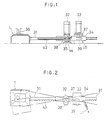
- the aforesaid feeder 7 includes a feed shoe 1, which is mounted on the distal end of an arm 31, a motor 32 for linear motion, which gives advance/retreat motion to the aforesaid feed shoe 1, and a motor 33 for swinging motion, which gives left and right swinging motion to the aforesaid feed shoe 1, as shown in Figs. 1 and 2.
- a motor 32 for linear motion which gives advance/retreat motion to the aforesaid feed shoe 1
- a motor 33 for swinging motion which gives left and right swinging motion to the aforesaid feed shoe 1, as shown in Figs. 1 and 2.
- a pivot 35 stands erect at the top surface of intermediate wall 10 of the frame 5, and a casing 34 is rotatably supported by means of the pivot 35, as shown in Figs. 1 and 2.
- the feed shoe 1 has a shape just like an upside-down bowl like a conventional feed shoe, and its interior is defined so that molding powder can be stored.
- the molding powder is supplied to the interior of the feed shoe 1 through a flexible hose 36 connecting the feed shoe 1 with a hopper 30.
- a base end of the arm 31 is fixed to one side of the feed shoe 1.
- a notch is formed at one place on the side of the casing 34 so that the rack gear 43 of the arm 31 inserted in the casing 34 is exposed.
- the motor 32 for linear motion is installed on the top surface of the casing 34 in the vicinity of the portion where the aforesaid notch is formed so that an output shaft 44 of the motor is directed downward.
- a pinion gear 38 which is fixed to the distal end of the output shaft 44, engages with the rack gear 43 of the arm 31 inserted in the casing 34 through the aforesaid notch. Therefore, when the motor for linear motion is rotated in the normal or reverse direction, the arm 31 is projected or retracted from the casing 34.
- a gate-shaped mounting base 37 for installing the motor 33 for swinging motion is mounted on the top surface of the intermediate wall 10 of the frame 5 so that it extends over the rear portion of the casing 34.
- the motor 33 for swinging motion is installed on the aforesaid mounting base 37 so that an output shaft 45 of the motor is directed downward.
- An eccentric cam 39 fixed to the distal end of the output shaft 45 is arranged so as to abut on a side face of the casing 34.
- the position at which the casing 34 abuts on the eccentric cam 39 is a short distance away from the pivot 35 rotatably supporting the casing 34 towards the reverse side of the feed-shoe side.
- Upper and lower punches 13 and 14 which are selected in accordance with a desired molded product, are attached to the distal end of the ball-bearing screw 12 for driving the upper punch and to that of the ball-bearing screw 15 for driving the lower punch, respectively.
- the die 2 corresponding to these upper and lower punches 13 and 14 is fitted into the die mounting portion 26 of the intermediate wall 10 of the frame 5, and is fixed so that the top surface of the die is flush with the top surface of the plate 27.
- the upper punch 13 is situated at the retreat position above and away from the die 2 before the powder molding machine is operated.
- the lower punch 14 is situated in a predetermined position located in the die space 28 penetrating through the center of the die 2, from below, thus defining the molding space 3 (cavity) by the die 2 and the lower punch 14.
- the feed shoe 1 of the feeder 7 is situated at the retreat position (shown by the broken line in Fig. 4) away from the die 2, and molding powder is supplied to the interior of the feed shoe from the hopper 30 through the flexible hose 36.
- the eccentric cam 39 is situated at the neutral position, that is, the arm 31 is in a state in which it is not inclined towards either left or right direction.
- the NC unit 8 controls the drive by each of servo motors 17 and 19 of the powder molding machine 4, the motor 32 for linear motion, and the motor 33 for swinging motion according to the specified machining programs and various data previously inputted.
- the motor 32 for linear motion is first driven in the normal direction. Then, the arm 31 fixing the feed shoe 1 is moved forward with respect to the casing 34 by engagement of the pinion gear 38 attached to the distal end of the output shaft 44 of the motor 32 for linear motion with the rack gear 43 formed in the arm 31. In other words, the feed shoe 1 is moved so that it advances toward the molding space 3 from the initial retreat position.
- the motor 33 for swinging motion is not driven, so that the advancing motion of the feed shoe 1 becomes motion along the straight line.
- the casing 34 is kept in a state in which it is inclined to neither left nor right direction by the elastic force of the spring 41 and the contact with the eccentric cam 39.
- the feed shoe 1 is moved on the plate 27 until reaching the overhead position of the molding space 3 defined by the die 2 and the lower punch 14, the molding powder stored in the interior of the feed shoe 1 is dropped into the molding space 3, thereby filling the molding space 3 with the molding powder.
- the motor 33 for swinging motion is driven as long as the retreating feed shoe 1 overlaps even partially with the molding space 3.
- the position where a drive of the motor 33 for swinging motion is stopped may be set by locating a limit switch (not shown) in a predetermined position, or may be the same as the position where the motor 33 for linear motion is stopped. It is necessary, however, for the motor 33 for swinging motion to be set to stop at the point at which the eccentric cam 39 comes to rest at its neutral position.
- the motor 32 for linear motion is stopped.
- the position where the feed shoe 1 is stopped is set by locating a limit switch (not shown) on a predetermined position in the intermediate wall 10 of the frame 5. In this case, a position where the feed shoe 1 does not interfere with a subsequent punch pressing operation is selected as the aforesaid stop position of the feed shoe.
- the powder filled in the molding space undergoes a compression molding operation according to the ordinary method. More specifically, when the servo motor 17 for driving the upper punch is rotated in the normal direction, the upper ball-bearing nut 16 is rotated through the driving pulley 21, timing belt 22, and driven pulley 20. Then, the ball-bearing screw 12 for driving the upper punch is caused to come down by the rotation of the upper ball-bearing nut 16, by which the upper punch 13 attached to the distal end of the ball-bearing screw 12 is inserted into the molding space 3 to press the molding powder filled in the molding space 3.
- the servo motor 19 for driving the lower punch is simultaneously driven in the normal direction, by which the lower ball-bearing nut 18 is rotated through the driving pulley 24, timing belt 25, and driven pulley 23 to cause the ball-bearing screw 15 for driving the lower punch to be lifted.
- the molding powder filled in the molding space 3 is pressed from above and below by means of the upper and lower punches 13 and 14. Therefore, a large pressing force can be provided, and the portion where the density of the pressed powder is relatively low can be set to the middle portion in the up-and-down direction.
- the pressing operation described above may be carried out by only the descending linear motion of the ball-bearing screw 12 for driving the upper punch under the condition that the servo motor 19 for driving the lower punch is locked by means of a solenoid brake or the like.
- the NC unit 8 controls the command supplied to the servo motors 17 and 19 on the basis of the aforesaid feedback signal, and keeps the pressing force at a preset value.
- the servo motors 17 and 19 for driving the upper and lower punches will be stopped, thereby releasing the molded product from the pressing force applied.
- the servo motor 19 for driving the lower punch is driven in the reverse direction, while the servo motor 17 for driving the upper punch is driven in the normal direction. Descending motion of the ball-bearing screw 15 for driving the lower punch and that of the ball-bearing screw 12 for driving the upper punch take place at equal speeds.
- the servo motor 19 for driving the lower punch is stopped, while the servo motor 17 for driving the upper punch is driven in the reverse direction. Simultaneously, the molded product ejecting unit 46 is driven to eject the molded product laid on the lower punch 14 into the chute 42, thereby enabling the molded product to be taken out of the powder molding machine 4. Further, the servo motor 17 for driving the upper punch is driven in the reverse direction and a drive of the servo motor 19 for driving the lower punch is driven in the normal direction, whereby the upper and lower punches 13 and 14 are returned to the aforesaid initial position to complete one cycle of the molding operation.
- the feed shoe is moved to the overhead position of the die cavity from the retreat position, and the feed shoe is retreated toward the aforesaid retreat position while being swung in left and right directions as it moved toward the aforesaid retreat position
- two motors 32 and 33 which function as linear driving means and swing driving means, casing 34, base 37, eccentric cam 39, arm 31 with a rack, and the like; however, all the operations of the feed shoe to take place on the plate 27 may be replaced by the operations of a robot's hand.
- a water-atomized iron powder (apparent density of 2.93 Mg.m -3 ) was mixed with lead stearate of 1% by weight as a lubricant by means of a rolling mill for half an hour to prepare a mixture (with apparent density of 3.24 Mg.m -3 and particle size of 70 to 100 ⁇ m) for use in the test.
- a die cavity to be filled with the powder was of square shape with equal sides of 70 mm (with corner R of 5 mm) and depth of 1 mm.
- a linear speed in the directions of advancing and retreating of the feed shoe was set to 150 mm/sec.
- a swinging motion of the feed shoe for obtaining the result of filling in the case (B) was performed for every 5 mm of retreating motion, with 18 mm of amplitude of that swinging motion set.
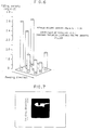
- Figs. 6 and 8 are bar graphs showing average density at each of nine different portions divided (3 times 3 makes 9) in the powder filled into the cavity in the cases of (A) and (B). Comparing these bar graphs, it can be seen that dispersion of filling density in the cavity in the filling result of case (B) was less than that of the filling result of case (A). In addition, the general average of the density of the filled powder in the case (B) was higher than that of the filled powder in the case (A).
- Figs. 7 and 9 show appearance of each of pressed powder representing the filled results of case (A) and case (B).
- the portion located at the level about 2/3 in the cavity viewed from the advancing direction of the feed shoe is blank, indicating that the blank portion is poorly filled portion.
- a striped pattern caused by the swinging operation of the feed shoe can be recognized, but the blank portion, as shown in Fig. 7 does not appear therein. This means that filling has been done evenly.
Landscapes
- Engineering & Computer Science (AREA)
- Mechanical Engineering (AREA)
- Powder Metallurgy (AREA)
- Press-Shaping Or Shaping Using Conveyers (AREA)
Abstract
Description
- The present invention relates to the improvement of a feeder and the improvement of a method for filling molding materials into a cavity in a powder molding machine designed to press molding powder supplied into a molding space (cavity) in a die by a punch to produce molded products.
- A powder molding machine, as shown in Fig. 5, forcibly presses molding powder filled into a molding space (cavity) 3 of a die 2 by a punch (only a
lower punch 14 is shown in Fig. 5), thus producing molded products. Afeed shoe 1 is used for filling the molding powder into theaforesaid molding space 3. - The die 2 is usually mounted on a
plate 27 having a flat surface so that the top surface of the die becomes flush with that of the plate. Thefeed shoe 1 is linearly reciprocated in the front and rear direction while sliding on theaforesaid plate 27. As seen from the cross-sectional view shown in Fig. 5, thefeed shoe 1, having a shape just like that of an upside-down bowl, stores molding powder in its interior, and drops the molding powder stored in the interior into themolding space 3 of the die 2 as the feed shoe advances. The molding powder is always supplied from a hopper (not shown) located above thefeed shoe 1 through aflexible hose 36. - After the
feed shoe 1 is advanced to supply the molding powder s into themolding space 3 of the die, and is then retreated from themolding space 3, the surface of molding powders filled in themolding space 3 of the die becomes undulate. This is because portions having high density and low density appear almost like waves in the filled powder s. This is caused by the following reason: when thefeed shoe 1 is retreated, a plurality of swirls, which rotate in a specific direction such as the moving direction of thefeed shoe 1, are made in the powder filled in the interior of thefeed shoe 1, as shown in Fig. 5, and these swirls disturb the uniformity of density of the molding powder filled in the moldinghollow space 3 of the die 2. In particular, in the case where the depth ofmolding space 3 is shallow, the powder uniformly filled is easy to be disturbed when the feed shoe is retreated. For this reason, the density of front-side portion of the powder s filled in themolding space 3 becomes low; on the other hand, the density of rear-side portion of the powder s becomes high. - As described above, if the powder filled in a state in which the density is not uniform is pressed by means of a punch, the density of molded products thus obtained has a non-uniform density, and its strength lowers.
- JP-A-63-144898 discloses a powder molding machine according to the precharacterising part of attached
claim 1, wherein the feed shoe is coupled to a reciprocative moving means for moving the feed shoe back and forth, and connecting the feed shoe to a swivelling driving means. - The aim of the present invention is to provide a powder molding machine and a method for filling a molding material into a die cavity, which is capable of improving the uniformity of the density of molding powder filling the die cavity, and of improving the strength of the eventual molded product.
- According to a first aspect of the present invention there is provided a powder molding machine wherein a plate and a die, whose top surface is flush with the top surface of said plate, are mounted on a frame, and a feed shoe is operable to slide on said plate to pass over a molding space defined in said die to cause molding material stored in said feed shoe to be dropped into said molding space, the powder molding machine further including: a linear driving means for moving said feed shoe in a direction of advancing from a retreat position to said molding space and retreating from said molding space to said retreat position; swing driving means for swinging said feed shoe in directions on each side of said direction of advancing and retreating; and a mechanism for giving said feed shoe a motion in directions caused by the combination of said linear driving means and said swing driving means when they are both in operation; characterised in that: said swing driving means is fixed to the frame of said powder molding machine to rotate a casing, supporting said feed shoe at a predetermined angle with respect to said frame, and said linear driving means is fixed to said casing to enable said feed shoe to be projected from or retracted towards said casing.
- Preferably, the powder molding machine further includes one or two or more position detecting means for detecting an arbitrary position between the retreat position and the most advanced position of the feed shoe, and transmission means for transmitting an output detected by the position detecting means to both or any one of said linear driving means and swing driving means.
- In addition, according to a second aspect of the present invention there is provided a method for filling molding materials in a die cavity of a powder molding machine, comprising the steps of:
- dropping molding materials stored in a feed shoe into a die cavity by moving the feed shoe to the overhead position of the die cavity from a retreat position; and
- swinging said feed shoe, when said feed shoe is retreating from the position of said die cavity to its retreat position, in transverse directions with respect to its retreating direction as long as at least a part of said feed shoe overlaps with said cavity.
- As described above, according to the present invention, the feed shoe passes the overhead position of the cavity, in which powder is filled, while being swung in the left and right directions when retreating, so that the uniformity of density of molding powders filled in the cavity will not be adversely affected by retreating motion of the feed shoe.
-
- Fig. 1 is a partially sectional front view of an associated mechanism of a feed shoe according to the present invention;
- Fig. 2 is a plan view of the associated mechanism of the feed shoe shown in Fig. 1;
- Fig. 3 is a partially sectional front view of the entirety of the powder molding machine;
- Fig. 4 is a view for explaining a retreating operation of the feed shoe according to the present invention;
- Fig. 5 is a cross-sectional view showing a state in which molding powders are supplied to the feed shoe by a conventional method;
- Fig. 6 is a graph illustrating density distribution when molding materials are filled in the cavity by the conventional method;
- Fig. 7 is a view showing an appearance of powder when molding materials are filled in the cavity by the conventional method;
- Fig. 8 is a graph illustrating density distribution when molding materials are filled in the cavity by the method according to the present invention; and
- Fig. 9 is a view showing an appearance of powder when molding materials are filled in the cavity by the method according to the present invention.
- A powder molding machine 4 has the configuration in which a molding device 6 and a feeder 7 are mounted on a frame 5 having a upper wall 9, an
intermediate wall 10 and alower wall 11, as shown in Fig. 3, and a drive of the machine is controlled by means of an NC unit 8. - A ball-bearing
nut 16 is rotatably installed in the upper wall 9 of the frame 5, and engages with a ball-bearingscrew 12 for driving an upper punch. A ball-bearingnut 18 is rotatably installed in thelower wall 11 of the frame 5, and engages with a ball-bearingscrew 15 for driving a lower punch. In addition, the center of each of these ball-bearingscrews - A
die mounting portion 26 with step, which has an opening penetrating in the up-and-down direction, and is coaxial with the aforesaid axis a, is formed in theintermediate wall 10 of the frame 5. The die 2 is mounted on thedie mounting portion 26, and is fixed on theintermediate wall 10 by means of theplate 27. The top surface of the die 2 thus mounted is aligned with the top surface of theplate 27. The opening space penetrating in the up-and-down direction is constituted so that the upper punch 13 attached to the distal end of the ball-bearing screw for driving the upper punch, and thelower punch 14 attached to the distal end of the ball-bearingscrew 15 for driving the lower punch, are inserted into the space from above and below, respectively. - The ball-bearing
nut 16 mounted on the upper wall 9 of the frame 5 is rotated by means of a drive of aservo motor 17 mounted on the upper wall 9 through adriving pulley 21 fixed on an output shaft of theservo motor 17, and atiming belt 22 wound around a drivenpulley 20 fixed on the ball-bearingnut 16 and theaforesaid driving pulley 21. The ball-bearingnut 18 mounted on thelower wall 11 of the frame 5 is rotated by means of a drive of aservo motor 19 mounted on thelower wall 11 through adriving pulley 24 fixed on an output shaft of theservo motor 19, and atiming belt 25 wound around a drivenpulley 23 fixed on the ball-bearingnut 18 and theaforesaid driving pulley 24. - When the upper and lower ball-bearing
nuts servo motors screws lower punches 13 and 14 being moved in a space of the die 2. - The molding device 6 comprises the upper and lower ball-bearing
nuts screws lower punches 13 and 14, andservo motors - The NC unit 8 executes general operational sequence control of the molding powder machine, and molding program control according to inputted programs and data. Incidentally, a
load cell 29 is installed in the lower ball-bearingnut 18 to detect the actual pressing force of upper and lower punches which is applied to the molding powder supplied into the space of die. The detected output data is fed back to the NC unit 8. - A
hopper 30 for temporarily storing powdered molding materials is mounted on the upper wall 9 of the frame 5. A feeder 7 for filling the molding materials into the die cavity is installed in theintermediate wall 10. The details of the feed 7 will be explained later. - In Fig. 3, the
reference numeral 46 denotes an ejecting unit for ejecting molded products by an action of solenoid, and thereference numeral 47 denotes a chute for receiving the molded products ejected by theaforesaid ejecting unit 46 from thelower punch 14. - The powder molding machine 4 described above with reference to Fig. 3 has the known constitution as disclosed in Japanese Patent Laid-open Publication No. Hei 1-181997, for example.
- In an embodiment according to the present invention, the aforesaid feeder 7 includes a
feed shoe 1, which is mounted on the distal end of anarm 31, amotor 32 for linear motion, which gives advance/retreat motion to theaforesaid feed shoe 1, and amotor 33 for swinging motion, which gives left and right swinging motion to theaforesaid feed shoe 1, as shown in Figs. 1 and 2. The details of the configuration will be described below. - A
pivot 35 stands erect at the top surface ofintermediate wall 10 of the frame 5, and acasing 34 is rotatably supported by means of thepivot 35, as shown in Figs. 1 and 2. - The
feed shoe 1 has a shape just like an upside-down bowl like a conventional feed shoe, and its interior is defined so that molding powder can be stored. The molding powder is supplied to the interior of thefeed shoe 1 through aflexible hose 36 connecting thefeed shoe 1 with ahopper 30. A base end of thearm 31 is fixed to one side of thefeed shoe 1. - The
arm 31, which has arack gear 43 formed on one side of thearm 31 over almost the entire length thereof, is inserted into theaforesaid casing 34. A notch is formed at one place on the side of thecasing 34 so that therack gear 43 of thearm 31 inserted in thecasing 34 is exposed. Themotor 32 for linear motion is installed on the top surface of thecasing 34 in the vicinity of the portion where the aforesaid notch is formed so that anoutput shaft 44 of the motor is directed downward. Apinion gear 38, which is fixed to the distal end of theoutput shaft 44, engages with therack gear 43 of thearm 31 inserted in thecasing 34 through the aforesaid notch. Therefore, when the motor for linear motion is rotated in the normal or reverse direction, thearm 31 is projected or retracted from thecasing 34. - A gate-
shaped mounting base 37 for installing themotor 33 for swinging motion is mounted on the top surface of theintermediate wall 10 of the frame 5 so that it extends over the rear portion of thecasing 34. Themotor 33 for swinging motion is installed on theaforesaid mounting base 37 so that anoutput shaft 45 of the motor is directed downward. Aneccentric cam 39 fixed to the distal end of theoutput shaft 45 is arranged so as to abut on a side face of thecasing 34. The position at which thecasing 34 abuts on theeccentric cam 39 is a short distance away from thepivot 35 rotatably supporting thecasing 34 towards the reverse side of the feed-shoe side. Therefore, when themotor 33 for swinging motion is driven with respect to thecasing 34 supported by thepivot 35, thecasing 34 is pressed by rotation of theeccentric cam 39, and is swung at a predetermined angle with thepivot 35 being the central axis. Besides, an attracting spring 41, whose one and the other ends are fixed to thecasing 34 and theintermediate wall 10, respectively, is used for always keeping the side face of thecasing 34 in contact with theeccentric cam 39. - A molding operation of a powder molding machine according to an embodiment of the present invention will be described below.
- Upper and
lower punches 13 and 14, which are selected in accordance with a desired molded product, are attached to the distal end of the ball-bearingscrew 12 for driving the upper punch and to that of the ball-bearingscrew 15 for driving the lower punch, respectively. The die 2 corresponding to these upper andlower punches 13 and 14 is fitted into thedie mounting portion 26 of theintermediate wall 10 of the frame 5, and is fixed so that the top surface of the die is flush with the top surface of theplate 27. - Also, the upper punch 13 is situated at the retreat position above and away from the die 2 before the powder molding machine is operated. On the other hand, the
lower punch 14 is situated in a predetermined position located in thedie space 28 penetrating through the center of the die 2, from below, thus defining the molding space 3 (cavity) by the die 2 and thelower punch 14. Thefeed shoe 1 of the feeder 7 is situated at the retreat position (shown by the broken line in Fig. 4) away from the die 2, and molding powder is supplied to the interior of the feed shoe from thehopper 30 through theflexible hose 36. Theeccentric cam 39 is situated at the neutral position, that is, thearm 31 is in a state in which it is not inclined towards either left or right direction. - If an operation starting command is given to the NC unit 8 in the aforesaid state, the NC unit 8 controls the drive by each of
servo motors motor 32 for linear motion, and themotor 33 for swinging motion according to the specified machining programs and various data previously inputted. - When the operation starting command is given to the NC unit 8 in the state as described above, the
motor 32 for linear motion is first driven in the normal direction. Then, thearm 31 fixing thefeed shoe 1 is moved forward with respect to thecasing 34 by engagement of thepinion gear 38 attached to the distal end of theoutput shaft 44 of themotor 32 for linear motion with therack gear 43 formed in thearm 31. In other words, thefeed shoe 1 is moved so that it advances toward themolding space 3 from the initial retreat position. - During advancing motion of the
feed shoe 1, themotor 33 for swinging motion is not driven, so that the advancing motion of thefeed shoe 1 becomes motion along the straight line. Thecasing 34 is kept in a state in which it is inclined to neither left nor right direction by the elastic force of the spring 41 and the contact with theeccentric cam 39. - Further, when the
feed shoe 1 is moved on theplate 27 until reaching the overhead position of themolding space 3 defined by the die 2 and thelower punch 14, the molding powder stored in the interior of thefeed shoe 1 is dropped into themolding space 3, thereby filling themolding space 3 with the molding powder. - Next, when the
motor 32 for linear motion is driven in the reverse-rotational direction, thearm 31 is retreated. In other wards, thefeed shoe 1 is moved to the initial retreat position from the overhead position of themolding space 3. During retreating motion of thefeed shoe 1, themotor 33 for swinging motion is driven. Therefore, when theeccentric cam 39 attached to the distal end of theoutput shaft 45 of themotor 33 for swinging motion is rotated, thecasing 34 with the retreatingarm 31 retracted thereinto is swung in left and right direction at a predetermined angle against elastic force of the spring 41. - When the
feed shoe 1 passes through the overhead position of themolding space 3 filled with the molding powder while retreating, thefeed shoe 1 is moved while swinging in the left and right direction, as indicated by a moving locus of an arbitrary point in thefeed shoe 1 shown in a plane view of Fig. 4. Thus, it can be prevented that the density of the molding powder filled in thespace 3 of the die is made uneven due to the retreating motion of thefeed shoe 1. - The
motor 33 for swinging motion is driven as long as the retreatingfeed shoe 1 overlaps even partially with themolding space 3. The position where a drive of themotor 33 for swinging motion is stopped may be set by locating a limit switch (not shown) in a predetermined position, or may be the same as the position where themotor 33 for linear motion is stopped. It is necessary, however, for themotor 33 for swinging motion to be set to stop at the point at which theeccentric cam 39 comes to rest at its neutral position. - When the
feed shoe 1 reaches the initial retreat position, themotor 32 for linear motion is stopped. The position where thefeed shoe 1 is stopped is set by locating a limit switch (not shown) on a predetermined position in theintermediate wall 10 of the frame 5. In this case, a position where thefeed shoe 1 does not interfere with a subsequent punch pressing operation is selected as the aforesaid stop position of the feed shoe. - After that, the powder filled in the molding space undergoes a compression molding operation according to the ordinary method. More specifically, when the
servo motor 17 for driving the upper punch is rotated in the normal direction, the upper ball-bearingnut 16 is rotated through the drivingpulley 21,timing belt 22, and drivenpulley 20. Then, the ball-bearingscrew 12 for driving the upper punch is caused to come down by the rotation of the upper ball-bearingnut 16, by which the upper punch 13 attached to the distal end of the ball-bearingscrew 12 is inserted into themolding space 3 to press the molding powder filled in themolding space 3. In this case, theservo motor 19 for driving the lower punch is simultaneously driven in the normal direction, by which the lower ball-bearingnut 18 is rotated through the drivingpulley 24,timing belt 25, and drivenpulley 23 to cause the ball-bearingscrew 15 for driving the lower punch to be lifted. - In this manner, the molding powder filled in the
molding space 3 is pressed from above and below by means of the upper andlower punches 13 and 14. Therefore, a large pressing force can be provided, and the portion where the density of the pressed powder is relatively low can be set to the middle portion in the up-and-down direction. However, in the case where there is no need of a large pressing force, a molded product with a small thickness is required, or the like, the pressing operation described above may be carried out by only the descending linear motion of the ball-bearingscrew 12 for driving the upper punch under the condition that theservo motor 19 for driving the lower punch is locked by means of a solenoid brake or the like. - Pressing force generated by descending linear motion of the ball-bearing
screw 12 for driving the upper punch, or by the combination of descending linear motion of the ball-bearingscrew 12 for driving the upper punch and ascending linear motion of the ball-bearingscrew 15 for driving the lower punch, is detected by means of theload cell 29 mounted on the lower ball-bearingnut 18, and is inputted to the NC unit 8 as a feedback signal. - The NC unit 8 controls the command supplied to the
servo motors servo motors servo motor 19 for driving the lower punch is driven in the reverse direction, while theservo motor 17 for driving the upper punch is driven in the normal direction. Descending motion of the ball-bearingscrew 15 for driving the lower punch and that of the ball-bearingscrew 12 for driving the upper punch take place at equal speeds. This will cause the upper andlower punches 13 and 14 to come down through thedie space 28 in a state in which the interval between the both is kept constant, whereby the molded product is taken out of the die 2 in a state in which it is laid on the top surface of thelower punch 14. - When the molded product is taken out of the die 2, the
servo motor 19 for driving the lower punch is stopped, while theservo motor 17 for driving the upper punch is driven in the reverse direction. Simultaneously, the moldedproduct ejecting unit 46 is driven to eject the molded product laid on thelower punch 14 into the chute 42, thereby enabling the molded product to be taken out of the powder molding machine 4. Further, theservo motor 17 for driving the upper punch is driven in the reverse direction and a drive of theservo motor 19 for driving the lower punch is driven in the normal direction, whereby the upper andlower punches 13 and 14 are returned to the aforesaid initial position to complete one cycle of the molding operation. - As described above, in the present embodiment, to obtain the constitution in which the feed shoe is moved to the overhead position of the die cavity from the retreat position, and the feed shoe is retreated toward the aforesaid retreat position while being swung in left and right directions as it moved toward the aforesaid retreat position, used as components for the above constitution are two
motors base 37,eccentric cam 39,arm 31 with a rack, and the like; however, all the operations of the feed shoe to take place on theplate 27 may be replaced by the operations of a robot's hand. - Concerning the filling of the specific molding material, explained in the following is an example of a comparative test in which the result of filling in the case (A) where the feed shoe is first advanced straight for filling and then retreated straight, and the result of the filling in the case (B) where the feed shoe is advanced straight and retreated while being swung towards left and right directions.
- In this test, a water-atomized iron powder (apparent density of 2.93 Mg.m-3) was mixed with lead stearate of 1% by weight as a lubricant by means of a rolling mill for half an hour to prepare a mixture (with apparent density of 3.24 Mg.m-3 and particle size of 70 to 100 µm) for use in the test. A die cavity to be filled with the powder was of square shape with equal sides of 70 mm (with corner R of 5 mm) and depth of 1 mm. A linear speed in the directions of advancing and retreating of the feed shoe was set to 150 mm/sec. In addition, a swinging motion of the feed shoe for obtaining the result of filling in the case (B) was performed for every 5 mm of retreating motion, with 18 mm of amplitude of that swinging motion set.
- Figs. 6 and 8 are bar graphs showing average density at each of nine different portions divided (3
times 3 makes 9) in the powder filled into the cavity in the cases of (A) and (B). Comparing these bar graphs, it can be seen that dispersion of filling density in the cavity in the filling result of case (B) was less than that of the filling result of case (A). In addition, the general average of the density of the filled powder in the case (B) was higher than that of the filled powder in the case (A). - Figs. 7 and 9 show appearance of each of pressed powder representing the filled results of case (A) and case (B). As seen from Fig. 7, the portion located at the level about 2/3 in the cavity viewed from the advancing direction of the feed shoe is blank, indicating that the blank portion is poorly filled portion. On the other hand, in Fig. 9, when observed carefully, a striped pattern caused by the swinging operation of the feed shoe can be recognized, but the blank portion, as shown in Fig. 7 does not appear therein. This means that filling has been done evenly.
- As is obvious from this test, a better filling result can be obtained in the case where the feed shoe is retreated while being swung after it is linearly advanced to fill the molding materials in the cavity than in the case where the feed shoe is linearly retreated after it is linearly advanced to fill the molding materials in the cavity.
Claims (3)
- A powder molding machine (4) wherein a plate (27) and a die (2), whose top surface is flush with the top surface of said plate (27), are mounted on a frame (5), and a feed shoe (1) is operable to slide on said plate (27) to pass over a molding space (3) defined in said die (2) to cause molding material stored in said feed shoe (1) to be dropped into said molding space (3), the powder molding machine further including:a linear driving means (32,38) for moving said feed shoe (1) in a direction of advancing from a retreat position to said molding space (3), and retreating from said molding space (3) to said retreat position;swing driving means (33,45,39) for swinging said feed shoe (1) in directions on each side of said direction of advancing and retreating; anda mechanism for giving said feed shoe (1) a motion in directions caused by the combination of said linear driving means (32,38) and said swing driving means (33,45,39) when they are both in operation;characterised in that:said swing driving means (33,45,39) is fixed to the frame (5) of said powder molding machine (4) to rotate a casing (34), supporting said feed shoe (1), at a predetermined angle with respect to said frame (5), and said linear driving means (32,38) is fixed to said casing (34) to enable said feed shoe (1) to be projected from or retracted towards said casing (34).
- A powder molding machine (4) according to claim 1, which further includes one or two or more position detecting means for detecting an arbitrary position between the retreat position and the most advanced position of said feed shoe (1), and transmission means for transmitting an output detected by said position detecting means to both or any one of said linear driving means (32,38) and said swing driving means (33,45,39).
- A method for filling molding material in a die cavity (3) of a powder molding machine (4), comprising:dropping molding material stored in a feed shoe (1) into the die cavity (3) by moving said feed shoe (1) to the overhead position of said die cavity (3) from a retreat position; andcharacterised by:swinging said feed shoe (1), when said feed shoe (1) is retreating from the position of said die cavity (3) to its retreat position, in transverse directions with respect to its retreating direction as long as at least a part of said feed shoe (1) overlaps with said cavity (3).
Applications Claiming Priority (3)
| Application Number | Priority Date | Filing Date | Title |
|---|---|---|---|
| JP212267/92 | 1992-07-17 | ||
| JP4212267A JPH0631491A (en) | 1992-07-17 | 1992-07-17 | Powder molding machine |
| PCT/JP1993/000994 WO1994002307A1 (en) | 1992-07-17 | 1993-07-16 | Powder molding machine and method of packing molding material into die cavity of powder molding machine |
Publications (3)
| Publication Number | Publication Date |
|---|---|
| EP0607454A1 EP0607454A1 (en) | 1994-07-27 |
| EP0607454A4 EP0607454A4 (en) | 1995-02-01 |
| EP0607454B1 true EP0607454B1 (en) | 1997-02-26 |
Family
ID=16619758
Family Applications (1)
| Application Number | Title | Priority Date | Filing Date |
|---|---|---|---|
| EP93914999A Expired - Lifetime EP0607454B1 (en) | 1992-07-17 | 1993-07-16 | Powder molding machine and method of packing molding material into die cavity of powder molding machine |
Country Status (6)
| Country | Link |
|---|---|
| US (1) | US5647410A (en) |
| EP (1) | EP0607454B1 (en) |
| JP (1) | JPH0631491A (en) |
| KR (1) | KR0158246B1 (en) |
| DE (1) | DE69308285T2 (en) |
| WO (1) | WO1994002307A1 (en) |
Families Citing this family (13)
| Publication number | Priority date | Publication date | Assignee | Title |
|---|---|---|---|---|
| JP4093379B2 (en) * | 1996-05-21 | 2008-06-04 | 蛇の目ミシン工業株式会社 | Electric press |
| DE19903417B4 (en) * | 1999-01-29 | 2007-03-29 | Wilhelm Fette Gmbh | Method for filling a hydraulic press with powders |
| JP3780842B2 (en) * | 2000-12-04 | 2006-05-31 | 株式会社村田製作所 | Powder molding apparatus and powder molding method |
| CN1974169B (en) * | 2001-02-05 | 2012-02-29 | 3Dm全球有限公司 | Plastic composite article |
| JP4522621B2 (en) * | 2001-08-31 | 2010-08-11 | 日本ピストンリング株式会社 | Multi-layer powder molding apparatus and method for producing multi-layer green compact |
| KR20030087670A (en) * | 2002-05-09 | 2003-11-15 | (주)다사테크 | Noncontacting Power supply unit of Rotating machine |
| FR2862893B1 (en) * | 2003-11-28 | 2006-02-24 | Commissariat Energie Atomique | DEVICE FOR FILLING A MOLD WITH A POWDER OR A MIXTURE OF POWDERS |
| JP2005249032A (en) * | 2004-03-03 | 2005-09-15 | Nisshinbo Ind Inc | Method and apparatus for scraping powdery body |
| JP2006343299A (en) * | 2005-05-12 | 2006-12-21 | Uniflows Co Ltd | Liquid feeder |
| JP4725722B2 (en) * | 2005-08-04 | 2011-07-13 | トヨタ自動車株式会社 | Powder input method |
| DE102011007728A1 (en) * | 2011-04-20 | 2012-10-25 | Hilti Aktiengesellschaft | Apparatus and method for producing a green compact from a powdery or granular material |
| CN104786547B (en) * | 2015-04-23 | 2017-08-04 | 东莞市宏康机械有限公司 | A kind of powder former |
| US20180339622A1 (en) * | 2015-05-06 | 2018-11-29 | Schukra Gerätebau Gmbh | System and method of controlling fibers in a mold |
Family Cites Families (12)
| Publication number | Priority date | Publication date | Assignee | Title |
|---|---|---|---|---|
| DE527766C (en) * | 1927-02-12 | 1931-06-22 | Johann Peter Spengler | Filling device for turntable presses with a filling box moving back and forth over the press molds |
| US3107702A (en) * | 1960-10-14 | 1963-10-22 | Procter & Gamble | Controlled volumetric filling of granular product into continuously moving pockets |
| SE339082B (en) * | 1968-10-02 | 1971-09-27 | Mannesmann Meer Ag | |
| JPS5618450B2 (en) * | 1973-07-06 | 1981-04-28 | ||
| US3877862A (en) * | 1973-11-16 | 1975-04-15 | Pennwalt Corp | Feeder for multi-cavity compression molding apparatus |
| JPS63144898A (en) * | 1986-12-09 | 1988-06-17 | Hitachi Electronics Eng Co Ltd | Weighing and molding device |
| CH671628A5 (en) * | 1987-02-20 | 1989-09-15 | Sig Schweiz Industrieges | |
| DE3833885A1 (en) * | 1988-10-05 | 1990-04-12 | Leifeld & Lemke Maschf | DEVICE FOR CLEANING AND FILLING CONTAINERS, ESPECIALLY BARRELS LIKE KEGS |
| JPH02160198A (en) * | 1988-12-13 | 1990-06-20 | Yoshitsuka Seiki:Kk | Powder feeding method for powder molding press |
| US4913129A (en) * | 1989-05-22 | 1990-04-03 | Bechtel Group, Inc. | Solar receiver having wind loss protection |
| DE3916951A1 (en) * | 1989-05-24 | 1990-11-29 | Graebener Theodor Pressensyst | FILLING DEVICE FOR AUTOMATICALLY FILLING THE MATRIX OF POWDER PRESSES |
| US5320146A (en) * | 1993-01-26 | 1994-06-14 | R. A. Jones & Co. Inc. | Volumetric feeder with belt gate |
-
1992
- 1992-07-17 JP JP4212267A patent/JPH0631491A/en active Pending
-
1993
- 1993-07-16 KR KR1019940700858A patent/KR0158246B1/en not_active Expired - Fee Related
- 1993-07-16 WO PCT/JP1993/000994 patent/WO1994002307A1/en not_active Ceased
- 1993-07-16 DE DE69308285T patent/DE69308285T2/en not_active Expired - Fee Related
- 1993-07-16 EP EP93914999A patent/EP0607454B1/en not_active Expired - Lifetime
- 1993-07-16 US US08/211,001 patent/US5647410A/en not_active Expired - Fee Related
Also Published As
| Publication number | Publication date |
|---|---|
| DE69308285D1 (en) | 1997-04-03 |
| EP0607454A1 (en) | 1994-07-27 |
| EP0607454A4 (en) | 1995-02-01 |
| DE69308285T2 (en) | 1997-06-05 |
| JPH0631491A (en) | 1994-02-08 |
| WO1994002307A1 (en) | 1994-02-03 |
| US5647410A (en) | 1997-07-15 |
| KR0158246B1 (en) | 1999-01-15 |
Similar Documents
| Publication | Publication Date | Title |
|---|---|---|
| EP0607454A1 (en) | Powder molding machine and method of packing molding material into die cavity of powder molding machine | |
| JP4331793B2 (en) | Equipment for producing molded bodies | |
| JPS5976231A (en) | Filler for introducing granular synthetic resin to injection molding machine | |
| JP2519498B2 (en) | Electric powder molding machine | |
| DE68925820T2 (en) | Single belt forming device | |
| US5030080A (en) | Resin material supply apparatus to resin press molding machine | |
| US5686118A (en) | Apparatus for compressing-forming powder | |
| CA1061090A (en) | Wire feeding apparatus | |
| CN114102099B (en) | Primer press-fitting system and primer press-fitting method | |
| CN214566275U (en) | Feeding device for velvet material automatic filling and pressing forming machine | |
| US4003498A (en) | Method and apparatus for controlled feeding of friction material | |
| JPH06210495A (en) | Powder feeder | |
| CA2061667A1 (en) | Rotary press | |
| CN112959728A (en) | Automatic filling and pressing forming machine for velvet materials | |
| JPH06210496A (en) | Powder feeding device and method | |
| JP2920128B1 (en) | Rotary powder compression molding machine | |
| CN221092858U (en) | Multi-machine feeding device for drum brake pads | |
| JP2823866B2 (en) | Scrap cutting equipment | |
| CN121156583B (en) | A flux loading device for hardfacing flux-cored welding wire processing | |
| JPS6235851B2 (en) | ||
| JPS6340842B2 (en) | ||
| JPH07195199A (en) | Powder molding machine | |
| JPH0665607A (en) | Method for paying out molded body in powder compression molding machine and apparatus used for the method | |
| CN214056567U (en) | Molding device for pressing powder into preset shape | |
| CN211578573U (en) | Magnetic core forming device |
Legal Events
| Date | Code | Title | Description |
|---|---|---|---|
| PUAI | Public reference made under article 153(3) epc to a published international application that has entered the european phase |
Free format text: ORIGINAL CODE: 0009012 |
|
| 17P | Request for examination filed |
Effective date: 19940413 |
|
| AK | Designated contracting states |
Kind code of ref document: A1 Designated state(s): DE GB IT |
|
| A4 | Supplementary search report drawn up and despatched | ||
| AK | Designated contracting states |
Kind code of ref document: A4 Designated state(s): DE GB IT |
|
| 17Q | First examination report despatched |
Effective date: 19951222 |
|
| GRAG | Despatch of communication of intention to grant |
Free format text: ORIGINAL CODE: EPIDOS AGRA |
|
| RAP1 | Party data changed (applicant data changed or rights of an application transferred) |
Owner name: FANUC LTD |
|
| GRAH | Despatch of communication of intention to grant a patent |
Free format text: ORIGINAL CODE: EPIDOS IGRA |
|
| GRAH | Despatch of communication of intention to grant a patent |
Free format text: ORIGINAL CODE: EPIDOS IGRA |
|
| GRAA | (expected) grant |
Free format text: ORIGINAL CODE: 0009210 |
|
| AK | Designated contracting states |
Kind code of ref document: B1 Designated state(s): DE GB IT |
|
| PG25 | Lapsed in a contracting state [announced via postgrant information from national office to epo] |
Ref country code: IT Free format text: LAPSE BECAUSE OF FAILURE TO SUBMIT A TRANSLATION OF THE DESCRIPTION OR TO PAY THE FEE WITHIN THE PRE;WARNING: LAPSES OF ITALIAN PATENTS WITH EFFECTIVE DATE BEFORE 2007 MAY HAVE OCCURRED AT ANY TIME BEFORE 2007. THE CORRECT EFFECTIVE DATE MAY BE DIFFERENT FROM THE ONE RECORDED.SCRIBED TIME-LIMIT Effective date: 19970226 |
|
| REF | Corresponds to: |
Ref document number: 69308285 Country of ref document: DE Date of ref document: 19970403 |
|
| PG25 | Lapsed in a contracting state [announced via postgrant information from national office to epo] |
Ref country code: GB Free format text: LAPSE BECAUSE OF NON-PAYMENT OF DUE FEES Effective date: 19970716 |
|
| PLBE | No opposition filed within time limit |
Free format text: ORIGINAL CODE: 0009261 |
|
| STAA | Information on the status of an ep patent application or granted ep patent |
Free format text: STATUS: NO OPPOSITION FILED WITHIN TIME LIMIT |
|
| 26N | No opposition filed | ||
| GBPC | Gb: european patent ceased through non-payment of renewal fee |
Effective date: 19970716 |
|
| PGFP | Annual fee paid to national office [announced via postgrant information from national office to epo] |
Ref country code: DE Payment date: 19990716 Year of fee payment: 7 |
|
| PG25 | Lapsed in a contracting state [announced via postgrant information from national office to epo] |
Ref country code: DE Free format text: LAPSE BECAUSE OF NON-PAYMENT OF DUE FEES Effective date: 20010501 |