EP0607320B1 - Fluid pump with magnetically levitated impeller - Google Patents
Fluid pump with magnetically levitated impeller Download PDFInfo
- Publication number
- EP0607320B1 EP0607320B1 EP92922006A EP92922006A EP0607320B1 EP 0607320 B1 EP0607320 B1 EP 0607320B1 EP 92922006 A EP92922006 A EP 92922006A EP 92922006 A EP92922006 A EP 92922006A EP 0607320 B1 EP0607320 B1 EP 0607320B1
- Authority
- EP
- European Patent Office
- Prior art keywords
- impeller
- fluid
- pumping chamber
- forces
- opposed
- Prior art date
- Legal status (The legal status is an assumption and is not a legal conclusion. Google has not performed a legal analysis and makes no representation as to the accuracy of the status listed.)
- Expired - Lifetime
Links
- 239000012530 fluid Substances 0.000 title claims abstract description 136
- 238000005086 pumping Methods 0.000 claims abstract description 65
- 238000007599 discharging Methods 0.000 claims description 10
- 230000002093 peripheral effect Effects 0.000 claims description 10
- 230000000087 stabilizing effect Effects 0.000 claims description 4
- 238000000034 method Methods 0.000 claims description 2
- 238000005339 levitation Methods 0.000 abstract description 26
- 230000007246 mechanism Effects 0.000 abstract description 8
- 239000008280 blood Substances 0.000 abstract description 7
- 210000004369 blood Anatomy 0.000 abstract description 7
- 238000006073 displacement reaction Methods 0.000 abstract description 3
- 230000008859 change Effects 0.000 abstract description 2
- 230000006641 stabilisation Effects 0.000 description 29
- 238000011105 stabilization Methods 0.000 description 29
- 238000004804 winding Methods 0.000 description 9
- 238000004891 communication Methods 0.000 description 5
- 239000007788 liquid Substances 0.000 description 5
- 230000000541 pulsatile effect Effects 0.000 description 5
- 239000007789 gas Substances 0.000 description 4
- 239000000696 magnetic material Substances 0.000 description 3
- 239000000725 suspension Substances 0.000 description 3
- 241001465754 Metazoa Species 0.000 description 2
- 230000004913 activation Effects 0.000 description 2
- 230000002411 adverse Effects 0.000 description 2
- 230000002706 hydrostatic effect Effects 0.000 description 2
- 239000002245 particle Substances 0.000 description 2
- 239000007787 solid Substances 0.000 description 2
- VVQNEPGJFQJSBK-UHFFFAOYSA-N Methyl methacrylate Chemical compound COC(=O)C(C)=C VVQNEPGJFQJSBK-UHFFFAOYSA-N 0.000 description 1
- 230000001133 acceleration Effects 0.000 description 1
- 239000002473 artificial blood Substances 0.000 description 1
- 230000000712 assembly Effects 0.000 description 1
- 238000000429 assembly Methods 0.000 description 1
- 230000015572 biosynthetic process Effects 0.000 description 1
- 230000017531 blood circulation Effects 0.000 description 1
- 230000007423 decrease Effects 0.000 description 1
- 238000004925 denaturation Methods 0.000 description 1
- 230000036425 denaturation Effects 0.000 description 1
- 235000012489 doughnuts Nutrition 0.000 description 1
- 239000003814 drug Substances 0.000 description 1
- 230000003073 embolic effect Effects 0.000 description 1
- 230000008014 freezing Effects 0.000 description 1
- 238000007710 freezing Methods 0.000 description 1
- 239000000499 gel Substances 0.000 description 1
- 238000001727 in vivo Methods 0.000 description 1
- 230000003993 interaction Effects 0.000 description 1
- 230000007774 longterm Effects 0.000 description 1
- 239000000463 material Substances 0.000 description 1
- 238000012986 modification Methods 0.000 description 1
- 230000004048 modification Effects 0.000 description 1
- 230000001453 nonthrombogenic effect Effects 0.000 description 1
- 238000005192 partition Methods 0.000 description 1
- 230000002572 peristaltic effect Effects 0.000 description 1
- 210000002381 plasma Anatomy 0.000 description 1
- 230000037452 priming Effects 0.000 description 1
- 102000004169 proteins and genes Human genes 0.000 description 1
- 108090000623 proteins and genes Proteins 0.000 description 1
- 210000002966 serum Anatomy 0.000 description 1
- 239000002002 slurry Substances 0.000 description 1
- 239000000243 solution Substances 0.000 description 1
- 239000000126 substance Substances 0.000 description 1
- 238000006467 substitution reaction Methods 0.000 description 1
- 230000002885 thrombogenetic effect Effects 0.000 description 1
Images



Classifications
-
- F—MECHANICAL ENGINEERING; LIGHTING; HEATING; WEAPONS; BLASTING
- F04—POSITIVE - DISPLACEMENT MACHINES FOR LIQUIDS; PUMPS FOR LIQUIDS OR ELASTIC FLUIDS
- F04D—NON-POSITIVE-DISPLACEMENT PUMPS
- F04D29/00—Details, component parts, or accessories
- F04D29/04—Shafts or bearings, or assemblies thereof
- F04D29/046—Bearings
- F04D29/048—Bearings magnetic; electromagnetic
-
- A—HUMAN NECESSITIES
- A61—MEDICAL OR VETERINARY SCIENCE; HYGIENE
- A61M—DEVICES FOR INTRODUCING MEDIA INTO, OR ONTO, THE BODY; DEVICES FOR TRANSDUCING BODY MEDIA OR FOR TAKING MEDIA FROM THE BODY; DEVICES FOR PRODUCING OR ENDING SLEEP OR STUPOR
- A61M60/00—Blood pumps; Devices for mechanical circulatory actuation; Balloon pumps for circulatory assistance
- A61M60/20—Type thereof
- A61M60/205—Non-positive displacement blood pumps
- A61M60/216—Non-positive displacement blood pumps including a rotating member acting on the blood, e.g. impeller
- A61M60/221—Non-positive displacement blood pumps including a rotating member acting on the blood, e.g. impeller the blood flow through the rotating member having both radial and axial components, e.g. mixed flow pumps
-
- A—HUMAN NECESSITIES
- A61—MEDICAL OR VETERINARY SCIENCE; HYGIENE
- A61M—DEVICES FOR INTRODUCING MEDIA INTO, OR ONTO, THE BODY; DEVICES FOR TRANSDUCING BODY MEDIA OR FOR TAKING MEDIA FROM THE BODY; DEVICES FOR PRODUCING OR ENDING SLEEP OR STUPOR
- A61M60/00—Blood pumps; Devices for mechanical circulatory actuation; Balloon pumps for circulatory assistance
- A61M60/40—Details relating to driving
- A61M60/403—Details relating to driving for non-positive displacement blood pumps
- A61M60/419—Details relating to driving for non-positive displacement blood pumps the force acting on the blood contacting member being permanent magnetic, e.g. from a rotating magnetic coupling between driving and driven magnets
-
- A—HUMAN NECESSITIES
- A61—MEDICAL OR VETERINARY SCIENCE; HYGIENE
- A61M—DEVICES FOR INTRODUCING MEDIA INTO, OR ONTO, THE BODY; DEVICES FOR TRANSDUCING BODY MEDIA OR FOR TAKING MEDIA FROM THE BODY; DEVICES FOR PRODUCING OR ENDING SLEEP OR STUPOR
- A61M60/00—Blood pumps; Devices for mechanical circulatory actuation; Balloon pumps for circulatory assistance
- A61M60/40—Details relating to driving
- A61M60/403—Details relating to driving for non-positive displacement blood pumps
- A61M60/422—Details relating to driving for non-positive displacement blood pumps the force acting on the blood contacting member being electromagnetic, e.g. using canned motor pumps
-
- A—HUMAN NECESSITIES
- A61—MEDICAL OR VETERINARY SCIENCE; HYGIENE
- A61M—DEVICES FOR INTRODUCING MEDIA INTO, OR ONTO, THE BODY; DEVICES FOR TRANSDUCING BODY MEDIA OR FOR TAKING MEDIA FROM THE BODY; DEVICES FOR PRODUCING OR ENDING SLEEP OR STUPOR
- A61M60/00—Blood pumps; Devices for mechanical circulatory actuation; Balloon pumps for circulatory assistance
- A61M60/50—Details relating to control
- A61M60/508—Electronic control means, e.g. for feedback regulation
- A61M60/562—Electronic control means, e.g. for feedback regulation for making blood flow pulsatile in blood pumps that do not intrinsically create pulsatile flow
-
- A—HUMAN NECESSITIES
- A61—MEDICAL OR VETERINARY SCIENCE; HYGIENE
- A61M—DEVICES FOR INTRODUCING MEDIA INTO, OR ONTO, THE BODY; DEVICES FOR TRANSDUCING BODY MEDIA OR FOR TAKING MEDIA FROM THE BODY; DEVICES FOR PRODUCING OR ENDING SLEEP OR STUPOR
- A61M60/00—Blood pumps; Devices for mechanical circulatory actuation; Balloon pumps for circulatory assistance
- A61M60/80—Constructional details other than related to driving
- A61M60/802—Constructional details other than related to driving of non-positive displacement blood pumps
- A61M60/804—Impellers
-
- A—HUMAN NECESSITIES
- A61—MEDICAL OR VETERINARY SCIENCE; HYGIENE
- A61M—DEVICES FOR INTRODUCING MEDIA INTO, OR ONTO, THE BODY; DEVICES FOR TRANSDUCING BODY MEDIA OR FOR TAKING MEDIA FROM THE BODY; DEVICES FOR PRODUCING OR ENDING SLEEP OR STUPOR
- A61M60/00—Blood pumps; Devices for mechanical circulatory actuation; Balloon pumps for circulatory assistance
- A61M60/80—Constructional details other than related to driving
- A61M60/802—Constructional details other than related to driving of non-positive displacement blood pumps
- A61M60/818—Bearings
- A61M60/82—Magnetic bearings
- A61M60/822—Magnetic bearings specially adapted for being actively controlled
-
- A—HUMAN NECESSITIES
- A61—MEDICAL OR VETERINARY SCIENCE; HYGIENE
- A61M—DEVICES FOR INTRODUCING MEDIA INTO, OR ONTO, THE BODY; DEVICES FOR TRANSDUCING BODY MEDIA OR FOR TAKING MEDIA FROM THE BODY; DEVICES FOR PRODUCING OR ENDING SLEEP OR STUPOR
- A61M60/00—Blood pumps; Devices for mechanical circulatory actuation; Balloon pumps for circulatory assistance
- A61M60/80—Constructional details other than related to driving
- A61M60/802—Constructional details other than related to driving of non-positive displacement blood pumps
- A61M60/818—Bearings
- A61M60/824—Hydrodynamic or fluid film bearings
-
- F—MECHANICAL ENGINEERING; LIGHTING; HEATING; WEAPONS; BLASTING
- F04—POSITIVE - DISPLACEMENT MACHINES FOR LIQUIDS; PUMPS FOR LIQUIDS OR ELASTIC FLUIDS
- F04D—NON-POSITIVE-DISPLACEMENT PUMPS
- F04D13/00—Pumping installations or systems
- F04D13/02—Units comprising pumps and their driving means
- F04D13/06—Units comprising pumps and their driving means the pump being electrically driven
-
- F—MECHANICAL ENGINEERING; LIGHTING; HEATING; WEAPONS; BLASTING
- F04—POSITIVE - DISPLACEMENT MACHINES FOR LIQUIDS; PUMPS FOR LIQUIDS OR ELASTIC FLUIDS
- F04D—NON-POSITIVE-DISPLACEMENT PUMPS
- F04D13/00—Pumping installations or systems
- F04D13/02—Units comprising pumps and their driving means
- F04D13/06—Units comprising pumps and their driving means the pump being electrically driven
- F04D13/0646—Units comprising pumps and their driving means the pump being electrically driven the hollow pump or motor shaft being the conduit for the working fluid
-
- F—MECHANICAL ENGINEERING; LIGHTING; HEATING; WEAPONS; BLASTING
- F04—POSITIVE - DISPLACEMENT MACHINES FOR LIQUIDS; PUMPS FOR LIQUIDS OR ELASTIC FLUIDS
- F04D—NON-POSITIVE-DISPLACEMENT PUMPS
- F04D29/00—Details, component parts, or accessories
- F04D29/18—Rotors
- F04D29/186—Shaftless rotors
-
- F—MECHANICAL ENGINEERING; LIGHTING; HEATING; WEAPONS; BLASTING
- F04—POSITIVE - DISPLACEMENT MACHINES FOR LIQUIDS; PUMPS FOR LIQUIDS OR ELASTIC FLUIDS
- F04D—NON-POSITIVE-DISPLACEMENT PUMPS
- F04D29/00—Details, component parts, or accessories
- F04D29/40—Casings; Connections of working fluid
- F04D29/42—Casings; Connections of working fluid for radial or helico-centrifugal pumps
- F04D29/426—Casings; Connections of working fluid for radial or helico-centrifugal pumps especially adapted for liquid pumps
-
- F—MECHANICAL ENGINEERING; LIGHTING; HEATING; WEAPONS; BLASTING
- F04—POSITIVE - DISPLACEMENT MACHINES FOR LIQUIDS; PUMPS FOR LIQUIDS OR ELASTIC FLUIDS
- F04D—NON-POSITIVE-DISPLACEMENT PUMPS
- F04D29/00—Details, component parts, or accessories
- F04D29/40—Casings; Connections of working fluid
- F04D29/42—Casings; Connections of working fluid for radial or helico-centrifugal pumps
- F04D29/44—Fluid-guiding means, e.g. diffusers
- F04D29/445—Fluid-guiding means, e.g. diffusers especially adapted for liquid pumps
-
- F—MECHANICAL ENGINEERING; LIGHTING; HEATING; WEAPONS; BLASTING
- F04—POSITIVE - DISPLACEMENT MACHINES FOR LIQUIDS; PUMPS FOR LIQUIDS OR ELASTIC FLUIDS
- F04D—NON-POSITIVE-DISPLACEMENT PUMPS
- F04D5/00—Pumps with circumferential or transverse flow
- F04D5/001—Shear force pumps
-
- F—MECHANICAL ENGINEERING; LIGHTING; HEATING; WEAPONS; BLASTING
- F16—ENGINEERING ELEMENTS AND UNITS; GENERAL MEASURES FOR PRODUCING AND MAINTAINING EFFECTIVE FUNCTIONING OF MACHINES OR INSTALLATIONS; THERMAL INSULATION IN GENERAL
- F16C—SHAFTS; FLEXIBLE SHAFTS; ELEMENTS OR CRANKSHAFT MECHANISMS; ROTARY BODIES OTHER THAN GEARING ELEMENTS; BEARINGS
- F16C32/00—Bearings not otherwise provided for
- F16C32/04—Bearings not otherwise provided for using magnetic or electric supporting means
- F16C32/0406—Magnetic bearings
- F16C32/0408—Passive magnetic bearings
- F16C32/0423—Passive magnetic bearings with permanent magnets on both parts repelling each other
- F16C32/0425—Passive magnetic bearings with permanent magnets on both parts repelling each other for radial load mainly
-
- F—MECHANICAL ENGINEERING; LIGHTING; HEATING; WEAPONS; BLASTING
- F16—ENGINEERING ELEMENTS AND UNITS; GENERAL MEASURES FOR PRODUCING AND MAINTAINING EFFECTIVE FUNCTIONING OF MACHINES OR INSTALLATIONS; THERMAL INSULATION IN GENERAL
- F16C—SHAFTS; FLEXIBLE SHAFTS; ELEMENTS OR CRANKSHAFT MECHANISMS; ROTARY BODIES OTHER THAN GEARING ELEMENTS; BEARINGS
- F16C32/00—Bearings not otherwise provided for
- F16C32/04—Bearings not otherwise provided for using magnetic or electric supporting means
- F16C32/0406—Magnetic bearings
- F16C32/0408—Passive magnetic bearings
- F16C32/0423—Passive magnetic bearings with permanent magnets on both parts repelling each other
- F16C32/0427—Passive magnetic bearings with permanent magnets on both parts repelling each other for axial load mainly
-
- H—ELECTRICITY
- H02—GENERATION; CONVERSION OR DISTRIBUTION OF ELECTRIC POWER
- H02K—DYNAMO-ELECTRIC MACHINES
- H02K21/00—Synchronous motors having permanent magnets; Synchronous generators having permanent magnets
- H02K21/12—Synchronous motors having permanent magnets; Synchronous generators having permanent magnets with stationary armatures and rotating magnets
- H02K21/14—Synchronous motors having permanent magnets; Synchronous generators having permanent magnets with stationary armatures and rotating magnets with magnets rotating within the armatures
-
- H—ELECTRICITY
- H02—GENERATION; CONVERSION OR DISTRIBUTION OF ELECTRIC POWER
- H02K—DYNAMO-ELECTRIC MACHINES
- H02K7/00—Arrangements for handling mechanical energy structurally associated with dynamo-electric machines, e.g. structural association with mechanical driving motors or auxiliary dynamo-electric machines
- H02K7/08—Structural association with bearings
- H02K7/09—Structural association with bearings with magnetic bearings
-
- H—ELECTRICITY
- H02—GENERATION; CONVERSION OR DISTRIBUTION OF ELECTRIC POWER
- H02K—DYNAMO-ELECTRIC MACHINES
- H02K7/00—Arrangements for handling mechanical energy structurally associated with dynamo-electric machines, e.g. structural association with mechanical driving motors or auxiliary dynamo-electric machines
- H02K7/14—Structural association with mechanical loads, e.g. with hand-held machine tools or fans
-
- A—HUMAN NECESSITIES
- A61—MEDICAL OR VETERINARY SCIENCE; HYGIENE
- A61M—DEVICES FOR INTRODUCING MEDIA INTO, OR ONTO, THE BODY; DEVICES FOR TRANSDUCING BODY MEDIA OR FOR TAKING MEDIA FROM THE BODY; DEVICES FOR PRODUCING OR ENDING SLEEP OR STUPOR
- A61M60/00—Blood pumps; Devices for mechanical circulatory actuation; Balloon pumps for circulatory assistance
- A61M60/10—Location thereof with respect to the patient's body
- A61M60/122—Implantable pumps or pumping devices, i.e. the blood being pumped inside the patient's body
- A61M60/126—Implantable pumps or pumping devices, i.e. the blood being pumped inside the patient's body implantable via, into, inside, in line, branching on, or around a blood vessel
- A61M60/148—Implantable pumps or pumping devices, i.e. the blood being pumped inside the patient's body implantable via, into, inside, in line, branching on, or around a blood vessel in line with a blood vessel using resection or like techniques, e.g. permanent endovascular heart assist devices
-
- A—HUMAN NECESSITIES
- A61—MEDICAL OR VETERINARY SCIENCE; HYGIENE
- A61M—DEVICES FOR INTRODUCING MEDIA INTO, OR ONTO, THE BODY; DEVICES FOR TRANSDUCING BODY MEDIA OR FOR TAKING MEDIA FROM THE BODY; DEVICES FOR PRODUCING OR ENDING SLEEP OR STUPOR
- A61M60/00—Blood pumps; Devices for mechanical circulatory actuation; Balloon pumps for circulatory assistance
- A61M60/10—Location thereof with respect to the patient's body
- A61M60/122—Implantable pumps or pumping devices, i.e. the blood being pumped inside the patient's body
- A61M60/165—Implantable pumps or pumping devices, i.e. the blood being pumped inside the patient's body implantable in, on, or around the heart
- A61M60/178—Implantable pumps or pumping devices, i.e. the blood being pumped inside the patient's body implantable in, on, or around the heart drawing blood from a ventricle and returning the blood to the arterial system via a cannula external to the ventricle, e.g. left or right ventricular assist devices
-
- A—HUMAN NECESSITIES
- A61—MEDICAL OR VETERINARY SCIENCE; HYGIENE
- A61M—DEVICES FOR INTRODUCING MEDIA INTO, OR ONTO, THE BODY; DEVICES FOR TRANSDUCING BODY MEDIA OR FOR TAKING MEDIA FROM THE BODY; DEVICES FOR PRODUCING OR ENDING SLEEP OR STUPOR
- A61M60/00—Blood pumps; Devices for mechanical circulatory actuation; Balloon pumps for circulatory assistance
- A61M60/10—Location thereof with respect to the patient's body
- A61M60/122—Implantable pumps or pumping devices, i.e. the blood being pumped inside the patient's body
- A61M60/165—Implantable pumps or pumping devices, i.e. the blood being pumped inside the patient's body implantable in, on, or around the heart
- A61M60/178—Implantable pumps or pumping devices, i.e. the blood being pumped inside the patient's body implantable in, on, or around the heart drawing blood from a ventricle and returning the blood to the arterial system via a cannula external to the ventricle, e.g. left or right ventricular assist devices
- A61M60/183—Implantable pumps or pumping devices, i.e. the blood being pumped inside the patient's body implantable in, on, or around the heart drawing blood from a ventricle and returning the blood to the arterial system via a cannula external to the ventricle, e.g. left or right ventricular assist devices drawing blood from both ventricles, e.g. bi-ventricular assist devices [BiVAD]
-
- F—MECHANICAL ENGINEERING; LIGHTING; HEATING; WEAPONS; BLASTING
- F05—INDEXING SCHEMES RELATING TO ENGINES OR PUMPS IN VARIOUS SUBCLASSES OF CLASSES F01-F04
- F05B—INDEXING SCHEME RELATING TO WIND, SPRING, WEIGHT, INERTIA OR LIKE MOTORS, TO MACHINES OR ENGINES FOR LIQUIDS COVERED BY SUBCLASSES F03B, F03D AND F03G
- F05B2240/00—Components
- F05B2240/10—Stators
- F05B2240/11—Shroud seal segments
-
- F—MECHANICAL ENGINEERING; LIGHTING; HEATING; WEAPONS; BLASTING
- F05—INDEXING SCHEMES RELATING TO ENGINES OR PUMPS IN VARIOUS SUBCLASSES OF CLASSES F01-F04
- F05B—INDEXING SCHEME RELATING TO WIND, SPRING, WEIGHT, INERTIA OR LIKE MOTORS, TO MACHINES OR ENGINES FOR LIQUIDS COVERED BY SUBCLASSES F03B, F03D AND F03G
- F05B2240/00—Components
- F05B2240/50—Bearings
- F05B2240/51—Bearings magnetic
- F05B2240/515—Bearings magnetic electromagnetic
-
- Y—GENERAL TAGGING OF NEW TECHNOLOGICAL DEVELOPMENTS; GENERAL TAGGING OF CROSS-SECTIONAL TECHNOLOGIES SPANNING OVER SEVERAL SECTIONS OF THE IPC; TECHNICAL SUBJECTS COVERED BY FORMER USPC CROSS-REFERENCE ART COLLECTIONS [XRACs] AND DIGESTS
- Y10—TECHNICAL SUBJECTS COVERED BY FORMER USPC
- Y10S—TECHNICAL SUBJECTS COVERED BY FORMER USPC CROSS-REFERENCE ART COLLECTIONS [XRACs] AND DIGESTS
- Y10S415/00—Rotary kinetic fluid motors or pumps
- Y10S415/90—Rotary blood pump
Definitions
- This invention relates to a fluid pump with a rotary impeller, and more particularly to a fluid pump with a bearing-free, seal-free electromagnetically-driven rotary impeller, levitated by a combination of axial and radial localized opposed repulsive magnetic and fluid forces or by repulsive axial and radial magnetic forces only.
- a rotary pump includes a pumping chamber with inlet and outlet ports and an impeller mounted within the pumping chamber for rotation about an axis. Frequently the impeller is mounted on a shaft that extends through one or more seals and a bearing apparatus to a rotational driving mechanism outside the pumping chamber.
- Rotary pumps employing shaft-mounted impellers with shaft seals are exemplified in the following U.S. patents: Dorman et al. U.S. Pat. No. 3,608,088; Rafferty et al. U.S.
- liquid or hydrostatic bearings to reduce heat build-up and/or to dissipate heat and to reduce frictional forces in rotation of the shaft and/or impeller.
- liquid or gas is forced into narrow clearances between the shaft and various bearing assemblies or between the impeller and the impeller housing.
- the relatively thin fluid or gas films generated in these inventions are nevertheless subject to high shear forces and some incremental heat build-up.
- the following U.S. patents exemplify the use of such liquid or hydrostatic bearings: Prindle U.S. Pat. Nos. 845,816 and 888,654; Anderson U.S. Pat. No. 2,864,552; Baker et al. U.S. Pat. No. 3,122,101; and Kambe et al. U.S. Pat. No. 4,475,866.
- Olsen et al. U.S. Pat. No. 4,688,998 discloses a fluid pump with an electromagnetically driven and levitated impeller.
- a sensor and a controller is provided to sense and control the amount of electromagnetic levitating force applied to the impeller. Only electromagnetic levitating forces are applied to the impeller.
- no fluid forces are available for levitation and, moreover, the electromagnetic levitated forces are not applied to the impeller in separate and distinct axial and radial directions. Consequently, a sensor and controller is necessary to adjust levitation of the impeller, which is not necessary in the present invention. While Olsen et al.
- the invention requires cooperating electromagnetic sets, sensors, suspension circuits, and sensing circuits for continuously adjusting the position of the impeller in the pump housing.
- a rotary pump which is comprised of a housing defining a pumping chamber with one or more pumping chamber inlet ports and a pumping chamber outlet port or ports; a rotatable impeller or impellers disposed in the pumping chamber for rotation about an axis; polarized electromagnetic means for rotating the impeller about the axis; and opposed permanent magnetic means located in proximity to the impeller for levitating the impeller axially, radially or both.
- levitational forces in the other direction are provided by fluid forces conducted from the peripheral region downstream of the impeller.
- Means for conducting fluid from a high pressure area at the peripheral region of the impeller and discharging the fluid in opposed directions within a lower pressure area in general proximity to the axis of the impeller, in either an axial or radial direction, thereby levitating and stabilizing the impeller within the pumping chamber by application of both axial or radial fluid forces in combination with repulsive magnetic forces in the direction (axial or radial) not supplied by the fluid forces.
- the impeller may be fashioned of various materials, preferably non-magnetic such as methyl methacrylate.
- the impeller has an overall bulk density similar or identical to that of the fluid being pumped, thereby resulting in suspension of the impeller in the pumped fluid and facilitating levitation and stabilization of the impeller within the pumped fluid.
- the impeller may take various shapes, and may or may not have vanes, depending upon the particular pump application.
- the impeller may be solid, or may have internal fluid-filled space in communication with the pumping chamber or with the pumping chamber inlet and/or outlet ports.
- the impeller may have a single inlet or opposed inlets near the axis of the impeller communicating with the pumping chamber inlet ports, and opposed outlets at the periphery of the impeller communicating with the pumping chamber outlet port or ports.
- the impeller preferably has axially extending neck portions.
- Means for levitating the impeller comprises permanent magnets, including a centrally located magnet and a magnet or magnets surrounding the centrally located magnet spaced both axially and radially from the centrally located magnet for magnetic stabilization both axially and radially, and spaced only axially or only radially for magnetic stabilization in the axial or radial direction only.
- stabilizing forces in the other direction are provided by conduits emanating from the vicinity of the pumping chamber outlet port and terminating in various configurations generally near the axially extending neck portion of the impeller to conduct fluid forces to the impeller for impingement on the impeller.
- Magnetic stabilization or levitation is achieved by repulsive magnetic forces in balanced opposed axial and/or radial directions as a result of centrally located magnets, fixed with respect to the housing and surrounding or bracketing magnets fixed with respect to the impeller, disposed with the polarity of the centrally located magnets and the surrounding or bracketing magnets oriented to repel.
- balanced repulsive magnetic forces are essential, as opposed to balanced attractive magnetic forces, because balanced attractive forces would cause magnetic freezing of the impeller if the impeller were to be jarred out of magnetic equilibrium because magnetic forces increase as distance decreases, thereby permanently destroying magnetic equilibrium conditions, and causing the magnets to engage and freeze the impeller in the housing.
- Polarized electromagnetic means for rotating the impeller may comprise conducting wire windings within the periphery of the pump housing electromagnetically coupled to permanent magnets housed within the periphery of the impeller.
- the polarized electromagnetically means for rotating the impeller may comprise conducting wire windings housed within a stator located internal to the impeller, the stator being in structural communication with the pump housing and electromagnetically coupled to one or more magnets housed within the internal structure of the impeller.
- fluid means any aggregate of matter in which the molecules are able to flow past each other without limit and without the formation of fracture planes.
- the term includes gases, liquids, solutions, suspensions slurries and gels and includes such specific substances as blood, plasma and serum.
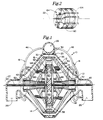
- Fig. 1 is an axial sectional view of a preferred embodiment of the present invention.
- axial levitation of the impeller is achieved by permanent repulsive magnetic forces and radial levitation is by fluid forces.
- Fig. 2 is an isolated perspective view of the permanent magnets of Fig. 1, which are used for axial levitation.
- Fig. 3 is an axial sectional view of another embodiment of the present invention.
- radial levitation is achieved by permanent repulsive magnetic forces and axial levitation is by fluid forces.
- Fig. 4 is an isolated perspective view of the permanent magnets of Fig. 3, which are used for radial levitation.
- Fig. 5 is an axial sectional view of another embodiment of the present invention.
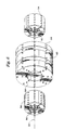
- both axial and radial levitation of the impeller is achieved by permanent magnetic repulsive forces.
- Fig. 6 is an enlarged isolated perspective view of the permanent magnets of Fig. 5, which are used for both axial and radial levitation.
- Fig. 7 is an axial sectional view of a final embodiment of the present invention.
- both axial and radial levitation is achieved by both permanent repulsive magnetic forces and by fluid forces.
- the embodiment of Fig. 7 is thus redundant in that both magnetic and fluid forces are used to levitate the impeller both axially and radially.
- Fig. 1 depicts a preferred embodiment of the pump 10 of the present invention in which axial stabilization of the impeller is achieved by repulsive magnetic forces and radial stabilization is achieved by fluid forces.
- the pump comprises a pump housing 12 defining a pumping chamber 14 through which fluid is pumped, an impeller 16, and means 18 for conducting fluid from a higher pressure region 20 near the periphery of the impeller, including pumping chamber outlet port 28, and discharging the fluid in a lower pressure region 21 in general proximity to the axis 22 of the impeller 16.
- the pump housing may be fashioned from two or more component parts secured together with fasteners.
- the pump housing 12 also defines pumping chamber inlet ports 26 and a pumping chamber outlet port 28. The embodiment depicted in Fig.
- the housing 12 could be configured, however, to define a single inlet port 26 or more than two inlet ports, and/or multiple outlet ports.
- Other configurations of pumping chamber inlet and outlet ports for various applications of this invention will be apparent to those skilled in the art.
- the periphery of the pump housing 12 incorporates electromagnetic wire windings 30 for rotating the impeller 16 about the impeller axis 22.
- electromagnetic wire windings 30 are electromagnetically coupled to permanent magnets 32 housed within and spaced about the peripheral structure of the impeller 16.
- the wire windings may alternatively be incorporated into a stator located interior to the impeller 16, and about which the impeller 16 may rotate, such as shown in Fig. 20 of U.S. Patent No. 5,055,005.
- the stator may be supported within the impeller by one or more supporting shafts disposed along the axis of rotation of the impeller, the shafts being in structural communication with the pump housing 12.
- the wire windings within the stator may be in electrical communication with one or more electrical power sources by means of wires running from the stator through the supporting shafts to one or more of such electrical power sources located within or external to the fluid pump 10.
- Other configurations of electromagnetic means for rotating the impeller about an axis will be obvious to those skilled in the art.
- the impeller 16 has axially opposed inlets 36 communicating with the pumping chamber inlet ports 26, and opposed outlets 38 at the periphery of the impeller 16 communicating with the pumping chamber 14 and thereby with the pumping chamber outlet port 28.
- fluid enters the opposed inlets 36 of the impeller 16 from the pumping chamber inlet ports 26.
- An acceleration is imparted to the fluid due to shear forces operating between the interior walls of the rotating impeller 16 and the fluid and between the molecules and particles of the fluid.
- Fluid exiting the impeller outlets 38 due to centrifugal forces operating within the accelerated fluid imparts circumferentially and radially directed fluid forces to the fluid within the pumping chamber 14.
- directed fluid forces are generated by frictional shear forces operating between the outer surfaces 40 of the impeller 16 and the fluid and between the molecules and particles of the fluid. Fluid thus enters pump 10 at inlet ports 26 and exits at outlet port 28.
- the impeller includes opposed, axially extending neck portions 42 that encompass the opposed inlets 36.
- neck portions facilitate radial, fluid-force levitation of the impeller by providing appropriately directed surfaces upon which levitating fluid forces may be directed.
- Such neck portions may be eliminated, however, by providing functionally equivalent inwardly facing surfaces for radial fluid-force levitation, such as shown in Figs. 9, 14, 19 and 20 of U.S. Patent No. 5,055,005, and they may be eliminated without substitution of a functional equivalent if magnetic forces are used for radial levitation.
- Neck portions 42 also facilitate axial, fluid-force levitation of the impeller by providing circular concave surfaces 43, shown in Fig. 3, into which the axial fluid forces may be directed.
- the total frictional force exerted by the impeller 16 on the fluid could be increased by providing additional partitions or walls within the impeller 16 transverse to the axis of rotation.
- the invention is suitable for the pumping of any fluid (liquid or gas) where the advantages of impeller levitation by localized forces are desired, and vanes and other structures designed to increase the shear forces generated by the impeller may be useful in such embodiments.
- the fluid forces generated solely through interaction of the fluid with the rotating outer surface of the impeller may be adequate for the intended purpose(s).
- the impeller 16 could be "solid," i.e., lacking an internal cavity in communication with the pumping chamber via impeller inlets and outlets.
- the impeller 16 For biological or medical applications, it would be useful, but not necessary, for the impeller 16 to be of a density similar or identical to that of the fluid being pumped. However, in any application and regardless of the density of the impeller 16, it is only necessary that the levitating forces be sufficient to counteract gravitational and inertial forces acting on the impeller 16.
- Biological and medical uses of the invention could include both human and veterinary applications. Similarly, the invention could be employed to function ex vivo (outside the body) or in vivo (inside the body), as well as in biological or non-biological and medical or non-medical uses not connected to a human or animal body.
- radial stabilization of impeller 16 is achieved by means 18 for conducting fluid from a region of higher fluid pressure 20 near the periphery of the impeller 16 and discharging in a region of lower fluid pressure 21 so as to radially stabilize the impeller 16 by levitating fluid forces.
- Means 18 is comprised of conduits 46 emanating from the pumping chamber outlet port 28.
- the configuration of the conduit/outlet port junction must be such that the tendency for fluid within the conduit to move toward, rather than away from, the higher pressure fluid flow region within the outlet port 28, in accordance with Bernoulli's Law, is overcome.
- Conduit 46 may leave the outlet port 28 at an orientation tangential to the direction of fluid flow within the outlet port in order to achieve the desired result.
- deflectors may be placed within the junction to facilitate diversion of fluid flow into the conduits 46.
- Other configurations of the conduit/outlet port junction for overcoming adverse fluid flow dynamics due to Bernoulli's Law will be apparent to those skilled in the art.
- each conduit 46 terminates in structure defining three fluid jet ports 52 within a lower fluid pressure region in the pumping chamber inlet port 26 in general proximity to the axially extending neck portion 42 of the impeller 16.
- the fluid jets emanating from three fluid jet ports 52 on both sides of the impeller 16 define a fluid plane or circle of orientation suitable to prevent the impeller 16 from moving in the radial direction, as shown in Fig. 1, so as not to touch the walls of the pump housing 12 or distal ends of the fluid jet ports 52.
- Each conduit 46 could terminate in one or more than three fluid jet ports, depending on the shape of the impeller and fluid flow dynamics in specific alternative embodiments of the invention, as shown for example in Figs. 15-17 of U.S. Patent No. 5,055,005.
- the fluid jet ports are oriented such that the levitating fluid forces are auto-adjusting. That is, a change in corrective force will be automatically or inherently incurred by any attempted displacement in location of the impeller.
- the present invention differs from the invention of the parent application (now U.S. Patent No. 5,055,005) in that impeller levitation is achieved by magnetic forces in addition to fluid forces or by magnetic forces alone, and is applicable to each of the embodiments shown in the patent, in addition to those disclosed herein.
- Magnetic forces may be used for axial stabilization, with fluid forces being used for radial stabilization, as shown in Fig. 1, magnetic forces may be used for radial stabilization with fluid forces being used for axial stabilization, as shown in Fig. 3, or magnetic forces may be used for both radial and axial stabilization, as shown in Fig. 5.
- both magnetic and fluid forces may be used for both radial and axial stabilization, which provides a redundancy to insure operation under various adverse conditions and greater stabilization forces under ordinary conditions, as shown in Fig. 7.
- Magnetic stabilization of impeller 16 in the axial direction is shown in Figs. 1 and 2, in which a donut-shaped, centrally-located, permanent magnet 60 is mounted in core 62, made of non-magnetic material, which is mounted to shaft 65, which is fixed at each end to housing 12 of pump 10. Centrally located magnet 60 is thus fixed with respect to housing 12 and is enveloped by impeller 16 and is, like impeller 16, disposed with its axis coincident with axis 22. Magnet 60 has a polarity as shown by lettering in Fig. 1, namely, its south pole is on the left, as viewed in Fig. 1, and its north pole is on the right.
- a pair of surrounding permanent magnets 64 donut shaped and corresponding in diameter to magnet 60, as mounted on each side of magnet 60 for rotation with impeller 16. Magnets 64 thus surround or bracket magnet 60 and are disposed with their polarity opposing the polarity of magnet 60 so that magnets 60 and 64 repel one another.
- impeller 16 is formed with an interior sleeve section 66, which serves as a mounting hub for rotor section 68, in which magnets 64 are embedded. Because of sleeve section 66, which extends to the outer surface of impeller 16, apertures 70 are provided in sleeve section 66 so fluid may pass from opposed inlets 36 of impeller 16, into the interior cavity thereof, and out impeller outlets 38. Impeller 16 could also be constructed without sleeve member 66 as long as a passage from inlet 36 to the interior cavity of impeller 16 is provided.
- centrally located permanent magnet 80 which is axially mounted on shaft 81, which is connected to housing 12 and is thus fixed with respect to housing 12.
- centrally located magnet 80 is formed with a polarity such that its cylindrical surface is its north pole and its central surface as its south pole.
- a surrounding cylindrical permanent magnet 82 is located concentrically about magnet 80 with its interior cylindrical surface as its north pole and its exterior cylindrical surface as its south pole. Surrounding magnet 82 is embedded in rotor 68 of non-magnetic material, which is mounted to sleeve 66 of impeller 16. Apertures 70 are provided in the embodiment of Figs. 3 and 4 for the purpose described above in connection with the embodiment of Figs. 1 and 2.
- FIG. 5 and 6 An embodiment in which impeller stabilization in both the axial and the radial directions is by repulsive permanent magnetic forces is shown in Figs. 5 and 6, in which axial stabilization is provided by magnets 60 and 64, which are identical to the embodiment of Figs. 1 and 2, and radial stabilization is provided by magnets 90 and 94 in a manner similar to the embodiment of Figs. 3 and 4, except that a pair of spaced permanent magnet sets is provided, disposed respectively at the opposed neck portions 42 of impeller 16.
- the two centrally located magnets 90 are mounted on shaft 92 with the exterior cylindrical surface as the north pole and the interior central surface as the south pole.
- the pair of cylindrical permanent magnets 94 surround each of the magnets 90 and have a south pole on the exterior cylindrical surface. The polarity of magnets 90 and 94 is therefore such that repulsive magnetic forces stabilize impeller 16 in the radial direction.
- impeller 16 is stabilized in both the axial and radial directions by repulsive forces between magnets 60 and 64 and magnets 90 and 94 respectively.
- the embodiment shown in Fig. 7 is a combination of magnetic force stabilization in both the axial and radial directions and fluid force stabilization in both the axial and radial directions. Fluid forces are directed axially in opposed directions at each end of impeller 16 at neck portion 42 from outlet 52 of conduit 46 and, similarly, radial forces are directed in opposed directions at each end of impeller 16 at neck portion 42. Radial stabilization is also achieved by the repulsive magnetic forces between magnets 90 and 94 and axial stabilization is achieved by repulsive magnetic forces between magnets 60 and 64.
- the embodiment in Fig. 7 is thus redundant in that both magnetic and fluid forces combine in both the axial and radial directions. This redundancy may be of value in obtaining increased levitational or stabilizing forces and in providing a fail safe design.
- the pump housing and its inlet and outlet ports, the impeller and its inlets and outlets, the conduits and fluid jet ports, and the vessels or other passageways leading to and from the pump housing may be primed with fluid prior to activation of the electromagnetic means for rotating the impeller.
- Fluid may be introduced into the invention at various locations from external sources. If necessary, an external pressurizing mechanism may be used to introduce an appropriate priming fluid and to expel air potentially trapped within the spaces of the invention.
- activation of the electromagnetic means may be sufficient to overcome the inertia of the impeller and to initiate rotation of the impeller. This would lead nearly immediately to generation of levitating fluid forces emanating from the fluid jet ports.
- an impeller of a density the same as, or similar to, that of the fluid, levitating fluid forces, in the embodiments of Figs. 1-4, will bring the impeller to its operating position very shortly after the activated electromagnetic means has induced the first several rotations of the impeller.
- structural constraints on displacement of the impeller from its operating position within the housing may be incorporated by those skilled in the art.
- the spacing between the conduit jet port structure and the impeller should be less than the spacing between the impeller and that portion of the housing encompassing the electromagnetic wire windings.
- the surfaces of the impeller, the structure comprising the fluid jet ports, and, if present, the arresting surfaces should be manufactured of smooth, non-magnetic materials having low coefficients of friction and low or non-thrombogenic characteristics.
- the preferred application of pumps of the present invention is in the medical field for the pumping of blood, although the invention may be used in numerous other medical and non-medical pumping applications.
- the rotary impeller 16 of the present invention is most conveniently operated in a continuous, non-pulsatile mode.
- the mode of operation may be pulsatile, or even intermittent.
- the levitating fluid jets could be operated in a continuous, pulsatile, or intermittent mode.
- the operation of the impeller and levitating fluid jets could fluctuate between continuous, pulsatile, and intermittent modes, or between any combination of these modes, depending on the structure and intended use of specific embodiments of the present invention. Appropriate modes of operation will be obvious to those skilled in the art.
Landscapes
- Engineering & Computer Science (AREA)
- Health & Medical Sciences (AREA)
- Mechanical Engineering (AREA)
- Heart & Thoracic Surgery (AREA)
- General Engineering & Computer Science (AREA)
- Public Health (AREA)
- Life Sciences & Earth Sciences (AREA)
- Cardiology (AREA)
- Veterinary Medicine (AREA)
- Anesthesiology (AREA)
- Biomedical Technology (AREA)
- Hematology (AREA)
- General Health & Medical Sciences (AREA)
- Animal Behavior & Ethology (AREA)
- Power Engineering (AREA)
- Physics & Mathematics (AREA)
- Electromagnetism (AREA)
- Fluid Mechanics (AREA)
- Structures Of Non-Positive Displacement Pumps (AREA)
- External Artificial Organs (AREA)
- Magnetic Bearings And Hydrostatic Bearings (AREA)
Abstract
Description
Claims (10)
- A fluid pump comprising:(a) a housing (10) defining a pumping chamber (14), a pumping chamber inlet port (26) and a pumping chamber outlet port (28),(b) a rotatable impeller (16) disposed in the pumping chamber (14) for rotation about an axis (22), wherein the impeller (16) has opposed inlets (36) in general proximity to the axis (22) of the impeller (16) communicating with the pumping chamber inlet port (26), and opposed outlets (38) at the periphery of the impeller (16) radially spaced from the inlets (36), and includes opposed axially extending neck portions (42), the proximal portion of each said neck portion (42) being attached to, and centered on, a central axial surface of the impeller (16), and the distal end of each said neck portion (42) being housed in proximity to the corresponding adjacent pumping chamber inlet port (26),(c) polarized electromagnetic means (30) for rotating the impeller (16) about the axis (22),(d) a centrally-located, permanent magnet (60) fixed axially with respect to the housing (10),(e) a surrounding permanent magnet (64) disposed about the centrally-located magnet (60) and fixed with respect to the impeller (16), and(f) means (18) for conducting fluid from the peripheral region of the impeller (16) and discharging the fluid in opposed radial directions toward the impeller (16), to thereby levitate the impeller (16) in the housing (10) axially by levitating magnetic forces and radially by levitating fluid forces.
- A fluid pump comprising:(a) a housing (10) defining a pumping chamber (14), a pumping chamber inlet port (26) and a pumping chamber outlet port (28),(b) a rotatable impeller (16) disposed in the pumping chamber (14) for rotation about an axis (22), wherein the impeller (16) has opposed inlets (36) in general proximity to the axis (22) of the impeller (16) communicating with the pumping chamber inlet port (26), and opposed outlets (38) at the periphery of the impeller (16) radially spaced from the inlets (36), and includes opposed axially extending neck portions (42), the proximal portion of each said neck portion (42) being attached to, and centered on, a central axial surface of the impeller (16), and the distal end of each said neck portion (42) being housed in proximity to the corresponding adjacent pumping chamber inlet port (26),(c) polarized electromagnetic means (30) for rotating the impeller (16) about the axis (22),(d) a centrally-located, permanent magnet (80) fixed radially with respect to the housing (10),(e) a surrounding permanent magnet (82) disposed about the centrally-located magnet (80) and fixed with respect to the impeller (16), and(f) means (18) for conducting fluid from the peripheral region of the impeller (16) and discharging the fluid in opposed axial directions toward the impeller (16), to thereby levitate the impeller (16) in the housing (10) radially by levitating magnetic forces and axially by levitating fluid forces.
- The fluid pump of claim 1 or 2, wherein said means (18) for conducting fluid from the peripheral region of the impeller (16) and discharging the fluid toward the impeller (16) so as to stabilize the impeller by levitating fluid forces is comprised of conduits (46) emanating from the periphery of the impeller (16), each said conduit (46) terminating in structure defining one or more fluid jet ports (52) within the region of the pumping chamber inlet port (26) in proximity to and directed toward the axially extending neck portion (42) of the impeller (16).
- The fluid pump of claim 1, wherein said means (18) for conducting fluid from the peripheral region of the impeller (16) and discharging the fluid in opposed radial directions toward the impeller (16) is disposed to direct fluid radially toward said axially extending neck portions (42).
- The fluid pump of claim 2, wherein said axially extending neck portions (42) of said impeller (16) include an axially-facing, circular concave surface (43) and said means (18) for conducting fluid from the peripheral region of the impeller (16) and discharging the fluid in opposed axial directions toward the impeller (16) is disposed to direct fluid into said concave surface (43).
- A fluid pump comprising:(a) a housing (10) defining a pumping chamber (14), a pumping chamber inlet port (26) and a pumping chamber outlet port (28),(b) a rotatable impeller (16) disposed in the pumping chamber (14) for rotation about an axis (22),(c) polarized electromagnetic means (30) for rotating the impeller (16) about the axis (22),(d) a first centrally-located, permanent magnet (60) axially fixed with respect to the housing (10),(e) a first pair of revolving permanent magnets (64) axially fixed with respect to the impeller (16) and disposed about the first centrally-located, permanent magnet (60), with the polarity of the first centrally-located magnet (60) opposing the polarity of the first pair of revolving permanent magnets (64) to produce repulsive magnetic forces, to thereby stabilize the impeller (16) axially by levitating magnetic forces;(f) a second centrally-located permanent magnet (90) radially fixed with respect to the housing (10), and(g) a second pair of revolving permanent magnets (94) radially fixed with respect to the impeller (16) and disposed about the second centrally-located permanent magnet (90), with the polarity of the second centrally-located magnet (90) opposing the polarity of the second pair of revolving magnets (94) to produce repulsive magnetic forces, to thereby stabilize the impeller (16) radially by levitating magnetic forces.
- The fluid pump of claim 6, wherein the density of the impeller (16) is similar to that of the fluid.
- The fluid pump of claim 6, wherein the impeller (16) has opposed inlets (36) in general proximity to the axis (22) of the impeller (16), communicating with the pumping chamber inlet port (26), and opposed outlets (38) at the periphery of the impeller (16) radially spaced from the opposed inlets (36).
- The fluid pump of claim 8, including means (18) for conducting fluid from the peripheral region of the impeller (16) and discharging the fluid in opposed radial directions toward the impeller (16), to thereby stabilize the impeller (16) radially and/or axially by both magnetic and fluid levitating forces.
- A method for stabilizing the position of a rotatable impeller (16) suspended in fluid in a pumping chamber (14), the impeller (16) having an axis (22) of rotation, the pumping chamber (14) having a pumping chamber inlet port (26) and a pumping chamber outlet port (28), which comprises: the step of suspending the impeller (16) in the fluid in the pumping chamber (14) by repulsive permanent magnetic forces directed in opposed axial and/or radial directions toward the impeller (16), and the additional step of conducting fluid from the periphery of the impeller (16) and discharging the fluid in the pumping chamber in opposed axial and/or radial directions toward the impeller (16), to thereby stabilize the impeller both axially and radially by both magnetic and fluid levitating forces.
Applications Claiming Priority (3)
| Application Number | Priority Date | Filing Date | Title |
|---|---|---|---|
| US774034 | 1985-09-09 | ||
| US07/774,034 US5195877A (en) | 1990-10-05 | 1991-10-07 | Fluid pump with magnetically levitated impeller |
| PCT/US1992/008498 WO1993007388A1 (en) | 1991-10-07 | 1992-10-06 | Fluid pump with magnetically levitated impeller |
Publications (3)
| Publication Number | Publication Date |
|---|---|
| EP0607320A1 EP0607320A1 (en) | 1994-07-27 |
| EP0607320A4 EP0607320A4 (en) | 1999-01-27 |
| EP0607320B1 true EP0607320B1 (en) | 2001-01-10 |
Family
ID=25100047
Family Applications (1)
| Application Number | Title | Priority Date | Filing Date |
|---|---|---|---|
| EP92922006A Expired - Lifetime EP0607320B1 (en) | 1991-10-07 | 1992-10-06 | Fluid pump with magnetically levitated impeller |
Country Status (10)
| Country | Link |
|---|---|
| US (1) | US5195877A (en) |
| EP (1) | EP0607320B1 (en) |
| JP (1) | JP2594752B2 (en) |
| AT (1) | ATE198637T1 (en) |
| AU (1) | AU656823B2 (en) |
| CA (1) | CA2119884C (en) |
| DE (1) | DE69231633T2 (en) |
| DK (1) | DK0607320T3 (en) |
| ES (1) | ES2152931T3 (en) |
| WO (1) | WO1993007388A1 (en) |
Cited By (1)
| Publication number | Priority date | Publication date | Assignee | Title |
|---|---|---|---|---|
| US7192244B2 (en) | 2004-02-23 | 2007-03-20 | Grande Iii Salvatore F | Bladeless conical radial turbine and method |
Families Citing this family (143)
| Publication number | Priority date | Publication date | Assignee | Title |
|---|---|---|---|---|
| US5324177A (en) * | 1989-05-08 | 1994-06-28 | The Cleveland Clinic Foundation | Sealless rotodynamic pump with radially offset rotor |
| CA2141327A1 (en) * | 1992-07-30 | 1994-02-17 | Spin Corporation | Centrifugal blood pump |
| US5458459A (en) * | 1992-07-30 | 1995-10-17 | Haemonetics Corporation | Centrifugal blood pump with impeller blades forming a spin inducer |
| US5344443A (en) * | 1992-09-17 | 1994-09-06 | Rem Technologies, Inc. | Heart pump |
| US5479946A (en) * | 1994-04-15 | 1996-01-02 | Allegheny-Singer Research Institute | Muscle energy converter |
| US5924848A (en) * | 1995-06-01 | 1999-07-20 | Advanced Bionics, Inc. | Blood pump having radial vanes with enclosed magnetic drive components |
| US5938412A (en) * | 1995-06-01 | 1999-08-17 | Advanced Bionics, Inc. | Blood pump having rotor with internal bore for fluid flow |
| US6206659B1 (en) | 1995-06-01 | 2001-03-27 | Advanced Bionics, Inc. | Magnetically driven rotor for blood pump |
| US5685700A (en) * | 1995-06-01 | 1997-11-11 | Advanced Bionics, Inc. | Bearing and seal-free blood pump |
| US5769069A (en) * | 1995-06-07 | 1998-06-23 | Her Majesty The Queen In Right Of Canada, As Represented By The Minister Of Natural Resources | Low flow-rate pump |
| US5640983A (en) * | 1996-02-05 | 1997-06-24 | Butterworth Systems, Inc. | Tank cleaning device |
| US5840070A (en) | 1996-02-20 | 1998-11-24 | Kriton Medical, Inc. | Sealless rotary blood pump |
| US5695471A (en) * | 1996-02-20 | 1997-12-09 | Kriton Medical, Inc. | Sealless rotary blood pump with passive magnetic radial bearings and blood immersed axial bearings |
| US6394769B1 (en) | 1996-05-03 | 2002-05-28 | Medquest Products, Inc. | Pump having a magnetically suspended rotor with one active control axis |
| US6074180A (en) * | 1996-05-03 | 2000-06-13 | Medquest Products, Inc. | Hybrid magnetically suspended and rotated centrifugal pumping apparatus and method |
| KR20000010736A (en) * | 1996-05-03 | 2000-02-25 | 얀센 크리스 | Electromagnetically suspended and rotated centrifugal pumping device |
| US6302661B1 (en) | 1996-05-03 | 2001-10-16 | Pratap S. Khanwilkar | Electromagnetically suspended and rotated centrifugal pumping apparatus and method |
| US6244835B1 (en) | 1996-06-26 | 2001-06-12 | James F. Antaki | Blood pump having a magnetically suspended rotor |
| US6015272A (en) * | 1996-06-26 | 2000-01-18 | University Of Pittsburgh | Magnetically suspended miniature fluid pump and method of designing the same |
| JP2807786B2 (en) * | 1996-07-26 | 1998-10-08 | 工業技術院長 | Artificial heart pump |
| AUPO902797A0 (en) * | 1997-09-05 | 1997-10-02 | Cortronix Pty Ltd | A rotary blood pump with hydrodynamically suspended impeller |
| ATE274642T1 (en) | 1997-07-01 | 2004-09-15 | Advanced Bionics Inc | ROTOR FOR A BLOOD PUMP |
| US7182727B2 (en) * | 1997-07-11 | 2007-02-27 | A—Med Systems Inc. | Single port cardiac support apparatus |
| US6123725A (en) * | 1997-07-11 | 2000-09-26 | A-Med Systems, Inc. | Single port cardiac support apparatus |
| DE59712162D1 (en) * | 1997-09-04 | 2005-02-17 | Levitronix Llc Waltham | centrifugal pump |
| US6250880B1 (en) | 1997-09-05 | 2001-06-26 | Ventrassist Pty. Ltd | Rotary pump with exclusively hydrodynamically suspended impeller |
| US6201329B1 (en) | 1997-10-27 | 2001-03-13 | Mohawk Innovative Technology, Inc. | Pump having magnetic bearing for pumping blood and the like |
| US5928131A (en) * | 1997-11-26 | 1999-07-27 | Vascor, Inc. | Magnetically suspended fluid pump and control system |
| US6120537A (en) * | 1997-12-23 | 2000-09-19 | Kriton Medical, Inc. | Sealless blood pump with means for avoiding thrombus formation |
| KR20010071171A (en) | 1998-04-22 | 2001-07-28 | 톰 메이져 | Implantable centrifugal blood pump with hybrid magnetic bearings |
| US6416215B1 (en) | 1999-12-14 | 2002-07-09 | University Of Kentucky Research Foundation | Pumping or mixing system using a levitating magnetic element |
| US6234772B1 (en) | 1999-04-28 | 2001-05-22 | Kriton Medical, Inc. | Rotary blood pump |
| US6280157B1 (en) | 1999-06-29 | 2001-08-28 | Flowserve Management Company | Sealless integral-motor pump with regenerative impeller disk |
| US6227817B1 (en) * | 1999-09-03 | 2001-05-08 | Magnetic Moments, Llc | Magnetically-suspended centrifugal blood pump |
| US6758593B1 (en) | 2000-10-09 | 2004-07-06 | Levtech, Inc. | Pumping or mixing system using a levitating magnetic element, related system components, and related methods |
| DE20004136U1 (en) * | 2000-03-04 | 2000-12-14 | Krankenhausbetr Sgesellschaft | Blood pump |
| US7086778B2 (en) * | 2000-10-09 | 2006-08-08 | Levtech, Inc. | System using a levitating, rotating pumping or mixing element and related methods |
| US6672409B1 (en) | 2000-10-24 | 2004-01-06 | The Charles Machine Works, Inc. | Downhole generator for horizontal directional drilling |
| DE10108810A1 (en) | 2001-02-16 | 2002-08-29 | Berlin Heart Ag | Device for the axial conveyance of liquids |
| US20030023131A1 (en) * | 2001-06-06 | 2003-01-30 | Antaki James F. | Apparatus and method for reducing heart pump backflow |
| US6879126B2 (en) | 2001-06-29 | 2005-04-12 | Medquest Products, Inc | Method and system for positioning a movable body in a magnetic bearing system |
| AU2002315480A1 (en) * | 2001-06-29 | 2003-03-03 | Medquest Products, Inc. | Cannulation apparatus and method |
| US8292908B2 (en) * | 2001-06-29 | 2012-10-23 | World Heart Corporation | Endoscopic cannulation apparatus and method |
| CA2374989A1 (en) * | 2002-03-08 | 2003-09-08 | Andre Garon | Ventricular assist device comprising a dual inlet hybrid flow blood pump |
| US7338521B2 (en) * | 2002-06-13 | 2008-03-04 | World Heart, Inc. | Low profile inlet for an implantable blood pump |
| US6861778B2 (en) * | 2003-02-28 | 2005-03-01 | Valentin M. Izraelev | System for passive and stable suspension of a rotor in rotor/stator assemblies |
| CA2428741A1 (en) * | 2003-05-13 | 2004-11-13 | Cardianove Inc. | Dual inlet mixed-flow blood pump |
| US7052253B2 (en) * | 2003-05-19 | 2006-05-30 | Advanced Bionics, Inc. | Seal and bearing-free fluid pump incorporating a passively suspended self-positioning impeller |
| CN1210501C (en) * | 2003-05-21 | 2005-07-13 | 练荣辉 | Water pump |
| US7682301B2 (en) * | 2003-09-18 | 2010-03-23 | Thoratec Corporation | Rotary blood pump |
| US7229258B2 (en) * | 2003-09-25 | 2007-06-12 | Medforte Research Foundation | Streamlined unobstructed one-pass axial-flow pump |
| US7070398B2 (en) * | 2003-09-25 | 2006-07-04 | Medforte Research Foundation | Axial-flow blood pump with magnetically suspended, radially and axially stabilized impeller |
| EP1670524A4 (en) * | 2003-10-09 | 2012-12-26 | Thoratec Corp | Impeller |
| US7249571B2 (en) * | 2003-10-09 | 2007-07-31 | Mag-Life Llc | Aquarium having improved filtration system |
| US8513848B2 (en) | 2003-10-09 | 2013-08-20 | Mag Life, Llc | Aquarium having improved filtration system with neutral buoyancy substrate, pump and sediment removal system |
| AU2004220728B2 (en) * | 2004-10-14 | 2010-06-24 | Thoratec Corporation | Improvements in Rotor Stability of a Rotary Pump |
| JP5155186B2 (en) | 2006-01-13 | 2013-02-27 | ハートウェア、インコーポレイテッド | Rotary blood pump |
| US8672611B2 (en) | 2006-01-13 | 2014-03-18 | Heartware, Inc. | Stabilizing drive for contactless rotary blood pump impeller |
| US20070224059A1 (en) * | 2006-03-23 | 2007-09-27 | Cheng-Tien Lai | Miniature pump for liquid cooling system |
| AU2007233078B2 (en) * | 2006-03-31 | 2011-11-24 | Thoratec Corporation | Rotary blood pump |
| WO2008136979A1 (en) * | 2007-04-30 | 2008-11-13 | Heartware, Inc. | Centrifugal rotary blood pump |
| WO2009157408A1 (en) | 2008-06-23 | 2009-12-30 | テルモ株式会社 | Blood pump apparatus |
| WO2010036815A2 (en) | 2008-09-26 | 2010-04-01 | Launchpoint Technologies, Inc. | Magnetically-levitated blood pump with optimization method enabling miniaturization |
| WO2010067682A1 (en) | 2008-12-08 | 2010-06-17 | Ntn株式会社 | Centrifugal pump device |
| JP5378010B2 (en) | 2009-03-05 | 2013-12-25 | ソラテック コーポレーション | Centrifugal pump device |
| WO2010101107A1 (en) | 2009-03-06 | 2010-09-10 | Ntn株式会社 | Centrifugal pump device |
| EP2419159A4 (en) * | 2009-04-16 | 2017-07-19 | Bivacor Pty Ltd | Heart pump controller |
| AU2010237614B2 (en) | 2009-04-16 | 2013-11-07 | Bivacor Pty Ltd | Heart pump controller |
| US8690749B1 (en) | 2009-11-02 | 2014-04-08 | Anthony Nunez | Wireless compressible heart pump |
| DE102009052919A1 (en) * | 2009-11-12 | 2011-05-19 | Daimler Ag | Charger, compressor wheel for a supercharger, and turbine wheel for a turbocharger of a supercharger |
| US8152845B2 (en) | 2009-12-30 | 2012-04-10 | Thoratec Corporation | Blood pump system with mounting cuff |
| JP5443197B2 (en) | 2010-02-16 | 2014-03-19 | ソラテック コーポレーション | Centrifugal pump device |
| WO2011118325A1 (en) | 2010-03-26 | 2011-09-29 | テルモ株式会社 | Centrifugal blood pump device |
| JP5681403B2 (en) | 2010-07-12 | 2015-03-11 | ソーラテック コーポレイション | Centrifugal pump device |
| US9091271B2 (en) | 2010-08-20 | 2015-07-28 | Thoratec Corporation | Implantable blood pump |
| USD669585S1 (en) | 2010-08-20 | 2012-10-23 | Thoratec Corporation | Implantable blood pump |
| JP5577506B2 (en) | 2010-09-14 | 2014-08-27 | ソーラテック コーポレイション | Centrifugal pump device |
| US8794989B2 (en) | 2010-12-08 | 2014-08-05 | Thoratec Corporation | Modular driveline |
| JP6039586B2 (en) | 2011-03-02 | 2016-12-07 | ソーラテック コーポレイション | Ventricular cuff |
| EP2693609B1 (en) | 2011-03-28 | 2017-05-03 | Thoratec Corporation | Rotation and drive device and centrifugal pump device using same |
| USD671646S1 (en) | 2011-04-21 | 2012-11-27 | Thoratec Corporation | Implantable blood pump |
| JP6083929B2 (en) | 2012-01-18 | 2017-02-22 | ソーラテック コーポレイション | Centrifugal pump device |
| US9981076B2 (en) | 2012-03-02 | 2018-05-29 | Tc1 Llc | Ventricular cuff |
| US9199019B2 (en) | 2012-08-31 | 2015-12-01 | Thoratec Corporation | Ventricular cuff |
| DE102012012540A1 (en) * | 2012-06-26 | 2014-01-02 | Robert Bosch Gmbh | Turbo compressor |
| US9579436B2 (en) | 2012-08-31 | 2017-02-28 | Thoratec Corporation | Sensor mounting in an implantable blood pump |
| EP2890419B1 (en) | 2012-08-31 | 2019-07-31 | Tc1 Llc | Start-up algorithm for an implantable blood pump |
| US9371826B2 (en) | 2013-01-24 | 2016-06-21 | Thoratec Corporation | Impeller position compensation using field oriented control |
| US9556873B2 (en) | 2013-02-27 | 2017-01-31 | Tc1 Llc | Startup sequence for centrifugal pump with levitated impeller |
| US9713663B2 (en) | 2013-04-30 | 2017-07-25 | Tc1 Llc | Cardiac pump with speed adapted for ventricle unloading |
| US10052420B2 (en) | 2013-04-30 | 2018-08-21 | Tc1 Llc | Heart beat identification and pump speed synchronization |
| DE102013008089A1 (en) | 2013-05-10 | 2014-11-13 | Jan Wilbert | Magnetically driven pumping system with wear-free magnetically mounted impeller |
| US9739284B2 (en) * | 2013-11-19 | 2017-08-22 | Charles Wayne Zimmerman | Two piece impeller centrifugal pump |
| US9623161B2 (en) | 2014-08-26 | 2017-04-18 | Tc1 Llc | Blood pump and method of suction detection |
| EP4643926A3 (en) | 2015-02-11 | 2025-12-24 | Tc1 Llc | Heart beat identification and pump speed synchronization |
| US10166318B2 (en) | 2015-02-12 | 2019-01-01 | Tc1 Llc | System and method for controlling the position of a levitated rotor |
| US10371152B2 (en) | 2015-02-12 | 2019-08-06 | Tc1 Llc | Alternating pump gaps |
| US10245361B2 (en) | 2015-02-13 | 2019-04-02 | Tc1 Llc | Impeller suspension mechanism for heart pump |
| JP6577300B2 (en) * | 2015-08-27 | 2019-09-18 | 国立大学法人茨城大学 | Magnetic levitation attitude control device |
| US10117983B2 (en) | 2015-11-16 | 2018-11-06 | Tc1 Llc | Pressure/flow characteristic modification of a centrifugal pump in a ventricular assist device |
| WO2017087728A1 (en) | 2015-11-20 | 2017-05-26 | Tc1 Llc | Improved connectors and cables for use with ventricle assist systems |
| AU2017205172B2 (en) | 2016-01-06 | 2022-02-10 | Bivacor Inc. | Heart pump |
| DE102016209871A1 (en) | 2016-06-06 | 2017-12-07 | Robert Bosch Gmbh | Punching device and method for punching a lumen and implanting an implant device |
| US10894116B2 (en) | 2016-08-22 | 2021-01-19 | Tc1 Llc | Heart pump cuff |
| US10851791B2 (en) | 2016-12-19 | 2020-12-01 | Okinawa Institute Of Science And Technology School Corporation | Contactless magnetic couplings for microfluidic devices and nautical propulsion |
| US11235137B2 (en) | 2017-02-24 | 2022-02-01 | Tc1 Llc | Minimally invasive methods and devices for ventricular assist device implantation |
| WO2018187576A2 (en) | 2017-04-05 | 2018-10-11 | Bivacor Inc. | Heart pump drive and bearing |
| US10349810B2 (en) * | 2017-08-08 | 2019-07-16 | Haier Us Appliance Solutions, Inc. | Pump assembly for a dishwashing appliance |
| US10610843B2 (en) | 2017-11-28 | 2020-04-07 | Talis Biomedical Corporation | Magnetic mixing apparatus |
| EP4275737B1 (en) | 2018-01-10 | 2026-04-15 | Tc1 Llc | Bearingless implantable blood pump |
| DE102018201030B4 (en) | 2018-01-24 | 2025-10-16 | Kardion Gmbh | Magnetic dome element with magnetic bearing function |
| DE102018206725A1 (en) | 2018-05-02 | 2019-11-07 | Kardion Gmbh | Receiving unit, transmitting unit, energy transmission system and method for wireless energy transmission |
| DE102018206724A1 (en) | 2018-05-02 | 2019-11-07 | Kardion Gmbh | Energy transmission system and method for wireless energy transmission |
| DE102018206727A1 (en) | 2018-05-02 | 2019-11-07 | Kardion Gmbh | Energy transmission system and receiving unit for wireless transcutaneous energy transmission |
| DE102018206754A1 (en) | 2018-05-02 | 2019-11-07 | Kardion Gmbh | Method and device for determining the temperature at a surface and use of the method |
| DE102018206731A1 (en) | 2018-05-02 | 2019-11-07 | Kardion Gmbh | Device for inductive energy transmission in a human body and use of the device |
| DE102018206750A1 (en) | 2018-05-02 | 2019-11-07 | Kardion Gmbh | Device for inductive energy transfer into a human body and its use |
| DE102018207611A1 (en) | 2018-05-16 | 2019-11-21 | Kardion Gmbh | Rotor bearing system |
| DE102018207575A1 (en) | 2018-05-16 | 2019-11-21 | Kardion Gmbh | Magnetic face turning coupling for the transmission of torques |
| DE102018207594A1 (en) | 2018-05-16 | 2019-11-21 | Kardion Gmbh | Rotor, magnetic coupling device, electric motor for a cardiac assist system, pump unit for a cardiac assist system and method for manufacturing a rotor |
| DE102018208549A1 (en) | 2018-05-30 | 2019-12-05 | Kardion Gmbh | Electronic module for a cardiac assist system and method for manufacturing an electronic module for a cardiac assist system |
| DE102018208541A1 (en) | 2018-05-30 | 2019-12-05 | Kardion Gmbh | Axial pump for a cardiac assist system and method of making an axial pump for a cardiac assist system |
| DE102018208539A1 (en) | 2018-05-30 | 2019-12-05 | Kardion Gmbh | A motor housing module for sealing an engine compartment of a motor of a cardiac assist system and cardiac assistance system and method for mounting a cardiac assist system |
| DE102018208550A1 (en) | 2018-05-30 | 2019-12-05 | Kardion Gmbh | A lead device for directing blood flow to a cardiac assist system, cardiac assist system, and method of making a lead device |
| DE102018208555A1 (en) | 2018-05-30 | 2019-12-05 | Kardion Gmbh | Apparatus for anchoring a cardiac assist system in a blood vessel, method of operation, and method of making a device and cardiac assist system |
| DE102018208538A1 (en) | 2018-05-30 | 2019-12-05 | Kardion Gmbh | Intravascular blood pump and process for the production of electrical conductors |
| DE102018210076A1 (en) | 2018-06-21 | 2019-12-24 | Kardion Gmbh | Method and device for detecting a state of wear of a cardiac support system, method and device for operating a cardiac support system and cardiac support system |
| DE102018210058A1 (en) | 2018-06-21 | 2019-12-24 | Kardion Gmbh | Stator blade device for guiding the flow of a fluid flowing out of an outlet opening of a heart support system, heart support system with stator blade device, method for operating a stator blade device and manufacturing method |
| DE102018211297A1 (en) | 2018-07-09 | 2020-01-09 | Kardion Gmbh | Cardiac support system and method for monitoring the integrity of a support structure of a cardiac support system |
| DE102018211327A1 (en) | 2018-07-10 | 2020-01-16 | Kardion Gmbh | Impeller for an implantable vascular support system |
| DE102018211328A1 (en) | 2018-07-10 | 2020-01-16 | Kardion Gmbh | Impeller housing for an implantable vascular support system |
| US10320272B1 (en) * | 2018-07-11 | 2019-06-11 | Michael A. Juarez | Magnet powered electric generator |
| DE102018212153A1 (en) | 2018-07-20 | 2020-01-23 | Kardion Gmbh | Inlet line for a pump unit of a cardiac support system, cardiac support system and method for producing an inlet line for a pump unit of a cardiac support system |
| ES3055124T3 (en) | 2018-08-07 | 2026-02-10 | Kardion Gmbh | Bearing device for a heart support system, and method for rinsing a space in a bearing device for a heart support system |
| US11008627B2 (en) | 2019-08-15 | 2021-05-18 | Talis Biomedical Corporation | Diagnostic system |
| DE102020102474A1 (en) | 2020-01-31 | 2021-08-05 | Kardion Gmbh | Pump for conveying a fluid and method for manufacturing a pump |
| CN111870752B (en) * | 2020-08-06 | 2023-05-12 | 济南大学 | A magnetic fluid coupling passive suspension double-suction centrifugal blood pump |
| EP3964713A1 (en) * | 2020-09-03 | 2022-03-09 | Sulzer Management AG | Multistage centrifugal pump for conveying a fluid |
| JP7744043B2 (en) | 2020-09-14 | 2025-09-25 | カルディオン ゲーエムベーハー | Cardiovascular assist pump having an impeller with variable flow area |
| US11670336B2 (en) * | 2020-10-08 | 2023-06-06 | Seagate Technology Llc | Magnetic bearings for data storage devices |
| US11699551B2 (en) | 2020-11-05 | 2023-07-11 | Kardion Gmbh | Device for inductive energy transmission in a human body and use of the device |
| US12589237B2 (en) | 2020-11-20 | 2026-03-31 | Kardion Gmbh | Mechanical circulatory support system with guidewire aid |
| CN113819072B (en) * | 2021-10-18 | 2023-08-22 | 杭州旋速科技有限公司 | Turbofan magnetic suspension pipeline fan |
Family Cites Families (6)
| Publication number | Priority date | Publication date | Assignee | Title |
|---|---|---|---|---|
| US4037984A (en) * | 1967-10-26 | 1977-07-26 | Bio-Medicus, Inc. | Pumping apparatus and process characterized by gentle operation |
| US3957389A (en) * | 1967-10-26 | 1976-05-18 | Bio-Medicus, Inc. | Pumping apparatus and process characterized by gentle operation |
| US4688998A (en) * | 1981-03-18 | 1987-08-25 | Olsen Don B | Magnetically suspended and rotated impellor pump apparatus and method |
| US4944748A (en) * | 1986-10-12 | 1990-07-31 | Bramm Gunter W | Magnetically suspended and rotated rotor |
| US4779614A (en) * | 1987-04-09 | 1988-10-25 | Nimbus Medical, Inc. | Magnetically suspended rotor axial flow blood pump |
| US5055005A (en) * | 1990-10-05 | 1991-10-08 | Kletschka Harold D | Fluid pump with levitated impeller |
-
1991
- 1991-10-07 US US07/774,034 patent/US5195877A/en not_active Expired - Lifetime
-
1992
- 1992-10-06 AT AT92922006T patent/ATE198637T1/en not_active IP Right Cessation
- 1992-10-06 EP EP92922006A patent/EP0607320B1/en not_active Expired - Lifetime
- 1992-10-06 DE DE69231633T patent/DE69231633T2/en not_active Expired - Lifetime
- 1992-10-06 WO PCT/US1992/008498 patent/WO1993007388A1/en not_active Ceased
- 1992-10-06 JP JP5507140A patent/JP2594752B2/en not_active Expired - Fee Related
- 1992-10-06 AU AU28675/92A patent/AU656823B2/en not_active Ceased
- 1992-10-06 DK DK92922006T patent/DK0607320T3/en active
- 1992-10-06 CA CA002119884A patent/CA2119884C/en not_active Expired - Fee Related
- 1992-10-06 ES ES92922006T patent/ES2152931T3/en not_active Expired - Lifetime
Cited By (1)
| Publication number | Priority date | Publication date | Assignee | Title |
|---|---|---|---|---|
| US7192244B2 (en) | 2004-02-23 | 2007-03-20 | Grande Iii Salvatore F | Bladeless conical radial turbine and method |
Also Published As
| Publication number | Publication date |
|---|---|
| DE69231633T2 (en) | 2001-08-02 |
| DK0607320T3 (en) | 2001-01-29 |
| US5195877A (en) | 1993-03-23 |
| WO1993007388A1 (en) | 1993-04-15 |
| EP0607320A4 (en) | 1999-01-27 |
| AU2867592A (en) | 1993-05-03 |
| CA2119884A1 (en) | 1993-04-15 |
| AU656823B2 (en) | 1995-02-16 |
| JPH06510586A (en) | 1994-11-24 |
| ATE198637T1 (en) | 2001-01-15 |
| ES2152931T3 (en) | 2001-02-16 |
| CA2119884C (en) | 2003-05-13 |
| EP0607320A1 (en) | 1994-07-27 |
| DE69231633D1 (en) | 2001-02-15 |
| JP2594752B2 (en) | 1997-03-26 |
Similar Documents
| Publication | Publication Date | Title |
|---|---|---|
| US5195877A (en) | Fluid pump with magnetically levitated impeller | |
| US5470208A (en) | Fluid pump with magnetically levitated impeller | |
| US5055005A (en) | Fluid pump with levitated impeller | |
| US6206659B1 (en) | Magnetically driven rotor for blood pump | |
| US5924848A (en) | Blood pump having radial vanes with enclosed magnetic drive components | |
| US5938412A (en) | Blood pump having rotor with internal bore for fluid flow | |
| US11801377B2 (en) | Centrifugal blood pump | |
| US5685700A (en) | Bearing and seal-free blood pump | |
| EP1464348B1 (en) | Sealless rotary blood pump with passive magnetic radial bearings and blood immersed axial bearings | |
| CA2567227C (en) | Blood pump with contactless impeller | |
| EP1003970B1 (en) | Improved rotor for blood pump | |
| Hart et al. | A magnetically suspended and hydrostatically stabilized centrifugal blood pump | |
| JPH08284870A (en) | Magnetic bearing pump | |
| CN120267963A (en) | Blood pump | |
| CN120267962A (en) | Blood pump | |
| CN120267965A (en) | Blood pump | |
| CA2271833C (en) | Bearing and seal-free blood pump | |
| HK1031249B (en) | Improved rotor for blood pump |
Legal Events
| Date | Code | Title | Description |
|---|---|---|---|
| PUAI | Public reference made under article 153(3) epc to a published international application that has entered the european phase |
Free format text: ORIGINAL CODE: 0009012 |
|
| 17P | Request for examination filed |
Effective date: 19940321 |
|
| AK | Designated contracting states |
Kind code of ref document: A1 Designated state(s): AT BE CH DE DK ES FR GB GR IE IT LI LU MC NL SE |
|
| A4 | Supplementary search report drawn up and despatched |
Effective date: 19981215 |
|
| AK | Designated contracting states |
Kind code of ref document: A4 Designated state(s): AT BE CH DE DK ES FR GB GR IE IT LI LU MC NL SE |
|
| 17Q | First examination report despatched |
Effective date: 19990614 |
|
| GRAG | Despatch of communication of intention to grant |
Free format text: ORIGINAL CODE: EPIDOS AGRA |
|
| 17Q | First examination report despatched |
Effective date: 19990614 |
|
| GRAG | Despatch of communication of intention to grant |
Free format text: ORIGINAL CODE: EPIDOS AGRA |
|
| GRAG | Despatch of communication of intention to grant |
Free format text: ORIGINAL CODE: EPIDOS AGRA |
|
| GRAH | Despatch of communication of intention to grant a patent |
Free format text: ORIGINAL CODE: EPIDOS IGRA |
|
| GRAH | Despatch of communication of intention to grant a patent |
Free format text: ORIGINAL CODE: EPIDOS IGRA |
|
| GRAA | (expected) grant |
Free format text: ORIGINAL CODE: 0009210 |
|
| ITF | It: translation for a ep patent filed | ||
| AK | Designated contracting states |
Kind code of ref document: B1 Designated state(s): AT BE CH DE DK ES FR GB GR IE IT LI LU MC NL SE |
|
| PG25 | Lapsed in a contracting state [announced via postgrant information from national office to epo] |
Ref country code: SE Free format text: LAPSE BECAUSE OF FAILURE TO SUBMIT A TRANSLATION OF THE DESCRIPTION OR TO PAY THE FEE WITHIN THE PRESCRIBED TIME-LIMIT Effective date: 20010110 Ref country code: GR Free format text: LAPSE BECAUSE OF NON-PAYMENT OF DUE FEES Effective date: 20010110 |
|
| REF | Corresponds to: |
Ref document number: 198637 Country of ref document: AT Date of ref document: 20010115 Kind code of ref document: T |
|
| REG | Reference to a national code |
Ref country code: CH Ref legal event code: NV Representative=s name: TROESCH SCHEIDEGGER WERNER AG Ref country code: CH Ref legal event code: EP |
|
| REG | Reference to a national code |
Ref country code: DK Ref legal event code: T3 |
|
| REG | Reference to a national code |
Ref country code: IE Ref legal event code: FG4D |
|
| REF | Corresponds to: |
Ref document number: 69231633 Country of ref document: DE Date of ref document: 20010215 |
|
| REG | Reference to a national code |
Ref country code: ES Ref legal event code: FG2A Ref document number: 2152931 Country of ref document: ES Kind code of ref document: T3 |
|
| ET | Fr: translation filed | ||
| PLBE | No opposition filed within time limit |
Free format text: ORIGINAL CODE: 0009261 |
|
| STAA | Information on the status of an ep patent application or granted ep patent |
Free format text: STATUS: NO OPPOSITION FILED WITHIN TIME LIMIT |
|
| REG | Reference to a national code |
Ref country code: GB Ref legal event code: IF02 |
|
| 26N | No opposition filed | ||
| PGFP | Annual fee paid to national office [announced via postgrant information from national office to epo] |
Ref country code: MC Payment date: 20070919 Year of fee payment: 16 |
|
| PGFP | Annual fee paid to national office [announced via postgrant information from national office to epo] |
Ref country code: NL Payment date: 20071024 Year of fee payment: 16 Ref country code: LU Payment date: 20071106 Year of fee payment: 16 Ref country code: ES Payment date: 20071026 Year of fee payment: 16 Ref country code: DK Payment date: 20071031 Year of fee payment: 16 |
|
| PGFP | Annual fee paid to national office [announced via postgrant information from national office to epo] |
Ref country code: IT Payment date: 20071030 Year of fee payment: 16 Ref country code: AT Payment date: 20070919 Year of fee payment: 16 |
|
| PGFP | Annual fee paid to national office [announced via postgrant information from national office to epo] |
Ref country code: BE Payment date: 20071107 Year of fee payment: 16 |
|
| PGFP | Annual fee paid to national office [announced via postgrant information from national office to epo] |
Ref country code: GB Payment date: 20071029 Year of fee payment: 16 Ref country code: FR Payment date: 20071017 Year of fee payment: 16 |
|
| BERE | Be: lapsed |
Owner name: *KLETSCHKA HAROLD D. Effective date: 20081031 |
|
| PG25 | Lapsed in a contracting state [announced via postgrant information from national office to epo] |
Ref country code: MC Free format text: LAPSE BECAUSE OF NON-PAYMENT OF DUE FEES Effective date: 20081031 |
|
| REG | Reference to a national code |
Ref country code: DK Ref legal event code: EBP |
|
| GBPC | Gb: european patent ceased through non-payment of renewal fee |
Effective date: 20081006 |
|
| NLV4 | Nl: lapsed or anulled due to non-payment of the annual fee |
Effective date: 20090501 |
|
| REG | Reference to a national code |
Ref country code: IE Ref legal event code: MM4A |
|
| REG | Reference to a national code |
Ref country code: FR Ref legal event code: ST Effective date: 20090630 |
|
| PG25 | Lapsed in a contracting state [announced via postgrant information from national office to epo] |
Ref country code: NL Free format text: LAPSE BECAUSE OF NON-PAYMENT OF DUE FEES Effective date: 20090501 |
|
| PG25 | Lapsed in a contracting state [announced via postgrant information from national office to epo] |
Ref country code: IT Free format text: LAPSE BECAUSE OF NON-PAYMENT OF DUE FEES Effective date: 20081006 Ref country code: AT Free format text: LAPSE BECAUSE OF NON-PAYMENT OF DUE FEES Effective date: 20081006 |
|
| PGFP | Annual fee paid to national office [announced via postgrant information from national office to epo] |
Ref country code: IE Payment date: 20071025 Year of fee payment: 16 |
|
| PG25 | Lapsed in a contracting state [announced via postgrant information from national office to epo] |
Ref country code: BE Free format text: LAPSE BECAUSE OF NON-PAYMENT OF DUE FEES Effective date: 20081031 |
|
| PG25 | Lapsed in a contracting state [announced via postgrant information from national office to epo] |
Ref country code: IE Free format text: LAPSE BECAUSE OF NON-PAYMENT OF DUE FEES Effective date: 20081006 Ref country code: FR Free format text: LAPSE BECAUSE OF NON-PAYMENT OF DUE FEES Effective date: 20081031 Ref country code: DK Free format text: LAPSE BECAUSE OF NON-PAYMENT OF DUE FEES Effective date: 20081031 |
|
| PG25 | Lapsed in a contracting state [announced via postgrant information from national office to epo] |
Ref country code: GB Free format text: LAPSE BECAUSE OF NON-PAYMENT OF DUE FEES Effective date: 20081006 |
|
| REG | Reference to a national code |
Ref country code: ES Ref legal event code: FD2A Effective date: 20081007 |
|
| PG25 | Lapsed in a contracting state [announced via postgrant information from national office to epo] |
Ref country code: ES Free format text: LAPSE BECAUSE OF NON-PAYMENT OF DUE FEES Effective date: 20081007 |
|
| PG25 | Lapsed in a contracting state [announced via postgrant information from national office to epo] |
Ref country code: LU Free format text: LAPSE BECAUSE OF NON-PAYMENT OF DUE FEES Effective date: 20081006 |
|
| PGFP | Annual fee paid to national office [announced via postgrant information from national office to epo] |
Ref country code: DE Payment date: 20100929 Year of fee payment: 19 |
|
| PGFP | Annual fee paid to national office [announced via postgrant information from national office to epo] |
Ref country code: CH Payment date: 20111012 Year of fee payment: 20 |
|
| REG | Reference to a national code |
Ref country code: DE Ref legal event code: R071 Ref document number: 69231633 Country of ref document: DE |
|
| REG | Reference to a national code |
Ref country code: DE Ref legal event code: R071 Ref document number: 69231633 Country of ref document: DE |
|
| REG | Reference to a national code |
Ref country code: CH Ref legal event code: PL |