EP0606864B1 - Braking apparatus operated via resilient deformation of coned disk springs - Google Patents
Braking apparatus operated via resilient deformation of coned disk springs Download PDFInfo
- Publication number
- EP0606864B1 EP0606864B1 EP94100224A EP94100224A EP0606864B1 EP 0606864 B1 EP0606864 B1 EP 0606864B1 EP 94100224 A EP94100224 A EP 94100224A EP 94100224 A EP94100224 A EP 94100224A EP 0606864 B1 EP0606864 B1 EP 0606864B1
- Authority
- EP
- European Patent Office
- Prior art keywords
- rod
- brake
- springs
- coned disk
- braking apparatus
- Prior art date
- Legal status (The legal status is an assumption and is not a legal conclusion. Google has not performed a legal analysis and makes no representation as to the accuracy of the status listed.)
- Expired - Lifetime
Links
- 230000002093 peripheral effect Effects 0.000 claims description 47
- 230000001965 increasing effect Effects 0.000 claims description 8
- 238000012856 packing Methods 0.000 claims description 5
- 230000009471 action Effects 0.000 description 12
- 238000005299 abrasion Methods 0.000 description 9
- 125000006850 spacer group Chemical group 0.000 description 7
- 230000004323 axial length Effects 0.000 description 4
- 230000004044 response Effects 0.000 description 3
- 230000004913 activation Effects 0.000 description 2
- 230000009849 deactivation Effects 0.000 description 2
- 230000002542 deteriorative effect Effects 0.000 description 2
- 230000007246 mechanism Effects 0.000 description 2
- 230000002708 enhancing effect Effects 0.000 description 1
- 238000003754 machining Methods 0.000 description 1
Images


Classifications
-
- F—MECHANICAL ENGINEERING; LIGHTING; HEATING; WEAPONS; BLASTING
- F16—ENGINEERING ELEMENTS AND UNITS; GENERAL MEASURES FOR PRODUCING AND MAINTAINING EFFECTIVE FUNCTIONING OF MACHINES OR INSTALLATIONS; THERMAL INSULATION IN GENERAL
- F16D—COUPLINGS FOR TRANSMITTING ROTATION; CLUTCHES; BRAKES
- F16D1/00—Couplings for rigidly connecting two coaxial shafts or other movable machine elements
- F16D1/06—Couplings for rigidly connecting two coaxial shafts or other movable machine elements for attachment of a member on a shaft or on a shaft-end
- F16D1/08—Couplings for rigidly connecting two coaxial shafts or other movable machine elements for attachment of a member on a shaft or on a shaft-end with clamping hub; with hub and longitudinal key
- F16D1/0829—Couplings for rigidly connecting two coaxial shafts or other movable machine elements for attachment of a member on a shaft or on a shaft-end with clamping hub; with hub and longitudinal key with radial loading of both hub and shaft by an intermediate ring or sleeve
- F16D1/0841—Couplings for rigidly connecting two coaxial shafts or other movable machine elements for attachment of a member on a shaft or on a shaft-end with clamping hub; with hub and longitudinal key with radial loading of both hub and shaft by an intermediate ring or sleeve due to axial loading of the ring or sleeve, e.g. Belleville washers
-
- F—MECHANICAL ENGINEERING; LIGHTING; HEATING; WEAPONS; BLASTING
- F15—FLUID-PRESSURE ACTUATORS; HYDRAULICS OR PNEUMATICS IN GENERAL
- F15B—SYSTEMS ACTING BY MEANS OF FLUIDS IN GENERAL; FLUID-PRESSURE ACTUATORS, e.g. SERVOMOTORS; DETAILS OF FLUID-PRESSURE SYSTEMS, NOT OTHERWISE PROVIDED FOR
- F15B15/00—Fluid-actuated devices for displacing a member from one position to another; Gearing associated therewith
- F15B15/20—Other details, e.g. assembly with regulating devices
- F15B15/26—Locking mechanisms
- F15B15/262—Locking mechanisms using friction, e.g. brake pads
Definitions
- the present invention relates to a braking apparatus which works to prevent or restrain a relative movement between a rod and a given object that moves relative to the rod axially along the outer surface of the rod.
- Pneumatic cylinders utilizing compressed air which comprise a braking apparatus that works to apply a braking force to a rod moving relative to a cylinder block so as to accurately position the rod at a desired position.
- a braking apparatus is disclosed in, for example, Japanese Utility Model Laid-open Publication No. SHO 59-13731 and Japanese Utility Model Publication No. HEI 1-38354.
- Fig. 4 shows, by way of example, the general structure of the braking apparatus disclosed in US-Patent 4,564,088.
- the braking apparatus is composed of a full pneumatic brake mechanism, where compressed air is allowed to act within the apparatus in response to ON/OFF control of an electromagnetic valve, so as to control activation/deactivation of the braking function.
- General description on the braking apparatus will be given below with reference to Fig. 4.
- the entire braking apparatus is covered with a cylindrical casing 61, through which a rod 22 extends within the braking apparatus.
- the casing 61 is mechanically secured to a movable object (such as a cylinder block in the case of a pneumatic cylinder) that is movable relative to the rod 22.
- Bearings 24L, 24R are provided at opposite ends of the casing 61 in such a manner that they are slidable on and along the rod 22 in the axial direction thereof.
- Packing members 62a, 62b and 63a, 63b are provided between the bearings 24L, 24R and the rod 22, so as to assure airtightness within the casing 61.
- the casing 61 has first piping for supplying pressurized or compressed air from an unillustrated air pressure source to an air chamber 68 within the casing 61 via a pipe C4 and an electromagnetic valve 65, and second piping for supplying the compressed air from the air pressure source to air chambers 67L, 67R.
- the electromagnetic valve 65 is shown as being in the OFF state, so that the air chamber 68 is allowed to receive the compressed air supplied from the air pressure source via the valve 65 and first piping and the air chambers 67L, 67R are exposed to the external atmospheric pressure.
- Brake pistons 69L, 69R are in contact with the casing 61 via packing members 71a, 70a and also in contact with the rod 22 via packing members 7b, 70b, in such a manner that the pistons 69L, 69R are slidable on and along the rod 22 in the axial direction thereof.
- the air chamber 67L is defined between the brake piston 69L and the casing 61
- the air chamber 67R is defined between the brake piston 69R and the casing 61
- the air chamber 68 is defined between the brake piston 69L and the brake piston 69R.
- a spacer member 68a is provided for reducing the volume of the chamber 68 to hold coil springs 72 within the chamber 68.
- the spacer member 68a is generally in the form of a circular plate whose outer peripheral portion is mechanically secured to the casing 61.
- the spacer member 68a has a central opening for passing therethrough the rod 22, and peripheral openings for holding coil springs 72 around the outer periphery of the central opening.
- the peripheral, i.e., spring holding openings are spaced from each other around the periphery of the rod 22 at angular intervals of 120 degrees, and they forms a part of the first piping for supplying the compressed air to the air chamber 68.
- the coil springs 72 are disposed in the respective spring holding openings for resiliently pressing the brake pistons 69L, 69R apart from each other along the axis of the rod 22.
- Brake bushes 74L, 74R are also provided to surround the rod 22. As shown in Figs. 5A to 5C, each of the brake bushes 74L, 74R is in the form of a cylinder which has a slit 51 defined along the full axial length thereof and other slits 52, 53, 54 each defined along a part of the axial length thereof. The inner peripheral surface of each of the brake bushes 74L, 74R is in contact with the outer peripheral surface of the rod 22.
- each of the brake bushes 74L, 74R is threaded, so that, when an external force is applied to the bushes 74L, 74R to radially press the rod 22, the inner peripheral surface in contact with the rod 22 causes a great frictional braking force.
- the brake bushes 74L, 74R are in the normal state where no external force is applied thereto, the bushes 74L, 74R are only caused to slide along the outer peripheral surface of the rod 22.
- Coned disk spring sections 73L, 73R are provided around the outer peripheral surfaces of the brake bushes 74L, 74R which include the slits 51 to 54.
- Each of the coned disk spring sections 73L, 73R comprises two coned disk springs 73, only one of which is shown in Figs. 6A and 6B since they are identical in configuration. As clearly shown in Figs.
- each of the coned disk springs 73 has a plurality of outer radial recesses 73a extending from the outer peripheral edge thereof and spaced apart from each other at equal angular intervals, and also a plurality of inner radial recesses 73B extending from the inner peripheral edge thereof and spaced apart from each other at equal angular intervals.
- the outer and inner radial recesses are arranged in an alternating fashion along the circumference of the coned disk spring 73.
- each of the coned disk springs 73 has a bottomless-dish-like shape.
- each of the coned disk springs resiliently reverts to its original shape so that the pressing force from the spring sections is no longer applied to the brake bushes 74L, 74R.
- the braking apparatus When the unillustrated air pressure source is in the OFF state, the braking apparatus is always maintained in the braking state through the resilient force of the coil springs 72. Namely, unless the braking apparatus is supplied with compressed air from the air pressure source, it can be maintained in the braking state (i.e., self-locking state).
- the braking function of the braking apparatus can be activated or deactivated through the ON/OFF of the electromagnetic valve 65.
- the electromagnetic valve 65 is in the OFF state as shown in Fig. 4, the compressed air is introduced source from the air pressure into the air chamber 68 while the air chambers 67L, 67R are both exposed to the external atmospheric pressure.
- the brake pistons 69L, 69R which are normally pushed away from each other by the coil springs 72 are even more strongly pushed apart from each other by additional high pressure of the compressed air.
- the coned disk spring sections 73L, 73R are pressed against the inner surface of the casing 61 in the axial direction of the rod 22, with a greater force than when the air pressure source is in the turned-OFF state. Due to this, a great frictional braking force is caused between the brake bushes 74L, 74R and the rod 22, and the braking state of the braking apparatus can be made stronger and more reliable.
- the compressed air is introduced from the air pressure source into the air chambers 67L, 67R while the air chamber 68 is exposed to the external atmospheric pressure.
- high pressure of the introduced compressed air acts to reduce the resilient force of the coil springs 72, so that the brake pistons 69L, 69R are moved toward each other to compress the coil springs 72.
- the braking apparatus is brought into the non-braking state where the casing 61 is allowed to freely move along the rod 22.
- the above-mentioned prior art braking apparatus is relatively superior in performance among various braking apparatus of the type where a braking force is applied to a rod, since it can provide a sufficiently great braking force and has good response characteristics.
- the coned disk spring engages with the corresponding brake piston and brake bush in a manner as shown in Fig. 7A.
- the coned disk spring is deformed as shown in Fig. 7B to press the brake bush radially inwardly.
- This causes the brake bush to be pressed radially inwardly against the rod 22 with a pressing force ⁇ L1 that equals L1 (sin ⁇ b - sin ⁇ a).
- this pressing force L1 corresponds to the length of a diagonal line L1 in the rectangular sectional shape of the coned disk spring and to the angles ⁇ a, ⁇ b defined between the diagonal line L1 and the outer surface of the brake bush.
- the braking apparatus will achieve doubled durability to be able to repeat the braking action up to about two millions of times. Namely, with the prior art braking apparatus of Fig. 4. it may be sufficient to increase the number of the coned disk springs from two to four.
- the spring constant will become greater in proportion to an increase in the number of the coned disk springs employed, and the following problem will arise. Namely, with the braking apparatus of Fig. 4, the brake piston is moved in the axial direction of the rod by pressure of compressed air so as to axially press the coned disk springs 73. So, if the total spring constant of the springs 73 is increased, pressing force sufficient for the braking action will not be provided to the coned disk springs 73 by the pressure of the compressed air alone. Therefore, in the past, it was not feasible to employ more than three coned disk springs.
- the braking apparatus for achieving the object of the invention is characterized in that the inner radial recess of the coned disk spring has an increased radial length relative to that of the coned disk spring employed in the prior art braking apparatus (hereinafter referred to as a prior coned disk spring).
- a prior coned disk spring employed in the prior art braking apparatus
- the brake bushes are held via the spacer or holding members so as to be displacable in the radial direction as the casing moves in the axial direction, the bushes will not contact the rod and hence excessive abrasion of the bushes can effectively be avoided. This can also greatly enhance durability of the braking apparatus.
- each prior coned disk spring 73 of the prior braking apparatus was machined in such a manner that its outer and inner peripheral surfaces are parallel with the axis of the rod 22, i.e., of the brake bush 74L or 74R and the brake piston 69L or 69R.
- each coned disk spring 73 was machined in such a manner that, in the non-braking state of the braking apparatus, its outer and inner peripheral edges are in close contact with the inner peripheral surface of the brake piston and the outer peripheral surface of the brake bush, respectively, without leaving any gap therebetween.
- each prior coned disk spring had a parallelogrammatic sectional shape, i.e., a shape of a coned disk spring having been partly abraded.
- the braking apparatus of the invention is further characterized in that the coned disk spring is formed so as to have a rectangular sectional shape.
- the coned disk spring is formed so as to have a rectangular sectional shape.
- the braking apparatus it is possible to enhance durability by such an amount corresponding to the number of times of the braking action performed before the coned disk spring of the rectangular sectional shape has been abraded to such a degree to exhibit the parallelogrammatic sectional shape. This enables the braking apparatus to always perform a sufficient braking function even when the outer and inner peripheral edges of the coned disk springs have been abraded to a considerable degree.
- the two above-mentioned features may be used in combination. By so doing, durability of the braking apparatus can be enhanced even more greatly.
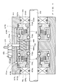
- Fig. 1 is a sectional view showing the general structure of a braking apparatus in accordance with a preferred embodiment of the invention.
- This braking apparatus is composed of a full pneumatic brake mechanism that is substantially similar to that employed in the prior art braking apparatus shown in Fig. 4. Namely, in the braking apparatus of the embodiment, compressed air is allowed to act within the apparatus in response to the ON/OFF control of an electromagnetic valve 65, so as to control the activation/deactivation of the braking function.
- General description on the braking apparatus will be given below with reference to Fig. 1, in which elements similar to those in Fig. 4 are denoted by the same reference characters as in Fig. 4 and will not be described in detail to avoid unnecessary duplication.
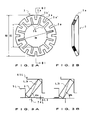
- Figs. 2A and 2B show a specific configuration of coned disk spring 3 forming coned spring sections 3L, 3R of Fig. 1.
- the braking apparatus of Fig. 1 is different from the prior art braking apparatus of Fig. 4 in that each of coned disk spring sections 3L, 3R comprises five coned disk springs and that each of the coned disk springs 3 has a rectangular sectional shape.
- each of the coned disk spring 3 is formed in such a manner that the maximum radial distance Dm between each opposed pair of inner radial recesses 3b is greater than the corresponding distance DM of the prior coned disk spring 73, as shown in Fig. 2A.
- Dm maximum radial distance between each opposed pair of inner radial recesses 3b is greater than the corresponding distance DM of the prior coned disk spring 73, as shown in Fig. 2A.
- each of the coned disk springs 3 has a plurality of outer radial recesses 3a extending from the outer peripheral edge thereof and spaced apart from each other at equal angular intervals, and also a plurality of inner radial recesses 3b extending from the inner peripheral edge thereof and spaced apart from each other at equal angular intervals.
- the outer and inner radial recesses 3a, 3b are arranged in an alternating fashion along the circumference of the coned disk spring 3.
- the inner radial recess 3b has a radial length longer than that of the outer radial recess 3a, i.e., its radial outward end 3b' is located far beyond the radial inward end 3a' of each adjacent outer radial recess 3a.
- This arrangement of the coned disk spring 3 makes it possible to reduce the axial spring constant without the need for changing the wall thickness of the spring 3 itself, and therefore this embodiment can employ at least three or more, namely five coned disk springs 3 provided around the outer peripheral surface of the brake bush 74L or 74R. By thus increasing the number of the coned disk springs 3 employed, each of the springs will have less abrasion and, as a whole, durability of the braking apparatus can be highly enhanced.
- each of the coned disk springs 3 employed in the embodiment also has a substantially rectangular sectional shape as viewed along line B1 - B2.
- the diagonal line L3 of the coned disk spring in the braking state forms angle ⁇ a with respect to the brake bush, which is the same angle as obtained in the prior art braking apparatus (See Fig. 7A).
- the outer and inner peripheral edges of the spring are gradually abraded in such a manner that the initial rectangular sectional shape gradually turns to a parallelogrammatic shape corresponding to the shape of the prior coned disk spring 73 shown in Fig. 7, with the diagonal line L3 in the rectangular sectional shape of the spring 3 being substantially reduced in length or shortened.
- the coned disk spring 3 exhibits the parallelogrammatic sectional shape for the first time only after the braking action has been performed millions of times, and therefore that the spring can perform its braking action another millions of times.
- a cylindrical hole defined in each of the brake pistons 69L, 69R for receiving the corresponding springs 3 has an increased axial length as compared to that of the prior art braking apparatus, and the portion of each of the brake bushes 74L, 74R which contacts the inner peripheral edge of the corresponding coned disk springs also has an increased axial length.
- the brake bushes 74L, 74R are held directly by the cylindrical casing 61 in the prior art braking apparatus, in the present embodiment, the brake bushes 74L, 74R are held by the casing 61 via the spacer members 5L, 5R.
- the spacer members 5L, 5R are displaceable in the radial direction because they are in contact with the casing 61 via unillustrated rubber packing members. Namely, because the brake bushes 74L, 74R in the prior art braking apparatus are caused to move with the axial movement of the casing 61, they would be excessively abraded as by contacting the rod 22 even when the braking apparatus is in the non-braking state, due to deviation from circularity and misalignment resultant from machining errors.
- the brake bushes 74L, 74R are held via the spacer members 5L, 5R so as to displace in the radial direction as the casing 61 moves in the axial direction, the bushes 74L, 74R will not contact the rod 22 and hence excessive abrasion of the bushes can effectively be avoided. This can also greatly enhance durability of the braking apparatus.
- the embodiment is characterized by the features of the coned disk springs that the spring constant of each coned disk spring 3 is reduced as compared to the prior coned disk spring 73 and hence the number of the coned disk springs is increased, and each coned disk spring 3 is formed in a rectangular sectional shape.
- durability of the braking apparatus can also be enhanced by employing only one of the features.
- each coned disk spring 3 has been described as having a rectangular sectional shape, the spring may be formed to be rectangular only in the inner peripheral portion, because, in most cases, it is only the inner peripheral edge that is actually abraded during the braking action.
- the reason why the inner peripheral edge of the coned disk spring 3 is abraded more than the outer peripheral edge is that the outer peripheral edge has a circumference about twice as long as that of the inner peripheral edge.
- each coned disk spring 3 may be greater in wall thickness than the outer peripheral edge and may alternatively have a trapezoidal sectional shape.
- the outer peripheral edge of each coned disk spring 3 can be smaller in wall thickness so as to provided a reduced spring constant, and hence it is allowed to increase the number of the springs employed.
- the inner peripheral edge of each coned disk spring 3 has a greater wall thickness, durability against abrasion can be enhanced.
- abrasion of each coned disk spring can be minimized and durability of the braking apparatus can be greatly enhanced.
- a sufficient braking force can be provided by the apparatus even when the outer and inner peripheral edges of coned disk springs have been abraded to a considerable degree.
Landscapes
- Engineering & Computer Science (AREA)
- General Engineering & Computer Science (AREA)
- Mechanical Engineering (AREA)
- Physics & Mathematics (AREA)
- Fluid Mechanics (AREA)
- Braking Arrangements (AREA)
Description
Claims (4)
- A braking apparatus comprising:characterized in thata substantially columnar rod (22);a brake bush (74L,74R) having a cylindrical shape and provided around said rod (22), said brake bush (74L,74R) being capable of moving relative to said rod (22) axially along an outer surface of said rod (22) and also causing a frictional braking force between said brake bush (74L,74R) and said rod (22) by being pressed radially inwardly against said rod (22);coned disk springs (3L,3R,3) each being bottomlessdish shaped and also having outer and inner radial recesses (3a,3b) extending radially from outer and inner peripheral edges thereof, respectively, said outer and inner recesses (3a,3b) being arranged in an alternating fashion along a circumference of said spring, said coned disk springs (3L,3R,3) being provided in such a manner that the inner peripheral edge of each of said springs contacts an outer peripheral surface of said brake bush (74L,74R);a brake piston (69L,69R) having an inner surface defining a cylindrical hole for providing therein said coned disk springs (3L,3R,3) in such a manner that the outer peripheral edge of each of said springs contacts the inner peripheral surface of said brake piston (69L,69R), said brake piston being capable of moving relative to said rod (22) axially along the outer surface of the rod (22) to axially press said coned disk springs (3L,3R,3) so that each of said springs is axially deformed into a flatter disk shape with the inner peripheral edge thereof compressed radially inwardly, to thereby press said brake bush (74L,74R) radially inwardly against said rod (22); anda cylinder block (61) capable of moving relative to said rod (22) axially along the outer surface of the rod (22) with said coned disk springs (3L,3R,3) and brake piston (69L,69R) held by said cylinder block (61) and also allowing compressed air supplied from outside to act on said brake piston (69L,69R) so that said brake piston is allowed to move axially along an inner surface of said cylinder block (61);said braking apparatus further comprises a holding member (5L,5R) for holding said brake bush (74L,74R) is displaceable in a radial direction toward and away from said rod (22) within said cylinder block (61) and that each of said inner radial recesses (3b) in each of said springs (3L,3R,3) has an increased radial length relative to a radial length of each of said outer radial recesses (3a) in each of said springs (3L,3R,3) so as to achieve a reduced axial spring constant without changing a wall thickness of said spring (3L,3R,3), and that at least three or more of said coned disk springs (3L,3R,3) are provided around said brake bush (74L,74R) so as to obtain a predetermined total spring constant.
- A braking apparatus as defined in claim 1 wherein each of said coned disk springs (3L,3R,3) has a rectangular sectional shape.
- A braking apparatus as defined in claim 1 or 2 wherein each of said inner radial recesses (3b) has a radial length such that a radial outward end thereof is located far beyond a radial inward end of each adjacent one of said outer radial recesses (3a).
- A braking apparatus as defined in one of the claims 1 to 3 wherein said holding members (5L,5R) are supported in such a manner to be displacable in the radial direction with respect to the cylinder block casing (61) via rubber packing members.
Applications Claiming Priority (2)
| Application Number | Priority Date | Filing Date | Title |
|---|---|---|---|
| JP01788993A JP3151737B2 (en) | 1993-01-11 | 1993-01-11 | Brake equipment |
| JP17889/93 | 1993-01-11 |
Publications (2)
| Publication Number | Publication Date |
|---|---|
| EP0606864A1 EP0606864A1 (en) | 1994-07-20 |
| EP0606864B1 true EP0606864B1 (en) | 1998-07-22 |
Family
ID=11956285
Family Applications (1)
| Application Number | Title | Priority Date | Filing Date |
|---|---|---|---|
| EP94100224A Expired - Lifetime EP0606864B1 (en) | 1993-01-11 | 1994-01-08 | Braking apparatus operated via resilient deformation of coned disk springs |
Country Status (4)
| Country | Link |
|---|---|
| US (1) | US5568844A (en) |
| EP (1) | EP0606864B1 (en) |
| JP (1) | JP3151737B2 (en) |
| DE (1) | DE69411760T2 (en) |
Families Citing this family (11)
| Publication number | Priority date | Publication date | Assignee | Title |
|---|---|---|---|---|
| JPH1155602A (en) | 1997-07-31 | 1999-02-26 | Komatsu Ltd | Digital phase matching device |
| DE19821343A1 (en) * | 1998-05-13 | 1999-12-02 | Estebanez Eva Garcia | Pneumatic brake cylinder with piston and piston rod |
| DE10250821A1 (en) * | 2002-10-31 | 2004-05-13 | Knorr-Bremse Systeme für Schienenfahrzeuge GmbH | Braking device with a pressure-operated actuator |
| AT506961B1 (en) * | 2008-09-09 | 2010-01-15 | Miba Sinter Austria Gmbh | GEAR ARRANGEMENT |
| DE102008050471A1 (en) * | 2008-10-04 | 2010-04-08 | Thyssenkrupp Presta Teccenter Ag | Divided gear |
| JP5122500B2 (en) * | 2009-01-30 | 2013-01-16 | カヤバ工業株式会社 | Seal member |
| FR2944077B1 (en) * | 2009-04-06 | 2011-05-06 | Messier Dowty Sa | SLIDING DEVICE WITH CONTROLLED FRICTION, SUCH AS A DAMPER, OPERATING IN BOTH SENSES |
| US8535007B2 (en) * | 2010-05-18 | 2013-09-17 | Hamilton Sundstrand Corporation | Hydraulic actuator locking device |
| CN201909093U (en) * | 2010-12-22 | 2011-07-27 | 济南高仕机械制造有限公司 | Compressed air single-action actuator |
| RU2459125C1 (en) * | 2011-05-05 | 2012-08-20 | Лев Николаевич Бурков | Threaded joint |
| DE112014006659T5 (en) * | 2014-05-13 | 2017-01-26 | Mitsubishi Electric Corporation | Brake device for lift hitch |
Family Cites Families (10)
| Publication number | Priority date | Publication date | Assignee | Title |
|---|---|---|---|---|
| DE1005324B (en) * | 1943-04-27 | 1957-03-28 | Ringspann Maurer Kg A | Radial clamping element |
| FR1207766A (en) * | 1957-07-10 | 1960-02-18 | Dunlop Sa | Adjustment device by infinitely small increments and brake fitted with such a device |
| US2988058A (en) * | 1959-01-10 | 1961-06-13 | Westinghouse Bremsen Gmbh | Locking means for fluid pressure actuated device |
| US3176590A (en) * | 1961-09-01 | 1965-04-06 | Cincinnati Milling Machine Co | Clamping device |
| US3828893A (en) * | 1972-11-22 | 1974-08-13 | Ncr | Servo-drive positioning device |
| DE2845266C2 (en) * | 1978-10-18 | 1983-03-03 | Ringspann Albrecht Maurer Kg, 6380 Bad Homburg | Safety parking brake for hydraulic lifts, lifting platforms and the like. |
| US4480490A (en) * | 1981-10-22 | 1984-11-06 | Inoue-Japax Research Incorporated | Mechanical member |
| US4564088A (en) * | 1984-01-09 | 1986-01-14 | Kyoho Machine Works, Ltd. | Axial braking device |
| DE3506491C2 (en) * | 1985-02-23 | 1993-11-04 | Festo Kg | PRESSURE-OPERATED WORK CYLINDER |
| JPS6438354A (en) * | 1987-08-04 | 1989-02-08 | Ricoh Kk | Automatic separating/discharging device for paper |
-
1993
- 1993-01-11 JP JP01788993A patent/JP3151737B2/en not_active Expired - Lifetime
-
1994
- 1994-01-08 DE DE69411760T patent/DE69411760T2/en not_active Expired - Fee Related
- 1994-01-08 EP EP94100224A patent/EP0606864B1/en not_active Expired - Lifetime
- 1994-01-10 US US08/179,269 patent/US5568844A/en not_active Expired - Lifetime
Also Published As
| Publication number | Publication date |
|---|---|
| JPH06207630A (en) | 1994-07-26 |
| JP3151737B2 (en) | 2001-04-03 |
| EP0606864A1 (en) | 1994-07-20 |
| DE69411760D1 (en) | 1998-08-27 |
| DE69411760T2 (en) | 1999-03-25 |
| US5568844A (en) | 1996-10-29 |
Similar Documents
| Publication | Publication Date | Title |
|---|---|---|
| US5568844A (en) | Braking apparatus operated via resilient deformation of coned disk springs | |
| US4214795A (en) | Piston braking device for hydraulic or pneumatic cylinders | |
| US5460201A (en) | Electromechanical servovalve | |
| JPH0314925A (en) | Drum brake assembling body and manufacture thereof | |
| KR102599465B1 (en) | Braking force simulator for automobiles | |
| CN1312893A (en) | Multiple disc brake system | |
| US5269499A (en) | Snap spring positioning device | |
| US6230851B1 (en) | Air disc brake | |
| KR100471911B1 (en) | Multiple disc brake system | |
| GB2199909A (en) | Disk brake assemblies | |
| US5816371A (en) | Pressure release parking brake actuator | |
| EP4015323A2 (en) | Spring brake actuator for use in a commercial vehicle and commercial vehicle comprising the same | |
| US4860858A (en) | Spot-type disc brake with resetting means | |
| JP4354560B2 (en) | Force transmission assembly | |
| US5542504A (en) | External concentric aircraft brake piston adjuster | |
| US4311220A (en) | Safety catch for elevators, lifting platforms, and the like | |
| CN201326670Y (en) | Clutch-detent assembly | |
| CN112112912B (en) | Spring brake actuator and brake release mechanism for such a spring brake actuator | |
| US11866017B2 (en) | Brake actuator | |
| JP2009115215A (en) | Caliper brake device for vehicle | |
| US6598513B2 (en) | Cylinder apparatus | |
| US5611367A (en) | In-line valve for a master cylinder | |
| JPH0138354Y2 (en) | ||
| KR100428148B1 (en) | An automotive drum brake having multi frictional face | |
| JPH0428291Y2 (en) |
Legal Events
| Date | Code | Title | Description |
|---|---|---|---|
| PUAI | Public reference made under article 153(3) epc to a published international application that has entered the european phase |
Free format text: ORIGINAL CODE: 0009012 |
|
| AK | Designated contracting states |
Kind code of ref document: A1 Designated state(s): DE FR GB |
|
| 17P | Request for examination filed |
Effective date: 19941119 |
|
| 17Q | First examination report despatched |
Effective date: 19961122 |
|
| GRAG | Despatch of communication of intention to grant |
Free format text: ORIGINAL CODE: EPIDOS AGRA |
|
| GRAG | Despatch of communication of intention to grant |
Free format text: ORIGINAL CODE: EPIDOS AGRA |
|
| GRAH | Despatch of communication of intention to grant a patent |
Free format text: ORIGINAL CODE: EPIDOS IGRA |
|
| GRAH | Despatch of communication of intention to grant a patent |
Free format text: ORIGINAL CODE: EPIDOS IGRA |
|
| GRAA | (expected) grant |
Free format text: ORIGINAL CODE: 0009210 |
|
| AK | Designated contracting states |
Kind code of ref document: B1 Designated state(s): DE FR GB |
|
| PG25 | Lapsed in a contracting state [announced via postgrant information from national office to epo] |
Ref country code: FR Free format text: LAPSE BECAUSE OF FAILURE TO SUBMIT A TRANSLATION OF THE DESCRIPTION OR TO PAY THE FEE WITHIN THE PRESCRIBED TIME-LIMIT Effective date: 19980722 |
|
| REF | Corresponds to: |
Ref document number: 69411760 Country of ref document: DE Date of ref document: 19980827 |
|
| EN | Fr: translation not filed | ||
| PLBE | No opposition filed within time limit |
Free format text: ORIGINAL CODE: 0009261 |
|
| STAA | Information on the status of an ep patent application or granted ep patent |
Free format text: STATUS: NO OPPOSITION FILED WITHIN TIME LIMIT |
|
| 26N | No opposition filed | ||
| PGFP | Annual fee paid to national office [announced via postgrant information from national office to epo] |
Ref country code: GB Payment date: 20001227 Year of fee payment: 8 |
|
| PGFP | Annual fee paid to national office [announced via postgrant information from national office to epo] |
Ref country code: DE Payment date: 20001228 Year of fee payment: 8 |
|
| REG | Reference to a national code |
Ref country code: GB Ref legal event code: IF02 |
|
| PG25 | Lapsed in a contracting state [announced via postgrant information from national office to epo] |
Ref country code: GB Free format text: LAPSE BECAUSE OF NON-PAYMENT OF DUE FEES Effective date: 20020108 |
|
| PG25 | Lapsed in a contracting state [announced via postgrant information from national office to epo] |
Ref country code: DE Free format text: LAPSE BECAUSE OF NON-PAYMENT OF DUE FEES Effective date: 20020801 |
|
| GBPC | Gb: european patent ceased through non-payment of renewal fee |
Effective date: 20020108 |