EP0606782B1 - Heizanlage für Räume - Google Patents
Heizanlage für Räume Download PDFInfo
- Publication number
- EP0606782B1 EP0606782B1 EP93310648A EP93310648A EP0606782B1 EP 0606782 B1 EP0606782 B1 EP 0606782B1 EP 93310648 A EP93310648 A EP 93310648A EP 93310648 A EP93310648 A EP 93310648A EP 0606782 B1 EP0606782 B1 EP 0606782B1
- Authority
- EP
- European Patent Office
- Prior art keywords
- head
- duct
- burner
- appliance
- flow
- Prior art date
- Legal status (The legal status is an assumption and is not a legal conclusion. Google has not performed a legal analysis and makes no representation as to the accuracy of the status listed.)
- Expired - Lifetime
Links
- 238000010438 heat treatment Methods 0.000 title claims abstract description 15
- 239000000446 fuel Substances 0.000 claims abstract description 13
- 230000000712 assembly Effects 0.000 claims abstract description 9
- 238000000429 assembly Methods 0.000 claims abstract description 9
- 239000007789 gas Substances 0.000 claims description 15
- 239000000203 mixture Substances 0.000 claims description 15
- 230000005855 radiation Effects 0.000 claims description 7
- 238000002485 combustion reaction Methods 0.000 claims description 6
- 239000011159 matrix material Substances 0.000 claims description 4
- 238000011144 upstream manufacturing Methods 0.000 claims description 3
- 230000001154 acute effect Effects 0.000 claims description 2
- 230000001939 inductive effect Effects 0.000 claims description 2
- 239000002184 metal Substances 0.000 claims description 2
- 239000012141 concentrate Substances 0.000 claims 2
- 238000009499 grossing Methods 0.000 claims 1
- 238000009434 installation Methods 0.000 description 6
- 230000000694 effects Effects 0.000 description 2
- 239000000919 ceramic Substances 0.000 description 1
- 238000010276 construction Methods 0.000 description 1
- 230000001419 dependent effect Effects 0.000 description 1
- 239000012530 fluid Substances 0.000 description 1
- 230000000977 initiatory effect Effects 0.000 description 1
- 238000009413 insulation Methods 0.000 description 1
- 230000014759 maintenance of location Effects 0.000 description 1
- 230000002093 peripheral effect Effects 0.000 description 1
- 230000001681 protective effect Effects 0.000 description 1
- 230000001105 regulatory effect Effects 0.000 description 1
- 238000007493 shaping process Methods 0.000 description 1
- 229910001220 stainless steel Inorganic materials 0.000 description 1
- 239000010935 stainless steel Substances 0.000 description 1
- 230000002459 sustained effect Effects 0.000 description 1
Images


Classifications
-
- F—MECHANICAL ENGINEERING; LIGHTING; HEATING; WEAPONS; BLASTING
- F23—COMBUSTION APPARATUS; COMBUSTION PROCESSES
- F23D—BURNERS
- F23D14/00—Burners for combustion of a gas, e.g. of a gas stored under pressure as a liquid
- F23D14/46—Details, e.g. noise reduction means
- F23D14/48—Nozzles
- F23D14/58—Nozzles characterised by the shape or arrangement of the outlet or outlets from the nozzle, e.g. of annular configuration
- F23D14/583—Nozzles characterised by the shape or arrangement of the outlet or outlets from the nozzle, e.g. of annular configuration of elongated shape, e.g. slits
- F23D14/586—Nozzles characterised by the shape or arrangement of the outlet or outlets from the nozzle, e.g. of annular configuration of elongated shape, e.g. slits formed by a set of sheets, strips, ribbons or the like
-
- F—MECHANICAL ENGINEERING; LIGHTING; HEATING; WEAPONS; BLASTING
- F23—COMBUSTION APPARATUS; COMBUSTION PROCESSES
- F23C—METHODS OR APPARATUS FOR COMBUSTION USING FLUID FUEL OR SOLID FUEL SUSPENDED IN A CARRIER GAS OR AIR
- F23C3/00—Combustion apparatus characterised by the shape of the combustion chamber
- F23C3/002—Combustion apparatus characterised by the shape of the combustion chamber the chamber having an elongated tubular form, e.g. for a radiant tube
-
- F—MECHANICAL ENGINEERING; LIGHTING; HEATING; WEAPONS; BLASTING
- F23—COMBUSTION APPARATUS; COMBUSTION PROCESSES
- F23D—BURNERS
- F23D14/00—Burners for combustion of a gas, e.g. of a gas stored under pressure as a liquid
- F23D14/46—Details, e.g. noise reduction means
- F23D14/62—Mixing devices; Mixing tubes
-
- F—MECHANICAL ENGINEERING; LIGHTING; HEATING; WEAPONS; BLASTING
- F24—HEATING; RANGES; VENTILATING
- F24D—DOMESTIC- OR SPACE-HEATING SYSTEMS, e.g. CENTRAL HEATING SYSTEMS; DOMESTIC HOT-WATER SUPPLY SYSTEMS; ELEMENTS OR COMPONENTS THEREFOR
- F24D5/00—Hot-air central heating systems; Exhaust gas central heating systems
- F24D5/06—Hot-air central heating systems; Exhaust gas central heating systems operating without discharge of hot air into the space or area to be heated
- F24D5/08—Hot-air central heating systems; Exhaust gas central heating systems operating without discharge of hot air into the space or area to be heated with hot air led through radiators
Definitions
- This invention relates to radiant tube space heating appliances of the kind comprising a radiation tube or duct, commonly suspended overhead in the space to be heated, a fan or other pump for inducing flow of gases along the duct in use. and one or more fluid fuelled burner assemblies, typically gas fired and automatically controlled, for feeding hot gases into said flow. Radiant heat is emitted from the duct surface and this is commonly directed and concentrated, e.g. in a downward direction, by reflectors mounted adjacent to the duct. Said appliances are hereinafter referred to as "radiant tube heating appliances”.
- the object of the invention is to provide a radiant tube heating appliance which is reliable and efficient in operation, and which gives improved performance and output.
- the arrangement of the invention has the effect of concentrating the flow of mix issuing from the mouth in use towards the distal end of the slot remote from the mixing unit so that more combustion takes place adjacent to a circumferential zone of the duct wall at the side opposite to said mixing unit to increase radiant heat output from that zone which will be operatively mounted to face e.g. downwardly or otherwise towards the parts of the space where most heat is required.
- said burner mouth will include a honeycomb or other matrix, e.g. formed from corrugated or other strip stainless steel or other metal, to prevent burning back into the head and smooth and further direct the outflow of mix therefrom.
- a honeycomb or other matrix e.g. formed from corrugated or other strip stainless steel or other metal
- the mixing unit includes connections for feeding gas fuel and combustion air to the fuel mix passage of the head which are positioned at or towards the rear and upstream facing wall thereof so that the inflows into the head for mixing therein are further concentrated in the direction of said distal end of the slot.
- the proportions of the slot forming the burner mouth will have a major dimension: minor dimension ratio of at least 2.8:1.
- the heating appliance may include a plurality of said burner assemblies spaced at intervals along a common radiation duct.
- Said assemblies may be disposed in series along a single duct length or may act in parallel in limbs of a branched duct and they may all be controlled in common or may have a degree of independent control dependent on requirements for the particular installation.
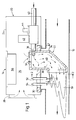
- the radiant tube space heating appliance of this example is an installation for heating a large space such as a factory building or public hall; the overall installation is generally conventional comprising branched runs of radiation duct being circular section tube 10 mounted overhead, e.g. near roof or ceiling level and provided with reflectors 12 for directing and concentrating the emitted radiant heat downwards in known manner.
- Hot gases provided by burner assemblies 14 at spaced intervals along each branch are drawn through the tube 10 by a common exhaust fan 16 leading to a discharge flue 18.
- Fan 16 is automatically controlled in known manner to maintain negative pressure in the system of tube 10 i.e. a degree of depression below the ambient atmosphere pressure and the gas flow in the various branches may be further regulated and balanced by manual or automatic dampers (not shown) in known manner.
- burner assemblies 14 will now be described in greater detail with reference to Figures 1-3. It comprises a fuel/air infeed and control unit 20 mounted externally on the upper periphery of tube 10 and a burner head 22 which projects downwardly into the tube as described in greater detail below.
- Unit 20 includes a box 24 defining an air chamber 26 which also serves as a protective enclosure for components of the unit, air being drawn into box 24 through a baffled air inlet 28 at one end.
- An air filter may also be provided.
- burner head 22 projects through a mounting plate 30 forming part of the floor of box 24 and which is secured to a flanged opening in the top of tube 10.
- the top of head 22 defines an air infeed opening 32 communicating directly with chamber 26 and which is off-centre, being positioned nearer to the rear wall 34 of head 22 than to its front wall 36 so that the air inflow is concentrated towards said rear wall.
- a gas fuel nozzle 38 also opens into the upper part of head 22 through the top of rear wall 34 and is connected to a gas fuel feed pipe 40 through a safety cut-off valve 42 and a gas pressure governor 44.
- the hollow interior of burner head 22 constitutes a fuel mix passage 46, the air and gas fuel inputs being proportioned so that a combustible mix is produced.
- the lower part of head 22 within tube 10 projects into the path of flow of gases induced along tube 10 from right to left as viewed in Figure 1 and the lower part of front wall 36 defines a rectangular burner mouth 48 on a diametral plane of tube 10 and angled to face downstream of the path of flow along tube 10.
- Mouth 48 is in the form of an elongated slot as best seen in the elevation of Figure 2, its height, i.e. extent lengthwise of front wall 36 being considerably greater than its width. Mouth 48 is centered in tube 10, and in this example its height is around two thirds of the tube diameter. The ratio of height to width of the mouth is preferably at least 2.8:1.
- the overall width of head 22 is only slightly greater than the width of mouth 48 but the depth between the front wall 36 and rear wall 34 is substantially greater.
- To provide streamlining rear wall 34 has only a short vertical section depending from plate 30 and is then angled to slope downwards at about 45 degrees towards the bottom of mouth 48.
- Said rear wall is also V shaped in horizontal section as shown in Figure 3 so that its exterior faces form an acute angle pointing upstream of the throughflow.
- Plate 30 also mounts a conventional electrical ignition device 52 for initiating combustion of the mix on start-up and a conventional flame sensing electrode 54 acting in conjunction with cut-off valve 42 to terminate the gas fuel supply in case of flame failure, these controls being associated with an electrical module 56 of the burner assembly in known manner.
- the burner head will operate at a negative pressure of at least 2 mba within its mix passage 46 and all the air required for combustion of the gas fuel is pre-mixed in said passage prior to discharge from mouth 48.
- the use of the honeycomb matrix 50 in the mouth also provides improvements in efficiency and performance in comparison with the multi-port ceramic burner mouth inserts used in some known appliances.
Landscapes
- Engineering & Computer Science (AREA)
- Chemical & Material Sciences (AREA)
- Combustion & Propulsion (AREA)
- Mechanical Engineering (AREA)
- General Engineering & Computer Science (AREA)
- Physics & Mathematics (AREA)
- Thermal Sciences (AREA)
- Gas Burners (AREA)
- Sorption Type Refrigeration Machines (AREA)
- Crystals, And After-Treatments Of Crystals (AREA)
- Baking, Grill, Roasting (AREA)
- Cookers (AREA)
Claims (9)
- Strahlungsröhren-Heizanlage, enthaltend eine Strahlungsleitung (10), einen Ventilator bzw. eine andere Pumpvorrichtung (16) zur Erzeugung einer Gasströmung durch die Leitung sowie wenigstens eine Brenneranordnung (14), die einen sich von einer Kontroll- und Brennstoffmischeinheit (20) der Anordnung seitlich ins Innere der Strahlungsröhre (10) in den durch diese Röhre verlaufenden Strömungsweg hinein erstreckenden Brennerkopf (22) enthält, der einen Brennstoffmischdurchlaß (46) begrenzt, welcher zu einer Brennerdüse (48) führt, die von einer Vorderwand (36) des Brennerkopfes begrenzt wird, welche in einem solchen Winkel angeordnet ist, daß sie stromabwärts zum Strömungsweg ausgerichtet ist, so daß das Gemisch im Betriebszustand zur Verbrennung in der Leitung direkt unterhalb des Brennerkopfes in Strömungsrichtung eingeblasen wird, dadurch gekennzeichnet, daß die Brennerdüse als einzelner länglicher Schlitz ausgebildet ist, über dessen gesamte Fläche hinweg im Betriebszustand keine nennenswerten Hindernisse für das Ausfließen des Gemisches durch die Düse vorhanden sind, wobei die Düse längs zum Brennerkopf in der Richtung, in der sie sich in die Leitung hinein erstreckt, eine große Abmessung und quer zum Brennerkopf in einer senkrecht zur Achse des Strömungswegs verlaufenden Ebene eine kleine Abmessung aufweist, sowie dadurch, daß die Gesamtbreite des Brennerkopfes in der Leitung ein wenig größer ist als die kleine Abmessung des Schlitzes, so daß das Einströmen durch den Brennerkopf in die Leitung nur minimal behindert wird.
- Anlage nach Anspruch 1, dadurch gekennzeichnet, daß die Brennerdüse (48) innerhalb des Schlitzes eine zellenartige oder anders gestaltete Gewebeschicht (50) aufweist, die aus gewelltem oder anderes geformten Metallstreifen besteht, welche seitlich zur Ausströmrichtung durch den Schlitz angeordnet sind, um eine Rückfeuerung in den Brennerkopf hinein zu verhindern und ein reibungsloses, gerichtetes Ausfließen des Gemisches aus dem Brennerkopf sicherzustellen.
- Anlage nach Anspruch 2, dadurch gekennzeichnet, daß die Leitung einen kreisförmigen Querschnitt aufweist und die größere Abmessung des Schlitzes etwa zwei Drittel des Leitungsdurchmessers abdeckt.
- Anlage nach Anspruch 1, 2 oder 3, dadurch gekennzeichnet, daß beim Schlitz das Verhältnis der größeren zur kleineren Abmessung wenigstens 2,8 : 1 beträgt.
- Anlage nach einem der vorangegangenen Ansprüche, dadurch gekennzeichnet, daß ein beträchtlicher Teil der Rückwand (34) des Brennerkopfes (22) in einem solchen Winkel ausgerichtet ist, daß dieser Teil an seinem der Einheit (20) fernen Ende zur Kante der Brennerdüse (48) hin konvergiert.
- Anlage nach einem der vorangegangenen Ansprüche, wobei die Rückwand (34) des Brennerkopfes (22) einen V-förmigen Querschnitt aufweist, wodurch ihre Außenseiten einen spitzen Winkel bilden, dessen Spitze stromaufwärts zum Strömungsweg ausgerichtet ist.
- Anlage nach einem der vorangegangenen Ansprüche, dadurch gekennzeichnet, daß eine direkt von einer Luftkammer (26) der Einheit kommende Luftzuführöffnung (32) des Brennerkopfes (22) an einer Stelle vorgesehen ist, die sich näher an der Rückwand (34) des Brennerkopfes als an dessen Vorderwand (36) befindet, wodurch die einströmende Luft zur Rückwand hin konzentriert wird.
- Anlage nach einem der vorangegangenen Ansprüche, wobei die Strahlungsleitung bzw. Röhre (10) im Betriebszustand im zu beheizenden Raum aufgehängt bzw. an der Decke angebracht ist, dadurch gekennzeichnet, daß die Brenneranordnung (14) so befestigt ist, daß der Brennerkopf (22) sich von der Einheit (20) derart nach unten erstreckt, daß er zum unteren Teil der Leitungswand hin vorsteht, wodurch im Betriebszustand eine konzentrierte Strahlungswärmeabgabe vom unteren Bereich der Leitung aus erfolgt.
- Heizanlage nach einem der vorangegangenen Ansprüche, dadurch gekennzeichnet, daß im Betriebszustand eine Vielzahl von Brenneranordnungen (14) in bestimmten Abständen zueinander entlang einer gemeinsamen, verzweigten bzw. in anderer Weise gestalteten Strahlungsröhre bzw. Leitung (10) derart angeordnet ist, daß die Brenneranordnungen darin in Reihe und/oder parallel zueinander zum Einsatz kommen.
Applications Claiming Priority (2)
| Application Number | Priority Date | Filing Date | Title |
|---|---|---|---|
| GB9300612A GB2274703B (en) | 1993-01-14 | 1993-01-14 | Space heating appliances |
| GB9300612 | 1993-01-14 |
Publications (2)
| Publication Number | Publication Date |
|---|---|
| EP0606782A1 EP0606782A1 (de) | 1994-07-20 |
| EP0606782B1 true EP0606782B1 (de) | 1999-06-30 |
Family
ID=10728674
Family Applications (1)
| Application Number | Title | Priority Date | Filing Date |
|---|---|---|---|
| EP93310648A Expired - Lifetime EP0606782B1 (de) | 1993-01-14 | 1993-12-31 | Heizanlage für Räume |
Country Status (4)
| Country | Link |
|---|---|
| EP (1) | EP0606782B1 (de) |
| AT (1) | ATE181766T1 (de) |
| DE (1) | DE69325502T2 (de) |
| GB (1) | GB2274703B (de) |
Families Citing this family (6)
| Publication number | Priority date | Publication date | Assignee | Title |
|---|---|---|---|---|
| JP3460441B2 (ja) * | 1996-04-09 | 2003-10-27 | トヨタ自動車株式会社 | 燃焼装置および該燃焼装置を具備した熱設備 |
| US5842854A (en) * | 1996-04-18 | 1998-12-01 | Willms; Eric | Infrared heating system and metering element |
| GB2331146B (en) | 1997-11-06 | 2001-10-17 | Ambi Rad Ltd | Space heating appliances |
| CA2311520C (en) | 1997-11-26 | 2006-05-30 | Roberts-Gordon Llc | Gas fired infrared radiant tube heating system using plural burner assemblies and single gas delivery system |
| DE102006049875A1 (de) * | 2006-10-23 | 2008-04-24 | Robert Bosch Gmbh | Gemischbildungseinrichtung |
| DE102011050143A1 (de) | 2011-05-05 | 2012-11-08 | Waldemar Marinitsch | Kraftsensor |
Family Cites Families (5)
| Publication number | Priority date | Publication date | Assignee | Title |
|---|---|---|---|---|
| GB2070227B (en) * | 1980-02-15 | 1983-07-13 | Roberts Appliance Corp Gordon | Radiant heating system having an improved burner head |
| GB2102555B (en) * | 1981-07-17 | 1985-03-20 | Phoenix Burners | A heating system |
| ES2035057T3 (es) * | 1986-06-04 | 1993-04-16 | Ambi-Rad Limited | Aparato para calentar espacios. |
| NL8900900A (nl) * | 1989-04-11 | 1990-11-01 | Hoaf Ray O Therm B V | Infrarood-verwarmingssysteem. |
| GB2236406B (en) * | 1989-09-12 | 1993-08-18 | Radiant Systems Technology Ltd | Radiant heating systems |
-
1993
- 1993-01-14 GB GB9300612A patent/GB2274703B/en not_active Expired - Fee Related
- 1993-12-31 DE DE69325502T patent/DE69325502T2/de not_active Expired - Fee Related
- 1993-12-31 EP EP93310648A patent/EP0606782B1/de not_active Expired - Lifetime
- 1993-12-31 AT AT93310648T patent/ATE181766T1/de not_active IP Right Cessation
Also Published As
| Publication number | Publication date |
|---|---|
| DE69325502D1 (de) | 1999-08-05 |
| ATE181766T1 (de) | 1999-07-15 |
| DE69325502T2 (de) | 2000-01-20 |
| GB2274703A (en) | 1994-08-03 |
| GB2274703B (en) | 1996-06-26 |
| EP0606782A1 (de) | 1994-07-20 |
| GB9300612D0 (en) | 1993-03-03 |
Similar Documents
| Publication | Publication Date | Title |
|---|---|---|
| US6758208B2 (en) | Flexible gas-fired heat exchanger system | |
| US9080773B2 (en) | Pitot tube pressure sensor for radiant tube heater | |
| US7874835B2 (en) | Radiant tube heater and burner assembly for use therein | |
| CA2002488C (en) | Forced draft direct vent system for a water heater | |
| AU694324B2 (en) | Power-vented, direct-vent water heater | |
| US5628303A (en) | Radiant space heater for residential use | |
| US7913683B2 (en) | Radiant tube heater | |
| EP0606782B1 (de) | Heizanlage für Räume | |
| US20020092516A1 (en) | Flexible gas-fired heat exchanger system | |
| US4103669A (en) | Fireplace heat exchanger assembly | |
| US5293860A (en) | Standing pilot furnace with vented vestibule | |
| US3311155A (en) | Sealed combustion gas furnace | |
| USRE37128E1 (en) | Standing pilot furnace with vented vestibule | |
| CA2331168C (en) | Flexible gas-fired heat exchanger system | |
| US6217320B1 (en) | Space heating appliances | |
| CA1147225A (en) | Combustion device | |
| US4453532A (en) | Water heater for use in fireplace | |
| US2594608A (en) | Fuel-burning panel heater | |
| EP0635675B1 (de) | Raumheizvorrichtungen | |
| US4848315A (en) | Apparatus for supplying heated air to an air system | |
| EP0169689A2 (de) | Infrarotheizungsanlage | |
| CA2311520C (en) | Gas fired infrared radiant tube heating system using plural burner assemblies and single gas delivery system | |
| GB2193305A (en) | Space heating appliance | |
| JP3435468B2 (ja) | 温風暖房機 | |
| GB2114726A (en) | Improvements in or relating to gas-fired space heaters |
Legal Events
| Date | Code | Title | Description |
|---|---|---|---|
| PUAI | Public reference made under article 153(3) epc to a published international application that has entered the european phase |
Free format text: ORIGINAL CODE: 0009012 |
|
| AK | Designated contracting states |
Kind code of ref document: A1 Designated state(s): AT BE CH DE DK ES FR GR IE IT LI LU NL PT SE |
|
| 17P | Request for examination filed |
Effective date: 19941223 |
|
| 17Q | First examination report despatched |
Effective date: 19960916 |
|
| GRAG | Despatch of communication of intention to grant |
Free format text: ORIGINAL CODE: EPIDOS AGRA |
|
| GRAG | Despatch of communication of intention to grant |
Free format text: ORIGINAL CODE: EPIDOS AGRA |
|
| GRAH | Despatch of communication of intention to grant a patent |
Free format text: ORIGINAL CODE: EPIDOS IGRA |
|
| RAP1 | Party data changed (applicant data changed or rights of an application transferred) |
Owner name: AMBI-RAD LIMITED |
|
| GRAH | Despatch of communication of intention to grant a patent |
Free format text: ORIGINAL CODE: EPIDOS IGRA |
|
| GRAA | (expected) grant |
Free format text: ORIGINAL CODE: 0009210 |
|
| AK | Designated contracting states |
Kind code of ref document: B1 Designated state(s): AT BE CH DE DK ES FR GR IE IT LI LU NL PT SE |
|
| PG25 | Lapsed in a contracting state [announced via postgrant information from national office to epo] |
Ref country code: SE Free format text: THE PATENT HAS BEEN ANNULLED BY A DECISION OF A NATIONAL AUTHORITY Effective date: 19990630 Ref country code: NL Free format text: LAPSE BECAUSE OF FAILURE TO SUBMIT A TRANSLATION OF THE DESCRIPTION OR TO PAY THE FEE WITHIN THE PRESCRIBED TIME-LIMIT Effective date: 19990630 Ref country code: LI Free format text: LAPSE BECAUSE OF FAILURE TO SUBMIT A TRANSLATION OF THE DESCRIPTION OR TO PAY THE FEE WITHIN THE PRESCRIBED TIME-LIMIT Effective date: 19990630 Ref country code: IT Free format text: LAPSE BECAUSE OF FAILURE TO SUBMIT A TRANSLATION OF THE DESCRIPTION OR TO PAY THE FEE WITHIN THE PRE;WARNING: LAPSES OF ITALIAN PATENTS WITH EFFECTIVE DATE BEFORE 2007 MAY HAVE OCCURRED AT ANY TIME BEFORE 2007. THE CORRECT EFFECTIVE DATE MAY BE DIFFERENT FROM THE ONE RECORDED.SCRIBED TIME-LIMIT Effective date: 19990630 Ref country code: GR Free format text: LAPSE BECAUSE OF NON-PAYMENT OF DUE FEES Effective date: 19990630 Ref country code: ES Free format text: THE PATENT HAS BEEN ANNULLED BY A DECISION OF A NATIONAL AUTHORITY Effective date: 19990630 Ref country code: CH Free format text: LAPSE BECAUSE OF FAILURE TO SUBMIT A TRANSLATION OF THE DESCRIPTION OR TO PAY THE FEE WITHIN THE PRESCRIBED TIME-LIMIT Effective date: 19990630 Ref country code: BE Free format text: LAPSE BECAUSE OF FAILURE TO SUBMIT A TRANSLATION OF THE DESCRIPTION OR TO PAY THE FEE WITHIN THE PRESCRIBED TIME-LIMIT Effective date: 19990630 Ref country code: AT Free format text: LAPSE BECAUSE OF FAILURE TO SUBMIT A TRANSLATION OF THE DESCRIPTION OR TO PAY THE FEE WITHIN THE PRESCRIBED TIME-LIMIT Effective date: 19990630 |
|
| REF | Corresponds to: |
Ref document number: 181766 Country of ref document: AT Date of ref document: 19990715 Kind code of ref document: T |
|
| REG | Reference to a national code |
Ref country code: CH Ref legal event code: EP |
|
| REF | Corresponds to: |
Ref document number: 69325502 Country of ref document: DE Date of ref document: 19990805 |
|
| REG | Reference to a national code |
Ref country code: IE Ref legal event code: FG4D |
|
| PG25 | Lapsed in a contracting state [announced via postgrant information from national office to epo] |
Ref country code: PT Free format text: LAPSE BECAUSE OF FAILURE TO SUBMIT A TRANSLATION OF THE DESCRIPTION OR TO PAY THE FEE WITHIN THE PRESCRIBED TIME-LIMIT Effective date: 19990930 Ref country code: DK Free format text: LAPSE BECAUSE OF FAILURE TO SUBMIT A TRANSLATION OF THE DESCRIPTION OR TO PAY THE FEE WITHIN THE PRESCRIBED TIME-LIMIT Effective date: 19990930 |
|
| ET | Fr: translation filed | ||
| NLV1 | Nl: lapsed or annulled due to failure to fulfill the requirements of art. 29p and 29m of the patents act | ||
| PG25 | Lapsed in a contracting state [announced via postgrant information from national office to epo] |
Ref country code: LU Free format text: LAPSE BECAUSE OF NON-PAYMENT OF DUE FEES Effective date: 19991231 Ref country code: IE Free format text: LAPSE BECAUSE OF NON-PAYMENT OF DUE FEES Effective date: 19991231 |
|
| REG | Reference to a national code |
Ref country code: CH Ref legal event code: PL |
|
| PLBE | No opposition filed within time limit |
Free format text: ORIGINAL CODE: 0009261 |
|
| STAA | Information on the status of an ep patent application or granted ep patent |
Free format text: STATUS: NO OPPOSITION FILED WITHIN TIME LIMIT |
|
| 26N | No opposition filed | ||
| REG | Reference to a national code |
Ref country code: IE Ref legal event code: MM4A |
|
| PGFP | Annual fee paid to national office [announced via postgrant information from national office to epo] |
Ref country code: DE Payment date: 20051215 Year of fee payment: 13 |
|
| PGFP | Annual fee paid to national office [announced via postgrant information from national office to epo] |
Ref country code: FR Payment date: 20051230 Year of fee payment: 13 |
|
| PG25 | Lapsed in a contracting state [announced via postgrant information from national office to epo] |
Ref country code: DE Free format text: LAPSE BECAUSE OF NON-PAYMENT OF DUE FEES Effective date: 20070703 |
|
| REG | Reference to a national code |
Ref country code: FR Ref legal event code: ST Effective date: 20070831 |
|
| PG25 | Lapsed in a contracting state [announced via postgrant information from national office to epo] |
Ref country code: FR Free format text: LAPSE BECAUSE OF NON-PAYMENT OF DUE FEES Effective date: 20070102 |