EP0606708B1 - Selbst-führende Rolle zum Rillen eines formbaren Rohres - Google Patents
Selbst-führende Rolle zum Rillen eines formbaren Rohres Download PDFInfo
- Publication number
- EP0606708B1 EP0606708B1 EP93308107A EP93308107A EP0606708B1 EP 0606708 B1 EP0606708 B1 EP 0606708B1 EP 93308107 A EP93308107 A EP 93308107A EP 93308107 A EP93308107 A EP 93308107A EP 0606708 B1 EP0606708 B1 EP 0606708B1
- Authority
- EP
- European Patent Office
- Prior art keywords
- pipe
- grooving
- roll
- female
- body portion
- Prior art date
- Legal status (The legal status is an assumption and is not a legal conclusion. Google has not performed a legal analysis and makes no representation as to the accuracy of the status listed.)
- Expired - Lifetime
Links
Images


Classifications
-
- B—PERFORMING OPERATIONS; TRANSPORTING
- B21—MECHANICAL METAL-WORKING WITHOUT ESSENTIALLY REMOVING MATERIAL; PUNCHING METAL
- B21D—WORKING OR PROCESSING OF SHEET METAL OR METAL TUBES, RODS OR PROFILES WITHOUT ESSENTIALLY REMOVING MATERIAL; PUNCHING METAL
- B21D17/00—Forming single grooves in sheet metal or tubular or hollow articles
- B21D17/04—Forming single grooves in sheet metal or tubular or hollow articles by rolling
Definitions
- This grooving can be accomplished by a groove rolling machine.
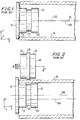
- the radially extending flange is provided to provide an abutment for the end of the pipe at the time it is placed on the female grooving roll, and also, in order to restrain the thin-walled metal pipe from spiraling onto the female grooving roll during a rolling operation.
- the female and male grooving rolls 10 and 14 are respective mounted on arbors, one or both of which are driven by suitable motor means, such as electric motors, or they may be manually driven.
- the male grooving roll is supported for movement towards the female grooving roll in the direction of the arrow A in any convenient manner, for example, as is taught in Thau, Jr., et al U.S. patent No. 3,903,722.
- the female grooving roll 40 configuring the female grooving roll 40 to have a generally conical form, which may be formed by a plurality of cylindrical segments that intersect the surface of a frustum of a cone, indicated by the chain lines 46 in Fig. 4, Fig. 4 being a diagrammatical cross-section taken in the x-z plane, and Fig. 5 being a diagrammatical cross-section taken in the x-y plane.
- the male grooving roll 14 is the same as the grooving roll described with reference to the prior art, the male grooving roll 14, as shown in Fig. 5 being comprised of axially straight truly cylindrical sections 24, 25 and 26, the male grooving roll 14 in the same manner being moved in the direction of the arrow A.
- the female grooving roll which is power-driven, will have the further beneficial effect of forcing the pipe C leftwards in the direction of the arrow C in Fig. 5, this being due to the slight difference in linear velocity between the cylindrical portion 41 and the slightly lower linear velocity of the portions 42, 43 and 44.
- This difference in linear velocities will initially cause a skewing of the pipe in the x-z plane in the event that there is no manual restraint imposed on the pipe, in the same manner as that deliberately imposed in Fig. 1 by skewing at the acute angle 30, the generation of that minor skewing action having the beneficial effect of forcing the pipe leftwards in the direction of the arrow C in a similar manner to that intended in Fig. 1, but with a cumulative effect of causing the pipe 16 to spiral onto the female grooving roll 40.
- the female grooving roll 40 could in fact be formed as a frustum of a cone as indicated by the chain lines 46. This, however, would cause complications in the desired knurling of the surfaces of the cylindrical portions 41 - 44, which is relatively easy to provide on a cylindrical surface, but is difficult to provide on a tapered surface due to the continuous change in diametrical pitch of the taper.
- the female rolling die 40 is shown as a frustum of a stepped cylindrical pyramid, in which the stepped edges of the respective cylindrical portions 41 - 44 each lie on the surface of a straight-sided imaginary cone 46.
- Other configurations are possible, in which the stepped edges of the cylindrical portions 41 - 46 lie on the surface of a frustum of a cone having curvilinear sides.
Landscapes
- Engineering & Computer Science (AREA)
- Mechanical Engineering (AREA)
- Shaping Of Tube Ends By Bending Or Straightening (AREA)
- Reduction Rolling/Reduction Stand/Operation Of Reduction Machine (AREA)
- Processing And Handling Of Plastics And Other Materials For Molding In General (AREA)
- Rolls And Other Rotary Bodies (AREA)
- Extrusion Moulding Of Plastics Or The Like (AREA)
Claims (13)
- Walzrillverfahren, worin eine ringförmige Rille rund um die Wand eines zylindrischen formbaren Metallrohrs (16) benachbart seinem Ende ausgebildet wird, umfassend die folgenden Schritte:(a) Positionieren des Rohrendes (16) über einer drehbaren Rillwalze (40) mit Negativprofil, die einen am Rohr angreifenden Abschnitt aufweist, der innen am Rohr angreift, und einen ersten am Rohr angreifenden Körperabschnitt (41, 42), der zum Rohrende hin positioniert ist, einen zweiten am Rohr angreifenden Körperabschnitt (43, 44), der zum Rohrinneren hin positioniert ist, und eine in Längsrichtung gesehen dazwischenliegende Umfangsrillnut (22) zwischen dem ersten und dem zweiten Körperabschnitt (41, 42; 43, 44) umfasst;(b) Einklemmen der Rohrwand zwischen der Rillwalze (40) mit Negativprofil und einer Rillwalze (14) mit Positivprofil, die außerhalb des Rohrs (16) angeordnet ist und eine Umfangsrillrippe (26) aufweist, die zur Rillnut (22) der Walze (40) mit Negativprofil komplementär ist; und(c) Hindurchdrehen der Rohrwand durch den Klemmbereich der Walzen (14, 40) mit Positiv- und Negativprofil, um die ringförmige Rille um die Rohrwand herum einzudrücken,
gekennzeichnet durchdie Verwendung einer Rillwalze (40) mit Negativprofil, in der der erste am Rohr angreifende Körperabschnitt (41, 42) einen größeren Radius aufweist als der zweite am Rohr angreifende Körperabschnitt (43, 44), um über die Rillausnehmung (22) eine Radiusverringerung zu ergeben, wodurch während des Rillens die Achse (16A) des zylindrischen Rohrs (16) von der Achse (40A) der Rillwalze (40) mit Negativprofil weg geneigt ist, was verursacht, daß das Rohr (16) dazu neigt, sich spiralförmig auf die Rillwalze (40) mit Negativprofil zu bewegen, jedoch durch den Angriff an einem Begrenzungswiderlager (12), das benachbart zum ersten am Rohr angreifenden Körperabschnitt (41, 42) der Rillwalze (40) mit Negativprofil angeordnet ist, an einer solchen Spiralbewegung gehindert wird. - Verfahren nach Anspruch 1, worin die Rillwalze (40) mit Negativprofil eine Vielzahl koaxialer zylindrischer Segmente (42, 43) von sich verringerndem Radius aufweist, um die Radiusverringerung über die Rillnut (22) hinweg zu ermöglichen.
- Verfahren nach Anspruch 2, worin der erste Körperabschnitt (41, 42) mehrere benachbarte, axial gerade, zylindrische Abschnitte besitzt, deren jeweilige Durchmesser zur Rillausnehmung (22) hin abnehmen.
- Verfahren nach Anspruch 2 oder 3, worin der zweite Körperabschnitt (43, 44) mehrere benachbarte, axial gerade, zylindrische Oberflächenabschnitte besitzt, deren jeweilige Durchmesser von der Rillnut (22) weg abnehmen.
- Verfahren nach einem der vorhergehenden Ansprüche, worin mehrere am Rohr angreifende Umfangsaußenbereiche der Walze (40) mit Negativprofil, verteilt entlang ihres am Rohr angreifenden Abschnitts, eine imaginäre konische Hülle schneiden.
- Verfahren nach einem der vorhergehenden Ansprüche, worin die Rillwalze (40) mit Negativprofil motorisch gedreht wird.
- Verfahren nach einem der vorhergehenden Ansprüche, worin der am Rohr angreifende Abschnitt der Walze (40) mit Negativprofil eine gerändelte Oberfläche aufweist, die innen am Rohr angreift.
- Verfahren nach einem der vorhergehenden Ansprüche, worin das Rohr (16) aus Eisen, Stahl oder rostfreiem Stahl besteht.
- Drehbare Rillwalze mit Negativprofil zum Ausbilden einer ringförmigen Rille rund um die Wand eines zylindrischen formbaren Metallrohrs (16) benachbart seinem Ende, umfassend einen am Rohr angreifenden Abschnitt, der innen am Rohr angreift, mit einem ersten am Rohr angreifenden Körperabschnitt (41, 42), der zum Rohrende hin positioniert ist, einem zweiten am Rohr angreifenden Körperabschnitt (43, 44), der zum Rohrinneren hin positioniert ist, und einer in Längsrichtung gesehen dazwischenliegenden Umfangsrillnut (22) zwischen dem ersten und dem zweiten Körperabschnitt (41, 42; 43, 44); und umfassend einen Endflansch (12) benachbart zum ersten Körperabschnitt (41, 42), um das Rohr (16) daran zu hindern, mit Fortdauer des Rillens weiter auf die Walze (40) mit Negativprofil aufzureiten;
dadurch gekennzeichnet, dass
der erste am Rohr angreifende Körperabschnitt (41, 42) einen größeren Radius aufweist als der zweite am Rohr angreifende Körperabschnitt (43, 44), um über die Rillnut (22) eine Radiusverringerung zu ergeben. - Rillwalze mit Negativprofil nach Anspruch 9, worin der erste Körperabschnitt (41, 42) mehrere benachbarte, axial gerade, zylindrische Abschnitte besitzt, deren jeweilige Durchmesser zur Rillnut (22) hin abnehmen.
- Rillwalze mit Negativprofil nach Anspruch 9 oder 10, worin der zweite Körperabschnitt (43, 44) mehrere benachbarte, axial gerade, zylindrische Oberflächenabschnitte besitzt, deren jeweilige Durchmesser von der Rillnut (22) weg abnehmen.
- Rillwalze mit Negativprofil nach einem der Ansprüche 9 bis 11, worin die zylindrischen Segmente gerändelte Oberflächen besitzen, um innen am Rohr anzugreifen.
- Vorrichtung zum Rillen von Rohren, die sich zur Durchführung des Verfahrens nach einem der Ansprüche 1 bis 5 eignet, umfassend:eine drehbare Rillwalze (40) mit Negativprofil mit einem am Rohr angreifenden Abschnitt, der innen am Rohr angreift und einen ersten, zum Rohrende hin zu positionierenden, am Rohr angreifenden Körperabschnitt (41, 42) und einen zweiten, zum Rohrinneren hin zu positionierenden, am Rohr angreifenden Körperabschnitt (43, 44) umfasst, wobei eine in Längsrichtung gesehen dazwischenliegende Umfangsrillnut (22) zwischen dem ersten und dem zweiten Körperabschnitt (41, 42; 43, 44) angeordnet ist; undeine Rillwalze (14) mit Positivprofil, die außerhalb des Rohrs (16) anzuordnen ist und einer Umfangsrillrippe (26) aufweist, die zur Rillnut (22) der Walze (40) mit Negativprofil komplementär ist,
dadurch gekennzeichnet, dassdie Rillwalze (40) mit Negativprofil eine Vielzahl koaxialer zylindrischer Segmente (42, 47) mit abnehmendem Radius aufweist, um über die Rillausnehmung (22) hinweg eine Radiusverringerung zu ergeben, und ein Flansch (12) benachbart zum ersten Körperabschnitt (41, 42) der Rillwalze (40) mit Negativprofil montiert ist, um ein Begrenzungswiderlager zu bilden, sodass das Rohr (16) daran gehindert wird, mit Fortdauer des Rillens weiter auf die Walze (40) mit Negativprofil aufzureiten.
Applications Claiming Priority (2)
| Application Number | Priority Date | Filing Date | Title |
|---|---|---|---|
| US4796 | 1993-01-15 | ||
| US08/004,796 US5279143A (en) | 1993-01-15 | 1993-01-15 | Self-tracking roll for grooving thin walled pipe |
Publications (2)
| Publication Number | Publication Date |
|---|---|
| EP0606708A1 EP0606708A1 (de) | 1994-07-20 |
| EP0606708B1 true EP0606708B1 (de) | 1997-07-09 |
Family
ID=21712572
Family Applications (1)
| Application Number | Title | Priority Date | Filing Date |
|---|---|---|---|
| EP93308107A Expired - Lifetime EP0606708B1 (de) | 1993-01-15 | 1993-10-12 | Selbst-führende Rolle zum Rillen eines formbaren Rohres |
Country Status (8)
| Country | Link |
|---|---|
| US (1) | US5279143A (de) |
| EP (1) | EP0606708B1 (de) |
| AT (1) | ATE155055T1 (de) |
| CA (1) | CA2103413C (de) |
| DE (1) | DE69312042T2 (de) |
| DK (1) | DK0606708T3 (de) |
| ES (1) | ES2106980T3 (de) |
| SG (1) | SG77559A1 (de) |
Families Citing this family (15)
| Publication number | Priority date | Publication date | Assignee | Title |
|---|---|---|---|---|
| US5450738A (en) * | 1993-08-31 | 1995-09-19 | Grinnell Corporation | Method and apparatus for forming piping element connections having multiple outward steps |
| US5528919A (en) * | 1995-02-02 | 1996-06-25 | Emerson Electric Company | Roll grooving apparatus |
| US5778715A (en) * | 1996-11-05 | 1998-07-14 | Grinnell Corporation | Cold rolling positioning roller assembly |
| SE9804196L (sv) * | 1998-12-03 | 2000-06-04 | Bo Roennkvist | En mantel för ett kärl, ett kärl och sätt att tillverka dessa |
| US6196039B1 (en) | 1999-03-25 | 2001-03-06 | Anvil International, Inc. | Groove rolling of piping elements |
| WO2001008826A1 (en) * | 1999-08-03 | 2001-02-08 | Anvil International, Inc. | Roller assembly for a cold rolling apparatus with angularly offset rotational axes |
| WO2001008827A1 (en) * | 1999-08-03 | 2001-02-08 | Anvil International, Inc. | Hydraulic positioning assembly for cold rolling tubes |
| US6408664B1 (en) | 1999-08-03 | 2002-06-25 | Anvil International | Hydraulic positioning assembly for cold rolling tubes |
| US6591652B1 (en) * | 2001-07-13 | 2003-07-15 | Emerson Electric Co. | Roll grooving apparatus |
| US8777277B2 (en) * | 2010-12-02 | 2014-07-15 | Victaulic Company | Pipe element having shoulder, groove and bead and methods and apparatus for manufacture thereof |
| US10189070B2 (en) * | 2014-08-29 | 2019-01-29 | Victaulic Company | Roller for roll forming |
| US10369609B2 (en) | 2014-08-29 | 2019-08-06 | Victaulic Company | Roller with compound angle flange |
| US10245631B2 (en) | 2014-10-13 | 2019-04-02 | Victaulic Company | Roller set and pipe elements |
| DE102016124487A1 (de) * | 2016-12-15 | 2018-06-21 | Mv Pipe Technologies Gmbh | Vorrichtung und Verfahren zum Erzeugen einer umlaufenden Nut in einem Endabschnitt eines Metallrohres |
| CN107745023A (zh) * | 2017-10-24 | 2018-03-02 | 江门市力士达泵业制造有限公司 | 一种管体滚环加工成型设备 |
Family Cites Families (7)
| Publication number | Priority date | Publication date | Assignee | Title |
|---|---|---|---|---|
| US2975819A (en) * | 1955-06-29 | 1961-03-21 | Victaulic Co Of America | Pipe grooving tool |
| US3648503A (en) * | 1970-03-27 | 1972-03-14 | Veeder Industries Inc | Beading machine and method |
| US3754424A (en) * | 1972-05-17 | 1973-08-28 | Gulf & Western Ind Prod Co | Method for necking-in can bodies |
| US3903722A (en) * | 1974-06-28 | 1975-09-09 | Victaulic Co Of America | Roll grooving tool |
| US3995466A (en) * | 1975-09-19 | 1976-12-07 | Victaulic Company Of America | Machine for roll grooving of pipe |
| US4041747A (en) * | 1976-08-05 | 1977-08-16 | Collins Machinery Corporation | Pipe grooving apparatus |
| JPS60177917A (ja) * | 1984-02-27 | 1985-09-11 | Hitachi Ltd | テ−パ円筒体の周壁外周面の溝加工方法 |
-
1993
- 1993-01-15 US US08/004,796 patent/US5279143A/en not_active Expired - Lifetime
- 1993-10-12 AT AT93308107T patent/ATE155055T1/de active
- 1993-10-12 ES ES93308107T patent/ES2106980T3/es not_active Expired - Lifetime
- 1993-10-12 DE DE69312042T patent/DE69312042T2/de not_active Expired - Lifetime
- 1993-10-12 EP EP93308107A patent/EP0606708B1/de not_active Expired - Lifetime
- 1993-10-12 SG SG1996007179A patent/SG77559A1/en unknown
- 1993-10-12 DK DK93308107.7T patent/DK0606708T3/da active
- 1993-11-18 CA CA002103413A patent/CA2103413C/en not_active Expired - Lifetime
Also Published As
| Publication number | Publication date |
|---|---|
| CA2103413A1 (en) | 1994-07-16 |
| HK1000999A1 (en) | 1998-05-15 |
| DK0606708T3 (da) | 1998-02-02 |
| ES2106980T3 (es) | 1997-11-16 |
| DE69312042D1 (de) | 1997-08-14 |
| SG77559A1 (en) | 2001-01-16 |
| CA2103413C (en) | 1996-12-31 |
| EP0606708A1 (de) | 1994-07-20 |
| US5279143A (en) | 1994-01-18 |
| DE69312042T2 (de) | 1997-12-18 |
| ATE155055T1 (de) | 1997-07-15 |
Similar Documents
| Publication | Publication Date | Title |
|---|---|---|
| EP0606708B1 (de) | Selbst-führende Rolle zum Rillen eines formbaren Rohres | |
| JPS63268519A (ja) | パイプ端部の鍔部成形方法及びその装置 | |
| US20010001935A1 (en) | Method and apparatus for cut grooving and chamfering a cylindrical pipe section | |
| CN100457311C (zh) | 用于矫正圆导管和管道的装置和方法 | |
| GB2074063A (en) | Apparatus for forming a point at the end of a metal tube by means of a drawing operation | |
| US4496093A (en) | Apparatus for aligning abutting pipes | |
| JP6950858B1 (ja) | 傾斜圧延設備、継目無素管の製造方法および継目無鋼管の製造方法 | |
| US8800334B2 (en) | Rolling mill of rotating expander type for tubular bodies with tip-stabilizing system | |
| HK1000999B (en) | Self-tracking roll for grooving malleable pipe | |
| US4716752A (en) | Tube expanding and flaring tool | |
| US2017386A (en) | Apparatus for forming tubular blanks | |
| US5673579A (en) | Welded steel pipe manufacturing apparatus and method | |
| EP0479749A1 (de) | Verfahren zum Masswalzen von Langprofilen, Walzgrüstantriebssystem, Walzenanstellvorrichtung und Walzenbefestigungsvorrichtung | |
| WO2021220653A1 (ja) | 傾斜圧延設備、継目無素管の製造方法および継目無鋼管の製造方法 | |
| US2458110A (en) | Apparatus for producing seamless tubes | |
| US5199291A (en) | Roll forming machine with flare control unit | |
| US4395896A (en) | Rotary rolling mill and method for rolling of tubular products | |
| US2040764A (en) | Apparatus for forming tubular blanks | |
| JPH04118119A (ja) | 金属管のフランジング加工装置 | |
| CZ285292B6 (cs) | Způsob výroby středně- a tenkostěnných bezešvých trubek a válcovací zařízení k provádění způsobu | |
| KR100812154B1 (ko) | 선재압연기의 루퍼형상 자동제어장치 | |
| SU1366248A1 (ru) | Способ продольной прокатки труб | |
| US2050236A (en) | Apparatus for forming tubular blanks | |
| JPS6356002B2 (de) | ||
| JPS5973125A (ja) | 形材の圧延曲げ加工法 |
Legal Events
| Date | Code | Title | Description |
|---|---|---|---|
| PUAI | Public reference made under article 153(3) epc to a published international application that has entered the european phase |
Free format text: ORIGINAL CODE: 0009012 |
|
| AK | Designated contracting states |
Kind code of ref document: A1 Designated state(s): AT BE CH DE DK ES FR GB IT LI LU NL SE |
|
| 17P | Request for examination filed |
Effective date: 19940831 |
|
| 17Q | First examination report despatched |
Effective date: 19950116 |
|
| GRAG | Despatch of communication of intention to grant |
Free format text: ORIGINAL CODE: EPIDOS AGRA |
|
| GRAH | Despatch of communication of intention to grant a patent |
Free format text: ORIGINAL CODE: EPIDOS IGRA |
|
| GRAH | Despatch of communication of intention to grant a patent |
Free format text: ORIGINAL CODE: EPIDOS IGRA |
|
| RBV | Designated contracting states (corrected) |
Designated state(s): AT BE CH DE DK ES FR GB IT LI LU NL SE |
|
| GRAA | (expected) grant |
Free format text: ORIGINAL CODE: 0009210 |
|
| AK | Designated contracting states |
Kind code of ref document: B1 Designated state(s): AT BE CH DE DK ES FR GB IT LI LU NL SE |
|
| REF | Corresponds to: |
Ref document number: 155055 Country of ref document: AT Date of ref document: 19970715 Kind code of ref document: T |
|
| REG | Reference to a national code |
Ref country code: CH Ref legal event code: EP |
|
| REF | Corresponds to: |
Ref document number: 69312042 Country of ref document: DE Date of ref document: 19970814 |
|
| ITF | It: translation for a ep patent filed | ||
| ET | Fr: translation filed | ||
| REG | Reference to a national code |
Ref country code: ES Ref legal event code: FG2A Ref document number: 2106980 Country of ref document: ES Kind code of ref document: T3 |
|
| REG | Reference to a national code |
Ref country code: DK Ref legal event code: T3 |
|
| PLBE | No opposition filed within time limit |
Free format text: ORIGINAL CODE: 0009261 |
|
| 26N | No opposition filed | ||
| REG | Reference to a national code |
Ref country code: GB Ref legal event code: IF02 |
|
| PGFP | Annual fee paid to national office [announced via postgrant information from national office to epo] |
Ref country code: LU Payment date: 20121031 Year of fee payment: 20 |
|
| PGFP | Annual fee paid to national office [announced via postgrant information from national office to epo] |
Ref country code: DK Payment date: 20121025 Year of fee payment: 20 |
|
| PGFP | Annual fee paid to national office [announced via postgrant information from national office to epo] |
Ref country code: BE Payment date: 20121025 Year of fee payment: 20 Ref country code: DE Payment date: 20121029 Year of fee payment: 20 Ref country code: CH Payment date: 20121025 Year of fee payment: 20 Ref country code: FR Payment date: 20121107 Year of fee payment: 20 |
|
| PGFP | Annual fee paid to national office [announced via postgrant information from national office to epo] |
Ref country code: ES Payment date: 20121026 Year of fee payment: 20 Ref country code: GB Payment date: 20121025 Year of fee payment: 20 Ref country code: SE Payment date: 20121029 Year of fee payment: 20 Ref country code: IT Payment date: 20121024 Year of fee payment: 20 |
|
| PGFP | Annual fee paid to national office [announced via postgrant information from national office to epo] |
Ref country code: NL Payment date: 20121024 Year of fee payment: 20 Ref country code: AT Payment date: 20120919 Year of fee payment: 20 |
|
| REG | Reference to a national code |
Ref country code: DK Ref legal event code: EUP Effective date: 20131012 Ref country code: DK Ref legal event code: EUP |
|
| REG | Reference to a national code |
Ref country code: DE Ref legal event code: R071 Ref document number: 69312042 Country of ref document: DE Ref country code: CH Ref legal event code: PL |
|
| REG | Reference to a national code |
Ref country code: NL Ref legal event code: V4 Effective date: 20131012 |
|
| BE20 | Be: patent expired |
Owner name: *VICTAULIC CY OF AMERICA Effective date: 20131012 |
|
| REG | Reference to a national code |
Ref country code: GB Ref legal event code: PE20 Expiry date: 20131011 |
|
| REG | Reference to a national code |
Ref country code: SE Ref legal event code: EUG |
|
| REG | Reference to a national code |
Ref country code: AT Ref legal event code: MK07 Ref document number: 155055 Country of ref document: AT Kind code of ref document: T Effective date: 20131012 |
|
| PG25 | Lapsed in a contracting state [announced via postgrant information from national office to epo] |
Ref country code: DE Free format text: LAPSE BECAUSE OF EXPIRATION OF PROTECTION Effective date: 20131015 Ref country code: GB Free format text: LAPSE BECAUSE OF EXPIRATION OF PROTECTION Effective date: 20131011 |
|
| REG | Reference to a national code |
Ref country code: ES Ref legal event code: FD2A Effective date: 20140925 |
|
| PG25 | Lapsed in a contracting state [announced via postgrant information from national office to epo] |
Ref country code: ES Free format text: LAPSE BECAUSE OF EXPIRATION OF PROTECTION Effective date: 20131013 |