EP0606432B1 - A reactor - Google Patents
A reactor Download PDFInfo
- Publication number
- EP0606432B1 EP0606432B1 EP93915520A EP93915520A EP0606432B1 EP 0606432 B1 EP0606432 B1 EP 0606432B1 EP 93915520 A EP93915520 A EP 93915520A EP 93915520 A EP93915520 A EP 93915520A EP 0606432 B1 EP0606432 B1 EP 0606432B1
- Authority
- EP
- European Patent Office
- Prior art keywords
- fluid
- aerator
- use according
- gas
- tank
- Prior art date
- Legal status (The legal status is an assumption and is not a legal conclusion. Google has not performed a legal analysis and makes no representation as to the accuracy of the status listed.)
- Expired - Lifetime
Links
- 238000005276 aerator Methods 0.000 claims abstract description 102
- 239000012530 fluid Substances 0.000 claims abstract description 73
- 238000005192 partition Methods 0.000 claims abstract description 6
- 239000007788 liquid Substances 0.000 claims description 18
- 239000007787 solid Substances 0.000 claims description 12
- 230000000813 microbial effect Effects 0.000 claims description 6
- 239000012528 membrane Substances 0.000 claims description 3
- 238000005086 pumping Methods 0.000 claims description 2
- 239000007789 gas Substances 0.000 description 16
- 239000002002 slurry Substances 0.000 description 15
- 238000005273 aeration Methods 0.000 description 8
- 238000002474 experimental method Methods 0.000 description 6
- 238000000429 assembly Methods 0.000 description 5
- 230000000712 assembly Effects 0.000 description 5
- 229910052500 inorganic mineral Inorganic materials 0.000 description 4
- 239000011707 mineral Substances 0.000 description 4
- 238000010276 construction Methods 0.000 description 2
- 239000002245 particle Substances 0.000 description 2
- 238000011144 upstream manufacturing Methods 0.000 description 2
- QVGXLLKOCUKJST-UHFFFAOYSA-N atomic oxygen Chemical compound [O] QVGXLLKOCUKJST-UHFFFAOYSA-N 0.000 description 1
- 238000004891 communication Methods 0.000 description 1
- 230000001419 dependent effect Effects 0.000 description 1
- 230000000694 effects Effects 0.000 description 1
- 238000002309 gasification Methods 0.000 description 1
- 238000002347 injection Methods 0.000 description 1
- 239000007924 injection Substances 0.000 description 1
- 238000012423 maintenance Methods 0.000 description 1
- 239000001301 oxygen Substances 0.000 description 1
- 229910052760 oxygen Inorganic materials 0.000 description 1
- 230000035515 penetration Effects 0.000 description 1
- 238000000926 separation method Methods 0.000 description 1
- 239000000725 suspension Substances 0.000 description 1
- XLYOFNOQVPJJNP-UHFFFAOYSA-N water Substances O XLYOFNOQVPJJNP-UHFFFAOYSA-N 0.000 description 1
Images


Classifications
-
- B—PERFORMING OPERATIONS; TRANSPORTING
- B01—PHYSICAL OR CHEMICAL PROCESSES OR APPARATUS IN GENERAL
- B01J—CHEMICAL OR PHYSICAL PROCESSES, e.g. CATALYSIS OR COLLOID CHEMISTRY; THEIR RELEVANT APPARATUS
- B01J19/00—Chemical, physical or physico-chemical processes in general; Their relevant apparatus
- B01J19/18—Stationary reactors having moving elements inside
- B01J19/1868—Stationary reactors having moving elements inside resulting in a loop-type movement
- B01J19/1875—Stationary reactors having moving elements inside resulting in a loop-type movement internally, i.e. the mixture circulating inside the vessel such that the upwards stream is separated physically from the downwards stream(s)
-
- B—PERFORMING OPERATIONS; TRANSPORTING
- B01—PHYSICAL OR CHEMICAL PROCESSES OR APPARATUS IN GENERAL
- B01F—MIXING, e.g. DISSOLVING, EMULSIFYING OR DISPERSING
- B01F23/00—Mixing according to the phases to be mixed, e.g. dispersing or emulsifying
- B01F23/20—Mixing gases with liquids
- B01F23/23—Mixing gases with liquids by introducing gases into liquid media, e.g. for producing aerated liquids
- B01F23/232—Mixing gases with liquids by introducing gases into liquid media, e.g. for producing aerated liquids using flow-mixing means for introducing the gases, e.g. baffles
- B01F23/2323—Mixing gases with liquids by introducing gases into liquid media, e.g. for producing aerated liquids using flow-mixing means for introducing the gases, e.g. baffles by circulating the flow in guiding constructions or conduits
- B01F23/23231—Mixing gases with liquids by introducing gases into liquid media, e.g. for producing aerated liquids using flow-mixing means for introducing the gases, e.g. baffles by circulating the flow in guiding constructions or conduits being at least partially immersed in the liquid, e.g. in a closed circuit
-
- B—PERFORMING OPERATIONS; TRANSPORTING
- B01—PHYSICAL OR CHEMICAL PROCESSES OR APPARATUS IN GENERAL
- B01F—MIXING, e.g. DISSOLVING, EMULSIFYING OR DISPERSING
- B01F23/00—Mixing according to the phases to be mixed, e.g. dispersing or emulsifying
- B01F23/20—Mixing gases with liquids
- B01F23/23—Mixing gases with liquids by introducing gases into liquid media, e.g. for producing aerated liquids
- B01F23/233—Mixing gases with liquids by introducing gases into liquid media, e.g. for producing aerated liquids using driven stirrers with completely immersed stirring elements
- B01F23/2334—Mixing gases with liquids by introducing gases into liquid media, e.g. for producing aerated liquids using driven stirrers with completely immersed stirring elements provided with stationary guiding means surrounding at least partially the stirrer
- B01F23/23341—Mixing gases with liquids by introducing gases into liquid media, e.g. for producing aerated liquids using driven stirrers with completely immersed stirring elements provided with stationary guiding means surrounding at least partially the stirrer with tubes surrounding the stirrer
-
- B—PERFORMING OPERATIONS; TRANSPORTING
- B01—PHYSICAL OR CHEMICAL PROCESSES OR APPARATUS IN GENERAL
- B01F—MIXING, e.g. DISSOLVING, EMULSIFYING OR DISPERSING
- B01F25/00—Flow mixers; Mixers for falling materials, e.g. solid particles
- B01F25/30—Injector mixers
- B01F25/31—Injector mixers in conduits or tubes through which the main component flows
- B01F25/312—Injector mixers in conduits or tubes through which the main component flows with Venturi elements; Details thereof
- B01F25/3124—Injector mixers in conduits or tubes through which the main component flows with Venturi elements; Details thereof characterised by the place of introduction of the main flow
- B01F25/31242—Injector mixers in conduits or tubes through which the main component flows with Venturi elements; Details thereof characterised by the place of introduction of the main flow the main flow being injected in the central area of the venturi, creating an aspiration in the circumferential part of the conduit
-
- B—PERFORMING OPERATIONS; TRANSPORTING
- B01—PHYSICAL OR CHEMICAL PROCESSES OR APPARATUS IN GENERAL
- B01F—MIXING, e.g. DISSOLVING, EMULSIFYING OR DISPERSING
- B01F25/00—Flow mixers; Mixers for falling materials, e.g. solid particles
- B01F25/30—Injector mixers
- B01F25/32—Injector mixers wherein the additional components are added in a by-pass of the main flow
-
- B—PERFORMING OPERATIONS; TRANSPORTING
- B01—PHYSICAL OR CHEMICAL PROCESSES OR APPARATUS IN GENERAL
- B01F—MIXING, e.g. DISSOLVING, EMULSIFYING OR DISPERSING
- B01F35/00—Accessories for mixers; Auxiliary operations or auxiliary devices; Parts or details of general application
- B01F35/71—Feed mechanisms
- B01F35/711—Feed mechanisms for feeding a mixture of components, i.e. solids in liquid, solids in a gas stream
-
- B—PERFORMING OPERATIONS; TRANSPORTING
- B01—PHYSICAL OR CHEMICAL PROCESSES OR APPARATUS IN GENERAL
- B01F—MIXING, e.g. DISSOLVING, EMULSIFYING OR DISPERSING
- B01F35/00—Accessories for mixers; Auxiliary operations or auxiliary devices; Parts or details of general application
- B01F35/71—Feed mechanisms
- B01F35/712—Feed mechanisms for feeding fluids
-
- B—PERFORMING OPERATIONS; TRANSPORTING
- B01—PHYSICAL OR CHEMICAL PROCESSES OR APPARATUS IN GENERAL
- B01F—MIXING, e.g. DISSOLVING, EMULSIFYING OR DISPERSING
- B01F35/00—Accessories for mixers; Auxiliary operations or auxiliary devices; Parts or details of general application
- B01F35/71—Feed mechanisms
- B01F35/717—Feed mechanisms characterised by the means for feeding the components to the mixer
- B01F35/7176—Feed mechanisms characterised by the means for feeding the components to the mixer using pumps
-
- B—PERFORMING OPERATIONS; TRANSPORTING
- B01—PHYSICAL OR CHEMICAL PROCESSES OR APPARATUS IN GENERAL
- B01F—MIXING, e.g. DISSOLVING, EMULSIFYING OR DISPERSING
- B01F35/00—Accessories for mixers; Auxiliary operations or auxiliary devices; Parts or details of general application
- B01F35/71—Feed mechanisms
- B01F35/717—Feed mechanisms characterised by the means for feeding the components to the mixer
- B01F35/7179—Feed mechanisms characterised by the means for feeding the components to the mixer using sprayers, nozzles or jets
-
- B—PERFORMING OPERATIONS; TRANSPORTING
- B01—PHYSICAL OR CHEMICAL PROCESSES OR APPARATUS IN GENERAL
- B01F—MIXING, e.g. DISSOLVING, EMULSIFYING OR DISPERSING
- B01F35/00—Accessories for mixers; Auxiliary operations or auxiliary devices; Parts or details of general application
- B01F35/71—Feed mechanisms
- B01F35/717—Feed mechanisms characterised by the means for feeding the components to the mixer
- B01F35/71805—Feed mechanisms characterised by the means for feeding the components to the mixer using valves, gates, orifices or openings
-
- B—PERFORMING OPERATIONS; TRANSPORTING
- B01—PHYSICAL OR CHEMICAL PROCESSES OR APPARATUS IN GENERAL
- B01J—CHEMICAL OR PHYSICAL PROCESSES, e.g. CATALYSIS OR COLLOID CHEMISTRY; THEIR RELEVANT APPARATUS
- B01J8/00—Chemical or physical processes in general, conducted in the presence of fluids and solid particles; Apparatus for such processes
- B01J8/18—Chemical or physical processes in general, conducted in the presence of fluids and solid particles; Apparatus for such processes with fluidised particles
- B01J8/1845—Chemical or physical processes in general, conducted in the presence of fluids and solid particles; Apparatus for such processes with fluidised particles with particles moving upwards while fluidised
- B01J8/1854—Chemical or physical processes in general, conducted in the presence of fluids and solid particles; Apparatus for such processes with fluidised particles with particles moving upwards while fluidised followed by a downward movement inside the reactor to form a loop
-
- B—PERFORMING OPERATIONS; TRANSPORTING
- B01—PHYSICAL OR CHEMICAL PROCESSES OR APPARATUS IN GENERAL
- B01F—MIXING, e.g. DISSOLVING, EMULSIFYING OR DISPERSING
- B01F23/00—Mixing according to the phases to be mixed, e.g. dispersing or emulsifying
- B01F23/20—Mixing gases with liquids
- B01F23/23—Mixing gases with liquids by introducing gases into liquid media, e.g. for producing aerated liquids
- B01F23/237—Mixing gases with liquids by introducing gases into liquid media, e.g. for producing aerated liquids characterised by the physical or chemical properties of gases or vapours introduced in the liquid media
- B01F23/2376—Mixing gases with liquids by introducing gases into liquid media, e.g. for producing aerated liquids characterised by the physical or chemical properties of gases or vapours introduced in the liquid media characterised by the gas being introduced
- B01F23/23761—Aerating, i.e. introducing oxygen containing gas in liquids
-
- Y—GENERAL TAGGING OF NEW TECHNOLOGICAL DEVELOPMENTS; GENERAL TAGGING OF CROSS-SECTIONAL TECHNOLOGIES SPANNING OVER SEVERAL SECTIONS OF THE IPC; TECHNICAL SUBJECTS COVERED BY FORMER USPC CROSS-REFERENCE ART COLLECTIONS [XRACs] AND DIGESTS
- Y10—TECHNICAL SUBJECTS COVERED BY FORMER USPC
- Y10S—TECHNICAL SUBJECTS COVERED BY FORMER USPC CROSS-REFERENCE ART COLLECTIONS [XRACs] AND DIGESTS
- Y10S261/00—Gas and liquid contact apparatus
- Y10S261/75—Flowing liquid aspirates gas
Definitions
- the invention relates to a reactor for a two-phase or a three-phase system.
- the invention has particular application to the aeration of a fluid comprising a slurry of mineral particles with a gas comprising air or any other suitable oxygen-containing gas.
- the invention is not restricted to this application and extends to the aeration of any gas/liquid, gas/liquid/solid or gas/liquid/solid/microbial systems.
- Aeration is understood to mean herein the injection of a gas or gases into a fluid.
- the reactor comprises a mixing tank for the fluid, a centrally located draft tube that partitions the mixing tank into a central chamber and an annular chamber which are in fluid communication at upper and lower regions of the mixing tank, and an axial flow pump located in the draft tube for circulating the fluid downwards in the draft tube and upwards in the annular chamber.
- the reactor also comprises an external circuit that removes a sidestream of the fluid from the mixing tank, aerates the fluid, and returns the aerated fluid to the mixing tank.
- the external circuit comprises an aerator in the form of a venturi of frusto-conical design having holes or a porous membrane in the region of the throat of the venturi for introducing the gas into the fluid.
- the aerator takes advantage of the fact that the fluid pressure in the throat region of the venturi is less than that upstream and downstream of the throat regiom and enables the air to be introduced into the liquor by natural aspiration or at low pressure.
- the external circuit further comprises a centrifugal pump for pumping the fluid around the external circuit.
- the reactor disclosed in the International application is an effective means of aerating a fluid. This is reflected in the experimental results in the International application which show a decrease in power requirements with the reactor when compared with a conventional air agitated reactor.
- An object of the present invention is to provide a reactor for introducing a gas into a fluid which is capable of achieving a further significant decrease in power requirements when compared with the reactor disclosed in International application PCT/AU92/00645.
- EP-A-0 071 767 which teaches an aeration device similar to that disclosed herein.
- This device employs a porous element for the purpose of aeration instead of a venturi.
- a reactor for introducing a gas into a fluid which is a liquid, liquid/solid or liquid/solid/microbial system comprising a mixing tank for the fluid, a partition means for dividing the tank into two chambers, such that a first pump means located in one of the chambers circulates the fluid downwards in one chamber and then upwards in the other chamber, an aerator assembly for aerating a sidestream of the fluid and introducing the aerated fluid into the tank for mixing the aerated fluid with the circulating fluid in the tank, the aerator assembly being located in an upper region of the tank and comprising a venturi aerator having:
- Another aspect of the invention comprehends the use of a reactor as aforesaid for aerating liquid, liquid/solid and liquid/solid/microbial systems.
- the preferred embodiment of the reactor 11 shown in Figures 1 and 2 comprises a cylindrical mixing tank 12 containing the slurry, a vertical draft tube 13 submerged in the slurry, and a motor driven axial flow impeller 14 located in the draft tube 13 near the top thereof.
- the tank 12 may be of any suitable size.
- the draft tube 13 has open upper and lower ends 16, 18 and is located centrally in the mixing tank 12 to divide the mixing tank 12 into an inner chamber 21 and an outer annular chamber 23.
- the impeller 14 induces a flow of the slurry downwards in the draft tube 13 and then upwards in the outer annular chamber 23, as indicated by the arrows in the figure.
- the flow of the slurry is controlled so that the mineral particles are kept in suspension.
- the reactor 11 further comprises an aerator assembly, generally identified by the numeral 29, supported by any suitable means (not shown) to extend into an upper region of the tank 12.
- the aerator assembly 29 comprises an inlet 31 for slurry located in the tank 12 adjacent the side wall of the tank 12 and a motor driven axial flow impeller 33 located in the inlet 31 for drawing a portion of the slurry circulating upwardly in the outer chamber 23 of the tank 12 through the inlet 31 into the aerator assembly 29.
- a channel 35 connects the inlet 31 to a venturi aerator 37 located generally above the draft tube 13 so that aerated slurry from the venturi aerator 37 discharges into the tank 12 upstream of the impeller 14 and thereafter flows downwardly in the draft tube 13 and mixes with the circulating slurry.
- the venturi aerator 37 comprises a bank of four aerators 38 arranged in parallel with a common inlet 117, which is an extension of the channel 35, and a common outlet 119 for the aerated fluid.
- the aerators 38 are separated by a series of three parallel open ended air delivery channels 23 which are generally diamond-shaped in transverse section.
- the air delivery channels 23 are open-ended so that air can flow without restriction into the chambers 25, as indicated by the arrows in the figure.
- each aerator 38 comprises an inlet region 141 which tapers inwardly from the inlet 117, a throat region 143, and an outlet region 145 which tapers outwardly towards the outlet 119.
- each throat region 143 is in the form of an elongate slot of length L and width W in a section transverse to the direction of flow of the fluid through the aerator 38.
- the throat length L and throat width W may be of any suitable dimensions.
- the dimensions are dependent on a number of factors including, but not limited to, the size and operating parameters of the reactor, and the aeration requirements of the fluid.
- the ratio of L:D may be 10:1 for some situations, 100:1 in other situations, and 500:1 or more in other situations.
- the cross-sectional area of the throat region 143 is less than that of the inlet region 141 and the outlet region 145 so that fluid flowing through the throat region 143 is subject to a venturi effect with the result that, in accordance with the Bernoulli equations, the fluid pressure in the throat region 143 is less than that in the inlet region 141 and the outlet region 145.
- each aerator 38 further comprises a plurality of holes 25 in the walls 167 of the air delivery chambers 23 and the side walls 161 of the venturi aerator 37 for introducing air into the throat regions 143 of the aerators 38 to aerate the fluid flowing through the throat regions 143.
- the air may be introduced by natural aspiration or at low pressure thereby minimising capital and operating costs of the aerator assembly 37.
- the holes 25 are located at spaced intervals substantially around the perimeter of the throat regions 143 to maximise contact between the air and the fluid flowing through the throat regions 143.
- the width W of the throat regions 143 is selected to minimise the ineffective zone in the fluid in the central region of the throat regions 143 where there is neglible penetration of the air entering through holes 25 and therefore minimal if any gas fluid contact. It is noted that, effective gas fluid contact occurs relatively close to where the gas is admitted.
- the series of experiments was carried out on a 30 m 3 reactor of the type shown in Figures 1 to 4 having a bank of six rather than four aerators 38.
- the aerators 38 had a throat width W of 9 mm and a throat length L of 296 mm.
- Figure 5 is a plot of the relationship between the power consumed by the axial flow impellers 14,33 (in terms of Wh/m 3 of air entrained) versus the air entrained.
- the applicant believes that the power requirements for a full scale commercial reactor would be less than 10 Wh/m 3 .
- Figure 6 is a plot of the relationship of the air flow rate that could be drawn by natural aspiration into the aerators against the flow rate of liquor through the aerators.
- the dotted lines on the figure represent 0.1 increments of the volume ratio of air flow rate to liquor flow rate.
- the air to liquor ratio is a measure of the efficiency of the aerators.
- Figure 6 shows that the air flow rate that was drawn by natural aspiration of the aerator 38 (referred to as “trough aerator” in the figure) increased linearly with the flow rate of liquor through the aerator 38, whereas the air flow rate that was drawn by natural aspiration into the conventional aerators (referred to as “conical aerators” in the figure) levelled off at relatively low liquor flow rates.
- Figure 6 shows that the air to liquor ratio of the aerator 38, particularly at high liquor flow rates, was considerably higher than that of the conventional aerators and the difference in efficiency of the aerators, as reflected by this parameter, became increasingly marked as the liquor flow rate increased.
- the relatively high air to liquor ratio, particularly at high liquor flow rates, is an important feature of the aerator 38 because it enables the capital and operating costs associated with aeration to be minimised.
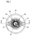
- the preferred embodiment of the reactor 41 shown in Figures 7 to 9 is similar to that shown in Figures 1 and 2 and comprises a cylindrical mixing tank 43 containing the slurry, a vertical draft tube 45 submerged in the slurry which divides the tank 43 into an inner chamber 89 and outer chambers 91, a motor driven axial flow impeller 47 located in the draft tube 45 near the top thereof, and an aerator assembly, generally identified by the numeral 49, supported by any suitable means (not shown) to extend into the tank 43.
- the aerator assembly 49 comprises a venturi aerator 63 located directly above the draft tube 45, two inlets 51 located adjacent the side wall of the tank 43, and a motor driven axial flow pump 61 located in each inlet 51.
- the aerator assembly 49 further comprises channels 53 which connect the inlets 51 to the venturi aerator 63.
- the venturi aerator 63 comprises an annular array of aerators 57 which are the same basic construction as the aerators 38 shown in Figures 3 and 4 separated by air delivery channels 81.
- the aerators 57 are arranged so that the elongate throat regions 83 extend radially and the open ends of the air delivery channels 81 form part of the outer and inner sides 113, 115 of the venturi aerator 63. With such an arrangement air can flow with unrestricted access through the open ends into the air delivery channels 81 and then through the openings (not shown) in the air delivery channels 81 into the throat regions 83 of the aerators 57.
- the preferred embodiments of the reactors shown in the drawings have low head requirements and low friction losses in the aerator assemblies.
- the reactors can operate efficiently with low head axial flow pumps whereas centrifugal pumps, which are commonly used to pump fluids, would operate less efficiently.
- the reactors allow the axial flow pumps to operate at low impeller tip speeds which is important in a mineral slurry to avoid excessive wear.
- the power requirements to operate the impellers to draw the slurry into and through the aerator assemblies are significantly lower than to pump the slurry through the external circuit disclosed in International application PCT/AU92/00645.
- the reactors are capable of allowing a large volume of fluid to be circulated in the mixing tank and aerated with a large volume of air by natural aspiration.
- cylindrical draft tubes 45 located centrally in a cylindrical mixing tanks 12,43 to divide the mixing tanks 12,43 into inner chambers 21,89 and outer annular chambers 23, 91
- the invention is not so restricted and extends to any configuration of partition means to divide a mixing tank into at least two chambers through which fluid can circulate.
- aerator assemblies 29, 49 of the preferred embodiments comprise throat regions 143, 83 which have a uniform with W, it can readily be appreciated that the invention is not so restricted.
- the preferred embodiment shown in Figures 7 to 9 comprises a plurality of aerators 57 arranged side by side in an annular array so that the elongate throat regions 83 extend radially and the air delivery channels 81 are of truncated wedge-shaped configuration
- the invention is not so restricted and extends to any other suitable arrangement.
- the aerators 57 may be arranged side by side in banks in which the aerators 57 of each bank are parallel and the banks are positioned in an annular array so that the elongate throat regions 83 extend generally radially.
- the banks of parallel aerators 57 may be arranged in an annular array so that the elongate throat regions 83 extend transversely to a radial axis.
- channels 35, 53 of the aerator assemblies 29, 49 of the preferred embodiments are shown as fully enclosed units, it can readily be appreciated that the invention is not so restricted and the channels may be open-topped or otherwise vented to allow separation from the fluid of gases that are evolved or produced in a mixing tank.
Abstract
Description
- The invention relates to a reactor for a two-phase or a three-phase system.
- The invention has particular application to the aeration of a fluid comprising a slurry of mineral particles with a gas comprising air or any other suitable oxygen-containing gas. However, the invention is not restricted to this application and extends to the aeration of any gas/liquid, gas/liquid/solid or gas/liquid/solid/microbial systems.
- The term "aeration" is understood to mean herein the injection of a gas or gases into a fluid.
- International application PCT/AU92/00645 entitled "Reactor" lodged on 2 December 1992 in the name of the applicant discloses a reactor for aerating a fluid with a gas.
- The reactor comprises a mixing tank for the fluid, a centrally located draft tube that partitions the mixing tank into a central chamber and an annular chamber which are in fluid communication at upper and lower regions of the mixing tank, and an axial flow pump located in the draft tube for circulating the fluid downwards in the draft tube and upwards in the annular chamber. The reactor also comprises an external circuit that removes a sidestream of the fluid from the mixing tank, aerates the fluid, and returns the aerated fluid to the mixing tank. The external circuit comprises an aerator in the form of a venturi of frusto-conical design having holes or a porous membrane in the region of the throat of the venturi for introducing the gas into the fluid. The aerator takes advantage of the fact that the fluid pressure in the throat region of the venturi is less than that upstream and downstream of the throat regiom and enables the air to be introduced into the liquor by natural aspiration or at low pressure. The external circuit further comprises a centrifugal pump for pumping the fluid around the external circuit.
- The reactor disclosed in the International application is an effective means of aerating a fluid. This is reflected in the experimental results in the International application which show a decrease in power requirements with the reactor when compared with a conventional air agitated reactor.
- An object of the present invention is to provide a reactor for introducing a gas into a fluid which is capable of achieving a further significant decrease in power requirements when compared with the reactor disclosed in International application PCT/AU92/00645.
- Reference is also made to EP-A-0 071 767, which teaches an aeration device similar to that disclosed herein. This device employs a porous element for the purpose of aeration instead of a venturi.
- According to one aspect of the invention there is provided a reactor for introducing a gas into a fluid which is a liquid, liquid/solid or liquid/solid/microbial system comprising a mixing tank for the fluid, a partition means for dividing the tank into two chambers, such that a first pump means located in one of the chambers circulates the fluid downwards in one chamber and then upwards in the other chamber, an aerator assembly for aerating a sidestream of the fluid and introducing the aerated fluid into the tank for mixing the aerated fluid with the circulating fluid in the tank, the aerator assembly being located in an upper region of the tank and comprising a venturi aerator having:
- (a) an aerator inlet;
- (b) an aerator outlet;
- (c) a constriction intermediate the aerator inlet and the aerator outlet for creating a region of reduced pressure in the fluid, the constriction being elongate in a section transverse to the direction of flow of the fluid through the constriction; and
- (d) a means for introducing the gas into the constriction to aerate the fluid.
- The term "elongate" as used herein is understood to mean that the ratio of the length and width dimensions of the constriction be at least 1.5:1.
- Another aspect of the invention comprehends the use of a reactor as aforesaid for aerating liquid, liquid/solid and liquid/solid/microbial systems.
- The invention is described further with reference to the accompanying drawings in which:
- Figure 1 represents schematically one preferred embodiment of a reactor formed in accordance with the invention;
- Figure 2 is a detailed schematic representation of the aerator assembly of the reactor shown in Figure 1;
- Figure 3 is an enlarged section along the line 3-3 in Figure 2;
- Figure 4 is an enlarged section along the line 4-4 in Figure 2;
- Figure 5 is a graph of power requirements versus air flow rate for an experimental reactor of the general type shown in Figures 1 to 4;
- Figure 6 is graph of air flow rate versus liquor flow rate for a venturi aerator having an elongate slot configuration in the throat region in the reactor of the type shown in Figures 1 to 4 and a conventional venturi aerator having a circular configuration in the throat region;
- Figure 7 is a top plan view of another preferred embodiment of a reactor formed in accordance with the invention; and
- Figure 8 is a section along the line 8-8 in Figure 7; and
- Figure 9 is an enlarged partial section of the throat region of the aerator assembly along the line 9-9 of Figure 8.
- The preferred embodiments of the reactor of the invention are described herein in relation to the aeration of a slurry of a mineral and water with air. However, it is noted that the invention is not restricted to this application and extends to the gasification of any fluid which is a liquid, liquid/solid or liquid/solid/microbial system.
- The preferred embodiment of the
reactor 11 shown in Figures 1 and 2 comprises acylindrical mixing tank 12 containing the slurry, avertical draft tube 13 submerged in the slurry, and a motor drivenaxial flow impeller 14 located in thedraft tube 13 near the top thereof. - The
tank 12 may be of any suitable size. Thedraft tube 13 has open upper andlower ends mixing tank 12 to divide themixing tank 12 into aninner chamber 21 and an outerannular chamber 23. In use, theimpeller 14 induces a flow of the slurry downwards in thedraft tube 13 and then upwards in the outerannular chamber 23, as indicated by the arrows in the figure. The flow of the slurry is controlled so that the mineral particles are kept in suspension. - The
reactor 11 further comprises an aerator assembly, generally identified by thenumeral 29, supported by any suitable means (not shown) to extend into an upper region of thetank 12. - The
aerator assembly 29 comprises aninlet 31 for slurry located in thetank 12 adjacent the side wall of thetank 12 and a motor drivenaxial flow impeller 33 located in theinlet 31 for drawing a portion of the slurry circulating upwardly in theouter chamber 23 of thetank 12 through theinlet 31 into theaerator assembly 29. Achannel 35 connects theinlet 31 to aventuri aerator 37 located generally above thedraft tube 13 so that aerated slurry from theventuri aerator 37 discharges into thetank 12 upstream of theimpeller 14 and thereafter flows downwardly in thedraft tube 13 and mixes with the circulating slurry. - With reference to Figures 3 and 4, the
venturi aerator 37 comprises a bank of fouraerators 38 arranged in parallel with acommon inlet 117, which is an extension of thechannel 35, and acommon outlet 119 for the aerated fluid. Theaerators 38 are separated by a series of three parallel open endedair delivery channels 23 which are generally diamond-shaped in transverse section. - With reference to Figure 4, the
air delivery channels 23 are open-ended so that air can flow without restriction into thechambers 25, as indicated by the arrows in the figure. - With reference to Figure 3, each
aerator 38 comprises aninlet region 141 which tapers inwardly from theinlet 117, athroat region 143, and anoutlet region 145 which tapers outwardly towards theoutlet 119. - With reference to Figure 4, each
throat region 143 is in the form of an elongate slot of length L and width W in a section transverse to the direction of flow of the fluid through theaerator 38. - The throat length L and throat width W may be of any suitable dimensions. In this context the dimensions are dependent on a number of factors including, but not limited to, the size and operating parameters of the reactor, and the aeration requirements of the fluid. By way of example, the ratio of L:D may be 10:1 for some situations, 100:1 in other situations, and 500:1 or more in other situations.
- As is readily apparent from Figure 3, the cross-sectional area of the
throat region 143 is less than that of theinlet region 141 and theoutlet region 145 so that fluid flowing through thethroat region 143 is subject to a venturi effect with the result that, in accordance with the Bernoulli equations, the fluid pressure in thethroat region 143 is less than that in theinlet region 141 and theoutlet region 145. - With reference to Figures 3 and 4, each
aerator 38 further comprises a plurality ofholes 25 in thewalls 167 of theair delivery chambers 23 and theside walls 161 of theventuri aerator 37 for introducing air into thethroat regions 143 of theaerators 38 to aerate the fluid flowing through thethroat regions 143. In view of the reduced fluid pressure in thethroat regions 141 the air may be introduced by natural aspiration or at low pressure thereby minimising capital and operating costs of theaerator assembly 37. Theholes 25 are located at spaced intervals substantially around the perimeter of thethroat regions 143 to maximise contact between the air and the fluid flowing through thethroat regions 143. In addition, in any given situation, the width W of thethroat regions 143 is selected to minimise the ineffective zone in the fluid in the central region of thethroat regions 143 where there is neglible penetration of the air entering throughholes 25 and therefore minimal if any gas fluid contact. It is noted that, effective gas fluid contact occurs relatively close to where the gas is admitted. - It has been found by the applicant in a series of experiments to aerate an aqueous leach liquor with air that the power requirements to operate the
axial flow impellers - The series of experiments was carried out on a 30 m3 reactor of the type shown in Figures 1 to 4 having a bank of six rather than four
aerators 38. Theaerators 38 had a throat width W of 9 mm and a throat length L of 296 mm. - The results of the experiments are shown in Figure 5. Figure 5 is a plot of the relationship between the power consumed by the
axial flow impellers 14,33 (in terms of Wh/m3 of air entrained) versus the air entrained. On the basis of the results shown in Figure 5 and on power requirement calculations, the applicant believes that the power requirements for a full scale commercial reactor would be less than 10 Wh/m3. - It has also been found unexpectedly by the applicant in a series of experiments to aerate an aqueous leach liquor with air with venturi aerators that as the flow rate of the liquor increases it is possible to introduce significantly higher amounts of air into the liquor with aerators which have an elongate slot configuration in the throat region, such as the
aerators 38 shown in Figures 3 and 4, than with conventional aerators which have a throat region of circular cross-section. - The experiments were carried out on an aerator of the basic construction of the
aerators 38 shown in Figures 3 and 4 having a throat width W of 9 mm, throat length L of 200 mm, and 384 holes of 1 mm diameter and 3 conventional aerators having: - (a) a throat diameter of 25 mm and 96 holes of 1 mm diameter;
- (b) a throat diameter of 18 mm and 48 holes of 1 mm diameter; and
- (c) a throat diameter of 36 mm and 72 holes of 1 mm diameter.
- The results of the experiments are shown in Figure 6. Figure 6 is a plot of the relationship of the air flow rate that could be drawn by natural aspiration into the aerators against the flow rate of liquor through the aerators. The dotted lines on the figure represent 0.1 increments of the volume ratio of air flow rate to liquor flow rate. The air to liquor ratio is a measure of the efficiency of the aerators.
- Figure 6 shows that the air flow rate that was drawn by natural aspiration of the aerator 38 (referred to as "trough aerator" in the figure) increased linearly with the flow rate of liquor through the
aerator 38, whereas the air flow rate that was drawn by natural aspiration into the conventional aerators (referred to as "conical aerators" in the figure) levelled off at relatively low liquor flow rates. - In addition, Figure 6 shows that the air to liquor ratio of the
aerator 38, particularly at high liquor flow rates, was considerably higher than that of the conventional aerators and the difference in efficiency of the aerators, as reflected by this parameter, became increasingly marked as the liquor flow rate increased. The relatively high air to liquor ratio, particularly at high liquor flow rates, is an important feature of theaerator 38 because it enables the capital and operating costs associated with aeration to be minimised. - The preferred embodiment of the reactor 41 shown in Figures 7 to 9 is similar to that shown in Figures 1 and 2 and comprises a
cylindrical mixing tank 43 containing the slurry, avertical draft tube 45 submerged in the slurry which divides thetank 43 into aninner chamber 89 andouter chambers 91, a motor drivenaxial flow impeller 47 located in thedraft tube 45 near the top thereof, and an aerator assembly, generally identified by the numeral 49, supported by any suitable means (not shown) to extend into thetank 43. - The
aerator assembly 49 comprises aventuri aerator 63 located directly above thedraft tube 45, twoinlets 51 located adjacent the side wall of thetank 43, and a motor drivenaxial flow pump 61 located in eachinlet 51. Theaerator assembly 49 further compriseschannels 53 which connect theinlets 51 to theventuri aerator 63. - With reference to Figures 7 and 9, the
venturi aerator 63 comprises an annular array ofaerators 57 which are the same basic construction as theaerators 38 shown in Figures 3 and 4 separated byair delivery channels 81. Theaerators 57 are arranged so that theelongate throat regions 83 extend radially and the open ends of theair delivery channels 81 form part of the outer andinner sides venturi aerator 63. With such an arrangement air can flow with unrestricted access through the open ends into theair delivery channels 81 and then through the openings (not shown) in theair delivery channels 81 into thethroat regions 83 of theaerators 57. - The preferred embodiments of the reactors shown in the drawings have low head requirements and low friction losses in the aerator assemblies. As a consequence, the reactors can operate efficiently with low head axial flow pumps whereas centrifugal pumps, which are commonly used to pump fluids, would operate less efficiently. In addition, the reactors allow the axial flow pumps to operate at low impeller tip speeds which is important in a mineral slurry to avoid excessive wear. Specifically, it has been found by the applicant that the power requirements to operate the impellers to draw the slurry into and through the aerator assemblies are significantly lower than to pump the slurry through the external circuit disclosed in International application PCT/AU92/00645.
- Other advantages of the invention are that the reactors are compact and self-contained and the aerator assemblies are readily accessible for maintenance.
- In addition, the reactors are capable of allowing a large volume of fluid to be circulated in the mixing tank and aerated with a large volume of air by natural aspiration.
- Whilst the preferred embodiments comprise
cylindrical draft tubes 45 located centrally in acylindrical mixing tanks tanks inner chambers annular chambers - Furthermore, whilst the preferred embodiment shown in Figures 1 to 4 comprises a bank of four
aerators 38 arranged side by side, it can readily be appreciated that the invention is not so restricted and extends to any suitable number ofaerators 38 arranged in any suitable configuration. - Furthermore, whilst the
aerator assemblies throat regions - Furthermore, whilst the preferred embodiment shown in Figures 7 to 9 comprises a plurality of
aerators 57 arranged side by side in an annular array so that theelongate throat regions 83 extend radially and theair delivery channels 81 are of truncated wedge-shaped configuration, it can readily be appreciated that the invention is not so restricted and extends to any other suitable arrangement. For example, theaerators 57 may be arranged side by side in banks in which theaerators 57 of each bank are parallel and the banks are positioned in an annular array so that theelongate throat regions 83 extend generally radially. By way of further example, the banks ofparallel aerators 57 may be arranged in an annular array so that theelongate throat regions 83 extend transversely to a radial axis. - Furthermore, whilst the
channels aerator assemblies
Claims (28)
- A reactor for introducing a gas into a fluid which is a liquid, liquid/solid or liquid/solid/microbial system, comprising a mixing tank for the fluid, a partition means for dividing the tank into two chambers, such that a first pump means located in one of the chambers may circulate the fluid downwards in one chamber and then upwards in the other chamber, an aerator assembly for aerating a sidestream of the fluid and introducing the aerated fluid into the tank for mixing the aerated fluid with the circulating fluid in the tank, the aerator assembly being located in an upper region of the tank characterised in that it comprises a venturi aerator having:(a) an aerator inlet;(b) an aerator outlet;(c) a constriction intermediate the aerator inlet and the aerator outlet for creating a region of reduced pressure in the fluid, the constriction being elongate, the ratio of its length to width being at least 1.5:1, in a section transverse to the direction of flow of the fluid through the constriction; and(d) a means for introducing the gas into the constriction to aerate the fluid.
- The reactor defined in claim 1 wherein the means for introducing the gas into the constriction comprises an array of jets or holes or a porous membrane in a wall of the constriction.
- The reactor defined in claim 2, wherein the array of jets or holes and the porous membrane extends substantially around the perimeter of the constriction.
- The reactor defined in any one of the preceding claims, wherein the aerator assembly further comprises a second pump means for circulating the sidestream of the fluid from the tank through the aerator.
- The reactor defined in any one of the preceding claims, wherein the aerator assembly further comprises an aerator assembly inlet located adjacent a side wall of the tank.
- The reactor defined in claim 5, wherein the second pump means is located in the aerator assembly inlet.
- The reactor defined in any one of the preceding claims, wherein the aerator assembly comprises a plurality of the aerators arranged side by side.
- The aerator defined in claim 7, wherein the aerator assembly further comprises a gas delivery channel positioned between adjacent constrictions of the aerators to deliver the gas to the means for introducing the gas into the constrictions.
- The reactor defined in claim 7 or claim 8, wherein the aerators are arranged side by side in an annular array.
- The reactor defined in any one of claims 7 to 9, wherein the inlet of each aerator is common to the aerators.
- The reactor defined in any one of the preceding claims, wherein the partition means divides the tank into an inner chamber and an outer chamber.
- The reactor defined in claim 11, wherein the first pump means is located in an upper section of the inner chamber.
- The reactor defined in claim 12, wherein the first pump means comprises an axial flow impeller.
- The reactor defined in claim 13, wherein the impeller is operable to circulate the fluid downwardly in the inner chamber and upwardly in the outer chamber.
- Use, in aerating a fluid which is a liquid, liquid/solid or liquid/solid/microbial system with a gas, of a reactor in accordance with any of claims 1 to 14.
- Use according to claim 15, comprising pumping the fluid through an aerator assembly comprising, (a) a plurality of venturi aerators arranged side by side, each venturi aerator defining one region of reduced fluid pressure, and (b) a plurality of gas delivery channels positioned between the venturi aerators for delivering the gas to the regions of reduced fluid pressure.
- Use according to claim 16 wherein the venturi aerators are arranged in an annular array.
- Use according to any one of claims 15 to 17 further comprising controlling the fluid to flow vertically through the region of reduced fluid pressure.
- Use according to any one of claims 15 to 18, wherein the fluid is an aqueous leach liquor and the gas is air.
- Use according to any one of claims 16 to 19, wherein the volume ratio of the air flow rate to the liquor flow rate is at least 0.1.
- Use according to claim 20, wherein the volume ratio of the air flow rate to the liquor flow rate is at least 0.2.
- Use according to claim 21, wherein the volume ratio of the air flow rate to the liquor flow rate is at least 0.3.
- Use according to claim 22, wherein the volume ratio of the air flow rate to the liquor flow rate is at least 0.5.
- Use according to claim 23, wherein the volume ratio of the air flow rate and the liquor flow rate is at least 0.7.
- Use according to any one of claims 16 to 24, wherein the linear velocity of the liquor through the region of reduced fluid pressure is in the range of 1 to 10 metres/second.
- Use according to claim 25, wherein the linear velocity of the liquor through the region of reduced fluid pressure is in the range of 1 to 5 metres/second.
- Use according to claim 25, wherein the linear velocity of the liquor through the region of reduced fluid pressure is in the range of 3 to 4 metres/second.
- Use according to any one of claims 16 to 26 comprising, introducing the gas into the fluid by natural aspiration or at low pressure.
Applications Claiming Priority (5)
| Application Number | Priority Date | Filing Date | Title |
|---|---|---|---|
| AUPL343792 | 1992-07-09 | ||
| AUPL343692 | 1992-07-09 | ||
| AUPL3436/92 | 1992-07-09 | ||
| AUPL3437/92 | 1992-07-09 | ||
| PCT/AU1993/000340 WO1994001210A1 (en) | 1992-07-09 | 1993-07-09 | A reactor |
Publications (3)
| Publication Number | Publication Date |
|---|---|
| EP0606432A1 EP0606432A1 (en) | 1994-07-20 |
| EP0606432A4 EP0606432A4 (en) | 1994-11-30 |
| EP0606432B1 true EP0606432B1 (en) | 1997-03-12 |
Family
ID=25644288
Family Applications (1)
| Application Number | Title | Priority Date | Filing Date |
|---|---|---|---|
| EP93915520A Expired - Lifetime EP0606432B1 (en) | 1992-07-09 | 1993-07-09 | A reactor |
Country Status (12)
| Country | Link |
|---|---|
| US (1) | US5512217A (en) |
| EP (1) | EP0606432B1 (en) |
| JP (1) | JP3204978B2 (en) |
| KR (1) | KR100301612B1 (en) |
| AT (1) | ATE149876T1 (en) |
| BR (1) | BR9305579A (en) |
| CA (1) | CA2116248C (en) |
| DE (1) | DE69308802T2 (en) |
| FI (1) | FI104470B (en) |
| NZ (1) | NZ253976A (en) |
| RU (1) | RU2139132C1 (en) |
| WO (1) | WO1994001210A1 (en) |
Cited By (1)
| Publication number | Priority date | Publication date | Assignee | Title |
|---|---|---|---|---|
| SG132571A1 (en) * | 2001-12-19 | 2007-06-28 | Anatoly Anatolyevich Kutyev | Personal device for spumescent oxygen cocktail preparation and its gas bottle |
Families Citing this family (10)
| Publication number | Priority date | Publication date | Assignee | Title |
|---|---|---|---|---|
| AUPO129096A0 (en) * | 1996-07-26 | 1996-08-22 | Boc Gases Australia Limited | Oxygen dissolver for pipelines or pipe outlets |
| KR200187153Y1 (en) * | 1997-08-27 | 2000-07-01 | 윤종용 | Condenser for a vapor collecting device in an image forming apparatus |
| AU2132901A (en) | 1999-11-30 | 2001-06-12 | Gerard Van Dijk | Apparatus for mixing and aerating liquid-solid slurries |
| US6530895B1 (en) | 2000-01-25 | 2003-03-11 | Life International Products, Inc. | Oxygenating apparatus, method for oxygenating a liquid therewith, and applications thereof |
| AU9348601A (en) | 2000-09-26 | 2002-04-08 | Tech Resources Pty Ltd | Upgrading solid material |
| FR2823742B1 (en) * | 2001-04-19 | 2004-03-12 | Alain Boulant | DEVICE FOR BREWING AND AERATING A LIQUID IN A TREATMENT TANK |
| FR2823743B1 (en) * | 2001-04-19 | 2004-03-12 | Alain Boulant | DEVICE FOR BREWING AND AERATING A LIQUID IN A TREATMENT TANK |
| ES2553589T3 (en) * | 2009-05-04 | 2015-12-10 | Paques I.P. B.V. | Bioreactor comprising a mixing chamber |
| US8673246B2 (en) * | 2011-03-23 | 2014-03-18 | Uop Llc | Process for contacting one or more fluids and a reactor relating thereto |
| RU2516572C1 (en) * | 2012-12-28 | 2014-05-20 | Открытое акционерное общество "Воскресенские минеральные удобрения" | Reactor for conducting chemical processes accompanied by foam abundance |
Family Cites Families (55)
| Publication number | Priority date | Publication date | Assignee | Title |
|---|---|---|---|---|
| US897735A (en) * | 1906-01-23 | 1908-09-01 | Firm Of Chem Fab Floersheim Dr H Noerdlinger | Process of freeing waste waters containing cyanids and sulfocyanids from poison. |
| US1808956A (en) * | 1930-06-17 | 1931-06-09 | Schutte & Koerting Co | Apparatus for and method of combining liquids and gases |
| BE505351A (en) * | 1950-08-23 | |||
| US2708571A (en) * | 1951-05-29 | 1955-05-17 | Industrikemiska Ab | Method and apparatus for contacting gases and liquids |
| US3350302A (en) * | 1964-09-16 | 1967-10-31 | Nikex Nehezipari Kulkere | Clarification of surface waters |
| DE1584885A1 (en) * | 1965-09-14 | 1970-02-05 | Danjes Dipl Ing Martin | Device for the biological cleaning of waste water |
| US3371618A (en) * | 1966-02-18 | 1968-03-05 | Chambers John | Pump |
| DE1940458B2 (en) * | 1968-08-12 | 1972-02-17 | Miejskie Przedsiebiorstwo Wodociagow i Kanaliczacji, Czestochowa (Polen) | METHOD AND DEVICE FOR GASIFYING A LIQUID |
| AT288294B (en) * | 1968-11-20 | 1971-02-25 | Vogelbusch Gmbh | Device for gassing liquids |
| DE1906051A1 (en) * | 1969-02-07 | 1970-08-27 | Basf Ag | Process for the production of alkynols or alkynediols |
| US3592586A (en) * | 1969-02-17 | 1971-07-13 | Franke Plating Works | Method for treating cyanide wastes |
| NL6910591A (en) * | 1969-07-10 | 1971-01-12 | ||
| US3680698A (en) * | 1970-02-25 | 1972-08-01 | Occidental Petroleum Corp | Process for the treatment of slimes and waste solids |
| US3927152A (en) * | 1971-03-12 | 1975-12-16 | Fmc Corp | Method and apparatus for bubble shearing |
| BE790132R (en) * | 1971-10-14 | 1973-04-16 | Basf Ag | PROCESS AND DEVICE FOR VENTILATION |
| US4017565A (en) * | 1973-07-13 | 1977-04-12 | Mueller Hans | Device for admixing a gaseous and a liquid phase |
| AU497149B2 (en) * | 1973-09-27 | 1978-12-07 | The Commonwealth Industrial Gases Limited | Dissolving gas ina liquid |
| US4051204A (en) * | 1973-12-21 | 1977-09-27 | Hans Muller | Apparatus for mixing a liquid phase and a gaseous phase |
| US3932275A (en) * | 1974-08-29 | 1976-01-13 | Amax Resource Recovery Systems, Inc. | Process for the treatment of mineral slimes |
| US4193950A (en) * | 1975-07-04 | 1980-03-18 | Linde Aktiengesellschaft | Apparatus for introducing gas into a liquid |
| GB1484657A (en) * | 1975-08-19 | 1977-09-01 | Kamelmacher E | Liquid treatment plants and methods for their operation |
| GB1531015A (en) * | 1975-10-31 | 1978-11-01 | Laurie A | Aeration and mixing of liquids |
| GB1591104A (en) * | 1976-11-18 | 1981-06-17 | Boc Ltd | Treatment of sewage in a sewer by oxygenation |
| GB1568820A (en) * | 1976-01-12 | 1980-06-04 | Boc Ltd | Dissolving gas in liquid |
| FR2338071A1 (en) * | 1976-01-16 | 1977-08-12 | Cem Comp Electro Mec | METHOD AND DEVICE FOR THE FORMATION OF GAS BUBBLES, FOR EXAMPLE WITH A VIEW OF FLOTATION |
| GB1524765A (en) * | 1976-02-27 | 1978-09-13 | Unisearch Ltd | Process and apparatus for the aerobic biological purification of liquid wastes containing organic pollutants |
| CA1097605A (en) * | 1976-05-03 | 1981-03-17 | Donald E. Weiss | Water clarification |
| GB2013095B (en) * | 1977-09-12 | 1982-03-10 | Boc Ltd | Dissolving gas in a liquid |
| GB2011369B (en) * | 1977-09-12 | 1982-03-10 | Boc Ltd | Treatment of aqueous waste material |
| US4521307A (en) * | 1977-11-04 | 1985-06-04 | Reid John H | Conservation of momentum in a barrier oxidation ditch |
| US4290885A (en) * | 1977-12-22 | 1981-09-22 | Dochan Kwak | Aeration device |
| GB1597391A (en) * | 1978-01-25 | 1981-09-09 | American Water Recycling Co | Apparatus and method for treating sewage |
| GB2037174A (en) * | 1978-12-15 | 1980-07-09 | Venturator Systems Ltd | Apparatus for the gasification of liquids |
| US4267052A (en) * | 1979-12-10 | 1981-05-12 | Chang Shih Chih | Aeration method and apparatus |
| EP0042396A1 (en) * | 1979-12-18 | 1981-12-30 | BOC Limited | Method and apparatus for dissolving gas in a liquid |
| GB2072027B (en) * | 1980-01-30 | 1983-04-07 | Water Res Centre | Transfer of oxygen into wastewater |
| FR2484447A1 (en) * | 1980-06-13 | 1981-12-18 | Saps Anticorrosion | AEROBIC BIOTRANSFORMATION METHOD AND DEVICE |
| US4483826A (en) * | 1980-08-12 | 1984-11-20 | Phillips Petroleum Company | Combination reaction vessel and aspirator-mixer |
| JPS5814910A (en) * | 1981-07-20 | 1983-01-28 | Kubota Ltd | Flocculating and precipitating method |
| DE3130597C2 (en) * | 1981-08-01 | 1986-07-24 | Klöckner-Werke AG, 4100 Duisburg | Method and device for gassing a liquid |
| US4465597B2 (en) * | 1981-08-10 | 1997-07-01 | Tetra Tech | Treatment of industrial wastewaters |
| GB2107696B (en) * | 1981-10-16 | 1985-01-09 | Geoffrey John Hamilton Mcbride | Improvements relating to sewage disposal systems |
| GB2118449B (en) * | 1981-11-06 | 1985-09-25 | Boc Group Plc | Dissolving gas in a liquid |
| GB8315381D0 (en) * | 1983-06-03 | 1983-07-06 | Boc Group Plc | Liquid phase oxidation |
| SE442173B (en) * | 1983-10-27 | 1985-12-09 | Sunds Defibrator | DEVICE FOR FLOTATION OF FIBER SUSPENSIONS |
| GB2179647B (en) * | 1985-05-21 | 1989-11-01 | Boc Group Plc | Treatment of sewage |
| BR8503919A (en) * | 1985-08-16 | 1987-03-24 | Liquid Carbonic Ind Sa | EJECTOR FOR THE CO2 PROCESS IN THE ALKALINE WATER NEUTRALIZATION |
| DE3536057A1 (en) * | 1985-10-09 | 1987-04-16 | Gerhard Velebil | METHOD AND DEVICE FOR MAINTAINING A LIQUID GAS DISPERSION |
| FR2589460B1 (en) * | 1985-10-30 | 1991-02-15 | Dodier Jacques | HYDROKINETIC INJECTION TREATMENT DEVICE, PARTICULARLY FOR WASTE WATER |
| IT209447Z2 (en) * | 1985-12-04 | 1988-10-10 | Varisco Pompe Spa | DEVICE FOR THE OXYGENATION OF LIQUAMS. |
| GB8717098D0 (en) * | 1987-07-20 | 1987-08-26 | Water Res Centre | Thermophilic aerobic digestion |
| US5043104A (en) * | 1987-11-04 | 1991-08-27 | Barrett Haentjens & Co. | Apparatus for gas absorption in a liquid |
| GB8921454D0 (en) * | 1989-09-22 | 1989-11-08 | Thames Water Plc | Oxygenation |
| US5004571A (en) * | 1990-03-30 | 1991-04-02 | Union Carbide Industrial Gases Technology Corporation | Liquid level control in gas-liquid mixing operations |
| US5108662A (en) * | 1991-05-01 | 1992-04-28 | Union Carbide Industrial Gases Technology Corporation | Gas-liquid mixing process and apparatus |
-
1993
- 1993-07-09 US US08/196,132 patent/US5512217A/en not_active Expired - Lifetime
- 1993-07-09 DE DE69308802T patent/DE69308802T2/en not_active Expired - Fee Related
- 1993-07-09 BR BR9305579A patent/BR9305579A/en not_active IP Right Cessation
- 1993-07-09 JP JP50277194A patent/JP3204978B2/en not_active Expired - Fee Related
- 1993-07-09 CA CA002116248A patent/CA2116248C/en not_active Expired - Fee Related
- 1993-07-09 EP EP93915520A patent/EP0606432B1/en not_active Expired - Lifetime
- 1993-07-09 WO PCT/AU1993/000340 patent/WO1994001210A1/en active IP Right Grant
- 1993-07-09 NZ NZ253976A patent/NZ253976A/en not_active IP Right Cessation
- 1993-07-09 AT AT93915520T patent/ATE149876T1/en not_active IP Right Cessation
- 1993-07-09 KR KR1019940700768A patent/KR100301612B1/en not_active IP Right Cessation
- 1993-07-09 RU RU94020399A patent/RU2139132C1/en not_active IP Right Cessation
-
1994
- 1994-03-08 FI FI941080A patent/FI104470B/en active
Cited By (1)
| Publication number | Priority date | Publication date | Assignee | Title |
|---|---|---|---|---|
| SG132571A1 (en) * | 2001-12-19 | 2007-06-28 | Anatoly Anatolyevich Kutyev | Personal device for spumescent oxygen cocktail preparation and its gas bottle |
Also Published As
| Publication number | Publication date |
|---|---|
| FI104470B (en) | 2000-02-15 |
| DE69308802T2 (en) | 1997-06-19 |
| DE69308802D1 (en) | 1997-04-17 |
| WO1994001210A1 (en) | 1994-01-20 |
| CA2116248A1 (en) | 1994-01-20 |
| RU2139132C1 (en) | 1999-10-10 |
| NZ253976A (en) | 1997-01-29 |
| CA2116248C (en) | 2004-11-09 |
| EP0606432A1 (en) | 1994-07-20 |
| EP0606432A4 (en) | 1994-11-30 |
| BR9305579A (en) | 1996-01-02 |
| JP3204978B2 (en) | 2001-09-04 |
| FI941080A0 (en) | 1994-03-08 |
| KR100301612B1 (en) | 2001-12-01 |
| JPH06510235A (en) | 1994-11-17 |
| US5512217A (en) | 1996-04-30 |
| ATE149876T1 (en) | 1997-03-15 |
| FI941080A (en) | 1994-03-08 |
Similar Documents
| Publication | Publication Date | Title |
|---|---|---|
| CN106552560B (en) | A kind of airlift reactor with spiral porous sieve plate | |
| CA1124415A (en) | Fluids mixing apparatus | |
| EP0606432B1 (en) | A reactor | |
| CA1139464A (en) | Multiple stage jet nozzle aeration system | |
| US4267052A (en) | Aeration method and apparatus | |
| US5549818A (en) | Sewage treatment system | |
| US5569416A (en) | Apparatus for aerating fish ponds and lakes | |
| US4455232A (en) | Method and apparatus for induced-flow circulation and pressurized aeration in a barrier oxidation ditch | |
| US6565070B2 (en) | Reactor | |
| CA2101627C (en) | A reactor | |
| US20010006261A1 (en) | Diffused aeration method | |
| EP0027912A1 (en) | Apparatus for contacting liquid with a gas | |
| US4707308A (en) | Apparatus for circulating water | |
| US4166790A (en) | Single stage process for continuous introduction of oxygen-containing gases into effluent containing activated sludge | |
| US4585555A (en) | Barrier oxidation ditch having increased flow efficiency and oxygen transfer efficiency | |
| US6193220B1 (en) | Diffused aeration system | |
| AU665266B2 (en) | A reactor | |
| EP0027911A1 (en) | Apparatus for contacting liquid with a gas | |
| US4917832A (en) | Air lift diffuser | |
| WO2000027514A1 (en) | Ejector for entraining a gas into a liquid | |
| US3976575A (en) | Liquid aeration device | |
| CN215161366U (en) | Micro-interface reinforced biochemical aeration system | |
| RU2021347C1 (en) | Apparatus for gas saturation and mixing liquid in reservoir | |
| PL89647B1 (en) | Apparatus for the gasification of liquids [gb1449889a] | |
| RU2081578C1 (en) | Aerator and fermenter with aerating and fermenting apparatus |
Legal Events
| Date | Code | Title | Description |
|---|---|---|---|
| PUAI | Public reference made under article 153(3) epc to a published international application that has entered the european phase |
Free format text: ORIGINAL CODE: 0009012 |
|
| AK | Designated contracting states |
Kind code of ref document: A1 Designated state(s): AT BE DE DK ES FR GB SE |
|
| 17P | Request for examination filed |
Effective date: 19940623 |
|
| A4 | Supplementary search report drawn up and despatched |
Effective date: 19941011 |
|
| AK | Designated contracting states |
Kind code of ref document: A4 Designated state(s): AT BE DE DK ES FR GB SE |
|
| 17Q | First examination report despatched |
Effective date: 19950428 |
|
| GRAG | Despatch of communication of intention to grant |
Free format text: ORIGINAL CODE: EPIDOS AGRA |
|
| GRAH | Despatch of communication of intention to grant a patent |
Free format text: ORIGINAL CODE: EPIDOS IGRA |
|
| GRAH | Despatch of communication of intention to grant a patent |
Free format text: ORIGINAL CODE: EPIDOS IGRA |
|
| GRAA | (expected) grant |
Free format text: ORIGINAL CODE: 0009210 |
|
| AK | Designated contracting states |
Kind code of ref document: B1 Designated state(s): AT BE DE DK ES FR GB SE |
|
| PG25 | Lapsed in a contracting state [announced via postgrant information from national office to epo] |
Ref country code: ES Free format text: THE PATENT HAS BEEN ANNULLED BY A DECISION OF A NATIONAL AUTHORITY Effective date: 19970312 Ref country code: DK Effective date: 19970312 |
|
| REF | Corresponds to: |
Ref document number: 149876 Country of ref document: AT Date of ref document: 19970315 Kind code of ref document: T |
|
| REF | Corresponds to: |
Ref document number: 69308802 Country of ref document: DE Date of ref document: 19970417 |
|
| ET | Fr: translation filed | ||
| PLBE | No opposition filed within time limit |
Free format text: ORIGINAL CODE: 0009261 |
|
| STAA | Information on the status of an ep patent application or granted ep patent |
Free format text: STATUS: NO OPPOSITION FILED WITHIN TIME LIMIT |
|
| 26N | No opposition filed | ||
| REG | Reference to a national code |
Ref country code: GB Ref legal event code: IF02 |
|
| PGFP | Annual fee paid to national office [announced via postgrant information from national office to epo] |
Ref country code: DE Payment date: 20080717 Year of fee payment: 16 |
|
| PGFP | Annual fee paid to national office [announced via postgrant information from national office to epo] |
Ref country code: FR Payment date: 20080718 Year of fee payment: 16 Ref country code: AT Payment date: 20080711 Year of fee payment: 16 |
|
| PGFP | Annual fee paid to national office [announced via postgrant information from national office to epo] |
Ref country code: GB Payment date: 20080709 Year of fee payment: 16 |
|
| PGFP | Annual fee paid to national office [announced via postgrant information from national office to epo] |
Ref country code: SE Payment date: 20080709 Year of fee payment: 16 |
|
| PGFP | Annual fee paid to national office [announced via postgrant information from national office to epo] |
Ref country code: BE Payment date: 20090126 Year of fee payment: 16 |
|
| BERE | Be: lapsed |
Owner name: *TECHNOLOGICAL RESOURCES PTY. LTD Effective date: 20090731 |
|
| EUG | Se: european patent has lapsed | ||
| GBPC | Gb: european patent ceased through non-payment of renewal fee |
Effective date: 20090709 |
|
| REG | Reference to a national code |
Ref country code: FR Ref legal event code: ST Effective date: 20100331 |
|
| PG25 | Lapsed in a contracting state [announced via postgrant information from national office to epo] |
Ref country code: FR Free format text: LAPSE BECAUSE OF NON-PAYMENT OF DUE FEES Effective date: 20090731 |
|
| PG25 | Lapsed in a contracting state [announced via postgrant information from national office to epo] |
Ref country code: GB Free format text: LAPSE BECAUSE OF NON-PAYMENT OF DUE FEES Effective date: 20090709 |
|
| PG25 | Lapsed in a contracting state [announced via postgrant information from national office to epo] |
Ref country code: DE Free format text: LAPSE BECAUSE OF NON-PAYMENT OF DUE FEES Effective date: 20100202 Ref country code: BE Free format text: LAPSE BECAUSE OF NON-PAYMENT OF DUE FEES Effective date: 20090731 Ref country code: AT Free format text: LAPSE BECAUSE OF NON-PAYMENT OF DUE FEES Effective date: 20090709 |
|
| PG25 | Lapsed in a contracting state [announced via postgrant information from national office to epo] |
Ref country code: SE Free format text: LAPSE BECAUSE OF NON-PAYMENT OF DUE FEES Effective date: 20090710 |