EP0605960A1 - A technique for reducing echoes in conference communications - Google Patents
A technique for reducing echoes in conference communications Download PDFInfo
- Publication number
- EP0605960A1 EP0605960A1 EP93309758A EP93309758A EP0605960A1 EP 0605960 A1 EP0605960 A1 EP 0605960A1 EP 93309758 A EP93309758 A EP 93309758A EP 93309758 A EP93309758 A EP 93309758A EP 0605960 A1 EP0605960 A1 EP 0605960A1
- Authority
- EP
- European Patent Office
- Prior art keywords
- signal
- echo
- echo canceller
- signal sources
- signals
- Prior art date
- Legal status (The legal status is an assumption and is not a legal conclusion. Google has not performed a legal analysis and makes no representation as to the accuracy of the status listed.)
- Granted
Links
Images


Classifications
-
- H—ELECTRICITY
- H04—ELECTRIC COMMUNICATION TECHNIQUE
- H04M—TELEPHONIC COMMUNICATION
- H04M3/00—Automatic or semi-automatic exchanges
- H04M3/42—Systems providing special services or facilities to subscribers
- H04M3/56—Arrangements for connecting several subscribers to a common circuit, i.e. affording conference facilities
-
- H—ELECTRICITY
- H04—ELECTRIC COMMUNICATION TECHNIQUE
- H04M—TELEPHONIC COMMUNICATION
- H04M3/00—Automatic or semi-automatic exchanges
- H04M3/002—Applications of echo suppressors or cancellers in telephonic connections
-
- H—ELECTRICITY
- H04—ELECTRIC COMMUNICATION TECHNIQUE
- H04M—TELEPHONIC COMMUNICATION
- H04M3/00—Automatic or semi-automatic exchanges
- H04M3/42—Systems providing special services or facilities to subscribers
- H04M3/56—Arrangements for connecting several subscribers to a common circuit, i.e. affording conference facilities
- H04M3/568—Arrangements for connecting several subscribers to a common circuit, i.e. affording conference facilities audio processing specific to telephonic conferencing, e.g. spatial distribution, mixing of participants
-
- H—ELECTRICITY
- H04—ELECTRIC COMMUNICATION TECHNIQUE
- H04M—TELEPHONIC COMMUNICATION
- H04M3/00—Automatic or semi-automatic exchanges
- H04M3/40—Applications of speech amplifiers
Definitions
- the present invention relates to communications systems and, more particularly, to such systems having circuitry for reducing echoes in a conference communications originating from three or more information signal sources.
- Conferencing is the capability in a communications system of coupling information signals among three or more system subscribers.
- the information signals are typically voice signals but, with the advent of multimedia communications capabilities, can also be non-voice signals, i.e., data, video, facsimile and the like.
- Echoes are a major problem in conferencing circuits. When a large number of circuits are interconnected in a conference call, the cumulative effect of many echo paths severely degrades voice quality and circuit instability can render the communications unintelligible.
- Prior art solutions to the problem of echoes have either introduced attenuation into each of the circuits or have provided echo cancellation via circuitry disposed in each of the circuits interconnected in the conference call.
- the former technique limits the maximum number of system users or "conferees" in a conference call while the latter solution to the echo problem is expensive to implement in communications systems. It would, therefore, be desirable if a readily implementable, low-cost echo reduction technique could be provided for conferencing circuitry.
- echoes in a conference call are reduced through the use of an echo canceller which is connected to a signal combiner in a conference bridging circuit.
- the combiner receives the information signals to be conferenced along with an echo compensation signal and provides an output representative of a sum of these signals.
- the echo canceller receives the signal combiner output and provides the echo compensation signal.
- the echo canceller can provide fixed or adaptive echo compensation and, in the latter case, the adaptation can be provided in response to the information signals or to training sequences.
- FIG. 1 A basic representation of a conference bridge 100 is shown in FIG. 1.
- Bridge 100 provides illustrative voice conferencing communications capability for n users, where n is a predetermined integer ⁇ 3. This bridge may be disposed in a variety of communication systems including private branch exchanges (PBXs), key telephone systems or the public telephone network.
- PBXs private branch exchanges
- Each of the n users is connected to the conference bridge via one of n communications links 101-1 through 101-n. Each of these links includes an incoming path 102 and an outgoing path 103.
- Combiner 104 in the bridge unit is connected to each of the n incoming paths 102 and provides an output signal, T(z), to each of the n outgoing paths 103. It shall be assumed that no loss is introduced by the conference bridge. The output signal T(z) is, therefore, equal to the sum of the signals on all n incoming paths 102.
- a signal subtractor designated as 105-1 through 105-n, is disposed in each outgoing path 103. Each subtractor subtracts any signal coupled on the incoming path of a link from the composite signal coupled to the outgoing path of that link. As a result, each of the n users hears the speech of all of the other n-1 users.
- Each of the n links is typically four wires, i.e., it includes a first pair of wires for incoming path 102 and a second pair of wires for outgoing path 103.
- Each of the n links shown in FIG. 1 and those which follow can be connected to one or more different communication links (not shown) including those referred to as two wire links, optical fiber links and wireless links.
- the signals coupled to the paths are samples of linearly encoded speech and that all processing is digital at the same sampling rate. We can therefore represent all signals and filters by their z transforms.
- the signal delivered to the i th port is designated as E i (z).
- the output signal provided by combiner 104 can be represented by and the i th output coupled back to the i th user is then formed by subtracting this user's input signal from output signal T(z) to yield Manipulating these equations produces the result where and
- the last term in equation (6) represents an unwanted "sidetone" or echo of a user's own speech caused by echo coupling of that speech through all of the other user's signal paths while the first term in equation (6) is the echo-distorted contribution due to all other users.
- Stability is primarily determined by the location of zeroes in the quantity Q(z), and the expression for this quantity set forth in equation (5) clearly reveals the effect of echo accumulation.
- FIG. 2 shows this approach by the addition of an echo canceller 201 and a signal summer 202 to each of the communications links.
- Each echo canceller is connected between an associated path 103 and associated summer 202 and adapts using the signal M i (z) to provide a signal to the associated summer which effectively cancels the echo coupled from the associated path 103 and forming part of the positive summer signal input.
- the z transform of the echo canceller for the i th user, where 1 ⁇ i ⁇ n, is designated as H i (z).
- H i (z) is designated as H i (z).
- each echo canceller cancels the echo propagating from right to left on an associated path 103.
- This reconfiguration for one of the n conferenced parties, designated as user i, is shown in FIG. 3.
- each user's echo canceller cancels the echo present in the output signal T provided by signal combiner 104.
- the echo present in output signal T(z) is a composite echo of echo coupling from all users' paths and changes as a user is added or dropped from a conference call. As a result of the composite nature of the echo to be cancelled in FIG.
- each echo canceller must be readapted each time either event occurs.
- the echo to be cancelled at each port includes the composite of all echoes due to all other user paths. Therefore, particularly for a large number of users, all per-user echo cancellers will adapt to similar transfer functions, differing only in that each transfer function does not include the echo coupled between its associated incoming and outgoing paths. If we ignore this difference, all echo cancellers could be replaced by a single echo canceller. This is the broad notion underlying the present invention and an arrangement incorporating this notion is shown in FIG. 4.
- nonadaptive echo canceller 401 having z transform H(z), is supplied with the combiner output signal T(z) as an input and supplies its output to an additional combiner input path 402.
- This echo canceller provides a predetermined fixed amount of echo cancellation.
- Signal combiner 403 utilizes this fixed amount of echo cancellation by subtracting the signal on combiner input path 402 from the sum of the signals coupled on the n incoming paths 102.
- the use of the term echo "canceller" for such a structure in the arrangement of FIG. 4 is really a misnomer as the echo canceller 401 will not cancel all echoes but will substantially reduce them and, as a result, more precisely serves as an echo "reducer".
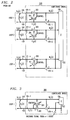
- FIG. 5 shows an arrangement wherein adaptive echo canceller 201, identical in structure to that shown in FIG. 2 and, therefore, designated by the same reference numerals, is disposed in lieu of the fixed echo canceller 401.
- Echo canceller 201 is adaptive using well-known training sequence techniques wherein each sequence includes a plurality of a priori known signals. Each sequence is transmitted at predetermined times, e.g., at system start-up and at predetermined times thereafter. At each such time, only the training sequence is transmitted.
- training sequence generator 501 provides a training sequence whose z transform is designated as P(z) at each predetermined time.
- Adder 502 provides a control signal equal to the algebraic difference between P(z) and T(z). This control signal varies the coefficients of echo canceller 201 in well-known fashion and thereby varies the amount of echo cancellation provided by canceller 201.
- Signal combiner 503 provides the same function as signal combiner 403 in FIG. 4 and, in addition, receives the training sequence at each predetermined time via input link 504. Except for the above-described substitution of an adaptive echo canceller for a fixed echo canceller, the embodiment of FIG. 5 operates in the same manner as that described for FIG. 4.
- variable attenuators 601-1 through 601-n are respectively disposed in the incoming paths 102 in each of the n communications links 101-1 through 101-n. Otherwise, the arrangement of FIG. 6 is identical to that shown in FIG. 5.
- Each of these attenuators provides the same amount of attenuation during the transmission of a training sequence. Initially, each attenuator provides some predetermined amount of attenuation. This predetermined amount of attenuation is then gradually decreased during the training sequence interval.
- each attenuator during the training sequence interval is controlled via a common control signal.
- switches 701-1 through 701-n can be used in lieu of attenuators 601-1 through 601-n.
- the remaining circuitry in FIG. 7 is identical to that shown in FIG. 5. In the arrangement of FIG. 7, all of these switches, except for one, are open at the commencement of a training sequence interval. During the training sequence interval, the n-1 open switches are successively closed. Operation of each switch is governed via a control signal.
- the echo canceller is noncontinuously adapted only during training sequence transmission.
- the amount of echo cancellation required may change due to a variety of factors, such as the addition or deletion in the number of users in the conference call and/or variations in the electrical characteristics of the communications paths being conferenced together. Therefore, it is often desirable to provide continuous adaptation of the echo canceller. This capability can be accomplished with the arrangement shown in FIG. 8.
- each of the coefficients of the echo canceller 401 is updated with every output T(z) sample provided by signal combiner 403.
- the coefficients are, therefore, updated at the rate of the incoming signal samples on the incoming paths 102 associated with each of the N users. As one or more of these coefficients change, so does the z transform, H(z), of the echo canceller.
- echo canceller 401 has an ordered sequence of M coefficients, where M is a predetermined integer. Any one of these coefficients will be designated as h q m , where m is an index representative of the position of the coefficient in the sequence and 1 ⁇ m ⁇ M, and q is an index representative of the designated coefficient at any of the sampling intervals associated with the successive incoming signal samples on any of the N incoming paths 102.
- any echo canceller coefficient h m at sampling time q+1, i.e., can be expressed as where h q m is the value of this coefficient in the immediately preceding sampling time, A is a predetermined scalar commonly referred to as the tap update rate constant, and is the maximum one of the incoming signal at sampling time q-m on any of the incoming paths 102 for each of the n users and is the signal supplied at the qth sampling time to the user associated with M max at sampling time q-m.
- equation (16) is to uncorrelate the terms
- this embodiment will eliminate the coupling of an echo of the speaking conferee back to that conferee and will provide each of the non-speaking conferees with an echo-free signal sample of the speaking conferee.
- Circuit 801 includes selector 802 which receives the signal samples on each of the incoming paths 102 and selects the maximum signal sample value every sampling interval and determines the index i of the user associated with each selected maximum signal sample value.
- the selected maximum signal sample values and associated indices i are successively coupled to shift registers 803 and 804, respectively.
- shift registers 803 and 804 Each of these shift register contain M cells and the successive inputs to each of these registers are shifted through the register cells at the incoming signal sample rate.
- Buses 805 and 806 respectively provide the stored values in registers 803 and 804 to processor 807 and selector 808 each sampling interval.
- Processor 807 determines each of the coefficients in accordance with equation (16).
- This selector receives each of the signals on paths 103 and selects each of the indices i. For each of the indices i, selector 808 selects the signal on path 103 corresponding to this index and provides each selected signal to the processor.
- the coefficient values determined by processor 807 are stored in coefficient memory 809 and thence coupled back to the processor for use in accordance with equation (16).
- the processor could provide the M updated coefficients every sampling interval or could successively provide a different coefficient update every sampling interval.
- the former operation requires a single processor to operate at M times the signal sample rate while the latter requires processor operation at the signal sample rate but requires M sampling intervals to update the echo canceller coefficients. This latter mode of operation may be suitable in applications where the echo cancellation required changes slowly relative to the incoming signal sample rate.
- the attenuators or switches as shown in FIGS. 6 and 7 could be combined with the circuitry shown in FIG. 8.
- the devices can be implemented using one or more appropriately programmed, general-purpose processors or special-purpose integrated circuits or digital processors or an analog or hybrid counterpart of any of these devices.
- signals samples of the users are digitally processed, the present invention could be implemented without signal sampling through the use of a conference bridge circuit having analog components.
- the signal samples in the disclosed embodiments are all formed at a common sampling rate, well-known digital techniques can be utilized to permit the utilization of signal samples formed at different sampling rates.
Abstract
Description
- The present invention relates to communications systems and, more particularly, to such systems having circuitry for reducing echoes in a conference communications originating from three or more information signal sources.
- Conferencing is the capability in a communications system of coupling information signals among three or more system subscribers. The information signals are typically voice signals but, with the advent of multimedia communications capabilities, can also be non-voice signals, i.e., data, video, facsimile and the like.
- Echoes are a major problem in conferencing circuits. When a large number of circuits are interconnected in a conference call, the cumulative effect of many echo paths severely degrades voice quality and circuit instability can render the communications unintelligible. Prior art solutions to the problem of echoes have either introduced attenuation into each of the circuits or have provided echo cancellation via circuitry disposed in each of the circuits interconnected in the conference call. The former technique limits the maximum number of system users or "conferees" in a conference call while the latter solution to the echo problem is expensive to implement in communications systems. It would, therefore, be desirable if a readily implementable, low-cost echo reduction technique could be provided for conferencing circuitry.
- In accordance with the present invention, echoes in a conference call are reduced through the use of an echo canceller which is connected to a signal combiner in a conference bridging circuit. In the disclosed embodiments, the combiner receives the information signals to be conferenced along with an echo compensation signal and provides an output representative of a sum of these signals. The echo canceller receives the signal combiner output and provides the echo compensation signal. Advantageously, the echo canceller can provide fixed or adaptive echo compensation and, in the latter case, the adaptation can be provided in response to the information signals or to training sequences.
-
- FIG. 1 is a block-schematic diagram of one prior art arrangement for reducing echoes in a conference call;
- FIG. 2 is a block-schematic diagram of another prior art arrangement for cancelling echoes in a conference call;
- FIG. 3 is a block-schematic diagram of a conference bridge which illustrates the principles of the present invention;
- FIG. 4 is a block-schematic diagram of a first embodiment of the present invention utilizing a fixed echo canceller;
- FIG. 5 is a block-schematic diagram of a second embodiment of the present invention utilizing an adaptive echo canceller;
- FIGS. 6 and 7 are variations of the embodiment shown in FIG. 5; and
- FIG. 8 is a third embodiment of the present invention utilizing an adaptive echo canceller.
- The present invention will be described relative to the conferencing of voice signals, it being understood, of course, that the present invention is also applicable to the conferencing of non-voice signals. A basic representation of a
conference bridge 100 is shown in FIG. 1. Bridge 100 provides illustrative voice conferencing communications capability for n users, where n is a predetermined integer ≧3. This bridge may be disposed in a variety of communication systems including private branch exchanges (PBXs), key telephone systems or the public telephone network. Each of the n users is connected to the conference bridge via one of n communications links 101-1 through 101-n. Each of these links includes anincoming path 102 and anoutgoing path 103. Combiner 104 in the bridge unit is connected to each of the nincoming paths 102 and provides an output signal, T(z), to each of the noutgoing paths 103. It shall be assumed that no loss is introduced by the conference bridge. The output signal T(z) is, therefore, equal to the sum of the signals on all nincoming paths 102. A signal subtractor, designated as 105-1 through 105-n, is disposed in eachoutgoing path 103. Each subtractor subtracts any signal coupled on the incoming path of a link from the composite signal coupled to the outgoing path of that link. As a result, each of the n users hears the speech of all of the other n-1 users. - Each of the n links is typically four wires, i.e., it includes a first pair of wires for
incoming path 102 and a second pair of wires foroutgoing path 103. Each of the n links shown in FIG. 1 and those which follow can be connected to one or more different communication links (not shown) including those referred to as two wire links, optical fiber links and wireless links. - We shall now assume that the signals coupled to the paths are samples of linearly encoded speech and that all processing is digital at the same sampling rate. We can therefore represent all signals and filters by their z transforms. The signal delivered to the ith port is designated as Ei(z). The signal coupled on the incoming path of this user is designated as Si(z) but, due to echo coupling, Di(z), the signal received by
bridge unit 100 for this user can be represented by Mi(z) where

The output signal provided bycombiner 104 can be represented by
and the ith output coupled back to the ith user is then formed by subtracting this user's input signal from output signal T(z) to yield
Manipulating these equations produces the result
where
and
The last term in equation (6) represents an unwanted "sidetone" or echo of a user's own speech caused by echo coupling of that speech through all of the other user's signal paths while the first term in equation (6) is the echo-distorted contribution due to all other users. Stability is primarily determined by the location of zeroes in the quantity Q(z), and the expression for this quantity set forth in equation (5) clearly reveals the effect of echo accumulation. - The problem of echo accumulation can be appreciated by considering the case of n users, each with an identical signal echo D(z) = az-p, where |a| <1 and p is equal to an integer number of sampling period delays. Then

so that the system becomes unstable if
This relationship of the allowed value of a to the number of users for system stability demonstrates the sensitivity of a conference bridge to the number of users, even when the amount of echo coupling between the paths of each link is moderate. Equation (6) reduces to
Equation (8) clearly reveals that even when the system is stable, increasing the number of users in a conference call increases the distortion of the desired signal sum and also the amount of sidetone. - One prior art technique to reduce the problem of echoes is to provide an attenuator in each of the communications paths to reduce the echo coupling by reducing the amplitude of the signal provided to each user. This solution is shown in FIG. 1 by the addition of
attenuators 106. The problem with this approach is that it effectively limits the number of users in any conference call. In practical applications this number is approximately 6. - Another approach to reducing echoes is to provide an echo canceller for each user. FIG. 2 shows this approach by the addition of an
echo canceller 201 and asignal summer 202 to each of the communications links. Each echo canceller is connected between an associatedpath 103 and associatedsummer 202 and adapts using the signal Mi(z) to provide a signal to the associated summer which effectively cancels the echo coupled from the associatedpath 103 and forming part of the positive summer signal input. The z transform of the echo canceller for the ith user, where 1 ≦ i ≦ n, is designated as Hi(z). Referring to FIG. 2, it can be said thatecho canceller 201 effectively cancels the echo propagating from left to right onpath 102. As a result, after convergence of each echo canceller,

and
as desired. While the technique shown in FIG. 2 substantially eliminates the problem of echoes, an echo canceller is required for each user. Since this device is rather complex and expensive, the implementation of conferencing capability for a large number of users oftentimes exceeds system objectives. - It has been recognized that it is possible to reconfigure the arrangement of FIG. 2 so that each echo canceller cancels the echo propagating from right to left on an associated
path 103. This reconfiguration for one of the n conferenced parties, designated as user i, is shown in FIG. 3. In the arrangement of FIG. 3, each user's echo canceller cancels the echo present in the output signal T provided bysignal combiner 104. This arrangement, however, suffers from the same shortcoming of FIG. 2. In addition, the echo present in output signal T(z) is a composite echo of echo coupling from all users' paths and changes as a user is added or dropped from a conference call. As a result of the composite nature of the echo to be cancelled in FIG. 3, the echo is much larger and the required echo canceller is a more complex structure. Moreover, since this composite echo changes as a user is added or dropped from a conference call, each echo canceller must be readapted each time either event occurs. However, the echo to be cancelled at each port includes the composite of all echoes due to all other user paths. Therefore, particularly for a large number of users, all per-user echo cancellers will adapt to similar transfer functions, differing only in that each transfer function does not include the echo coupled between its associated incoming and outgoing paths. If we ignore this difference, all echo cancellers could be replaced by a single echo canceller. This is the broad notion underlying the present invention and an arrangement incorporating this notion is shown in FIG. 4. - Referring to FIG. 4,
nonadaptive echo canceller 401, having z transform H(z), is supplied with the combiner output signal T(z) as an input and supplies its output to an additionalcombiner input path 402. This echo canceller provides a predetermined fixed amount of echo cancellation.Signal combiner 403 utilizes this fixed amount of echo cancellation by subtracting the signal oncombiner input path 402 from the sum of the signals coupled on the nincoming paths 102. As will be shown, the use of the term echo "canceller" for such a structure in the arrangement of FIG. 4 is really a misnomer as theecho canceller 401 will not cancel all echoes but will substantially reduce them and, as a result, more precisely serves as an echo "reducer". Based on the previously presented equations, it can be shown that
If we could set
then
and
Comparing equations (14) and (6), it can be seen that the distortion and the sidetone no longer grow with the number of users. Nor is there any stability problem when the individual echo functions are each stable. To examine the residual echo effects, we can again look at the case of all echo coupling being represented by D(z) = az-p where |a| <1 and p is equal to an integer number of sampling period delays. Then
Unlike equation (8) there is no growth in any of the distorting factors as the number of users grow. The conferencing arrangement will also be stable even when

- While the arrangement of FIG. 4 may provide satisfactory echo reduction in certain conferencing applications, it is often times preferable to utilize an adaptive echo cancellation device which tracks variations in the amount of echo cancellation required. FIG. 5 shows an arrangement wherein
adaptive echo canceller 201, identical in structure to that shown in FIG. 2 and, therefore, designated by the same reference numerals, is disposed in lieu of the fixedecho canceller 401.Echo canceller 201 is adaptive using well-known training sequence techniques wherein each sequence includes a plurality of a priori known signals. Each sequence is transmitted at predetermined times, e.g., at system start-up and at predetermined times thereafter. At each such time, only the training sequence is transmitted. Accordingly, these time intervals must be "reserved in advance" so as to assure the absence of signals transmitted by any of the n users. As shown in FIG. 5,training sequence generator 501 provides a training sequence whose z transform is designated as P(z) at each predetermined time.Adder 502 provides a control signal equal to the algebraic difference between P(z) and T(z). This control signal varies the coefficients ofecho canceller 201 in well-known fashion and thereby varies the amount of echo cancellation provided bycanceller 201.Signal combiner 503 provides the same function assignal combiner 403 in FIG. 4 and, in addition, receives the training sequence at each predetermined time viainput link 504. Except for the above-described substitution of an adaptive echo canceller for a fixed echo canceller, the embodiment of FIG. 5 operates in the same manner as that described for FIG. 4. - In certain applications, there may be instability in the conference circuit which precludes proper adaptation of
echo canceller 201 in FIG. 5. To overcome this problem, the arrangements shown in FIGS. 6 and 7 may be utilized. In FIG. 6 which is identical, variable attenuators 601-1 through 601-n are respectively disposed in theincoming paths 102 in each of the n communications links 101-1 through 101-n. Otherwise, the arrangement of FIG. 6 is identical to that shown in FIG. 5. Each of these attenuators provides the same amount of attenuation during the transmission of a training sequence. Initially, each attenuator provides some predetermined amount of attenuation. This predetermined amount of attenuation is then gradually decreased during the training sequence interval. The amount of attenuation provided by each attenuator during the training sequence interval is controlled via a common control signal. Alternatively, as shown in FIG. 7, switches 701-1 through 701-n can be used in lieu of attenuators 601-1 through 601-n. The remaining circuitry in FIG. 7 is identical to that shown in FIG. 5. In the arrangement of FIG. 7, all of these switches, except for one, are open at the commencement of a training sequence interval. During the training sequence interval, the n-1 open switches are successively closed. Operation of each switch is governed via a control signal. - With any of the arrangements shown in FIGS. 5-7, the echo canceller is noncontinuously adapted only during training sequence transmission. As a result, in the time periods between training sequence intervals, the amount of echo cancellation required may change due to a variety of factors, such as the addition or deletion in the number of users in the conference call and/or variations in the electrical characteristics of the communications paths being conferenced together. Therefore, it is often desirable to provide continuous adaptation of the echo canceller. This capability can be accomplished with the arrangement shown in FIG. 8.
- In FIG. 8, each of the coefficients of the
echo canceller 401 is updated with every output T(z) sample provided bysignal combiner 403. The coefficients are, therefore, updated at the rate of the incoming signal samples on theincoming paths 102 associated with each of the N users. As one or more of these coefficients change, so does the z transform, H(z), of the echo canceller. - It is assumed that
echo canceller 401 has an ordered sequence of M coefficients, where M is a predetermined integer. Any one of these coefficients will be designated as h
incoming paths 102. Pursuant to this embodiment of the invention, any echo canceller coefficient hm, at sampling time q+1, i.e.,
can be expressed as
where h

is the maximum one of the incoming signal at sampling time q-m on any of theincoming paths 102 for each of the n users and
is the signal supplied at the qth sampling time to the user associated with Mmax at sampling time q-m. It can be seen that the effect of equation (16) is to uncorrelate the terms
As a result, if at every sampling time there is only one conferee speaking, then this embodiment will eliminate the coupling of an echo of the speaking conferee back to that conferee and will provide each of the non-speaking conferees with an echo-free signal sample of the speaking conferee. - As shown in FIG. 8, the m coefficients of
echo canceller 201 inconference bridge 800 are updated via coefficients supplied bycoefficient updating circuit 801.Circuit 801 includesselector 802 which receives the signal samples on each of theincoming paths 102 and selects the maximum signal sample value every sampling interval and determines the index i of the user associated with each selected maximum signal sample value. The selected maximum signal sample values and associated indices i are successively coupled to shiftregisters Buses registers processor 807 andselector 808 each sampling interval.Processor 807 determines each of the coefficients in accordance with equation (16). The term
i.e., the signal returned onpath 103 in the any qth sampling interval for the user associated with the maximum selected signal sample value in m sampling intervals prior to the qth sampling interval, is provided viaselector 808. This selector receives each of the signals onpaths 103 and selects each of the indices i. For each of the indices i,selector 808 selects the signal onpath 103 corresponding to this index and provides each selected signal to the processor. The coefficient values determined byprocessor 807 are stored incoefficient memory 809 and thence coupled back to the processor for use in accordance with equation (16). It should be noted that the processor could provide the M updated coefficients every sampling interval or could successively provide a different coefficient update every sampling interval. The former operation requires a single processor to operate at M times the signal sample rate while the latter requires processor operation at the signal sample rate but requires M sampling intervals to update the echo canceller coefficients. This latter mode of operation may be suitable in applications where the echo cancellation required changes slowly relative to the incoming signal sample rate. - It should, of course, be noted that while the present invention has been described in terms of an illustrative embodiment, other arrangements will be apparent to those of ordinary skill in the art. First, for example, if stability is a problem in the embodiment shown in FIG. 8, the attenuators or switches as shown in FIGS. 6 and 7 could be combined with the circuitry shown in FIG. 8. Second, while the disclosed embodiments utilize discrete devices, the devices can be implemented using one or more appropriately programmed, general-purpose processors or special-purpose integrated circuits or digital processors or an analog or hybrid counterpart of any of these devices. Third, while in the disclosed embodiments, signals samples of the users are digitally processed, the present invention could be implemented without signal sampling through the use of a conference bridge circuit having analog components. Finally, while the signal samples in the disclosed embodiments are all formed at a common sampling rate, well-known digital techniques can be utilized to permit the utilization of signal samples formed at different sampling rates.
Claims (12)
- Apparatus for providing conferencing communications comprising
means for summing signals received from at least three information signal sources and providing a signal sum; and
an echo canceller responsive to said signal sum and an input to said summing means. - The apparatus of claim 1 further including means for providing a signal back to each of said plurality of signal sources, the signal returned to each source being equal to said signal sum minus the signal received from that source.
- The apparatus of claim 1 further including variable attenuators, each attenuator attenuating the signal coupled between a different one of the information signal sources and said summing means.
- The apparatus of claim 1 further including switch means disposed between each of the information signal sources and said summing means.
- The apparatus of claim 1 wherein said echo canceller provides a fixed amount of echo cancellation.
- The apparatus of claim 1 wherein said echo canceller is adaptive and provides a variable amount of echo cancellation.
- The apparatus of claim 6 farther including a training sequence generator and wherein said echo canceller has coefficients whose respective values are varied in response to a training sequence comprising a plurality of a priori known values supplied by said training sequence generator.
- The apparatus of claim 6 wherein said echo canceller has a plurality of coefficients whose values are varied at predetermined times and which remain fixed at other times during which signals from said information signal sources are coupled to said summing means.
- The apparatus of claim 6 wherein said echo canceller has a plurality of coefficients whose values are varied in response to processing of said signals from said plurality of information signal sources.
- The apparatus of claim 9 further including means for varying the values of said coefficients as a function of the maximum one of the signals received from said plurality of signal sources at each of a plurality of times.
- The apparatus of claim 10 wherein said function is also a function of a signal returned to the signal source supplying the maximum one of the signals received at each of said plurality of received times.
- A method of reducing echoes in conferencing communications comprising the steps of
forming an output signal representative of a sum of the signals received from at least three information signal sources minus an echo compensation signal; and
coupling said output signal to an echo canceller to form said echo compensation signal.
Applications Claiming Priority (2)
| Application Number | Priority Date | Filing Date | Title |
|---|---|---|---|
| US99906392A | 1992-12-31 | 1992-12-31 | |
| US999063 | 1992-12-31 |
Publications (2)
| Publication Number | Publication Date |
|---|---|
| EP0605960A1 true EP0605960A1 (en) | 1994-07-13 |
| EP0605960B1 EP0605960B1 (en) | 1999-06-16 |
Family
ID=25545852
Family Applications (1)
| Application Number | Title | Priority Date | Filing Date |
|---|---|---|---|
| EP93309758A Expired - Lifetime EP0605960B1 (en) | 1992-12-31 | 1993-12-06 | A technique for reducing echoes in conference communications |
Country Status (5)
| Country | Link |
|---|---|
| US (1) | US5363441A (en) |
| EP (1) | EP0605960B1 (en) |
| JP (1) | JPH06244760A (en) |
| CA (1) | CA2102857C (en) |
| DE (1) | DE69325357T2 (en) |
Cited By (3)
| Publication number | Priority date | Publication date | Assignee | Title |
|---|---|---|---|---|
| WO1997004577A1 (en) * | 1995-07-17 | 1997-02-06 | Hong Kong Telecommunications Limited | Loudspeaking telephone systems |
| EP2226995A1 (en) * | 2008-02-04 | 2010-09-08 | NEC Corporation | Voice mixing device and method, and multipoint conference server |
| EP2239931A1 (en) * | 2008-02-04 | 2010-10-13 | NEC Corporation | Voice mixing device and method, and multipoint conference server |
Families Citing this family (12)
| Publication number | Priority date | Publication date | Assignee | Title |
|---|---|---|---|---|
| US6594688B2 (en) | 1993-10-01 | 2003-07-15 | Collaboration Properties, Inc. | Dedicated echo canceler for a workstation |
| US5689641A (en) * | 1993-10-01 | 1997-11-18 | Vicor, Inc. | Multimedia collaboration system arrangement for routing compressed AV signal through a participant site without decompressing the AV signal |
| US5666407A (en) * | 1995-12-05 | 1997-09-09 | Ncr Corporation | Software-based bridging system for full duplex audio telephone conferencing |
| US5907497A (en) * | 1995-12-28 | 1999-05-25 | Lucent Technologies Inc. | Update block for an adaptive equalizer filter configuration |
| US5754631A (en) * | 1996-09-30 | 1998-05-19 | Intervoice Limited Partnership | Voice response unit having robot conference capability on ports |
| US5805696A (en) * | 1996-12-09 | 1998-09-08 | Lucent Technologies, Inc. | Echo canceller adaptation technique |
| US7245710B1 (en) * | 1998-04-08 | 2007-07-17 | British Telecommunications Public Limited Company | Teleconferencing system |
| DE19850271A1 (en) * | 1998-10-31 | 2000-05-04 | Alcatel Sa | Method for determining an echo coupling factor and the echo delay in a bidirectional telecommunication system |
| FI112016B (en) * | 2001-12-20 | 2003-10-15 | Nokia Corp | Conference Call Events |
| WO2008133686A1 (en) * | 2007-04-27 | 2008-11-06 | Hewlett-Packard Development Company, L.P. | System and method of calibrating an echo canceller using preemptive tone sequencing |
| US8724798B2 (en) | 2009-11-20 | 2014-05-13 | Adobe Systems Incorporated | System and method for acoustic echo cancellation using spectral decomposition |
| US20140334825A1 (en) * | 2011-12-06 | 2014-11-13 | Koninklijke Philips N.V. | Protocols for coded light communications |
Citations (5)
| Publication number | Priority date | Publication date | Assignee | Title |
|---|---|---|---|---|
| DE3306995A1 (en) * | 1983-02-28 | 1984-08-30 | Siemens AG, 1000 Berlin und 8000 München | Circuit arrangement for telecommunications switching systems, in particular PCM telephone switching systems, with conference circuits |
| JPS60226262A (en) * | 1984-04-25 | 1985-11-11 | Fujitsu Ltd | Control system for conference telephone call |
| DE3427303A1 (en) * | 1984-07-20 | 1986-01-30 | Siemens AG, 1000 Berlin und 8000 München | CONFERENCE CIRCUIT FOR DIGITAL COMMUNICATION SYSTEMS |
| JPS6429154A (en) * | 1987-07-24 | 1989-01-31 | Nippon Telegraph & Telephone | Voice conference equipment |
| US4901308A (en) * | 1986-12-08 | 1990-02-13 | Dsc Communications Corporation | Digital bridge for a time slot interchange digital switched matrix |
Family Cites Families (5)
| Publication number | Priority date | Publication date | Assignee | Title |
|---|---|---|---|---|
| US4456789A (en) * | 1978-03-07 | 1984-06-26 | The Post Office | Audio teleconferencing |
| US4600815A (en) * | 1982-07-30 | 1986-07-15 | Communications Satellite Corporation | Automatic gain control for echo cancellers and similar adaptive systems |
| JPH01319360A (en) * | 1988-06-20 | 1989-12-25 | Nec Corp | Voice conference equipment |
| US4991166A (en) * | 1988-10-28 | 1991-02-05 | Shure Brothers Incorporated | Echo reduction circuit |
| JP2785336B2 (en) * | 1989-06-13 | 1998-08-13 | 日本電気株式会社 | Training method of acoustic echo canceller |
-
1993
- 1993-11-10 CA CA002102857A patent/CA2102857C/en not_active Expired - Fee Related
- 1993-12-06 DE DE69325357T patent/DE69325357T2/en not_active Expired - Fee Related
- 1993-12-06 EP EP93309758A patent/EP0605960B1/en not_active Expired - Lifetime
- 1993-12-28 JP JP5349150A patent/JPH06244760A/en active Pending
-
1994
- 1994-02-14 US US08/195,595 patent/US5363441A/en not_active Expired - Lifetime
Patent Citations (5)
| Publication number | Priority date | Publication date | Assignee | Title |
|---|---|---|---|---|
| DE3306995A1 (en) * | 1983-02-28 | 1984-08-30 | Siemens AG, 1000 Berlin und 8000 München | Circuit arrangement for telecommunications switching systems, in particular PCM telephone switching systems, with conference circuits |
| JPS60226262A (en) * | 1984-04-25 | 1985-11-11 | Fujitsu Ltd | Control system for conference telephone call |
| DE3427303A1 (en) * | 1984-07-20 | 1986-01-30 | Siemens AG, 1000 Berlin und 8000 München | CONFERENCE CIRCUIT FOR DIGITAL COMMUNICATION SYSTEMS |
| US4901308A (en) * | 1986-12-08 | 1990-02-13 | Dsc Communications Corporation | Digital bridge for a time slot interchange digital switched matrix |
| JPS6429154A (en) * | 1987-07-24 | 1989-01-31 | Nippon Telegraph & Telephone | Voice conference equipment |
Non-Patent Citations (3)
| Title |
|---|
| JENS NEDERGAARD ET AL: "AN ALL-DIGITAL AUDIOCONFERENCE SYSTEM", 1990 INTERNATIONAL ZURICH SEMINAR ON DIGITAL COMMUNICATIONS, 5 March 1990 (1990-03-05), ZURICH(CH), pages 163 - 172 * |
| PATENT ABSTRACTS OF JAPAN vol. 10, no. 82 (E - 392) 2 April 1986 (1986-04-02) * |
| PATENT ABSTRACTS OF JAPAN vol. 13, no. 218 (E - 761) 22 May 1989 (1989-05-22) * |
Cited By (9)
| Publication number | Priority date | Publication date | Assignee | Title |
|---|---|---|---|---|
| WO1997004577A1 (en) * | 1995-07-17 | 1997-02-06 | Hong Kong Telecommunications Limited | Loudspeaking telephone systems |
| GB2317535A (en) * | 1995-07-17 | 1998-03-25 | Hong Kong Telecommunications L | Loudspeaking telephone systems |
| GB2317535B (en) * | 1995-07-17 | 1999-10-13 | Hong Kong Telecommunications L | Loudspeaking telephone systems |
| EP2226995A1 (en) * | 2008-02-04 | 2010-09-08 | NEC Corporation | Voice mixing device and method, and multipoint conference server |
| EP2239931A1 (en) * | 2008-02-04 | 2010-10-13 | NEC Corporation | Voice mixing device and method, and multipoint conference server |
| EP2239931A4 (en) * | 2008-02-04 | 2012-01-11 | Nec Corp | Voice mixing device and method, and multipoint conference server |
| EP2226995A4 (en) * | 2008-02-04 | 2012-01-11 | Nec Corp | Voice mixing device and method, and multipoint conference server |
| US8489216B2 (en) | 2008-02-04 | 2013-07-16 | Nec Corporation | Sound mixing apparatus and method and multipoint conference server |
| US8509460B2 (en) | 2008-02-04 | 2013-08-13 | Nec Corporation | Sound mixing apparatus and method and multipoint conference server |
Also Published As
| Publication number | Publication date |
|---|---|
| DE69325357T2 (en) | 1999-12-16 |
| US5363441A (en) | 1994-11-08 |
| CA2102857A1 (en) | 1994-07-01 |
| EP0605960B1 (en) | 1999-06-16 |
| DE69325357D1 (en) | 1999-07-22 |
| JPH06244760A (en) | 1994-09-02 |
| CA2102857C (en) | 1998-06-23 |
Similar Documents
| Publication | Publication Date | Title |
|---|---|---|
| US5363441A (en) | Technique for reducing echoes in conference communications | |
| US5315585A (en) | Echo canceller using two residual echoes | |
| US5663955A (en) | Echo canceller system with shared coefficient memory | |
| US3499999A (en) | Closed loop adaptive echo canceller using generalized filter networks | |
| US3500000A (en) | Self-adaptive echo canceller | |
| AU680981B2 (en) | Method for determining the location of echo in an echo cancellar | |
| US5195132A (en) | Telephone network speech signal enhancement | |
| US4268727A (en) | Adaptive digital echo cancellation circuit | |
| EP1202469B1 (en) | Echo canceler and echo path estimating method | |
| US4587382A (en) | Echo canceller using end delay measurement | |
| US3647992A (en) | Adaptive echo canceller for nonlinear systems | |
| US5351291A (en) | Adaptive echo cancellation method and device for implementing said method | |
| JPS6171728A (en) | Digital echo canceller | |
| US4057696A (en) | Recursive-like adaptive echo canceller | |
| US4554417A (en) | Tandem adaptive echo canceler arrangement | |
| US6337907B1 (en) | Echo canceller employing dual-H architecture having improved coefficient transfer | |
| US3508017A (en) | Adaptive echo canceller with an output filter | |
| DE19714966C2 (en) | Device for reducing attenuation | |
| Wehrmann et al. | A noise-insensitive compromise gradient method for the adjustment of adaptive echo cancellers | |
| US5805696A (en) | Echo canceller adaptation technique | |
| CA2027236A1 (en) | Adaptive fir filter having restricted coefficient ranges | |
| US7027593B2 (en) | Apparatus and method for echo control | |
| JP3355594B2 (en) | Echo canceller device | |
| US5799078A (en) | Echo canceller | |
| CA1091833A (en) | Recursive-like adaptive echo canceller |
Legal Events
| Date | Code | Title | Description |
|---|---|---|---|
| PUAI | Public reference made under article 153(3) epc to a published international application that has entered the european phase |
Free format text: ORIGINAL CODE: 0009012 |
|
| AK | Designated contracting states |
Kind code of ref document: A1 Designated state(s): DE FR IT |
|
| 17P | Request for examination filed |
Effective date: 19941208 |
|
| 17Q | First examination report despatched |
Effective date: 19980114 |
|
| GRAG | Despatch of communication of intention to grant |
Free format text: ORIGINAL CODE: EPIDOS AGRA |
|
| GRAG | Despatch of communication of intention to grant |
Free format text: ORIGINAL CODE: EPIDOS AGRA |
|
| GRAH | Despatch of communication of intention to grant a patent |
Free format text: ORIGINAL CODE: EPIDOS IGRA |
|
| GRAH | Despatch of communication of intention to grant a patent |
Free format text: ORIGINAL CODE: EPIDOS IGRA |
|
| GRAA | (expected) grant |
Free format text: ORIGINAL CODE: 0009210 |
|
| AK | Designated contracting states |
Kind code of ref document: B1 Designated state(s): DE FR IT |
|
| REF | Corresponds to: |
Ref document number: 69325357 Country of ref document: DE Date of ref document: 19990722 |
|
| ET | Fr: translation filed | ||
| PLBE | No opposition filed within time limit |
Free format text: ORIGINAL CODE: 0009261 |
|
| STAA | Information on the status of an ep patent application or granted ep patent |
Free format text: STATUS: NO OPPOSITION FILED WITHIN TIME LIMIT |
|
| 26N | No opposition filed | ||
| PGFP | Annual fee paid to national office [announced via postgrant information from national office to epo] |
Ref country code: FR Payment date: 20081212 Year of fee payment: 16 |
|
| PGFP | Annual fee paid to national office [announced via postgrant information from national office to epo] |
Ref country code: DE Payment date: 20081205 Year of fee payment: 16 |
|
| PGFP | Annual fee paid to national office [announced via postgrant information from national office to epo] |
Ref country code: IT Payment date: 20081229 Year of fee payment: 16 |
|
| REG | Reference to a national code |
Ref country code: FR Ref legal event code: ST Effective date: 20100831 |
|
| PG25 | Lapsed in a contracting state [announced via postgrant information from national office to epo] |
Ref country code: FR Free format text: LAPSE BECAUSE OF NON-PAYMENT OF DUE FEES Effective date: 20091231 |
|
| PG25 | Lapsed in a contracting state [announced via postgrant information from national office to epo] |
Ref country code: DE Free format text: LAPSE BECAUSE OF NON-PAYMENT OF DUE FEES Effective date: 20100701 |
|
| PG25 | Lapsed in a contracting state [announced via postgrant information from national office to epo] |
Ref country code: IT Free format text: LAPSE BECAUSE OF NON-PAYMENT OF DUE FEES Effective date: 20091206 |