EP0605847A1 - Elektromagnetischewellereflexionsensor - Google Patents
Elektromagnetischewellereflexionsensor Download PDFInfo
- Publication number
- EP0605847A1 EP0605847A1 EP93120760A EP93120760A EP0605847A1 EP 0605847 A1 EP0605847 A1 EP 0605847A1 EP 93120760 A EP93120760 A EP 93120760A EP 93120760 A EP93120760 A EP 93120760A EP 0605847 A1 EP0605847 A1 EP 0605847A1
- Authority
- EP
- European Patent Office
- Prior art keywords
- frequency
- field
- wheel
- target
- reflectivity
- Prior art date
- Legal status (The legal status is an assumption and is not a legal conclusion. Google has not performed a legal analysis and makes no representation as to the accuracy of the status listed.)
- Withdrawn
Links
Images
Classifications
-
- G—PHYSICS
- G01—MEASURING; TESTING
- G01D—MEASURING NOT SPECIALLY ADAPTED FOR A SPECIFIC VARIABLE; ARRANGEMENTS FOR MEASURING TWO OR MORE VARIABLES NOT COVERED IN A SINGLE OTHER SUBCLASS; TARIFF METERING APPARATUS; MEASURING OR TESTING NOT OTHERWISE PROVIDED FOR
- G01D5/00—Mechanical means for transferring the output of a sensing member; Means for converting the output of a sensing member to another variable where the form or nature of the sensing member does not constrain the means for converting; Transducers not specially adapted for a specific variable
- G01D5/12—Mechanical means for transferring the output of a sensing member; Means for converting the output of a sensing member to another variable where the form or nature of the sensing member does not constrain the means for converting; Transducers not specially adapted for a specific variable using electric or magnetic means
- G01D5/244—Mechanical means for transferring the output of a sensing member; Means for converting the output of a sensing member to another variable where the form or nature of the sensing member does not constrain the means for converting; Transducers not specially adapted for a specific variable using electric or magnetic means influencing characteristics of pulses or pulse trains; generating pulses or pulse trains
- G01D5/245—Mechanical means for transferring the output of a sensing member; Means for converting the output of a sensing member to another variable where the form or nature of the sensing member does not constrain the means for converting; Transducers not specially adapted for a specific variable using electric or magnetic means influencing characteristics of pulses or pulse trains; generating pulses or pulse trains using a variable number of pulses in a train
- G01D5/2451—Incremental encoders
-
- G—PHYSICS
- G01—MEASURING; TESTING
- G01D—MEASURING NOT SPECIALLY ADAPTED FOR A SPECIFIC VARIABLE; ARRANGEMENTS FOR MEASURING TWO OR MORE VARIABLES NOT COVERED IN A SINGLE OTHER SUBCLASS; TARIFF METERING APPARATUS; MEASURING OR TESTING NOT OTHERWISE PROVIDED FOR
- G01D5/00—Mechanical means for transferring the output of a sensing member; Means for converting the output of a sensing member to another variable where the form or nature of the sensing member does not constrain the means for converting; Transducers not specially adapted for a specific variable
- G01D5/48—Mechanical means for transferring the output of a sensing member; Means for converting the output of a sensing member to another variable where the form or nature of the sensing member does not constrain the means for converting; Transducers not specially adapted for a specific variable using wave or particle radiation means
-
- G—PHYSICS
- G01—MEASURING; TESTING
- G01D—MEASURING NOT SPECIALLY ADAPTED FOR A SPECIFIC VARIABLE; ARRANGEMENTS FOR MEASURING TWO OR MORE VARIABLES NOT COVERED IN A SINGLE OTHER SUBCLASS; TARIFF METERING APPARATUS; MEASURING OR TESTING NOT OTHERWISE PROVIDED FOR
- G01D2205/00—Indexing scheme relating to details of means for transferring or converting the output of a sensing member
- G01D2205/70—Position sensors comprising a moving target with particular shapes, e.g. of soft magnetic targets
- G01D2205/77—Specific profiles
- G01D2205/777—Whorl-shaped profiles
Definitions
- This invention is generally directed to the field of encoders and particularly to the field of electromagnetic wave sensors operating on a principal of sensed reflectivity. These devices may be applied to construct incremental, multi-state, or absolute position encoders and also proximity and wheel position, or speed sensors.
- Encoders come in many forms, the one-state encoder also generally known as a proximity switch, the two-state encoder, or incremental encoder, also referred to as a quadrature encoder when implementing direction sensing, and the multi-state or absolute encoder.
- Technology for one and two-state encoders include killed oscillator eddy-current sensors, variable reluctance sensors, Hall-effect sensors, reflective optical sensors, metal detectors, and microwave sensors.
- the eddy-current sensors are limited to applications that rely on a very large change in field disturbance to kill an oscillator. These killed oscillator circuits require large changes in reactance. This means that the size of the detected target needs to be large, thus yielding a coarse resolution system.
- variable reluctance sensors are typically used to sense a toothed, or binarily arranged, metallic wheel for sensing rotary position, or speed. These sensors are very sensitive to the gap distance between the teeth on the wheel and the sensor both at installation and in field with road and suspension vibration and shock. Also, as the speed, or rotational velocity changes the voltage output from these sensors varies. For instance, in an automotive application, when sensing wheel speeds between 20 miles per hour and 55 miles per hour the sensor may output a periodic voltage ranging from 10 mv to 100 volts. This makes the interfacing electronics both difficult to design, and complex. Further, with automotive suppliers converting anti-skid braking systems to include traction control function, these sensors need to work at much lower speeds than 20 miles per hour. Building a variable reluctance sensory system for detecting speeds at less than 20 miles per hour is unreliable because the signal gets too small.
- Hall-effect sensors are also sensitive to the gap between the target and the sensor and have a limited temperature operating range. Also these sensors rely on a gross change in a polarity of a magnetic field. This means that the target is typically limited to a magnetic material. This makes the target both expensive, and due to the composition of the magnetic material, unreliable at high rotary speeds and high operating temperatures.
- Reflective optical sensors are generally fragile, are limited to a medium temperature range, have a medium resolution, and need relatively clean environment to operate reliably.
- Metal detectors that detect a shift in frequency, are used to detect large targets introduced into a radiating field based on a change in inductance attributable to permittivity, or permeability due to a permeable target intruding this field.
- This type of sensor technology is only suited to constructing very simple low resolution encoders because of the relatively large target needed to significantly shift the oscillator frequency.
- the Doppler shift sensors are normally used to measure the speed of a passing object. Although they may be adapted in a one or two-state encoder they are expensive and complex, thereby less reliable than other, simpler approaches.
- the other major type of microwave based sensors look for a major change in an oscillator's reactive field by introducing a reactive target within the field, thereby killing, or starting the oscillator. This scheme, like others described before is limited to sensing large changes in reactance. This means, for the case of a two-state encoder, the difference between the sensed object and the counterpart non-sensed object must be substantial. This means this prior art scheme is limited in its ability to construct medium and high resolution sensors.
- Technology for multi-state sensors include resolvers, and optical encoders.
- Resolvers are plagued by high cost, large physical size, must be directly coupled to the measured device, and they require very complex electrical interfaces to work.
- Optical encoders are limited in resolution, fragile, and have poor high temperature performance.
- An electromagnetic wave reflectivity sensor is constructed using an oscillator, preferably tuned within the microwave spectrum.
- the oscillator provides a radiating wave at a frequency influenced by a load impedance within a field.
- the load impedance within the field is influenced by a vector sum of the radiating wave and a reflected wave.
- the reflected wave has a magnitude and phase responsive to a reflection characteristic of a to be provided target.
- a frequency detection device preferably a frequency to voltage converter, with a level comparator, is coupled to the oscillator.
- the frequency detection device provides an output responsive to a change in the frequency of the oscillator, corresponding to a change the load impedance caused by a reflection of the radiating wave from the to be provided target located within the field.
- This sensor constructed with the appropriate target and frequency detection devices, can be used to construct either a one-state, two-state, or multi-state absolute or incremental encoder.
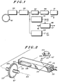
- FIG. 1 shows a system block diagram of the sensory system including provision for several embodiments.
- an automotive wheel position, or speed sensor is constructed.
- This sensor may be attached to a vehicular wheel component that rotates as the vehicle traverses.
- a toothed wheel 101 has alternately disposed marks and spaces along a continuous circumferential surface of the wheel.
- the marks have a first characteristic spectral reflectivity to a predetermined frequency, preferably in the microwave frequency range, and the spaces have a second characteristic spectral reflectivity to the predetermined frequency.
- This toothed wheel 101 may be constructed several ways, as detailed later.
- all embodiments of this wheel have at least a mark and a space having different reflectivity coefficients in the microwave frequency range.
- the microwave band is considered to extend from about 1 GHz to 40 GHz and covers the L-Band to the KA-Band. Of course, other frequency bands across the electromagnetic spectrum may be used with appropriately sized elements.
- An antenna means in this case a coupler-resonator 103 is located opposite the toothed wheel 101.
- a microwave, or KU-Band, oscillator 105 is coupled to the coupler-resonator 103.
- the combination of the KU-Band oscillator 105, and the coupler-resonator 103 provide a radiating wave that emanates at a frequency influenced by a load impedance within a field.
- the load impedance is influenced by a characteristic impedance of free space within the field.
- a shift in the frequency occurs responsive to a change in the load impedance corresponding to a vector bum of the radiating wave and a reflected wave.
- the reflected wave has a magnitude and phase responsive to a reflectivity of the radiating wave from either the space or the mark.
- a frequency shift detector comprised of a filter 107, a detector 109, and a current switch 111, provide a output 113 responsive to a shift in the predetermined frequency of the KU-Band oscillator 105 corresponding to the changing reflectivity of the toothed wheel 101 as the wheel 101 rotates exposing either a space or a mark to the field.
- the filter 107 is designed to pass the oscillator's 105 frequency when a mark is in the field and will not pass the oscillator's frequency when a space is in the field. As the target wheel rotates this results in a constant peak amplitude periodic wave at the output 113 of the current switch 111. This provides a substantial advantage over the variable reluctance type wheel speed sensor because the output's 113 voltage is no longer dependent on wheel speed.
- FIG. 2 is a component level drawing further detailing several key components used in the preferred embodiment.
- Element 103' is a waveguide that represents the physical embodiment of the coupler-resonator from FIG. 1.
- waveguide 103' is a waveguide that represents the physical embodiment of the coupler-resonator from FIG. 1.
- those skilled in the art will recognize other, equivalent, structures such as a strip line or other antenna structures to substitute for the waveguide 103'.
- Element 203 comprises the KU-Band oscillator 105, the filter 107, the detector 109, and the current switch 111 all from FIG. 1, in an electronic package.
- This component 203 is constructed using a Gallium Arsenide Monolithic Microwave Integrated Circuit, or GaAs MMIC, technology. In this case it's tuned to approximately 18 GHz. Other frequencies may be used depending on the target, and waveguide, or antenna 103', design. The application of this technology allows for a very small, cost efficient package. GaAs technology inherently operates at a higher temperature than conventional silicon devices, making it well suited for the extreme temperature range found in the automotive environment.
- a connector 219, and wires 209 are provided on the side of the waveguide 103' to supply power, ground and output connections to the corresponding pins 205, 207, and 113' on the MMIC 203.
- the MMIC 203 When the MMIC 203 is powered it emits energy through port 201 to port 217 at about 18 GHz. This energy is coupled along the interior of the waveguide 103' to an emissions port 229 where a field is created. This field is emitted in a complex geometric pattern dependent on the actual oscillator 105 frequency and the structure of the antenna 103'. For purposes of illustration a center line 221 is used to represent a portion of this field.
- the toothed wheel 101' comprises a wheel having a predetermined circumference, with a multiplicity of marks 225, in this case a metal material. These marks exhibit a first characteristic reflectivity. These marks 225, are located interdigitated with a corresponding multiplicity of spaces 227, located with a distinct difference in distance from the oscillator means, 203, 103' and exhibiting a substantially different second reflectivity.
- the load impedance that the oscillator 105 sees changes.
- the load impedance within the field is influenced by a vector sum of the radiating wave and the reflected wave.
- the reflected wave has a magnitude, or amplitude and phase responsive to a reflection characteristic of a to be provided target, in this case the toothed wheel 101'.
- the change in load impedance can be modeled using the following deterministic relationship:
- This approach offers a significant advantage over killed oscillator eddy current sensors, killed oscillator microwave proximity sensors, and variable reluctance based approaches because a very small change in reflectivity will produce a corresponding change in oscillator frequency. This allows construction of a very high resolution sensor. There are many approaches for detecting this change in frequency. This also makes the target design much easier. Additionally, this approach is substantially less sensitive to air gap tolerances, and the peak amplitude of the periodic voltage at output 113, is substantially independent of wheel speed. These advantages eliminate the low speed sensing problems of the variable reluctance sensors, allowing application to traction control systems that need to sense very low wheel speeds.
- multi-state encoders can be easily constructed using this reflectivity sensor.
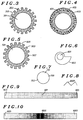
- FIG. 3 shows another view of the wheel 101' illustrated in FIG. 2.
- This wheel 301 has alternating spaces and marks each having a different reflectivity based on physical dimensions.
- the different reflectivities are caused by a distinct difference in distance between the mark 303 and the space 305, when compared to the distance between the wheel 301 and the oscillator means 103' 203.
- the teeth, or marks are constructed of metal, forged into a wheel.
- the intervening spaces are simply voids.
- the target surfaces have a 1/4 wavelength reflectivity relationship between the marks and spaces.
- the magnitude of the reflected signal depends on the distance from either the mark or space to the radiating source.
- the phase of the reflected signal also depends on the distance from either the mark or space to the radiating source.
- the difference in phase of the reflected signal is two times the electrical length of the mark or space height. This electrical length can be expressed in degrees using the following equation.
- a field of view of the antenna 103' The field of view is approximately equal to a size of the antenna 103' plus the region into which the antenna 103' radiates.
- the size of an aperture 229 is the size of importance.
- Antenna pattern calculations can be used to determine the angle of radiation coverage if the target 101' is in the far field of the antenna 103'.
- the far field of an antenna begins at a distance calculated as follows.
- FIG. 5 shows a wheel 501 having alternating spaces 505 and marks 503 and a special mark 507 having a reflectivity characteristic substantially different than the marks 503 and spaces 505.
- a mark, or tooth 507 is shown to have a different physical height than the mark, represented by 503.
- a different surface treatment on a tooth of the same height will work as well as long as the reflectivity at 18 GHz is substantially different than the spaces 505 or marks 503.
- a frequency to tri-state detection element consists of a frequency to voltage converter 115 and a voltage comparator 121.
- the frequency to voltage converter 115 output a voltage 117 that corresponds to the frequency of the KU-Band oscillator 105.
- the voltage comparator 121 compares this voltage 117 to a voltage threshold 119 and provides an output 127 activated when the voltage 117 exceeds the voltage threshold 119. This indicates that the special mark, or tooth 507 is intersecting the oscillator's field.
- This frequency to tri-state detection element 115, 121 is used to determine the substantially different mark 507.
- a three state encoder can be constructed using this frequency to tri-state detection element 115, 121 in tandem with elements 107, 109, and 111.
- those of ordinary skill in the art will recognize many other equivalent circuits and methods for achieving the detection of a particular shift in frequency.
- FIG. 6 shows a wheel 601 having a monotonically changing reflectivity characteristic.
- the wheel is shown having a monotonically receding circumferential surface.
- other non-monotonic surface geometries may be used to encode non-linear motion.
- a frequency to BCD, or Binary Coded Decimal converter 121 provides an output 119 having a multi-bit encoded digital word representing the reflectivity - thus the absolute rotary position of the target, in this case element 601 from FIG. 6.
- a binary, Gray code, or other encoding approach may be used.
- FIG. 7 shows a sphere 701 with a hemisphere coated with a monotonically changing reflectivity characteristic.
- Reference number 703 indicates a highly reflective area and reference number 705 indicates a far less reflective area.
- This target coupled with the apparatus in 103, 105, and 121 in FIG. 1 will allow transformation from a spherical movement to an absolute position.
- Target surfaces can exhibit different reflectivities to the KU-Band by distance differences, material differences and, as shown in FIG. 8 target surface treatment
- the surface geometry 801 has a highly reflective characteristic.
- FIG. 9 shows a surface that exhibits a monotonically changing reflectivity characteristic along a linear path.
- Reference number 905 indicates a highly reflective area and reference number 903 indicates a far less reflective area.
- this treated surface may be disposed on a wheel, or other continuous geometric surface to construct an absolute position encoder.
- FIG. 10 shows another surface that exhibits a monotonically changing reflectivity characteristic diverging from a center point along a bilateral linear path.
- Reference number 1005 indicates a highly reflective area and reference numbers 1001, and 1003 indicate substantially less reflective areas. This is an example of the flexibility of this approach. By designing the appropriate target, a linearization of any motion can be attained.
- frequencies in the microwave range are preferable for constructing automotive wheel sensors and other encoders because of the requirement to make these devices relatively physically small.
- many other encoding, and sensing devices can be constructed using other parts of the electromagnetic spectrum with correspondingly sized oscillator, frequency detection, and target means.
- targets other than solids may be used. These include liquids and gasses. For instance one may detect a change in humidity in a gas, the level of a liquid, or the thickness of ice on an airplane wing surface.
Landscapes
- Physics & Mathematics (AREA)
- General Physics & Mathematics (AREA)
- Optical Transform (AREA)
Applications Claiming Priority (2)
| Application Number | Priority Date | Filing Date | Title |
|---|---|---|---|
| US77193A | 1993-01-05 | 1993-01-05 | |
| US771 | 1993-01-05 |
Publications (1)
| Publication Number | Publication Date |
|---|---|
| EP0605847A1 true EP0605847A1 (de) | 1994-07-13 |
Family
ID=21692961
Family Applications (1)
| Application Number | Title | Priority Date | Filing Date |
|---|---|---|---|
| EP93120760A Withdrawn EP0605847A1 (de) | 1993-01-05 | 1993-12-23 | Elektromagnetischewellereflexionsensor |
Country Status (1)
| Country | Link |
|---|---|
| EP (1) | EP0605847A1 (de) |
Cited By (6)
| Publication number | Priority date | Publication date | Assignee | Title |
|---|---|---|---|---|
| WO1996041134A2 (en) * | 1995-06-07 | 1996-12-19 | Wolff Peter U | Method and apparatus for sensing proximity or position of an object using near-field or magnetic effects |
| WO1997040344A1 (en) * | 1996-04-23 | 1997-10-30 | R.D.P. Electronics Ltd. | Optical transducer, method and laser diode arrangement |
| GB2343517A (en) * | 1998-11-06 | 2000-05-10 | Laurence Ross Petrie | Displacement measurement |
| GB2364390A (en) * | 2000-07-03 | 2002-01-23 | Haj Yousef Yousri Mohammad Tah | Method and device for detecting movement of objects and/or fluid flow |
| WO2008119758A1 (de) * | 2007-03-29 | 2008-10-09 | Zf Friedrichshafen Ag | Drehwinkelsensor oder längensensor |
| WO2019197029A1 (de) * | 2018-04-12 | 2019-10-17 | Siemens Aktiengesellschaft | Mikrowellen-drehwinkelgeber |
Citations (2)
| Publication number | Priority date | Publication date | Assignee | Title |
|---|---|---|---|---|
| EP0199224A2 (de) * | 1985-04-12 | 1986-10-29 | Jodon Engineering Associates, Inc. | Verfahren und System zur Überwachung der Position eines hydraulischen Stellorganes unter Verwendung der Mikrowellenresonanz in Hohlräumen |
| EP0320442A2 (de) * | 1987-11-27 | 1989-06-14 | Karl-Heinz Schmall | Verwendung eines dielektrischen Mikrowellen-Resonators und Sensorschaltung |
-
1993
- 1993-12-23 EP EP93120760A patent/EP0605847A1/de not_active Withdrawn
Patent Citations (2)
| Publication number | Priority date | Publication date | Assignee | Title |
|---|---|---|---|---|
| EP0199224A2 (de) * | 1985-04-12 | 1986-10-29 | Jodon Engineering Associates, Inc. | Verfahren und System zur Überwachung der Position eines hydraulischen Stellorganes unter Verwendung der Mikrowellenresonanz in Hohlräumen |
| EP0320442A2 (de) * | 1987-11-27 | 1989-06-14 | Karl-Heinz Schmall | Verwendung eines dielektrischen Mikrowellen-Resonators und Sensorschaltung |
Cited By (10)
| Publication number | Priority date | Publication date | Assignee | Title |
|---|---|---|---|---|
| US5670886A (en) * | 1991-05-22 | 1997-09-23 | Wolf Controls Corporation | Method and apparatus for sensing proximity or position of an object using near-field effects |
| WO1996041134A2 (en) * | 1995-06-07 | 1996-12-19 | Wolff Peter U | Method and apparatus for sensing proximity or position of an object using near-field or magnetic effects |
| WO1996041134A3 (en) * | 1995-06-07 | 1997-02-06 | Peter U Wolff | Method and apparatus for sensing proximity or position of an object using near-field or magnetic effects |
| WO1997040344A1 (en) * | 1996-04-23 | 1997-10-30 | R.D.P. Electronics Ltd. | Optical transducer, method and laser diode arrangement |
| GB2343517A (en) * | 1998-11-06 | 2000-05-10 | Laurence Ross Petrie | Displacement measurement |
| GB2364390A (en) * | 2000-07-03 | 2002-01-23 | Haj Yousef Yousri Mohammad Tah | Method and device for detecting movement of objects and/or fluid flow |
| GB2364390B (en) * | 2000-07-03 | 2004-11-17 | Yousri Mohammad Tah Haj-Yousef | A method and device for detecting and monitoring concealed bodies and objects |
| WO2008119758A1 (de) * | 2007-03-29 | 2008-10-09 | Zf Friedrichshafen Ag | Drehwinkelsensor oder längensensor |
| US8581601B2 (en) | 2007-03-29 | 2013-11-12 | Zf Friedrichshafen Ag | Rotation angle sensor or length sensor |
| WO2019197029A1 (de) * | 2018-04-12 | 2019-10-17 | Siemens Aktiengesellschaft | Mikrowellen-drehwinkelgeber |
Similar Documents
| Publication | Publication Date | Title |
|---|---|---|
| CN1250883C (zh) | 液压活塞位置传感器 | |
| Pohl et al. | Wirelessly interrogable surface acoustic wave sensors for vehicular applications | |
| JP4026849B2 (ja) | 無線問合せ可能な表面波テクノロジーセンサ | |
| AU2001291619B2 (en) | Method for determining a rotational angle and/or an angle differential from phase signals | |
| US5521515A (en) | Frequency scanning capaciflector for capacitively determining the material properties | |
| US5736865A (en) | Capacitive rotary position encoder | |
| US20210288725A1 (en) | Methods and apparatuses for speed and/or position sensing | |
| US20020097180A1 (en) | Phase-based sensing system | |
| EP0605847A1 (de) | Elektromagnetischewellereflexionsensor | |
| US5471147A (en) | Apparatus and method for determining the linear position of a hydraulic cylinder | |
| WO2001055668A1 (en) | Absolute encoder | |
| MXPA01000833A (es) | Codificador de angulos. | |
| US7076998B2 (en) | Tire measuring device with a modulated backscatter transponder self-sufficient in terms of energy | |
| US5502380A (en) | Analog weighted binary absolute position encoder including an array of sense resistors each having material responsive to FWX and nonresponsive to flux | |
| Li et al. | An accurate low-cost capacitive absolute angular-position sensor with a full-circle range | |
| Pohl et al. | Wirelessly interrogable SAW-sensors for vehicular applications | |
| Montanari et al. | A novel analog multisensor design based on fuzzy logic: A magnetic encoder application | |
| US4887465A (en) | Transducers for hostile environments | |
| US7323864B2 (en) | Absolute angular position sensor on 360 of a rotating element | |
| US6969998B2 (en) | Measurement of angle rotation using microstrip resonators (2.4ghz,2 degree) | |
| WO2020046209A1 (en) | Optical position encoder | |
| Dong et al. | A multi-resolution passive SAW chemical sensor | |
| EP0618373B1 (de) | Positionsanzeiger | |
| WO2023033897A1 (en) | Linear inductive torque sensor | |
| Wolffenbuttel et al. | An integrable capacitive angular displacement sensor with improved linearity |
Legal Events
| Date | Code | Title | Description |
|---|---|---|---|
| PUAI | Public reference made under article 153(3) epc to a published international application that has entered the european phase |
Free format text: ORIGINAL CODE: 0009012 |
|
| 17P | Request for examination filed |
Effective date: 19931223 |
|
| AK | Designated contracting states |
Kind code of ref document: A1 Designated state(s): DE FR GB IT |
|
| STAA | Information on the status of an ep patent application or granted ep patent |
Free format text: STATUS: THE APPLICATION IS DEEMED TO BE WITHDRAWN |
|
| 18D | Application deemed to be withdrawn |
Effective date: 19950114 |