EP0605232B1 - Image projecting apparatus - Google Patents
Image projecting apparatus Download PDFInfo
- Publication number
- EP0605232B1 EP0605232B1 EP93310544A EP93310544A EP0605232B1 EP 0605232 B1 EP0605232 B1 EP 0605232B1 EP 93310544 A EP93310544 A EP 93310544A EP 93310544 A EP93310544 A EP 93310544A EP 0605232 B1 EP0605232 B1 EP 0605232B1
- Authority
- EP
- European Patent Office
- Prior art keywords
- image
- projection lens
- lens
- center axis
- light
- Prior art date
- Legal status (The legal status is an assumption and is not a legal conclusion. Google has not performed a legal analysis and makes no representation as to the accuracy of the status listed.)
- Expired - Lifetime
Links
Images


Classifications
-
- H—ELECTRICITY
- H04—ELECTRIC COMMUNICATION TECHNIQUE
- H04N—PICTORIAL COMMUNICATION, e.g. TELEVISION
- H04N5/00—Details of television systems
- H04N5/74—Projection arrangements for image reproduction, e.g. using eidophor
-
- H—ELECTRICITY
- H04—ELECTRIC COMMUNICATION TECHNIQUE
- H04N—PICTORIAL COMMUNICATION, e.g. TELEVISION
- H04N5/00—Details of television systems
- H04N5/74—Projection arrangements for image reproduction, e.g. using eidophor
- H04N5/7416—Projection arrangements for image reproduction, e.g. using eidophor involving the use of a spatial light modulator, e.g. a light valve, controlled by a video signal
- H04N5/7441—Projection arrangements for image reproduction, e.g. using eidophor involving the use of a spatial light modulator, e.g. a light valve, controlled by a video signal the modulator being an array of liquid crystal cells
-
- G—PHYSICS
- G02—OPTICS
- G02F—OPTICAL DEVICES OR ARRANGEMENTS FOR THE CONTROL OF LIGHT BY MODIFICATION OF THE OPTICAL PROPERTIES OF THE MEDIA OF THE ELEMENTS INVOLVED THEREIN; NON-LINEAR OPTICS; FREQUENCY-CHANGING OF LIGHT; OPTICAL LOGIC ELEMENTS; OPTICAL ANALOGUE/DIGITAL CONVERTERS
- G02F1/00—Devices or arrangements for the control of the intensity, colour, phase, polarisation or direction of light arriving from an independent light source, e.g. switching, gating or modulating; Non-linear optics
- G02F1/01—Devices or arrangements for the control of the intensity, colour, phase, polarisation or direction of light arriving from an independent light source, e.g. switching, gating or modulating; Non-linear optics for the control of the intensity, phase, polarisation or colour
- G02F1/13—Devices or arrangements for the control of the intensity, colour, phase, polarisation or direction of light arriving from an independent light source, e.g. switching, gating or modulating; Non-linear optics for the control of the intensity, phase, polarisation or colour based on liquid crystals, e.g. single liquid crystal display cells
- G02F1/133—Constructional arrangements; Operation of liquid crystal cells; Circuit arrangements
- G02F1/1333—Constructional arrangements; Manufacturing methods
- G02F1/1335—Structural association of cells with optical devices, e.g. polarisers or reflectors
- G02F1/133526—Lenses, e.g. microlenses or Fresnel lenses
Definitions
- This invention relates to image projection apparatus for producing an image for display and, more particularly (but not exclusively), to such apparatus in which a light beam from a light source is transmitted through an image medium so as to provide the light with image information and project the light therefrom.
- Transmission light adjusting image projectors may increase the size of a picture so as to enable a number of people to view the picture.
- An example of a previously proposed such projector is illustrated in Fig. 10 of the accompanying drawings.
- a projector 45 generally includes a light source 10, a liquid crystal display (LCD) 11, a projection lens 12, a signal processing device 43, and an optical control circuit 44.
- a light beam is radiated from the light source 10 to a plurality of pixels (not shown) contained in the LCD 11.
- An image signal is supplied from an input terminal 42 to the signal processing device 43, whereupon the image signal is processed in a predetermined manner and supplied therefrom to the optical control circuit 44, in turn, generates an optical control signal in accordance with the processed image signal.
- the optical control signal is supplied to the LCD 11 so as to control the opening and closing of a shutter of the LCD, thereby controlling the transmittance of each pixel of the LCD.
- an image may be projected from the LCD 11 through the projection lens 12 onto a projection screen 13.
- the light source 10 normally radiates a relatively high intensity level of light to compensate for the reduction of luminance caused by the relatively high expansion or enlargement of an image. Further, each of the pixels in the LCD 11 has a relatively small opening corresponding thereto for enabling light transmission. As a result, the luminance level of the image radiated from the LCD and projected onto the projection screen 13 is relatively low. Furthermore, the operating life of a lamp typically used as the light source 10 is relatively short and the power consumption is relatively high.
- the sizes of the open portions of the LCD 11, or opening ratio, which respectively correspond to the pixels, are controlled by a shielding mask (not shown), which may be arranged on the incident side of the LCD. By decreasing the area of the shielding mask, the size of the open portions of the LCD may be increased as viewed from the incident surface thereof.
- the image projected on the projection screen may appear grainy, thereby resulting in an image or picture having relatively poor quality.
- the image projected on the projected screen 13 is approximately b/a times larger than the image on the LCD panel.
- the focus of the image is dependent upon the distance from the projection screen 13.
- the projector 45 may be utilized in an airplane or the like. In such situation, the projector 45 is suspended from the ceiling so as not to disturb the passengers and the projection screen 13 is positioned so as to be visible by the passengers. Due to such positioning of the projector 45 and the projection screen 13, a center axis of the projector is not perpendicular to the projection screen. As a result, a so-called keystone distortion may be produced.
- Fig. 11 illustrates such arrangement between the projector 45 and the projection screen 13.
- Such keystone distortion may be reduced by using a projection lens 12 having a relatively large diameter.
- a projection lens 12 having a relatively large diameter has several disadvantages. That is, such projection lens may cause the image light radiated therefrom to have a relatively large diameter, thereby lowering the light volume or luminance level of the image projected on the projection screen 13. Further, as is to be appreciated, the use of such large diameter projection lens may increase the size and cost of the projector 45.
- the size of the projector 45 is normally relatively large. That is, as previously described, the projection lens used to reduce keystone distortion is relatively large and, as such, causes the projector to be relatively large. However, even the "other" projection lens has a large diameter which still causes the projector to be relatively large. Further, due to the distance b normally required between the LCD 11 and the projection lens 12, the projector 45 typically has a relatively large length or depth. Accordingly, due to the diameter of the projection lens and the distance b, it is difficult to construct the projector 45 so as to have a relatively small size.
- the prior art has failed to provide a relatively small-sized and low cost projector for producing an image for display on a projection screen having relatively good picture quality, which is capable of correcting keystone distortion and adjusting the focus.
- European Patent Application EP-A-0 516 479 discloses several projection-type liquid crystal display apparatuses. Two such apparatuses, described with reference to Figs. 6 and 7 and Fig. 8 and 9 of EP-A-0 516 479, respecctively, comprise a lamp for supplying light, a liquid crystal panel which receives light from the lamp, a projecting lens which is spaced from the liquid crystal panel and receives light from the panel, and a projection scrren for receiving light from the projection lens.
- the liquid crystal panel includes a liquid crystal layer having a plurality of microlenses on each side thereof.
- the light incident on the projecting lens is received via a dichroic prism, disposed between the panel and the projecting lens.
- an image projecting apparatus for producing an image display on a projection screen, said apparatus comprising:
- Embodiments of the invention described hereinbelow provide image projecting apparatuses which overcome at least partially one or more of the above-described problems associated with the prior art.
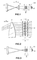
- Fig. 1 illustrates an image projector apparatus 100 having an optical system in accordance with a first embodiment of the present invention.
- the image projector apparatus 100 includes a light source 10, an LCD 11, a projection lens 12 and a projection screen 13, which may be similar to those of the projector 45 of Fig. 10.
- the image projector apparatus 100 further includes first and second micro multi-lens devices 1 and 2, respectively.
- the image projector apparatus still further includes a signal processing device and an optical control circuit, which may function in manner similar to that of the signal processing device 43 and the optical control circuit 44 of the projector 45 of Fig. 10.
- the LCD 11 includes a plurality of pixels, such as approximately 300,000 pixels.
- the first micro multi-lens device 1 includes a plurality of microlenses which are each adapted for respectively converging received light to one of the pixels on a light incident surface 11a of the LCD 11.
- the second micro multi-lens device 2 includes a plurality of microlenses which are each adapted for respectively collimating light transmitted through one of the pixels from a light radiating surface 11b of the LCD 11.
- the collimated light from each of the microlenses of the second micro multi-lens device 2 is projected onto the projection lens 12 which, in turn, is adapted to expand the incident light by positive refraction and to project the light onto a projection screen 13 so as to produce an image thereon.
- the micro multi-lens device 1, the LCD 11 and the micro multi-lens device 2 may be integrally arranged so as to form an image information radiating portion A as shown in Fig. 1.
- the image projector apparatus 100 includes a signal processing device and an optical control circuit.
- a control signal which is utilized for providing image information, may be produced from an input image signal and supplied to the LCD 11.
- the LCD 11 controls the light volume transmitted through each of the pixels.
- Fig. 2 illustrates a cross-sectional side view of an enlarged portion of the image projector apparatus 100 of Fig. 1.
- the LCD 11 includes a shielding mask 11m which is adapted to control or limit the light supplied to each of the pixels 11d.
- each of the microlenses of the micro multi-lens devices 1 and 2 are respectively arranged so as to correspond to one of the pixels 11d.
- the micro multi-lens devices 1 and 2 may function in a manner similar to a relay lens.
- collimated light from the light source 10 (Fig. 1) is projected to each of the microlenses of the micro multi-lens device 1, whereupon the light of each microlens is converged to a corresponding one of the pixels.
- the light from each of the pixels is respectively projected to a corresponding one of the microlenses of the micro multi-lens device 2, whereupon the incident light is collimated and radiated therefrom so as to be projected on the projection lens 12.
- the projection lens 12 projects each of the light beams onto the projection screen 13.
- the image projector apparatus 100 uses the light from the light source 10 in an effective manner so as to eliminate or minimize the reduction in the luminance level thereof, which might otherwise occur, and provides an image picture on the projection screen 13 having acceptable picture quality, unlike the grainy and unacceptable picture obtained by using the projector 45 of Fig. 10. That is, converging the light from the light source 10 by the micro multi-lens device 1, as previously described, is effectively similar to enlarging the "open area" of the pixels 11d. Further, collimating the transmitted light from each of the pixels 11d by the micro multi-lens device 2, as previously described, improves the resolution, and accordingly the picture quality, of the displayed image.
- the projection lens 12 may be located near or adjacent to the micro multi-lens device 2 and integrally formed with the image information radiating portion A so as to form an optical block B as illustrated in Fig. 3.
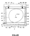
- the optical block B of an image projector apparatus 101 will now be more fully described with reference to Figs. 4A and 4B.
- the optical block B generally includes the image information radiating portion A (which includes the first and second micro multi-lens devices 1 and 2, and the LCD 11), the projecting lens 12, and holding members 14 and 15.
- the holding members 14 and 15 are provided for securing the first and second micro multi-lens devices 1 and 2, respectively, the LCD 11, and the projection lens 12.
- the first micro multi-lens device 1, the LCD 11 and the second micro multi-lens device 2, each of which is arranged as in the previously described image information radiating portion A, are positioned adjacent to surfaces 14c and 15c of the holding members 14 and 15, respectively, so as to be secured therein.
- Each of the first and second micro multi-lens devices 1 and 2, respectively, and the LCD 11 has a substantially similar square or rectangular shape with a length L.
- the projection lens 12 which may have a diameter larger than the length of the image information radiating portion A, is positioned adjacent to a light radiating surface 2a of the micro multi-lens device 2.
- the projection lens 12 is contained within a holding member 49 as shown in Fig. 4B.
- such holding member 49 includes a spring guide 16 having ends 16a and 16b, shafts 16c and 16d, and slide guides 20.
- Springs 17 and 18, which may be compression-type springs, are wound around the shafts 16c and 16d, respectively.
- the holding member 49 is positioned such that the spring guide 16, with its rolled up ends 16a and 16b, is within a recess portion 14a of the holding member 14 and the shafts 16c and 16d are respectively aligned with holes 47 and 48 of the holding member 14. In such position, the compression-type springs 17 and 18 press against a surface 14b of the holding member 14 so as to exert a force on the spring guide 16 in the direction of the arrow C.
- the holding member 49 is further positioned such that slide guides 20 lie within slide openings 45 of side members 46.
- the holding member 49 is further positioned so as to be in contact with the holding member 15.
- Such holding member 15 is adapted to impose a force upon the holding member 49 so as to cause the same to move in a direction indicated by the arrow E (Fig. 4B).
- the holding member 15 includes members 15A, 15B and 15C.
- the member 15A is utilized for securing the image information radiating portion A in the manner previously described.
- the member 15B which includes a surface 15a and a sloped surface 15b, is adapted to be slidable between the holding member 49 and the member 15C.
- the member 15C includes a sloped surface 15c which corresponds to that of the sloped surface 15b and which contacts the same.
- the member 15C further includes a hole 51 through which a shaft coupled to an adjusting knob 19 is inserted.
- the hole 51 is a threaded hole and the shaft coupled to the knob 19 includes a threaded portion. The inserted end of the shaft coupled to the adjusting knob is attached to the member 15B.
- the bearing end of the shaft coupled thereto exerts a force on the member 15B, thereby causing the member 15B to move in one direction along the D direction.
- the holding member 49 is moved or displaced in one direction along the E direction due to the force exerted thereon by the springs 17 and 18 (and possibly gravity) while being guided by the slide guides 20 in the slide openings 45, thereby causing the projection lens 12 to be similarly moved or displaced.
- the member 15B is caused to move along the D direction in the opposite direction, thereby causing the holding member 49 to be moved along the E direction in the opposite direction. Accordingly, in this latter situation, the projection lens 12 is caused to be similarly moved or displaced along the same E direction in the opposite direction.
- the image projector apparatus 101 may be used in an airplane or the like. Accordingly, in such situation as previously described, the image projector apparatus is normally positioned in a location, such as suspended from the ceiling of the aircraft, so as not to disturb the passengers and the projection screen 13 is desirably arranged so that passengers can readily view an image displayed thereon. In such arrangement, the projector is typically positioned so as to be inclined in a downward direction relative to the projection screen (see Fig. 11) and, as a result, a keystone distortion may be produced as previously described.
- Such keystone distortion may be eliminated by shifting the projection lens 12 relative to the LCD 11.
- shifting the projection lens 12 by moving the projection lens 12 such that an optical axis C PL thereof is shifted in a direction, such as in a direction perpendicular to the C PL axis or in the E direction, so as to be offset from a picture center axis C LCD of the LCD 11, keystone distortion may be eliminated.
- Such shifting of the projection lens 12, while the LCD 11 remains fixed causes the image from the LCD and projected on the screen 13 to be moved by parallel translation in the direction of movement of the projection lens.
- An example of such offset is illustrated in Fig. 4B, where the projection lens 12 has been moved so that the optical center axis C PL is lower than the picture center axis C LCD .
- FIG. 9 An example of a light path obtained by using the above-described arrangement, in which the optical center axis C PL of the projection lens 12 has been shifted relative to the picture center axis C LCD , is illustrated in Fig. 9.
- the LCD 11, the projection lens 12 and the projection screen 13 are substantially parallel to each other.
- such technique of moving the projection lens 12, besides compensating for keystone distortion as previously described, also permits the image projector apparatus 101 to be mounted parallel to the ceiling of the aircraft, as illustrated in Fig. 8. That is, in such mounting arrangement, by moving or adjusting the projection lens 12, an image can be moved or adjusted accordingly so as to be properly displayed on the projection screen 13.
- the surface(s) of the LCD 11 and the display surface of the projection screen 13 are parallel to each other, thereby eliminating keystone distortion.
- other mounting arrangements between the image projector apparatus 101 and the projection screen 13 may be employed.
- the image projector apparatus 101 can move or adjust the projection lens 12 and thereby provide an image for display on the screen 13 with no keystone distortion.
- the centers of the LCD 11 and the projection lens 12 are in-line and are not moveable relative to each other.
- the projection lens 12 can be arranged or set beforehand in the image projector apparatus in its "moved position" and, if minute adjustments are desired, the position of the projection lens 12 can be adjusted accordingly by use of the knob 19 or similar such device.
- Fig. 5 illustrates a portion 102 of an image projector apparatus which generally includes an optical block B' having an image information radiating portion A' and a projection lens 112, holding members 114 and 115, a second projection lens 21, lens supporting members 22 and 23, and horizontal movement extending members 25 and 26.
- the portion 102 may be utilized in an image projector apparatus having a light source, such as the light source 10 (Figs. 1 and 3), which, in turn, may be used with a projection screen, such as projection screen 13 (Figs. 1 and 3).
- the image information radiating portion A' and the projection lens 112 are arranged to form the optical block B' and are secured by use of the holding members 114 and 115 in a manner similar to that previously described with reference to Fig. 4A except that no adjustment mechanism is provided for the projection lens 112. That is, in the portion 102, the projection lens 112 is fixedly mounted. Further, the image information radiating portion A' has a length L' which is substantially the same as the diameter of the projection lens 112. As is to be appreciated, selecting such sizes for the image information radiating portion A' and the projection lens 112 facilitates the fabrication of the optical block B'.
- the second projection lens 21, which is arranged between the projection lens 112 and the projection screen 13, is adapted to be moved in two directions, that is, along the directions indicated by E and F in Fig. 5.
- the lens supporting member 22 includes a mechanism (not shown) for causing a V-shaped member (not shown) included therein to be moved in response to the rotation or movement of an adjustment knob, which may be similar to the knob 19. As a result, the projection lens 21 may be moved in the E direction.
- the other end of the projection lens 21 is secured in a holding section 23a in the lens supporting member 23.
- the lens supporting member 23 has a recess portion 23b.
- a spring 24, such as a compression type spring, is arranged between the recess portion 23b and the holding section 23a. As is to be appreciated, the spring 24 may be compressed or expanded in response to the movement of the projection lens 21 and, regardless, the spring causes a holding force to be exerted on the projection lens 21 so as to securely hold the projection lens 21.
- the projection lens 21 may be moved or shifted in the E direction, which is normal to the optical center axis C PL' .
- Such shifting enables light from the portion 102 to be directed in a desired direction for display on the screen 13, without keystone distortion, even with the image projector apparatus mounted in a horizontal position, such as on the ceiling of an aircraft.
- the lens supporting member 22 is slidably attached on a rail 27 which, in turn, is arranged on a surface 25a of the horizontal movement extending member 25.
- the lens supporting member 23 is slidably attached on a rail 28 which, in turn, is arranged on a surface 26a of the horizontal movement extending member 26.
- Such arrangement allows the lens supporting members 22 and 23 to be respectively moved along the rails 27 and 28.
- the horizontal movement extending members 25 and 26 and the rails 27 and 28 are positioned so that such movement is along the F direction, which is substantially parallel to the optical center axis C PL' .
- the optical block B' is held by holding members 114 and 115 which have surfaces 114d and 115d respectively arranged so as to be adjacent to or in contact with horizontal movement extending members 25 and 26.
- the projection lens 21 may be moved in the F direction (i.e., parallel to the optical center axis C PL' ) within a predetermined range, such as from the projection lens 112 to a position twice the focal length (i.e., 2f) of the projection lens 112.
- the light beam from the projection lens 112 converges at a focal length f, in which the diameter of the light beam gradually diminishes throughout such length.
- the diameter of the light beam from the projection lens 112 equals the diameter of the light beam initially radiated from the projection lens 112.
- the projection lens 21, which may be moved in the range from the projection lens 112 or from the focal length f to the focal length 2f, can have a diameter which is substantially the same as or smaller than that of the projection lens 112.
- Fig. 6 illustrates an arrangement and mechanism for mounting an image projector apparatus embodying the invention to the ceiling of an aircraft or the like.
- the image projector apparatus is connected to the ceiling of the aircraft by four pivotable arm members 31, two of which are preferably connected to two opposite sides of the image projector apparatus.
- Such arm members 31 enable the image projector apparatus to be rotatably moved to selected positions while being maintained in an orientation (e.g., a horizontal orientation) such that the optical center axis of the projection lens(es) and the picture center axis of the LCD are substantially parallel to the ceiling of the aircraft.
- a circuit 36 of the image projector apparatus which may be utilized for supplying signals to and from the apparatus, may be located in the recess portion 32, or alternately may be located in an adjacent area thereto.
- Fig. 6 illustrates the image projector apparatus in three horizontal positions obtained by rotatably moving the apparatus as above described. That is, reference numeral 33 illustrates the projector apparatus in a recess portion 32 of the ceiling of the aircraft. As is to be appreciated, the projector apparatus may be placed in the recess portion 32 when not in operation.
- Reference numeral 35 illustrates the projector apparatus in an operating location wherein images may be projected therefrom as shown in Fig. 6.
- Reference numeral 34 illustrates the projector apparatus in an intermediate position between the operating and the non-operating locations.
- Fig. 7 illustrates an alternative arrangement for a light source for use with the present image projector apparatus.
- a light source 40 is located in a position vertical to that of the previously described light source 10 and a mirror 41 is utilized to project collimated light from the light source to the optical block. Due to such arrangement, the length of the image projector apparatus may be reduced so as to have a relatively small length such as, for example, approximately 4 inches. As a result of such small length, the projector apparatus may have an overall relatively small size and relatively low weight. Such small size may be advantageous for enabling mounting of an projector apparatus in a location with limited space, such as on the ceiling on an aircraft where, as is to be appreciated, space may be scarce. Additionally, in such arrangement, the light source 40 may be substantially removed from the optical block, thereby reducing or minimizing any adverse effects in the optical block or projection lens due to the heat produced by the light source.
- the present image projector apparatus uses the amount of light radiated from the light source in a relatively highly efficient manner so as to improve the luminance of the image and provide a picture having relatively high quality.
- a grainy appearance in the displayed picture which may otherwise occur during focusing of the picture due to the relatively small openings associated with each pixel, is avoided.
- a projection lens to be shifted in a direction normal or vertical to the optical center axis of the projection lens, or by fixedly arranging the projection lens in such shifted position, a picture may be displayed in a desired direction without any keystone distortion.
- the mechanism used to shift or adjust the projection lens can be relatively easily and inexpensively constructed.
- the second projection lens which is arranged between the first projection lens and the projection screen, may be shifted in a direction normal or vertical to the optical center axis of the projection lenses, thereby permitting a picture to be moved by parallel translation so as to be displayed in a desired direction without any keystone distortion.
- light may be transmitted from the LCD with relatively high efficiency so as to provide a projected image with a relatively high luminance level.
- such arrangement of the first and second projection lenses enables the size of an image to displayed to be relatively easily controlled, without being sensitive to the focus of such image.
- the image projector apparatus embodying the invention produces an image having a relatively high luminance level for display on a projection screen with no keystone distortion.
- the displayed image has a relatively high picture quality.
- Such present projector apparatus may have a relatively small size and may be easily and inexpensively constructed so as to minimize the cost thereof.
- the projection lens 12 was not described as being adapted to move in a direction normal or vertical to the optical center axis of the projection lens, such apparatus is not so limited and may be constructed so as to enable the projection lens to be moved or shifted in a manner similar to that described with reference to Figs. 4A and 4B.
- one projection lens was adapted to be moved or positioned such that an optical center axis of the projection lens is offset from a picture center axis of the LCD
- the present invention is not so limited.
- the optical block with the LCD may be moved or positioned such that the picture center axis of the LCD is offset from the optical center axis of the projection lens.
Landscapes
- Physics & Mathematics (AREA)
- Nonlinear Science (AREA)
- Chemical & Material Sciences (AREA)
- Crystallography & Structural Chemistry (AREA)
- Multimedia (AREA)
- Signal Processing (AREA)
- Engineering & Computer Science (AREA)
- Mathematical Physics (AREA)
- General Physics & Mathematics (AREA)
- Optics & Photonics (AREA)
- Liquid Crystal (AREA)
- Projection Apparatus (AREA)
- Transforming Electric Information Into Light Information (AREA)
Description
- This invention relates to image projection apparatus for producing an image for display and, more particularly (but not exclusively), to such apparatus in which a light beam from a light source is transmitted through an image medium so as to provide the light with image information and project the light therefrom.
- Transmission light adjusting image projectors may increase the size of a picture so as to enable a number of people to view the picture. An example of a previously proposed such projector is illustrated in Fig. 10 of the accompanying drawings. As shown therein, a
projector 45 generally includes alight source 10, a liquid crystal display (LCD) 11, aprojection lens 12, asignal processing device 43, and anoptical control circuit 44. - In the
projector 45, a light beam is radiated from thelight source 10 to a plurality of pixels (not shown) contained in theLCD 11. An image signal is supplied from aninput terminal 42 to thesignal processing device 43, whereupon the image signal is processed in a predetermined manner and supplied therefrom to theoptical control circuit 44, in turn, generates an optical control signal in accordance with the processed image signal. The optical control signal is supplied to theLCD 11 so as to control the opening and closing of a shutter of the LCD, thereby controlling the transmittance of each pixel of the LCD. As a result, an image may be projected from theLCD 11 through theprojection lens 12 onto aprojection screen 13. - In the
projector 45, thelight source 10 normally radiates a relatively high intensity level of light to compensate for the reduction of luminance caused by the relatively high expansion or enlargement of an image. Further, each of the pixels in theLCD 11 has a relatively small opening corresponding thereto for enabling light transmission. As a result, the luminance level of the image radiated from the LCD and projected onto theprojection screen 13 is relatively low. Furthermore, the operating life of a lamp typically used as thelight source 10 is relatively short and the power consumption is relatively high. - Thus, it is desirable to effectively utilize the radiated light from the
light source 10 and to increase the efficiency of the radiated light transmitted through theLCD 11 so as to eliminate or minimize the amount in which the luminance level is lowered. Such increased efficiency may enable a lamp which provides a lower intensity level of light, and which has a lower power consumption and dissipates a corresponding lesser amount of heat, to be used. - The sizes of the open portions of the
LCD 11, or opening ratio, which respectively correspond to the pixels, are controlled by a shielding mask (not shown), which may be arranged on the incident side of the LCD. By decreasing the area of the shielding mask, the size of the open portions of the LCD may be increased as viewed from the incident surface thereof. - Due to the shielding mask and the relatively small sized open portions of the
LCD 11, and when the distance from thescreen 13 is increased and the picture is enlarged, the image projected on the projection screen may appear grainy, thereby resulting in an image or picture having relatively poor quality. - Further, as shown in Fig. 10, the distance between the
projection lens 12 and theprojection screen 13 is represented by "a", while the distance between theLCD 11 and the projection lens is represented by "b". Accordingly, the focal length of theprojection lens 12 may be determined by the following equation: - As a result of the distances a and b, the image projected on the projected
screen 13 is approximately b/a times larger than the image on the LCD panel. As is apparent from equation 1, the focus of the image is dependent upon the distance from theprojection screen 13. - The
projector 45 may be utilized in an airplane or the like. In such situation, theprojector 45 is suspended from the ceiling so as not to disturb the passengers and theprojection screen 13 is positioned so as to be visible by the passengers. Due to such positioning of theprojector 45 and theprojection screen 13, a center axis of the projector is not perpendicular to the projection screen. As a result, a so-called keystone distortion may be produced. Fig. 11 illustrates such arrangement between theprojector 45 and theprojection screen 13. - As an example of such keystone distortion, consider the situation in which an image of a square object is radiated from the
projector 45 for display on theprojection screen 13, in which the projector and projection screen are mounted in an airplane in the manner previously described. In this situation, instead of a square shape, the object displayed on theprojection screen 13 has a trapezoidal shape. - Such keystone distortion may be reduced by using a
projection lens 12 having a relatively large diameter. However, using such large diameter projection lens has several disadvantages. That is, such projection lens may cause the image light radiated therefrom to have a relatively large diameter, thereby lowering the light volume or luminance level of the image projected on theprojection screen 13. Further, as is to be appreciated, the use of such large diameter projection lens may increase the size and cost of theprojector 45. - The size of the
projector 45 is normally relatively large. That is, as previously described, the projection lens used to reduce keystone distortion is relatively large and, as such, causes the projector to be relatively large. However, even the "other" projection lens has a large diameter which still causes the projector to be relatively large. Further, due to the distance b normally required between theLCD 11 and theprojection lens 12, theprojector 45 typically has a relatively large length or depth. Accordingly, due to the diameter of the projection lens and the distance b, it is difficult to construct theprojector 45 so as to have a relatively small size. - Thus, the prior art has failed to provide a relatively small-sized and low cost projector for producing an image for display on a projection screen having relatively good picture quality, which is capable of correcting keystone distortion and adjusting the focus.
- European Patent Application EP-A-0 516 479 discloses several projection-type liquid crystal display apparatuses. Two such apparatuses, described with reference to Figs. 6 and 7 and Fig. 8 and 9 of EP-A-0 516 479, respecctively, comprise a lamp for supplying light, a liquid crystal panel which receives light from the lamp, a projecting lens which is spaced from the liquid crystal panel and receives light from the panel, and a projection scrren for receiving light from the projection lens. The liquid crystal panel includes a liquid crystal layer having a plurality of microlenses on each side thereof. In the apparatus of Figs. 6 and 7 of EP-A-0 516 479, the light incident on the projecting lens is received via a dichroic prism, disposed between the panel and the projecting lens.
- According to the invention there is provided an image projecting apparatus for producing an image display on a projection screen, said apparatus comprising:
- means for supplying light;
- first lens means having a plurality of first microlenses each arranged to receive light from said light supply means and to respectively project the received light therefrom;
- a liquid crystal display having a plurality of pixels arranged in matrix form and a shielding mask arranged adjacent to said plurality of pixels so as to separate each of said pixels, each of said pixels being respectively arranged to receive light from one of said first microlenses and project therefrom respective image light;
- second lens means having a plurality of second microlenses each for receiving the image light from a respective one of said plurality of pixels in said liquid crystal display for projecting parallel image light therefrom; and
- projection lens means for receiving the parallel image light from each of said second microlenses for projecting the same onto said projection screen;
- wherein said projection lens means comprises a projection lens positioned near or adjacent to said second lens means so as to form, with said second lens means, said liquid crystal display and said first lens means, an optical block.
-
- Embodiments of the invention described hereinbelow provide image projecting apparatuses which overcome at least partially one or more of the above-described problems associated with the prior art.
- More specifically, the embodiments of the invention described hereinbelow provide:
- an image projecting apparatus having an image information radiating unit having a LCD, and first and second lens devices each having a plurality of microlenses and arranged adjacent to an incident side and a radiating side of the LCD, respectively, for effectively utilizing light supplied from a light source so as to provide an image for eventual display on a projection screen having relatively high picture quality;
- an image projecting apparatus as aforesaid in which an optical center axis of a projection lens arranged to receive image light from an image information radiating unit may be shifted or positioned so as to be offset from an image center axis of the LCD as to produce an image for display on the projection screen without any keystone distortion;
- an image projecting apparatus as aforesaid in which a projection lens may be moved along an optical center axis so as to adjust an image displayed on the projection screen;
- an image projecting apparatus as aforesaid in which another projection lens is arranged between the image information radiating unit and the first-mentioned projection lens so as to enable the desired size of the displayed picture to be relatively easily controlled without being sensitive to the focus thereof;
- an image projecting apparatus as aforesaid which has a relatively small size and which can be fabricated for a relatively low cost; and
- an image projecting apparatus as aforesaid which is arranged to be mounted to the ceiling of an aircraft or the like.
-
- The invention will now be further described, by way of illustrative and non-limiting example, with reference to the accompanying drawings, in which corresponding components are identified by the same reference signs, and in which:
- Fig. 1 is a schematic diagram of an image projector apparatus;
- Fig. 2 is a schematic diagram of a cross-sectional side view of an image information radiating portion of the image projector apparatus of Fig. 1;
- Fig. 3 is a schematic diagram of the image projector apparatus of Fig. 1 having an optical block formed of the image information radiating portion and a projection lens;
- Fig. 4A is a schematic diagram of a side view of the optical block of Fig. 3;
- Fig. 4B is a schematic diagram of a back view of the projection lens in the optical block of Fig. 3;
- Fig. 5 is a schematic diagram of an image projector apparatus according the invention;
- Fig. 6 is a schematic diagram of a device for holding an image projector apparatus embodying the invention;
- Fig. 7 is a schematic diagram illustrating an alternative position for a light source;
- Fig. 8 is a schematic diagram illustrating the projection of image light from an image projector apparatus embodying the invention onto a projection screen;
- Fig. 9 is a schematic diagram to which reference is made in explaining keystone distortion;
- Fig. 10 is a schematic diagram of a previously proposed transmission light adjusting image projector; and
- Fig. 11 is a schematic diagram illustrating the projection of light from the projector of Fig. 10.
-
- Fig. 1 illustrates an
image projector apparatus 100 having an optical system in accordance with a first embodiment of the present invention. As shown therein, theimage projector apparatus 100 includes alight source 10, anLCD 11, aprojection lens 12 and aprojection screen 13, which may be similar to those of theprojector 45 of Fig. 10. Theimage projector apparatus 100 further includes first and second micromulti-lens devices 1 and 2, respectively. Although not shown, the image projector apparatus still further includes a signal processing device and an optical control circuit, which may function in manner similar to that of thesignal processing device 43 and theoptical control circuit 44 of theprojector 45 of Fig. 10. - As previously described, the
LCD 11 includes a plurality of pixels, such as approximately 300,000 pixels. - In the
image projector apparatus 100, light is radiated from thelight source 10 onto a mirror M whereat the light is collimated and projected onto the first micro multi-lens device 1. The first micro multi-lens device 1 includes a plurality of microlenses which are each adapted for respectively converging received light to one of the pixels on a light incident surface 11a of theLCD 11. The second micromulti-lens device 2 includes a plurality of microlenses which are each adapted for respectively collimating light transmitted through one of the pixels from a light radiating surface 11b of theLCD 11. The collimated light from each of the microlenses of the second micromulti-lens device 2 is projected onto theprojection lens 12 which, in turn, is adapted to expand the incident light by positive refraction and to project the light onto aprojection screen 13 so as to produce an image thereon. The micro multi-lens device 1, theLCD 11 and the micromulti-lens device 2 may be integrally arranged so as to form an image information radiating portion A as shown in Fig. 1. - As previously mentioned, the
image projector apparatus 100 includes a signal processing device and an optical control circuit. In a manner similar to that described with reference to theprojector 45 of Fig. 10, a control signal, which is utilized for providing image information, may be produced from an input image signal and supplied to theLCD 11. In response to such control signal, theLCD 11 controls the light volume transmitted through each of the pixels. - Fig. 2 illustrates a cross-sectional side view of an enlarged portion of the
image projector apparatus 100 of Fig. 1. As shown therein, theLCD 11 includes a shielding mask 11m which is adapted to control or limit the light supplied to each of the pixels 11d. As further shown in Fig. 2, each of the microlenses of the micromulti-lens devices 1 and 2 are respectively arranged so as to correspond to one of the pixels 11d. The micromulti-lens devices 1 and 2 may function in a manner similar to a relay lens. - More specifically, collimated light from the light source 10 (Fig. 1) is projected to each of the microlenses of the micro multi-lens device 1, whereupon the light of each microlens is converged to a corresponding one of the pixels. The light from each of the pixels is respectively projected to a corresponding one of the microlenses of the micro
multi-lens device 2, whereupon the incident light is collimated and radiated therefrom so as to be projected on theprojection lens 12. Theprojection lens 12, which may be a convex type lens, forms a respective light beam, similar to a light spot, corresponding to each pixel lid of theLCD 11. Theprojection lens 12 projects each of the light beams onto theprojection screen 13. - By utilizing the micro
multi-lens devices 1 and 2, theimage projector apparatus 100 uses the light from thelight source 10 in an effective manner so as to eliminate or minimize the reduction in the luminance level thereof, which might otherwise occur, and provides an image picture on theprojection screen 13 having acceptable picture quality, unlike the grainy and unacceptable picture obtained by using theprojector 45 of Fig. 10. That is, converging the light from thelight source 10 by the micro multi-lens device 1, as previously described, is effectively similar to enlarging the "open area" of the pixels 11d. Further, collimating the transmitted light from each of the pixels 11d by the micromulti-lens device 2, as previously described, improves the resolution, and accordingly the picture quality, of the displayed image. - The
projection lens 12, which is located between the micro multi-lens 2 and theprojection screen 13 as illustrated in Fig. 1., may be moved along an X direction (Figs. 1 and 2). - The
projection lens 12 may be located near or adjacent to the micromulti-lens device 2 and integrally formed with the image information radiating portion A so as to form an optical block B as illustrated in Fig. 3. The optical block B of animage projector apparatus 101 will now be more fully described with reference to Figs. 4A and 4B. - As shown in Fig. 4A, the optical block B generally includes the image information radiating portion A (which includes the first and second micro
multi-lens devices 1 and 2, and the LCD 11), the projectinglens 12, and holdingmembers members multi-lens devices 1 and 2, respectively, theLCD 11, and theprojection lens 12. - The first micro multi-lens device 1, the
LCD 11 and the second micromulti-lens device 2, each of which is arranged as in the previously described image information radiating portion A, are positioned adjacent tosurfaces 14c and 15c of the holdingmembers multi-lens devices 1 and 2, respectively, and theLCD 11 has a substantially similar square or rectangular shape with a length L. - The
projection lens 12, which may have a diameter larger than the length of the image information radiating portion A, is positioned adjacent to a light radiating surface 2a of the micromulti-lens device 2. Theprojection lens 12 is contained within a holdingmember 49 as shown in Fig. 4B. As shown in Fig. 4B, such holdingmember 49 includes aspring guide 16 havingends 16a and 16b,shafts 16c and 16d, and slide guides 20.Springs shafts 16c and 16d, respectively. The holdingmember 49 is positioned such that thespring guide 16, with its rolled up ends 16a and 16b, is within a recess portion 14a of the holdingmember 14 and theshafts 16c and 16d are respectively aligned withholes member 14. In such position, the compression-type springs 17 and 18 press against asurface 14b of the holdingmember 14 so as to exert a force on thespring guide 16 in the direction of the arrow C. The holdingmember 49 is further positioned such that slide guides 20 lie withinslide openings 45 ofside members 46. - The holding
member 49 is further positioned so as to be in contact with the holdingmember 15. Such holdingmember 15 is adapted to impose a force upon the holdingmember 49 so as to cause the same to move in a direction indicated by the arrow E (Fig. 4B). More specifically, the holdingmember 15 includesmembers 15A, 15B and 15C. The member 15A is utilized for securing the image information radiating portion A in the manner previously described. The member 15B, which includes a surface 15a and a sloped surface 15b, is adapted to be slidable between the holdingmember 49 and themember 15C. Themember 15C includes a slopedsurface 15c which corresponds to that of the sloped surface 15b and which contacts the same. Themember 15C further includes ahole 51 through which a shaft coupled to an adjustingknob 19 is inserted. Preferably, thehole 51 is a threaded hole and the shaft coupled to theknob 19 includes a threaded portion. The inserted end of the shaft coupled to the adjusting knob is attached to the member 15B. - As is to be appreciated, by rotating the
knob 19 in one direction, the bearing end of the shaft coupled thereto exerts a force on the member 15B, thereby causing the member 15B to move in one direction along the D direction. As a result of such movement of the member 15B, the holdingmember 49 is moved or displaced in one direction along the E direction due to the force exerted thereon by thesprings 17 and 18 (and possibly gravity) while being guided by the slide guides 20 in theslide openings 45, thereby causing theprojection lens 12 to be similarly moved or displaced. By rotating theknob 19 in the other direction, the member 15B is caused to move along the D direction in the opposite direction, thereby causing the holdingmember 49 to be moved along the E direction in the opposite direction. Accordingly, in this latter situation, theprojection lens 12 is caused to be similarly moved or displaced along the same E direction in the opposite direction. - The reason for enabling the
projector 12 of theimage projector apparatus 101 to be selectably movable as described above will now be described. - The
image projector apparatus 101, like theprojector 45, may be used in an airplane or the like. Accordingly, in such situation as previously described, the image projector apparatus is normally positioned in a location, such as suspended from the ceiling of the aircraft, so as not to disturb the passengers and theprojection screen 13 is desirably arranged so that passengers can readily view an image displayed thereon. In such arrangement, the projector is typically positioned so as to be inclined in a downward direction relative to the projection screen (see Fig. 11) and, as a result, a keystone distortion may be produced as previously described. - Such keystone distortion may be eliminated by shifting the
projection lens 12 relative to theLCD 11. In other words, by moving theprojection lens 12 such that an optical axis CPL thereof is shifted in a direction, such as in a direction perpendicular to the CPL axis or in the E direction, so as to be offset from a picture center axis CLCD of theLCD 11, keystone distortion may be eliminated. Such shifting of theprojection lens 12, while theLCD 11 remains fixed, causes the image from the LCD and projected on thescreen 13 to be moved by parallel translation in the direction of movement of the projection lens. An example of such offset is illustrated in Fig. 4B, where theprojection lens 12 has been moved so that the optical center axis CPL is lower than the picture center axis CLCD. - An example of a light path obtained by using the above-described arrangement, in which the optical center axis CPL of the
projection lens 12 has been shifted relative to the picture center axis CLCD, is illustrated in Fig. 9. In this arrangement, theLCD 11, theprojection lens 12 and theprojection screen 13 are substantially parallel to each other. With such an arrangement, the relationship a:b = c:d applies which indicates no keystone distortion. - Further, such technique of moving the
projection lens 12, besides compensating for keystone distortion as previously described, also permits theimage projector apparatus 101 to be mounted parallel to the ceiling of the aircraft, as illustrated in Fig. 8. That is, in such mounting arrangement, by moving or adjusting theprojection lens 12, an image can be moved or adjusted accordingly so as to be properly displayed on theprojection screen 13. In this mounting arrangement, the surface(s) of theLCD 11 and the display surface of theprojection screen 13 are parallel to each other, thereby eliminating keystone distortion. As is to be appreciated, in addition to being mounted on the ceiling, other mounting arrangements between theimage projector apparatus 101 and theprojection screen 13 may be employed. - Thus, the
image projector apparatus 101 can move or adjust theprojection lens 12 and thereby provide an image for display on thescreen 13 with no keystone distortion. On the other hand, in theprojector 45 of Fig. 10, the centers of theLCD 11 and theprojection lens 12 are in-line and are not moveable relative to each other. - Further, if the positions of the
image projector apparatus 101 and theprojection screen 13 are known, the amount of parallel translation of the image or the amount in which theprojection lens 12 is to be moved can be determined. Accordingly, in this situation, theprojection lens 12 can be arranged or set beforehand in the image projector apparatus in its "moved position" and, if minute adjustments are desired, the position of theprojection lens 12 can be adjusted accordingly by use of theknob 19 or similar such device. - Another embodiment of the present invention will now be described with reference to Fig. 5.
- Fig. 5 illustrates a portion 102 of an image projector apparatus which generally includes an optical block B' having an image information radiating portion A' and a
projection lens 112, holdingmembers second projection lens 21,lens supporting members movement extending members - In the portion 102, the image information radiating portion A' and the
projection lens 112 are arranged to form the optical block B' and are secured by use of the holdingmembers projection lens 112. That is, in the portion 102, theprojection lens 112 is fixedly mounted. Further, the image information radiating portion A' has a length L' which is substantially the same as the diameter of theprojection lens 112. As is to be appreciated, selecting such sizes for the image information radiating portion A' and theprojection lens 112 facilitates the fabrication of the optical block B'. - In the portion 102, the
second projection lens 21, which is arranged between theprojection lens 112 and theprojection screen 13, is adapted to be moved in two directions, that is, along the directions indicated by E and F in Fig. 5. - With regard to movement along the E direction, one end 21a of the
projection lens 21 is supported and fixedly secured in thelens supporting member 22. Thelens supporting member 22 includes a mechanism (not shown) for causing a V-shaped member (not shown) included therein to be moved in response to the rotation or movement of an adjustment knob, which may be similar to theknob 19. As a result, theprojection lens 21 may be moved in the E direction. The other end of theprojection lens 21 is secured in a holding section 23a in thelens supporting member 23. Thelens supporting member 23 has arecess portion 23b. Aspring 24, such as a compression type spring, is arranged between therecess portion 23b and the holding section 23a. As is to be appreciated, thespring 24 may be compressed or expanded in response to the movement of theprojection lens 21 and, regardless, the spring causes a holding force to be exerted on theprojection lens 21 so as to securely hold theprojection lens 21. - Thus, with the above-described mechanism, the
projection lens 21 may be moved or shifted in the E direction, which is normal to the optical center axis CPL'. Such shifting enables light from the portion 102 to be directed in a desired direction for display on thescreen 13, without keystone distortion, even with the image projector apparatus mounted in a horizontal position, such as on the ceiling of an aircraft. - On the other hand, with regard to movement along the F direction, the
lens supporting member 22 is slidably attached on arail 27 which, in turn, is arranged on a surface 25a of the horizontalmovement extending member 25. Thelens supporting member 23 is slidably attached on arail 28 which, in turn, is arranged on a surface 26a of the horizontalmovement extending member 26. Such arrangement allows thelens supporting members rails movement extending members rails members surfaces 114d and 115d respectively arranged so as to be adjacent to or in contact with horizontalmovement extending members projection lens 21 may be moved in the F direction (i.e., parallel to the optical center axis CPL') within a predetermined range, such as from theprojection lens 112 to a position twice the focal length (i.e., 2f) of theprojection lens 112. - The light beam from the
projection lens 112 converges at a focal length f, in which the diameter of the light beam gradually diminishes throughout such length. At a focal length of 2f, the diameter of the light beam from theprojection lens 112 equals the diameter of the light beam initially radiated from theprojection lens 112. As a result, theprojection lens 21, which may be moved in the range from theprojection lens 112 or from the focal length f to the focal length 2f, can have a diameter which is substantially the same as or smaller than that of theprojection lens 112. - Fig. 6 illustrates an arrangement and mechanism for mounting an image projector apparatus embodying the invention to the ceiling of an aircraft or the like. As shown therein, the image projector apparatus is connected to the ceiling of the aircraft by four
pivotable arm members 31, two of which are preferably connected to two opposite sides of the image projector apparatus.Such arm members 31 enable the image projector apparatus to be rotatably moved to selected positions while being maintained in an orientation (e.g., a horizontal orientation) such that the optical center axis of the projection lens(es) and the picture center axis of the LCD are substantially parallel to the ceiling of the aircraft. Acircuit 36 of the image projector apparatus, which may be utilized for supplying signals to and from the apparatus, may be located in therecess portion 32, or alternately may be located in an adjacent area thereto. - Fig. 6 illustrates the image projector apparatus in three horizontal positions obtained by rotatably moving the apparatus as above described. That is,
reference numeral 33 illustrates the projector apparatus in arecess portion 32 of the ceiling of the aircraft. As is to be appreciated, the projector apparatus may be placed in therecess portion 32 when not in operation.Reference numeral 35 illustrates the projector apparatus in an operating location wherein images may be projected therefrom as shown in Fig. 6.Reference numeral 34 illustrates the projector apparatus in an intermediate position between the operating and the non-operating locations. - Fig. 7 illustrates an alternative arrangement for a light source for use with the present image projector apparatus. In such arrangement, a
light source 40 is located in a position vertical to that of the previously describedlight source 10 and amirror 41 is utilized to project collimated light from the light source to the optical block. Due to such arrangement, the length of the image projector apparatus may be reduced so as to have a relatively small length such as, for example, approximately 4 inches. As a result of such small length, the projector apparatus may have an overall relatively small size and relatively low weight. Such small size may be advantageous for enabling mounting of an projector apparatus in a location with limited space, such as on the ceiling on an aircraft where, as is to be appreciated, space may be scarce. Additionally, in such arrangement, thelight source 40 may be substantially removed from the optical block, thereby reducing or minimizing any adverse effects in the optical block or projection lens due to the heat produced by the light source. - As is to be appreciated, in the previously described image projector apparatus using the
light source 10, such light source could be further removed from the optical block in a direction parallel to the optical center axis so as to similarly reduce or minimize any adverse effects due to the heat produced by the light source on the optical block. However, in this situation, the length of the projector apparatus would be increased, thereby increasing the size, weight and the cost thereof. - Therefore, by using the first and second
micro multi-lenses 1 and 2, respectively, the present image projector apparatus uses the amount of light radiated from the light source in a relatively highly efficient manner so as to improve the luminance of the image and provide a picture having relatively high quality. As a result, a grainy appearance in the displayed picture, which may otherwise occur during focusing of the picture due to the relatively small openings associated with each pixel, is avoided. Further, by enabling a projection lens to be shifted in a direction normal or vertical to the optical center axis of the projection lens, or by fixedly arranging the projection lens in such shifted position, a picture may be displayed in a desired direction without any keystone distortion. The mechanism used to shift or adjust the projection lens can be relatively easily and inexpensively constructed. - Furthermore, in the embodiment of the present invention having two projection lenses, the second projection lens, which is arranged between the first projection lens and the projection screen, may be shifted in a direction normal or vertical to the optical center axis of the projection lenses, thereby permitting a picture to be moved by parallel translation so as to be displayed in a desired direction without any keystone distortion. In this embodiment, light may be transmitted from the LCD with relatively high efficiency so as to provide a projected image with a relatively high luminance level. Additionally, such arrangement of the first and second projection lenses enables the size of an image to displayed to be relatively easily controlled, without being sensitive to the focus of such image.
- Furthermore, by moving the light source either in a vertical or horizontal direction away from the optical block, as previously described, thermal related adverse effects on the optical block and the LCD due to heat generated by the light source can be minimized.
- Thus, the image projector apparatus embodying the invention produces an image having a relatively high luminance level for display on a projection screen with no keystone distortion. As a result, the displayed image has a relatively high picture quality. Such present projector apparatus may have a relatively small size and may be easily and inexpensively constructed so as to minimize the cost thereof.
- Although in describing the above
image projector apparatus 100 theprojection lens 12 was not described as being adapted to move in a direction normal or vertical to the optical center axis of the projection lens, such apparatus is not so limited and may be constructed so as to enable the projection lens to be moved or shifted in a manner similar to that described with reference to Figs. 4A and 4B. Further, although in describing the present image projector apparatus one projection lens was adapted to be moved or positioned such that an optical center axis of the projection lens is offset from a picture center axis of the LCD, the present invention is not so limited. For example, as an alternative, the optical block with the LCD may be moved or positioned such that the picture center axis of the LCD is offset from the optical center axis of the projection lens.
Claims (27)
- An image projecting apparatus for producing an image display on a projection screen, said apparatus comprising:means (10; 40) for supplying light;first lens means (1) having a plurality of first microlenses each arranged to receive light from said light supply means and to respectively project the received light therefrom;a liquid crystal display (11) having a plurality of pixels (11d) arranged in matrix form and a shielding mask (11m) arranged adjacent to said plurality of pixels so as to separate each of said pixels, each of said pixels being respectively arranged to receive light from one of said first microlenses and project therefrom respective image light;second lens means (2) having a plurality of second microlenses each for receiving the image light from a respective one of said plurality of pixels (11d) in said liquid crystal display (11) for projecting parallel image light therefrom; andprojection lens means (12; 112, 21) for receiving the parallel image light from each of said second microlenses for projecting the same onto said projection screen;wherein said projection lens means (12; 112, 21) comprises a projection lens (12; 112) positioned near or adjacent to said second lens means (2) so as to form, with said second lens means (2), said liquid crystal display (11) and said first lens means (1), an optical block (B; B').
- Apparatus according to claim 1, wherein said liquid crystal display (11) and said projection lens means (12) have an image center axis and an optical center axis, respectively, and wherein said image center axis and said optical center axis are non-coincident with each other.
- Apparatus according to claim 1, wherein said projection lens means includes a projection lens (12) having a diameter and wherein said first lens means (1), said liquid crystal display (11) and said second lens means (2) form an image information radiating unit (A) having a length associated therewith which is smaller than said diameter of said projection lens.
- Apparatus according to claim 3, comprising means for moving said projection lens (12) in a direction normal to an optical center axis of said projection lens.
- Apparatus according to claim 4, wherein the moving means can move said projection lens (12) so that said optical center axis is non-coincident with an image center axis of said liquid crystal display (11).
- Apparatus according to claim 1, wherein said first lens means (1), said liquid crystal display (11) and said second lens means (2) form an image information radiating unit (A; A') having an image center axis, wherein said projection lens means includes a projection lens (12; 21) having an optical center axis, and wherein means is provided for moving one of said image information radiating unit and said projection lens in a direction normal to said optical center axis and said image center axis.
- Apparatus according to claim 6, wherein said moving means can move said one of said image information radiating unit and said projection lens so that the center axis corresponding to the moved one of said image information radiating unit and said projection lens is non-coincident with the other center axis.
- Apparatus according to claim 7, wherein said moving means can move said projection lens such that the optical center axis of said projection lens is non-coincident with said image center axis of said image information radiating unit.
- Apparatus according to claim 1, wherein said first lens means (1), said liquid crystal display unit (11) and said second lens means (2) form an image information radiating unit (A; A') having an image center axis and wherein said light supply means (40) is positioned such that its center does not lie along said image center axis.
- Apparatus according to claim 9, comprising a mirror (41) for receiving light from said light supply means (40) and for reflecting the received light to said first lens means (1).
- Apparatus according to claim 1, comprising:a projector device constituted by said means (10; 40) for supplying light, said first lens means (1), said liquid crystal display (11), said second lens means (2) and said projection lens means (12; 112, 21); andmeans (31) arranged to be coupled to a ceiling of an aircraft for mounting said projector device thereat and for enabling said projector device to be positioned in a plurality of positions.
- Apparatus according to claim 11, wherein said means (31) for mounting and enabling maintains and positions said projector device in a constant orientation.
- Apparatus according to claim 12, wherein said first lens means (1), said liquid crystal display (11) and said second lens means (2) form an image information radiating unit (A; A') having an image center axis, wherein said projection lens means has an optical axis, and wherein said constant orientation is one in which said image center axis and said optical axis are substantially parallel to the ceiling of said aircraft.
- Apparatus according to claim 1, wherein said projection lens means (112, 21) comprises the projection lens (112) forming part of the optical block (B'), which projection lens (112) - hereinafter referred to as the first projection lens - is for receiving the parallel image light from each of said second microlenses and for projecting the same therefrom, and a second projection lens (21) for receiving the light from said first projection lens (112) and for projecting the same onto said projection screen.
- Apparatus according to claim 14, wherein said first lens means (1), said liquid crystal display (11) and said second lens means (2) form an image information radiating unit (A') having a length associated therewith and wherein said first projection lens (112) has a diameter which is substantially equal to the length of said image information radiating unit (A').
- Apparatus according to claim 14, wherein said first and second projection lenses (112, 21) each have a respective optical axis and wherein said first and second projection lenses are arranged such that the optical axes are non-coincident with each other.
- Apparatus according to claim 14, wherein said first lens means (1), said liquid crystal display (11) and said second lens means (2) form an image information radiating unit (A') having an image center axis, and wherein said first and second projection lenses (112, 21) each have a respective optical axis.
- Apparatus according to claim 17, comprising means for moving one of said image information radiating unit (A') and said first and second projection lenses (112, 21) in a direction normal to said optical center axes and said image center axis.
- Apparatus according to claim 18, wherein said moving means can move said one of said image information radiating unit (A') and said first and second projection lenses (112, 21) so that the center axis corresponding to the moved one of said image information radiating unit and said first and second projection lenses is non-coincident with at least one of the other center axes.
- Apparatus according to claim 19, wherein said moving means can move said second projection lens (21) such that the optical center axis of said second projection lens is non-coincident with the optical center axis of said first projection lens (112) and said image center axis of said image information radiating unit (A').
- Apparatus according to claim 14, wherein said first lens means (1), said liquid crystal display (11) and said second lens means (2) form an image information radiating unit (A') having an image center axis and wherein said light supply means (40) is positioned such that its center does not lie along said image center axis.
- Apparatus according to claim 21, comprising a mirror (41) for receiving light from said light supply means (40) and for reflecting light from said light supply means (40) and for reflecting the received light to said first lens means (1).
- Apparatus according to claim 1, comprising:a projector device constituted by said means (10; 40) for supplying light, said first lens means (1), said liquid crystal display (11), said second lens means (2) and said projection lens means (112, 21), said projection lens means (112, 21) comprising the projection lens (112) forming part of the optical block (B'), which projection lens (112) - hereinafter referred to as the first projection lens - is for receiving the parallel image light from each of said second microlenses and for projecting the same therefrom, and a second projection lens (21) for receiving the light from said first projection lens (112) and for projecting the same onto said projection screen; andmeans (31) arranged to be coupled to a ceiling of an aircraft for mounting said projector device thereat and for enabling said projector device to be positioned in a plurality of positions.
- Apparatus according to claim 23, wherein said means (31) for mounting and enabling maintains and positions said projector device in a constant orientation.
- Apparatus according to claim 24, wherein said first lens means (1), said liquid crystal display (11) and said second lens means (2) form an image information radiating unit (A') having an image center axis, wherein said first and second projection lenses (112, 21) each have a respective optical axis, and wherein said constant orientation is one in which said image center axis and the optical axes are substantially parallel to the ceiling of said aircraft.
- Apparatus according to claim 25, comprising means for moving one of said image information radiating unit (A') and said first and second projection lenses (112, 21) in a direction normal to said optical center axes and said image center axis so as to provide an image for display without any keystone distortion.
- Apparatus according to any one of the preceding claims, comprising means (44) for generating a control signal and for supplying the same to said liquid crystal display (11), said liquid crystal display being responsive to said control signal for controlling the amount of light received by each of said pixels (11d).
Applications Claiming Priority (2)
| Application Number | Priority Date | Filing Date | Title |
|---|---|---|---|
| JP4360122A JPH06202096A (en) | 1992-12-28 | 1992-12-28 | Video projector device |
| JP360122/92 | 1992-12-28 |
Publications (2)
| Publication Number | Publication Date |
|---|---|
| EP0605232A1 EP0605232A1 (en) | 1994-07-06 |
| EP0605232B1 true EP0605232B1 (en) | 1999-03-03 |
Family
ID=18468000
Family Applications (1)
| Application Number | Title | Priority Date | Filing Date |
|---|---|---|---|
| EP93310544A Expired - Lifetime EP0605232B1 (en) | 1992-12-28 | 1993-12-24 | Image projecting apparatus |
Country Status (5)
| Country | Link |
|---|---|
| US (1) | US5500692A (en) |
| EP (1) | EP0605232B1 (en) |
| JP (1) | JPH06202096A (en) |
| KR (1) | KR940017822A (en) |
| DE (1) | DE69323710T2 (en) |
Cited By (1)
| Publication number | Priority date | Publication date | Assignee | Title |
|---|---|---|---|---|
| DE102007038881A1 (en) | 2007-08-17 | 2009-03-12 | Airbus Deutschland Gmbh | Projector of an information display system in vehicles, in particular in aircraft |
Families Citing this family (19)
| Publication number | Priority date | Publication date | Assignee | Title |
|---|---|---|---|---|
| US5768023A (en) * | 1994-06-29 | 1998-06-16 | Fujitsu Limited | Optical apparatus |
| US5606436A (en) * | 1994-11-21 | 1997-02-25 | Proxima Corporation | Liquid crystal projection panel construction and method of making same |
| WO1996021992A2 (en) * | 1995-01-14 | 1996-07-18 | Optica Nova Onab Ab | Method for increased colour reproduction |
| US5860721A (en) * | 1997-06-09 | 1999-01-19 | Electrohome Limited | Optical resizing apparatus |
| KR100630936B1 (en) * | 1999-08-10 | 2006-10-02 | 삼성전자주식회사 | Image Distortion Correction Device of Light Projection Display |
| US6371616B1 (en) * | 1999-11-12 | 2002-04-16 | International Business Machines Corporation | Information processing miniature devices with embedded projectors |
| US6563101B1 (en) | 2000-01-19 | 2003-05-13 | Barclay J. Tullis | Non-rectilinear sensor arrays for tracking an image |
| DE102004031700B4 (en) * | 2004-06-30 | 2010-02-18 | Airbus Deutschland Gmbh | Airplane with information display system |
| US7178735B2 (en) * | 2004-11-15 | 2007-02-20 | Kuo Ching Chiang | Multi-function portable communication device |
| US9083781B2 (en) | 2004-11-15 | 2015-07-14 | Bascule Development Ag Llc | Portable image-capturing device with embedded projector |
| US20060238657A1 (en) * | 2005-03-17 | 2006-10-26 | Paul Bullwinkel | Compact projection system |
| WO2007097122A1 (en) * | 2006-02-21 | 2007-08-30 | Matsushita Electric Works, Ltd. | Image display apparatus and image distortion correction method of the same |
| JP4941887B2 (en) * | 2006-07-26 | 2012-05-30 | 東芝ホームテクノ株式会社 | Display device |
| TW201029027A (en) * | 2009-01-16 | 2010-08-01 | Cyntec Co Ltd | Method for adjusting inductance of choke and method for designing choke |
| JP2010169847A (en) * | 2009-01-22 | 2010-08-05 | Sony Corp | Spatial image display |
| WO2011027254A1 (en) * | 2009-09-07 | 2011-03-10 | Koninklijke Philips Electronics N.V. | Picture projector |
| TWI459119B (en) * | 2010-10-05 | 2014-11-01 | Bascule Dev Ag Llc | Mini-color image projector |
| CN103365060B (en) * | 2013-07-17 | 2015-11-18 | 保利影业投资有限公司 | A kind of window for film projector |
| JP6880701B2 (en) | 2016-12-19 | 2021-06-02 | セイコーエプソン株式会社 | Electro-optics and electronic equipment |
Family Cites Families (11)
| Publication number | Priority date | Publication date | Assignee | Title |
|---|---|---|---|---|
| JPS6062131A (en) * | 1983-09-14 | 1985-04-10 | Toshiba Corp | Semicoductor device |
| US4639106A (en) * | 1985-04-26 | 1987-01-27 | Sundstrand Data Control, Inc. | Aircraft video projection system |
| JPH0289025A (en) * | 1988-09-26 | 1990-03-29 | Nippon Sheet Glass Co Ltd | Liquid crystal panel |
| JPH0642126B2 (en) * | 1988-10-26 | 1994-06-01 | シャープ株式会社 | Projection type image display device |
| JPH02287586A (en) * | 1989-04-28 | 1990-11-27 | Sony Corp | Liquid crystal projector |
| US5261645A (en) * | 1989-07-31 | 1993-11-16 | Huffman Charles E | Projector ceiling lift |
| JPH03140920A (en) * | 1989-10-26 | 1991-06-14 | Matsushita Electric Ind Co Ltd | Projection type display device and liquid crystal display device used for this projection type display device |
| JPH03175436A (en) * | 1989-12-05 | 1991-07-30 | Matsushita Electric Ind Co Ltd | Color image projection device and its liquid crystal display device |
| JP2552389B2 (en) * | 1990-02-01 | 1996-11-13 | シャープ株式会社 | Transmissive display |
| JP2849492B2 (en) * | 1991-05-31 | 1999-01-20 | シャープ株式会社 | Projection type liquid crystal display |
| JPH05346578A (en) * | 1992-06-15 | 1993-12-27 | Nippon Sheet Glass Co Ltd | Liquid crystal display panel |
-
1992
- 1992-12-28 JP JP4360122A patent/JPH06202096A/en not_active Withdrawn
-
1993
- 1993-12-24 EP EP93310544A patent/EP0605232B1/en not_active Expired - Lifetime
- 1993-12-24 DE DE69323710T patent/DE69323710T2/en not_active Expired - Fee Related
- 1993-12-27 US US08/173,043 patent/US5500692A/en not_active Expired - Fee Related
- 1993-12-28 KR KR1019930030120A patent/KR940017822A/en not_active Withdrawn
Cited By (2)
| Publication number | Priority date | Publication date | Assignee | Title |
|---|---|---|---|---|
| DE102007038881A1 (en) | 2007-08-17 | 2009-03-12 | Airbus Deutschland Gmbh | Projector of an information display system in vehicles, in particular in aircraft |
| US8192028B2 (en) | 2007-08-17 | 2012-06-05 | Airbus Operations Gmbh | Projector of an information display system in vehicles, in particular in aircraft |
Also Published As
| Publication number | Publication date |
|---|---|
| JPH06202096A (en) | 1994-07-22 |
| EP0605232A1 (en) | 1994-07-06 |
| US5500692A (en) | 1996-03-19 |
| DE69323710T2 (en) | 1999-07-22 |
| KR940017822A (en) | 1994-07-27 |
| DE69323710D1 (en) | 1999-04-08 |
Similar Documents
| Publication | Publication Date | Title |
|---|---|---|
| EP0605232B1 (en) | Image projecting apparatus | |
| US8444271B2 (en) | System and method for reducing visible speckle in a projection visual display system | |
| KR100938029B1 (en) | Projector | |
| US5930050A (en) | Anamorphic lens for providing wide-screen images generated by a spatial light modulator | |
| US6923546B2 (en) | Projection optical system and projection type display apparatus using the same | |
| US6113240A (en) | Reflection type projector | |
| US6755534B2 (en) | Prismatic optical display | |
| US6781563B2 (en) | Multivision device | |
| KR20010033854A (en) | Projection system with projector and deflection mirror | |
| US20080123062A1 (en) | Projector | |
| CN102640037A (en) | Optical projection system with curved speckle reduction element surface | |
| JPH06235883A (en) | Video projector | |
| US20060066810A1 (en) | Multi-view autostereoscopic projection system using single projection lens unit | |
| EP0196335A1 (en) | Projector | |
| JPH0519346A (en) | Projection type image display device | |
| US8379322B2 (en) | Integrated asphere design for display | |
| US7545446B2 (en) | Offner relay for projection system | |
| JP3642183B2 (en) | Rear projection display | |
| JPH05158151A (en) | Rear projection display | |
| US4974958A (en) | Projecting optical apparatus having no trapezoidal distortion | |
| KR200155567Y1 (en) | Focus Adjuster on Projection TV | |
| JP3088145U (en) | Movable rear projection type projector device | |
| JP3087322U (en) | Movable rear projection type projector device | |
| KR0170980B1 (en) | Projection stop with adjustable light intensity of projection image display device | |
| KR0173713B1 (en) | Position adjusting device of optical path controller of projection image display device |
Legal Events
| Date | Code | Title | Description |
|---|---|---|---|
| PUAI | Public reference made under article 153(3) epc to a published international application that has entered the european phase |
Free format text: ORIGINAL CODE: 0009012 |
|
| AK | Designated contracting states |
Kind code of ref document: A1 Designated state(s): DE FR GB |
|
| 17P | Request for examination filed |
Effective date: 19941124 |
|
| 17Q | First examination report despatched |
Effective date: 19960731 |
|
| GRAG | Despatch of communication of intention to grant |
Free format text: ORIGINAL CODE: EPIDOS AGRA |
|
| GRAG | Despatch of communication of intention to grant |
Free format text: ORIGINAL CODE: EPIDOS AGRA |
|
| GRAH | Despatch of communication of intention to grant a patent |
Free format text: ORIGINAL CODE: EPIDOS IGRA |
|
| GRAH | Despatch of communication of intention to grant a patent |
Free format text: ORIGINAL CODE: EPIDOS IGRA |
|
| GRAH | Despatch of communication of intention to grant a patent |
Free format text: ORIGINAL CODE: EPIDOS IGRA |
|
| GRAA | (expected) grant |
Free format text: ORIGINAL CODE: 0009210 |
|
| AK | Designated contracting states |
Kind code of ref document: B1 Designated state(s): DE FR GB |
|
| REF | Corresponds to: |
Ref document number: 69323710 Country of ref document: DE Date of ref document: 19990408 |
|
| ET | Fr: translation filed | ||
| PLBE | No opposition filed within time limit |
Free format text: ORIGINAL CODE: 0009261 |
|
| STAA | Information on the status of an ep patent application or granted ep patent |
Free format text: STATUS: NO OPPOSITION FILED WITHIN TIME LIMIT |
|
| 26N | No opposition filed | ||
| PGFP | Annual fee paid to national office [announced via postgrant information from national office to epo] |
Ref country code: FR Payment date: 20011212 Year of fee payment: 9 |
|
| PGFP | Annual fee paid to national office [announced via postgrant information from national office to epo] |
Ref country code: GB Payment date: 20011227 Year of fee payment: 9 |
|
| REG | Reference to a national code |
Ref country code: GB Ref legal event code: IF02 |
|
| PGFP | Annual fee paid to national office [announced via postgrant information from national office to epo] |
Ref country code: DE Payment date: 20020109 Year of fee payment: 9 |
|
| PG25 | Lapsed in a contracting state [announced via postgrant information from national office to epo] |
Ref country code: GB Free format text: LAPSE BECAUSE OF NON-PAYMENT OF DUE FEES Effective date: 20021224 |
|
| PG25 | Lapsed in a contracting state [announced via postgrant information from national office to epo] |
Ref country code: DE Free format text: LAPSE BECAUSE OF NON-PAYMENT OF DUE FEES Effective date: 20030701 |
|
| GBPC | Gb: european patent ceased through non-payment of renewal fee |
Effective date: 20021224 |
|
| PG25 | Lapsed in a contracting state [announced via postgrant information from national office to epo] |
Ref country code: FR Free format text: LAPSE BECAUSE OF NON-PAYMENT OF DUE FEES Effective date: 20030901 |
|
| REG | Reference to a national code |
Ref country code: FR Ref legal event code: ST |