EP0604515B1 - Luminaires - Google Patents
Luminaires Download PDFInfo
- Publication number
- EP0604515B1 EP0604515B1 EP92919753A EP92919753A EP0604515B1 EP 0604515 B1 EP0604515 B1 EP 0604515B1 EP 92919753 A EP92919753 A EP 92919753A EP 92919753 A EP92919753 A EP 92919753A EP 0604515 B1 EP0604515 B1 EP 0604515B1
- Authority
- EP
- European Patent Office
- Prior art keywords
- reflectors
- luminaire
- frame
- lamp
- reflector
- Prior art date
- Legal status (The legal status is an assumption and is not a legal conclusion. Google has not performed a legal analysis and makes no representation as to the accuracy of the status listed.)
- Expired - Lifetime
Links
Images

Classifications
-
- F—MECHANICAL ENGINEERING; LIGHTING; HEATING; WEAPONS; BLASTING
- F21—LIGHTING
- F21V—FUNCTIONAL FEATURES OR DETAILS OF LIGHTING DEVICES OR SYSTEMS THEREOF; STRUCTURAL COMBINATIONS OF LIGHTING DEVICES WITH OTHER ARTICLES, NOT OTHERWISE PROVIDED FOR
- F21V14/00—Controlling the distribution of the light emitted by adjustment of elements
- F21V14/04—Controlling the distribution of the light emitted by adjustment of elements by movement of reflectors
-
- F—MECHANICAL ENGINEERING; LIGHTING; HEATING; WEAPONS; BLASTING
- F21—LIGHTING
- F21V—FUNCTIONAL FEATURES OR DETAILS OF LIGHTING DEVICES OR SYSTEMS THEREOF; STRUCTURAL COMBINATIONS OF LIGHTING DEVICES WITH OTHER ARTICLES, NOT OTHERWISE PROVIDED FOR
- F21V17/00—Fastening of component parts of lighting devices, e.g. shades, globes, refractors, reflectors, filters, screens, grids or protective cages
- F21V17/02—Fastening of component parts of lighting devices, e.g. shades, globes, refractors, reflectors, filters, screens, grids or protective cages with provision for adjustment
Definitions
- This invention relates to luminaires, specifically to those for use in lighting situations in which it is not desired to achieve equal lighting at all positions illuminated by the luminaire.
- luminaire' is meant an apparatus which distributes, filters and/or transforms light from one or more lamps mounted in the apparatus.
- the fixed light distribution does not prove to be a problem.
- lighting situations such as in a subway, where a luminaire of fixed light distribution may result in either a large wastage of light to ensure that all the area is adequately illuminated, which in a subway results in a higher than necessary degree of illumination of the walls and certain parts of the floor surface, or it may result in inadequate lighting of the entire area but not wastage of light.
- each luminaire so as to give the light distribution best suited to the proposed position in which the luminaire is to be mounted. This option, however, is not feasible economically.
- BE-3481944 describes a luminaire having four reflectors; however each reflector is adjustable only about a pivot axis lying in the plane of the reflector and parallel to the plane of a base member of the luminaire. This luminaire accordingly has a restricted range of adjustability of light distribution.
- a luminaire comprising a frame, having at least four reflectors mounted around an aperture in the frame to circumscribe a lamp position and to reflect light emitted from a lamp when in position, and in which the reflectors are pivotally mounted on the frame and are associated with means for fixing their position with respect to the frame, characterised in that each of the four reflectors is angularly adjustable about an axis extending perpendicularly to the frame and has a substantially-triangular base in slidable contact with one surface of an apertured base member of the frame, and the adjacent ends of a pair of reflectors on each side of a median axis of the aperture are engaged by one of a pair of contiguous pivot members.
- the luminaire may be adapted to be located about a fixed lamp, or it may itself include a socket for a lamp.
- the socket (and thus the lamp) may be fixed or it may be movable in the frame relative to the reflectors to vary the pattern and distribution of illumination.
- a luminaire 2 comprises a frame 4 on to which are pivotally attached four reflectors 6, each being attached by, and pivoting about the main axis of, a pivot screw 8, being locked in position by a lock screw 20. Also attached to frame 4 is a lamp holder 10, in which is a lamp 12. Although screws are described, other forms of pivots and clamps could be used.
- Figure 1 is a perspective view of what would be the underside of the luminaire when mounted, as is usual, to direct downwards the light from lamp 12.
- Frame 4 is in the form of a metal box, with a hexagonal aperture 14 in the base 13 of the box.
- the walls 23 of the box 4 are formed with flanges 15 in which are holes 16 by means of which screws or the like may be used to mount the luminaire in a lantern 21 ( Figure 2) able to be mounted at an appropriate height above the path or other surface to be lit at night.
- Frame 4 may, in other embodiments, be of any substantially hollow form determined by the final desired shape of the luminaire.
- a U-shaped bracket 22 Secured to, or integral with, the frame 4 is a U-shaped bracket 22 to which the lampholder 10 may be secured and of which an inside surface 9, opposite the aperture 14, is of a reflective white material or paint.
- Each reflector 6 extends from near the rear reflective surface 9 to base 13, and is attached by at least the pivot screw 8 at one end of the reflector to the base adjacent to an edge of aperture 14.
- the reflectors 6 and screws 8 are arranged so that on each side of the median axis of aperture 14 there are two reflectors 6 fixed with their screws 8 adjacent to each other and the reflectors extending away from each other.
- each reflector 6 has a substantially-triangular base 17 having the individual reflective facets 18 formed by folding the material of the reflector, such as polished aluminium sheet, about parallel fold lines 19.
- each reflector 6 When its respective pivot screw 8 is not tight, each reflector 6 is able to be pivoted about the main axis of the screw, the axis being substantially perpendicular to the base 13, with the base 17 of each reflector in sliding contact with the base 13.
- Each reflector 6 is of sufficient length for its base at all angular positions to overlap the edges of aperture 14.
- Each reflector 6 is of sufficient width, in the plane perpendicular to base 13, for its depth to be substantially the same as that between the base 13 and surface 9.
- each reflector comprises four substantially-rectangular plane facets angled to each other about a fold line, the major axis of each facet running substantially parallel to base 13.
- reflectors 6 are specular reflectors.
- the lamp holder 10 is located between two free ends of the two adjacent reflectors 6.
- the pivot screws 8 are loosely done up, the reflectors 6 may easily be pivoted to alter the light distribution from the luminaire 2.
- the pivot screws 8 are tightened and holes for lock screws 20 drilled and tapped, and the lock screws 20 inserted and tightened so that each reflector is held in position by two screws.
- lock and pivot screws hold each reflector in position during storage, transit and installation. If the reflector as so held is distributing light where needed, then lock screw 20 is kept in place, but otherwise it is removed to permit adjustment of each reflector by pivotal movement of the reflector about its pivot screw 8.
- the range of light distribution patterns achieved may be further widened by the use of different configurations for the reflector surfaces. All the reflectors in one luminaire may have identically-configured surfaces, but it is within the present invention for the reflectors to have different surface configurations and/or reflectivities.
- a further widening of the range of light distribution patterns may also be achieved by allowing the position of the lamp holder, and hence the position of the lamp to be adjustable relative to the bracket 22 and to the frame 4.
- the frame 4 as shown in square in plan, and is able to be secured to a four-sided lantern 21 by means of screws (not shown) extending through the apertures 16 into tapped holes in the lantern body.
- the lantern body 21 comprises a metal or other framework 26 which has a base from which extends an electric cable 28 for the lamp circuitry. While each face of the lantern may have an individual pane of glass 30, it is preferred to insert into the framework a four-sided body of clear plastics material.
- the cap 24 is preferably pivotally mounted in body 21, so as to give ready access to the lampholder and reflectors.
Abstract
Description
- This invention relates to luminaires, specifically to those for use in lighting situations in which it is not desired to achieve equal lighting at all positions illuminated by the luminaire. By the term 'luminaire' is meant an apparatus which distributes, filters and/or transforms light from one or more lamps mounted in the apparatus.
- It is known that in some lighting situations it is desired not to light uniformly the complete surroundings to a luminaire, but to direct the light in particular directions, for example the luminaire for a street light specifically directs in a downwards direction most of the light emitted by the lamp. The distribution of the light is fixed by the luminaire.
- In some situations the fixed light distribution does not prove to be a problem. There are, however, lighting situations, such as in a subway, where a luminaire of fixed light distribution may result in either a large wastage of light to ensure that all the area is adequately illuminated, which in a subway results in a higher than necessary degree of illumination of the walls and certain parts of the floor surface, or it may result in inadequate lighting of the entire area but not wastage of light.
- Theoretically it would be possible individually to manufacture each luminaire so as to give the light distribution best suited to the proposed position in which the luminaire is to be mounted. This option, however, is not feasible economically.
- It is known to manufacture luminaires with two reflectors of which each can swivel relative to a fixed lamp, to vary the distribution of illumination. Patent specifications DE-1094982 and CH-370039 describe such luminaires. It is also known to vary the distribution of illumination by moving the light source relative to the reflectors.
- Neither of these options gives a very satisfactory range of light distribution.
- BE-3481944 describes a luminaire having four reflectors; however each reflector is adjustable only about a pivot axis lying in the plane of the reflector and parallel to the plane of a base member of the luminaire. This luminaire accordingly has a restricted range of adjustability of light distribution.
- According to the present invention there is provided a luminaire comprising a frame, having at least four reflectors mounted around an aperture in the frame to circumscribe a lamp position and to reflect light emitted from a lamp when in position, and in which the reflectors are pivotally mounted on the frame and are associated with means for fixing their position with respect to the frame, characterised in that each of the four reflectors is angularly adjustable about an axis extending perpendicularly to the frame and has a substantially-triangular base in slidable contact with one surface of an apertured base member of the frame, and the adjacent ends of a pair of reflectors on each side of a median axis of the aperture are engaged by one of a pair of contiguous pivot members.
- The luminaire may be adapted to be located about a fixed lamp, or it may itself include a socket for a lamp. The socket (and thus the lamp) may be fixed or it may be movable in the frame relative to the reflectors to vary the pattern and distribution of illumination.
- The present invention will be further described and explained by way of example with reference to the accompanying drawings, in which:
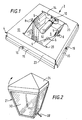
- Figure 1
- shows a perspective view of a luminaire according to the present invention in a preferred embodiment;
- Figure 2
- shows a side elevation of a lantern fitted with a luminaire of the present invention;
- Figure 3
- is a side elevation of the luminaire of Figure 1 in a position in which it throws light down, and
- Figure 4
- is a scrap perspective view of one reflector in position.
- Referring to the drawings, a
luminaire 2 comprises a frame 4 on to which are pivotally attached fourreflectors 6, each being attached by, and pivoting about the main axis of, apivot screw 8, being locked in position by alock screw 20. Also attached to frame 4 is alamp holder 10, in which is alamp 12. Although screws are described, other forms of pivots and clamps could be used. Figure 1 is a perspective view of what would be the underside of the luminaire when mounted, as is usual, to direct downwards the light fromlamp 12. - Frame 4 is in the form of a metal box, with a
hexagonal aperture 14 in thebase 13 of the box. Thewalls 23 of the box 4 are formed withflanges 15 in which areholes 16 by means of which screws or the like may be used to mount the luminaire in a lantern 21 (Figure 2) able to be mounted at an appropriate height above the path or other surface to be lit at night. - Frame 4 may, in other embodiments, be of any substantially hollow form determined by the final desired shape of the luminaire.
- Secured to, or integral with, the frame 4 is a
U-shaped bracket 22 to which thelampholder 10 may be secured and of which aninside surface 9, opposite theaperture 14, is of a reflective white material or paint. - Each
reflector 6 extends from near the rearreflective surface 9 tobase 13, and is attached by at least thepivot screw 8 at one end of the reflector to the base adjacent to an edge ofaperture 14. - The
reflectors 6 andscrews 8 are arranged so that on each side of the median axis ofaperture 14 there are tworeflectors 6 fixed with theirscrews 8 adjacent to each other and the reflectors extending away from each other. - As shown in Figure 4, each
reflector 6 has a substantially-triangular base 17 having the individualreflective facets 18 formed by folding the material of the reflector, such as polished aluminium sheet, aboutparallel fold lines 19. - When its
respective pivot screw 8 is not tight, eachreflector 6 is able to be pivoted about the main axis of the screw, the axis being substantially perpendicular to thebase 13, with thebase 17 of each reflector in sliding contact with thebase 13. Eachreflector 6 is of sufficient length for its base at all angular positions to overlap the edges ofaperture 14. Eachreflector 6 is of sufficient width, in the plane perpendicular tobase 13, for its depth to be substantially the same as that between thebase 13 andsurface 9. In the preferred embodiment, each reflector comprises four substantially-rectangular plane facets angled to each other about a fold line, the major axis of each facet running substantially parallel tobase 13. Preferablyreflectors 6 are specular reflectors. - The
lamp holder 10 is located between two free ends of the twoadjacent reflectors 6. - In use, when the
pivot screws 8 are loosely done up, thereflectors 6 may easily be pivoted to alter the light distribution from theluminaire 2. When the desiredlight distribution 2 has been achieved, either by trial and error or by way of predetermined settings, thepivot screws 8 are tightened and holes forlock screws 20 drilled and tapped, and thelock screws 20 inserted and tightened so that each reflector is held in position by two screws. - The lock and pivot screws hold each reflector in position during storage, transit and installation. If the reflector as so held is distributing light where needed, then
lock screw 20 is kept in place, but otherwise it is removed to permit adjustment of each reflector by pivotal movement of the reflector about itspivot screw 8. - It may be seen that the ability to alter the position of the
reflectors 6 enables a wide range of light distribution patterns to be achieved. - The range of light distribution patterns achieved may be further widened by the use of different configurations for the reflector surfaces. All the reflectors in one luminaire may have identically-configured surfaces, but it is within the present invention for the reflectors to have different surface configurations and/or reflectivities.
- A further widening of the range of light distribution patterns may also be achieved by allowing the position of the lamp holder, and hence the position of the lamp to be adjustable relative to the
bracket 22 and to the frame 4. - The provision of more than four reflectors in one luminaire is also possible, to give a greater versatility to the range of light distribution patterns possible.
- The frame 4 as shown in square in plan, and is able to be secured to a four-
sided lantern 21 by means of screws (not shown) extending through theapertures 16 into tapped holes in the lantern body. Thelantern body 21 comprises a metal or other framework 26 which has a base from which extends anelectric cable 28 for the lamp circuitry. While each face of the lantern may have an individual pane ofglass 30, it is preferred to insert into the framework a four-sided body of clear plastics material. Thecap 24 is preferably pivotally mounted inbody 21, so as to give ready access to the lampholder and reflectors.
Claims (5)
- A luminaire (2) comprising a frame (4), having at least four reflectors (6) mounted around an aperture (14) in the frame (4) to circumscribe a lamp position and to reflect light emitted from a lamp (12) when in position, and in which the reflectors (6) are pivotally mounted on the frame (4) and are associated with means for fixing their position with respect to the frame,
characterised in that
each of the four reflectors is angularly adjustable about an axis extending perpendicularly to the frame (4) and has a substantially-triangular base (17) in slidable contact with one surface of an apertured base member (13) of the frame, and the adjacent ends of a pair of reflectors on each side of a median axis of the aperture are engaged by one of a pair of contiguous pivot members. - A luminaire according to claim 1, including a lamp holder (10) arranged to locate a lamp (12) substantially centrally to four reflectors (6) arranged in a diamond shape around the lamp position.
- A luminaire as claimed in Claim 1 or 2, in which at least one of the reflectors (6) is adapted to be engaged by a lock member for preventing it from pivoting about its pivot member.
- A luminaire as claimed in any preceding Claim, in which the aperture in the base member is overarched by a bracket (22) having its ends fast with the frame (4) and carrying a lampholder (10).
- A luminaire as claimed in any preceding Claim, in which each reflector (6) is of polished metal having two or more facets (18) in the shape of a parallelogram.
Applications Claiming Priority (3)
| Application Number | Priority Date | Filing Date | Title |
|---|---|---|---|
| GB9120129 | 1991-09-20 | ||
| GB919120129A GB9120129D0 (en) | 1991-09-20 | 1991-09-20 | Luminaires |
| PCT/GB1992/001720 WO1993006414A1 (en) | 1991-09-20 | 1992-09-18 | Luminaires |
Publications (2)
| Publication Number | Publication Date |
|---|---|
| EP0604515A1 EP0604515A1 (en) | 1994-07-06 |
| EP0604515B1 true EP0604515B1 (en) | 1996-12-11 |
Family
ID=10701749
Family Applications (1)
| Application Number | Title | Priority Date | Filing Date |
|---|---|---|---|
| EP92919753A Expired - Lifetime EP0604515B1 (en) | 1991-09-20 | 1992-09-18 | Luminaires |
Country Status (11)
| Country | Link |
|---|---|
| US (1) | US5426575A (en) |
| EP (1) | EP0604515B1 (en) |
| JP (1) | JP3509096B2 (en) |
| AT (1) | ATE146268T1 (en) |
| AU (1) | AU662015B2 (en) |
| CA (1) | CA2119469C (en) |
| DE (1) | DE69215882T2 (en) |
| DK (1) | DK0604515T3 (en) |
| ES (1) | ES2097351T3 (en) |
| GB (1) | GB9120129D0 (en) |
| WO (1) | WO1993006414A1 (en) |
Cited By (1)
| Publication number | Priority date | Publication date | Assignee | Title |
|---|---|---|---|---|
| WO2005100849A1 (en) * | 2004-04-19 | 2005-10-27 | Abacus Holdings Limited | Reflector assembly |
Families Citing this family (18)
| Publication number | Priority date | Publication date | Assignee | Title |
|---|---|---|---|---|
| US5690422A (en) * | 1995-09-25 | 1997-11-25 | Lighting Research & Development, Inc. | Sharp-cutoff luminaire having specular reflecting facets with fan-line geometry |
| US6607289B2 (en) | 1995-10-04 | 2003-08-19 | Leon Lassovsky | Quick connect reflector holder |
| US6206548B1 (en) | 1996-08-27 | 2001-03-27 | Leon A. Lassovsky | Luminaire module having multiple rotatably adjustable reflectors |
| US6076943A (en) * | 1995-10-04 | 2000-06-20 | Lassovsky; Leon A. | Luminaire |
| US5931569A (en) * | 1997-03-04 | 1999-08-03 | Pittway Corporation | Reflector with strobe light extending therefrom |
| ATE241110T1 (en) * | 1997-09-01 | 2003-06-15 | Abele & Geiger Gmbh | REFLECTOR ARRANGEMENT FOR OUTDOOR LIGHTS |
| US6814469B2 (en) * | 2000-06-19 | 2004-11-09 | Cooper Industries, Inc. | Rotating reflector |
| US6623143B2 (en) | 2000-07-06 | 2003-09-23 | Honeywell International, Inc. | Ceiling reflectors |
| US6969181B1 (en) | 2001-05-08 | 2005-11-29 | Genlyte Thomas Group Llc | Fully recessed unit equipment luminaire |
| US6588916B2 (en) * | 2001-08-27 | 2003-07-08 | Honda Giken Kogyo Kabushiki Kaisha | Paint booth lighting fixture |
| US6793375B2 (en) * | 2001-10-19 | 2004-09-21 | Honeywell International, Inc. | Reflector with complex parabolid surface for elongated light source |
| US7384167B1 (en) | 2005-04-04 | 2008-06-10 | Genlyte Thomas Group, Llc | Optimal wall washing kick reflector |
| US7607794B1 (en) | 2006-08-18 | 2009-10-27 | Genlyte Thomas Group Llc | Recessed wall-wash kick reflector |
| BE1017369A3 (en) * | 2006-11-22 | 2008-07-01 | Toplight Nv | LIGHTING DEVICE. |
| US7722208B1 (en) | 2007-09-30 | 2010-05-25 | Genlyte Thomas Group, Llc | Recessed luminaire trim assembly |
| US8371726B2 (en) * | 2009-05-27 | 2013-02-12 | Koninklijke Philips Electronics N.V. | Recessed luminaire with a reflector |
| BRPI1003903A2 (en) * | 2010-09-23 | 2013-01-08 | Bunge Alimentos S A | emulsion Water in liquid / semi-pasty oil and its production process |
| US20150131275A1 (en) * | 2015-01-20 | 2015-05-14 | Ryan Robl | Decorative Lighting Assembly |
Family Cites Families (11)
| Publication number | Priority date | Publication date | Assignee | Title |
|---|---|---|---|---|
| BE348944A (en) * | ||||
| CH370039A (en) * | 1959-05-04 | 1963-06-30 | Transelectric Rubeli Schenker | Lighting fixture with variable reflector |
| US3213271A (en) * | 1963-05-10 | 1965-10-19 | Gen Electric | Luminaire |
| DE1904982B2 (en) * | 1969-02-01 | 1976-10-28 | Siemens AG, 1000 Berlin und 8000 München | Wide-angle high-pressure discharge street lamp - producing light density at any point from beams with different angle of incidence has two symmetrical side reflectors |
| DE2417605C3 (en) * | 1974-04-10 | 1980-10-16 | Siemens Ag, 1000 Berlin Und 8000 Muenchen | Broad beam street light |
| US4041306A (en) * | 1975-12-15 | 1977-08-09 | Kim Lighting, Inc. | Luminaire and reflector therefor |
| US4053766A (en) * | 1975-12-23 | 1977-10-11 | U.S. Industries, Inc. | Lamp lens structure |
| US4651260A (en) * | 1984-10-24 | 1987-03-17 | Prescolite Inc. | Roadway luminaire |
| US4616296A (en) * | 1985-08-07 | 1986-10-07 | Alkco Manufacturing Company | Lamp |
| US4872098A (en) * | 1989-03-20 | 1989-10-03 | Lpi Limited Partnership | Variable beam floodlight |
| US4979086A (en) * | 1990-04-12 | 1990-12-18 | Lowering Systems, Inc. | Luminaire having main and secondary reflector sections |
-
1991
- 1991-09-20 GB GB919120129A patent/GB9120129D0/en active Pending
-
1992
- 1992-09-18 US US08/204,415 patent/US5426575A/en not_active Expired - Lifetime
- 1992-09-18 DE DE69215882T patent/DE69215882T2/en not_active Expired - Lifetime
- 1992-09-18 AU AU25910/92A patent/AU662015B2/en not_active Ceased
- 1992-09-18 AT AT92919753T patent/ATE146268T1/en not_active IP Right Cessation
- 1992-09-18 WO PCT/GB1992/001720 patent/WO1993006414A1/en active IP Right Grant
- 1992-09-18 JP JP50591293A patent/JP3509096B2/en not_active Expired - Fee Related
- 1992-09-18 DK DK92919753.1T patent/DK0604515T3/en active
- 1992-09-18 CA CA002119469A patent/CA2119469C/en not_active Expired - Fee Related
- 1992-09-18 EP EP92919753A patent/EP0604515B1/en not_active Expired - Lifetime
- 1992-09-18 ES ES92919753T patent/ES2097351T3/en not_active Expired - Lifetime
Cited By (1)
| Publication number | Priority date | Publication date | Assignee | Title |
|---|---|---|---|---|
| WO2005100849A1 (en) * | 2004-04-19 | 2005-10-27 | Abacus Holdings Limited | Reflector assembly |
Also Published As
| Publication number | Publication date |
|---|---|
| JPH06510882A (en) | 1994-12-01 |
| CA2119469A1 (en) | 1993-04-01 |
| DK0604515T3 (en) | 1997-06-02 |
| ATE146268T1 (en) | 1996-12-15 |
| AU2591092A (en) | 1993-04-27 |
| WO1993006414A1 (en) | 1993-04-01 |
| ES2097351T3 (en) | 1997-04-01 |
| CA2119469C (en) | 2001-11-27 |
| DE69215882D1 (en) | 1997-01-23 |
| DE69215882T2 (en) | 1997-06-12 |
| GB9120129D0 (en) | 1991-11-06 |
| US5426575A (en) | 1995-06-20 |
| JP3509096B2 (en) | 2004-03-22 |
| EP0604515A1 (en) | 1994-07-06 |
| AU662015B2 (en) | 1995-08-17 |
Similar Documents
| Publication | Publication Date | Title |
|---|---|---|
| EP0604515B1 (en) | Luminaires | |
| US5526244A (en) | Overhead luminaire | |
| US4467403A (en) | Twin beam portable light assembly | |
| CA1140904A (en) | Lighting fixture with directional distribution | |
| CA2226232A1 (en) | Recessed lighting fixture for two light sizes | |
| US6183108B1 (en) | Lighting apparatus with convex-convex lens assembly | |
| US5146393A (en) | Fluorescent fixture with wall wash feature | |
| CA2160598C (en) | Lamp reflector | |
| US5278738A (en) | Imperial wall sconce | |
| US6588916B2 (en) | Paint booth lighting fixture | |
| JPS5822841B2 (en) | lighting equipment | |
| US11028985B1 (en) | Surface mountable spotlight housing | |
| EP0870979A3 (en) | Luminaire comprising an adjustable reflector | |
| JP3511847B2 (en) | lighting equipment | |
| US6793379B2 (en) | Configurable track or monopoint light | |
| KR100426273B1 (en) | Lighting apparatus for tunnel | |
| CA3069448C (en) | Surface mountable spotlight housing | |
| JPS58188001A (en) | Orientation varying type lighting apparatus | |
| JP2000133009A (en) | Luminaire for road lighting | |
| CA2498935C (en) | Lamp reflector | |
| KR200244429Y1 (en) | Halogen lamp used in the working environment | |
| JP3066159U (en) | lighting equipment | |
| KR200144910Y1 (en) | Work lamp | |
| KR200261003Y1 (en) | Lighting apparatus for tunnel | |
| JPS639053Y2 (en) |
Legal Events
| Date | Code | Title | Description |
|---|---|---|---|
| PUAI | Public reference made under article 153(3) epc to a published international application that has entered the european phase |
Free format text: ORIGINAL CODE: 0009012 |
|
| 17P | Request for examination filed |
Effective date: 19940301 |
|
| AK | Designated contracting states |
Kind code of ref document: A1 Designated state(s): AT BE CH DE DK ES FR GB IE IT LI NL SE |
|
| 17Q | First examination report despatched |
Effective date: 19950224 |
|
| GRAG | Despatch of communication of intention to grant |
Free format text: ORIGINAL CODE: EPIDOS AGRA |
|
| GRAH | Despatch of communication of intention to grant a patent |
Free format text: ORIGINAL CODE: EPIDOS IGRA |
|
| GRAH | Despatch of communication of intention to grant a patent |
Free format text: ORIGINAL CODE: EPIDOS IGRA |
|
| GRAA | (expected) grant |
Free format text: ORIGINAL CODE: 0009210 |
|
| AK | Designated contracting states |
Kind code of ref document: B1 Designated state(s): AT BE CH DE DK ES FR GB IE IT LI NL SE |
|
| REF | Corresponds to: |
Ref document number: 146268 Country of ref document: AT Date of ref document: 19961215 Kind code of ref document: T |
|
| REF | Corresponds to: |
Ref document number: 69215882 Country of ref document: DE Date of ref document: 19970123 |
|
| REG | Reference to a national code |
Ref country code: IE Ref legal event code: FG4D Free format text: 70958 |
|
| ITF | It: translation for a ep patent filed |
Owner name: JACOBACCI & PERANI S.P.A. |
|
| ET | Fr: translation filed | ||
| REG | Reference to a national code |
Ref country code: CH Ref legal event code: NV Representative=s name: R. A. EGLI & CO. PATENTANWAELTE |
|
| REG | Reference to a national code |
Ref country code: ES Ref legal event code: FG2A Ref document number: 2097351 Country of ref document: ES Kind code of ref document: T3 |
|
| REG | Reference to a national code |
Ref country code: DK Ref legal event code: T3 |
|
| PLBE | No opposition filed within time limit |
Free format text: ORIGINAL CODE: 0009261 |
|
| STAA | Information on the status of an ep patent application or granted ep patent |
Free format text: STATUS: NO OPPOSITION FILED WITHIN TIME LIMIT |
|
| 26N | No opposition filed | ||
| REG | Reference to a national code |
Ref country code: GB Ref legal event code: IF02 |
|
| REG | Reference to a national code |
Ref country code: CH Ref legal event code: NV Representative=s name: MOINAS & SAVOYE SA |
|
| PGFP | Annual fee paid to national office [announced via postgrant information from national office to epo] |
Ref country code: BE Payment date: 20050819 Year of fee payment: 14 |
|
| PGFP | Annual fee paid to national office [announced via postgrant information from national office to epo] |
Ref country code: SE Payment date: 20050909 Year of fee payment: 14 |
|
| PGFP | Annual fee paid to national office [announced via postgrant information from national office to epo] |
Ref country code: AT Payment date: 20050926 Year of fee payment: 14 |
|
| PGFP | Annual fee paid to national office [announced via postgrant information from national office to epo] |
Ref country code: CH Payment date: 20051116 Year of fee payment: 14 |
|
| PG25 | Lapsed in a contracting state [announced via postgrant information from national office to epo] |
Ref country code: AT Free format text: LAPSE BECAUSE OF NON-PAYMENT OF DUE FEES Effective date: 20060918 |
|
| PG25 | Lapsed in a contracting state [announced via postgrant information from national office to epo] |
Ref country code: SE Free format text: LAPSE BECAUSE OF NON-PAYMENT OF DUE FEES Effective date: 20060919 |
|
| PGFP | Annual fee paid to national office [announced via postgrant information from national office to epo] |
Ref country code: NL Payment date: 20060926 Year of fee payment: 15 Ref country code: DK Payment date: 20060926 Year of fee payment: 15 |
|
| PG25 | Lapsed in a contracting state [announced via postgrant information from national office to epo] |
Ref country code: LI Free format text: LAPSE BECAUSE OF NON-PAYMENT OF DUE FEES Effective date: 20060930 Ref country code: CH Free format text: LAPSE BECAUSE OF NON-PAYMENT OF DUE FEES Effective date: 20060930 Ref country code: BE Free format text: LAPSE BECAUSE OF NON-PAYMENT OF DUE FEES Effective date: 20060930 |
|
| REG | Reference to a national code |
Ref country code: CH Ref legal event code: PL |
|
| EUG | Se: european patent has lapsed | ||
| BERE | Be: lapsed |
Owner name: *D.W. WINDSOR LTD Effective date: 20060930 |
|
| REG | Reference to a national code |
Ref country code: DK Ref legal event code: EBP |
|
| PG25 | Lapsed in a contracting state [announced via postgrant information from national office to epo] |
Ref country code: NL Free format text: LAPSE BECAUSE OF NON-PAYMENT OF DUE FEES Effective date: 20080401 |
|
| NLV4 | Nl: lapsed or anulled due to non-payment of the annual fee |
Effective date: 20080401 |
|
| PG25 | Lapsed in a contracting state [announced via postgrant information from national office to epo] |
Ref country code: DK Free format text: LAPSE BECAUSE OF NON-PAYMENT OF DUE FEES Effective date: 20071001 |
|
| PGFP | Annual fee paid to national office [announced via postgrant information from national office to epo] |
Ref country code: IE Payment date: 20100917 Year of fee payment: 19 Ref country code: ES Payment date: 20100922 Year of fee payment: 19 |
|
| PGFP | Annual fee paid to national office [announced via postgrant information from national office to epo] |
Ref country code: IT Payment date: 20100927 Year of fee payment: 19 Ref country code: FR Payment date: 20101004 Year of fee payment: 19 |
|
| PGFP | Annual fee paid to national office [announced via postgrant information from national office to epo] |
Ref country code: GB Payment date: 20100921 Year of fee payment: 19 |
|
| PGFP | Annual fee paid to national office [announced via postgrant information from national office to epo] |
Ref country code: DE Payment date: 20101012 Year of fee payment: 19 |
|
| GBPC | Gb: european patent ceased through non-payment of renewal fee |
Effective date: 20110918 |
|
| PG25 | Lapsed in a contracting state [announced via postgrant information from national office to epo] |
Ref country code: IT Free format text: LAPSE BECAUSE OF NON-PAYMENT OF DUE FEES Effective date: 20110918 |
|
| REG | Reference to a national code |
Ref country code: IE Ref legal event code: MM4A |
|
| REG | Reference to a national code |
Ref country code: FR Ref legal event code: ST Effective date: 20120531 |
|
| REG | Reference to a national code |
Ref country code: DE Ref legal event code: R119 Ref document number: 69215882 Country of ref document: DE Effective date: 20120403 |
|
| PG25 | Lapsed in a contracting state [announced via postgrant information from national office to epo] |
Ref country code: DE Free format text: LAPSE BECAUSE OF NON-PAYMENT OF DUE FEES Effective date: 20120403 Ref country code: IE Free format text: LAPSE BECAUSE OF NON-PAYMENT OF DUE FEES Effective date: 20110918 |
|
| PG25 | Lapsed in a contracting state [announced via postgrant information from national office to epo] |
Ref country code: GB Free format text: LAPSE BECAUSE OF NON-PAYMENT OF DUE FEES Effective date: 20110918 Ref country code: FR Free format text: LAPSE BECAUSE OF NON-PAYMENT OF DUE FEES Effective date: 20110930 |
|
| REG | Reference to a national code |
Ref country code: ES Ref legal event code: FD2A Effective date: 20130417 |
|
| PG25 | Lapsed in a contracting state [announced via postgrant information from national office to epo] |
Ref country code: ES Free format text: LAPSE BECAUSE OF NON-PAYMENT OF DUE FEES Effective date: 20110919 |