EP0604380B2 - A co-ordinate measuring machine - Google Patents
A co-ordinate measuring machine Download PDFInfo
- Publication number
- EP0604380B2 EP0604380B2 EP93850241A EP93850241A EP0604380B2 EP 0604380 B2 EP0604380 B2 EP 0604380B2 EP 93850241 A EP93850241 A EP 93850241A EP 93850241 A EP93850241 A EP 93850241A EP 0604380 B2 EP0604380 B2 EP 0604380B2
- Authority
- EP
- European Patent Office
- Prior art keywords
- base
- feet
- laying
- measuring
- measuring table
- Prior art date
- Legal status (The legal status is an assumption and is not a legal conclusion. Google has not performed a legal analysis and makes no representation as to the accuracy of the status listed.)
- Expired - Lifetime
Links
- 239000013598 vector Substances 0.000 claims description 6
- 230000003319 supportive effect Effects 0.000 claims 1
- 238000005452 bending Methods 0.000 description 9
- 230000000694 effects Effects 0.000 description 3
- 239000000523 sample Substances 0.000 description 3
- 230000008878 coupling Effects 0.000 description 2
- 238000010168 coupling process Methods 0.000 description 2
- 238000005859 coupling reaction Methods 0.000 description 2
- 230000005484 gravity Effects 0.000 description 2
- 238000005259 measurement Methods 0.000 description 2
- 230000008602 contraction Effects 0.000 description 1
- 230000001771 impaired effect Effects 0.000 description 1
- 238000004519 manufacturing process Methods 0.000 description 1
- 238000012986 modification Methods 0.000 description 1
- 230000004048 modification Effects 0.000 description 1
- 230000003252 repetitive effect Effects 0.000 description 1
- 230000000284 resting effect Effects 0.000 description 1
Images
Classifications
-
- G—PHYSICS
- G01—MEASURING; TESTING
- G01B—MEASURING LENGTH, THICKNESS OR SIMILAR LINEAR DIMENSIONS; MEASURING ANGLES; MEASURING AREAS; MEASURING IRREGULARITIES OF SURFACES OR CONTOURS
- G01B5/00—Measuring arrangements characterised by the use of mechanical techniques
- G01B5/0002—Arrangements for supporting, fixing or guiding the measuring instrument or the object to be measured
- G01B5/0004—Supports
-
- G—PHYSICS
- G01—MEASURING; TESTING
- G01B—MEASURING LENGTH, THICKNESS OR SIMILAR LINEAR DIMENSIONS; MEASURING ANGLES; MEASURING AREAS; MEASURING IRREGULARITIES OF SURFACES OR CONTOURS
- G01B5/00—Measuring arrangements characterised by the use of mechanical techniques
- G01B5/004—Measuring arrangements characterised by the use of mechanical techniques for measuring coordinates of points
Definitions
- the present invention relates to a co-ordinate measuring machine which includes a base, base-carried measuring equipment, and a measuring table on which the object to be measured is placed.
- Co-ordinate measuring machines are used to establish the co-ordinates of numerous points on the surface of an object with extreme accuracy, so as to determine the appearance of the article being measured.
- a co-ordinate measuring machine can be used to measure the co-ordinates of a prototype and the measurement values obtained then used to control a machine tool in the manufacture an object whose shape is identical to the measured object.
- co-ordinate measuring machines are normally constructed with great stability so as to prevent deformation in the machine, since deformation is liable to have a negative effect on the measuring result.
- WO 89/03505 discloses a coordinate measuring machine in which the work table is supported on the base by blocks slidably supported on the base. This arrangement is said to isolate the work table and the base against both differential expansion and contraction and deflection caused by workpiece weight.
- GB-A-2 080 954 describes a co-ordinate measuring machine which comprises a rigded base frame providing respective sleeves disposed at intersections of ribs, each sleeve receiving therewithin a respective vertically extending support whose lower end bears on the ground and whose upper end acts as a support for a measuring table by way of a respective bearing element.
- the table is located but not supported by the base frame by way of coupling elements in a manner free from play and stress, which elements may include an annular diaphragm disposed between the upper end of each support and the frame.
- the coupling elements can comprise a ball and a pin attached to the underside of the table and associated respectively with a ball socket and slotted guide carried by the frame.
- the present invention is intended to avoid deformation of the machine base or machine stand as a result of bending loads caused by the laying-up table, this object applying to all types of co-ordinate measuring machines which comprise a base or stand which supports a laying-up table on which the object to be measured is placed and to which the column or columns carrying the measuring probe of the machine are attached.
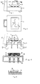
- Figures 1-3 of the accompanying drawings illustrate schematically a co-ordinate measuring machine of the aforedescribed kind with an object 1 to be measured placed on a laying-up table 2, which is supported by feet 3 resting on a base 4.
- a column 5 which carries those elements and movement means that are needed to move the probe 6 in three directions at right angles to one another is attached to the base 4.
- the base 4 is supported by feet 7.
- Figure 2 is a partly sectioned view of the machine shown in Figure 1 taken from above, and shows the feet 3 of the laying-up table positioned in the corners of an imaginary isosceles triangle.
- Figure 3 is a schematic highly exaggerated illustration of how the base 4 is deformed principly by an object 1 to be measured placed on the laying-up table 2. If it is assumed that the centre of gravity of the object coincides with the centre point of the imaginary isosceles triangle that can be drawn between the feet 3 of the laying-up table 2, the weight G of the object will be distributed equally between the feet 3 and the base will be subjected to a punctiform load G/3 at the location of the feet 3. The laying-up table 4 will therefore be subjected to a bending moment which will cause the table to bend in the manner highly exaggerated in Figure 3 with broken lines, therewith deforming the table and causing the column 5 attached to the table 4 to move out of its precisely vertical position.
- This movement of the column 5 is caused by the effect of the weight of the object lying on the laying-up table, its position on the table and the location of its centre of gravity. Deformation-bending of the laying-up table and subsequent movement of the column 5 from its precisely vertical position will therefore vary in dependence on where the object is placed on the table and on how the object is placed.
- the repetitive precision of the co-ordinate measuring machine i.e. control measurement to ascertain that a manufactured product coincides with a prototype, is therefore impaired by the bending deformation described above.
- each foot of the measuring table rests in a respective hemispherical cup mounted on the base.
- Figures 4 and 6 illustrate a preferred embodiment of the base 8 and the laying-up table 9 of an inventive co-ordinate measuring machine.
- the column or columns which carries or carry the actual measuring equipment is/are not shown in the drawings, since such equipment forms no part of the invention.
- the conventional measuring machine illustrated in Figures 1-3 merely constitutes a non-limiting example of a measuring machine to which the invention can be applied, and that in principle the invention can be applied to all co-ordinate measuring machines with which the object to be measured is placed on a laying-up table which rests on the machine base.
- the laying-up table has three feet 10 which are arranged in the same manner as the feet 3 of the machine illustrated in Figures 1-3, i.e. in the comers of an imaginary isosceles triangle.
- the feet 10 of the laying-up table 9 have hemispherical surfaces which face towards the base 8 and rest in bearing cups 11 mounted on the upper surface of the base.
- the base 8 is provided with feet 12 which are located immediately beneath the feet 10 on the laying-up table.
- Figure 5 illustrates schematically and in an exaggerated fashion how the laying-up table 2 of the conventional co-ordinate measuring machine illustrated in Figures 1-3 is deformed when subjected to the load of an object to be measured.
- the contact points between the feet of the table 2 and the base 4 are moved, and therewith also the attack points of the force vectors, due to deformation of the table.
- Such movement of the contact points creates a moment arm for the force vector through the table feet of corresponding size and there occurs a bending moment which can deform the base.
- the feet of the table 10 In order to ensure that bending deformation of the laying-up table will not cause the contact points between the feet 10 of the table 9 and the upper surface of the base 8 to move, the feet of the table 10 have a hemispherical shape on the side thereof proximal to the base. Consequently, the attack point of the force vectors through the table feet will always lie on the same place centrally above the centre point of the base feet and the base will not be subjected to bending moments as a result of deformation of the table. In order to distribute the load over a wide surface area, the feet 10 of the table 9 preferably rest in bearing cups 11 mounted on the upper surface of the base 8.
- bearing cups 11 are conveniently attached to the base 8 in a manner to indicate how the laying-up table shall be placed on the base and to ensure that the laying-up table is correctly positioned.
- more than three feet may be provided, e.g. so as to distribute the load on more points or to increase the stability tilt of the laying-up table.
- the table feet may be placed directly on the base, the position of the base feet being marked in some other way than by means of bearing cups, for instance by markings made on the upper side of the base.
- the feet of the laying-up table have spherical surfaces, since the bending moment that results from the contact points of the feet because of table deformation is so small that the requisite accuracy can often be maintained.
- the invention is therefore only limited by the contents of the following Claims.
Landscapes
- Physics & Mathematics (AREA)
- General Physics & Mathematics (AREA)
- A Measuring Device Byusing Mechanical Method (AREA)
- Length Measuring Devices With Unspecified Measuring Means (AREA)
Description
- The present invention relates to a co-ordinate measuring machine which includes a base, base-carried measuring equipment, and a measuring table on which the object to be measured is placed.
- Co-ordinate measuring machines are used to establish the co-ordinates of numerous points on the surface of an object with extreme accuracy, so as to determine the appearance of the article being measured. For instance, a co-ordinate measuring machine can be used to measure the co-ordinates of a prototype and the measurement values obtained then used to control a machine tool in the manufacture an object whose shape is identical to the measured object. In order to meet the measuring accuracy required, co-ordinate measuring machines are normally constructed with great stability so as to prevent deformation in the machine, since deformation is liable to have a negative effect on the measuring result.
- WO 89/03505 discloses a coordinate measuring machine in which the work table is supported on the base by blocks slidably supported on the base. This arrangement is said to isolate the work table and the base against both differential expansion and contraction and deflection caused by workpiece weight.
- GB-A-2 080 954 describes a co-ordinate measuring machine which comprises a rigded base frame providing respective sleeves disposed at intersections of ribs, each sleeve receiving therewithin a respective vertically extending support whose lower end bears on the ground and whose upper end acts as a support for a measuring table by way of a respective bearing element. The table is located but not supported by the base frame by way of coupling elements in a manner free from play and stress, which elements may include an annular diaphragm disposed between the upper end of each support and the frame. Alternatively, the coupling elements can comprise a ball and a pin attached to the underside of the table and associated respectively with a ball socket and slotted guide carried by the frame.
- The present invention is intended to avoid deformation of the machine base or machine stand as a result of bending loads caused by the laying-up table, this object applying to all types of co-ordinate measuring machines which comprise a base or stand which supports a laying-up table on which the object to be measured is placed and to which the column or columns carrying the measuring probe of the machine are attached.
- This problem is illustrated in Figures 1-3 of the accompanying drawings, these Figures illustrating schematically a co-ordinate measuring machine of the aforedescribed kind with an object 1 to be measured placed on a laying-up table 2, which is supported by
feet 3 resting on a base 4. Acolumn 5 which carries those elements and movement means that are needed to move the probe 6 in three directions at right angles to one another is attached to the base 4. The base 4 is supported byfeet 7. Figure 2 is a partly sectioned view of the machine shown in Figure 1 taken from above, and shows thefeet 3 of the laying-up table positioned in the corners of an imaginary isosceles triangle. - Figure 3 is a schematic highly exaggerated illustration of how the base 4 is deformed principly by an object 1 to be measured placed on the laying-up table 2. If it is assumed that the centre of gravity of the object coincides with the centre point of the imaginary isosceles triangle that can be drawn between the
feet 3 of the laying-up table 2, the weight G of the object will be distributed equally between thefeet 3 and the base will be subjected to a punctiform load G/3 at the location of thefeet 3. The laying-up table 4 will therefore be subjected to a bending moment which will cause the table to bend in the manner highly exaggerated in Figure 3 with broken lines, therewith deforming the table and causing thecolumn 5 attached to the table 4 to move out of its precisely vertical position. - This movement of the
column 5 is caused by the effect of the weight of the object lying on the laying-up table, its position on the table and the location of its centre of gravity. Deformation-bending of the laying-up table and subsequent movement of thecolumn 5 from its precisely vertical position will therefore vary in dependence on where the object is placed on the table and on how the object is placed. The repetitive precision of the co-ordinate measuring machine, i.e. control measurement to ascertain that a manufactured product coincides with a prototype, is therefore impaired by the bending deformation described above. Any deformation in the laying-up table on the other hand will have only an insignificant effect, since each measuring operation carried out with the measuring probe 6 presumes that the object to be measured has been pre-aligned or set-up within the operational volume of the machine prior to carrying out the actual measuring operation. - The aforesaid problems are solved in accordance with the invention by means of a measuring machine as defined in claim 1. This ensures that the force vectors from the table feet will pass through the base feet irrespective of any deformation in the laying-up table.
- According to a preferred embodiment of an inventive co-ordinate measuring machine, each foot of the measuring table rests in a respective hemispherical cup mounted on the base.
- A preferred embodiment of the invention will now be described with reference to the accompanying drawings, in which
- Figures 1-3 are respectively a side view of a conventional co-ordinate measuring machine, a schematic sectional view taken on the line II-II in Figure 1, and a partial side view respectively, these views having been described in the aforegoing with the intention of illustrating the problems solved by the invention;
- Figure 4 is a vertical sectional view of a base and a laying-up table of a co-ordinate measuring machine according to one preferred embodiment of the invention;
- Figure 5 is a side view of a conventional laying-up table and shows the table deformed by the weight of the object to be measured in a highly exaggerated fashion; and
- Figure 6 is a side view of a bearing cup for one foot of a laying-up table of an inventive co-ordinate measuring machine.
-
- Figures 4 and 6 illustrate a preferred embodiment of the base 8 and the laying-up table 9 of an inventive co-ordinate measuring machine. The column or columns which carries or carry the actual measuring equipment is/are not shown in the drawings, since such equipment forms no part of the invention. It should be pointed out that the conventional measuring machine illustrated in Figures 1-3 merely constitutes a non-limiting example of a measuring machine to which the invention can be applied, and that in principle the invention can be applied to all co-ordinate measuring machines with which the object to be measured is placed on a laying-up table which rests on the machine base.
- In the embodiment illustrated in Figure 4, the laying-up table has three
feet 10 which are arranged in the same manner as thefeet 3 of the machine illustrated in Figures 1-3, i.e. in the comers of an imaginary isosceles triangle. Thefeet 10 of the laying-up table 9 have hemispherical surfaces which face towards the base 8 and rest inbearing cups 11 mounted on the upper surface of the base. The base 8 is provided withfeet 12 which are located immediately beneath thefeet 10 on the laying-up table. Because thefeet - Figure 5 illustrates schematically and in an exaggerated fashion how the laying-up table 2 of the conventional co-ordinate measuring machine illustrated in Figures 1-3 is deformed when subjected to the load of an object to be measured. As illustrated in the Figure, the contact points between the feet of the table 2 and the base 4 are moved, and therewith also the attack points of the force vectors, due to deformation of the table. Such movement of the contact points creates a moment arm for the force vector through the table feet of corresponding size and there occurs a bending moment which can deform the base. In order to ensure that bending deformation of the laying-up table will not cause the contact points between the
feet 10 of the table 9 and the upper surface of the base 8 to move, the feet of the table 10 have a hemispherical shape on the side thereof proximal to the base. Consequently, the attack point of the force vectors through the table feet will always lie on the same place centrally above the centre point of the base feet and the base will not be subjected to bending moments as a result of deformation of the table. In order to distribute the load over a wide surface area, thefeet 10 of the table 9 preferably rest inbearing cups 11 mounted on the upper surface of the base 8. Thesebearing cups 11 are conveniently attached to the base 8 in a manner to indicate how the laying-up table shall be placed on the base and to ensure that the laying-up table is correctly positioned. However, it is necessary that at least two of these connections between thecups 11 and the base are resilient, so as to enable the cups to move so as to compensate for thermal expansion and tolerance errors. - It will be understood that the invention is not restricted to the described and illustrated embodiment thereof and that modifications are possible within the scope of the invention. For instance, more than three feet may be provided, e.g. so as to distribute the load on more points or to increase the stability tilt of the laying-up table. Furthermore, the table feet may be placed directly on the base, the position of the base feet being marked in some other way than by means of bearing cups, for instance by markings made on the upper side of the base. Neither need the feet of the laying-up table have spherical surfaces, since the bending moment that results from the contact points of the feet because of table deformation is so small that the requisite accuracy can often be maintained. The invention is therefore only limited by the contents of the following Claims.
Claims (2)
- A co-ordinate measuring machine comprising a base (8), base-carried measuring equipment, and a measuring table (9) on which the object to be measured is placed, the measuring table (9) including at least three feet (10) through which the measuring table rests on the base (8) and wherein the base includes the same number of feet (12) as the measuring table through which the base rests on an underlying supportive surface,
characterised in that each of said feet is
placed directly beneath a corresponding foot (10) of the measuring table that each of the feet (10) of the measuring table has a spherical surface proximal to the base (8) so that the attack point of force vectors through the table feet will lie above the centre point of the base feet (12). - A machine according to Claim 2, characterised in that the spherical surface of the measuring table feet (10) rest in hemispherical cups (11) arranged on the base (8).
Applications Claiming Priority (2)
| Application Number | Priority Date | Filing Date | Title |
|---|---|---|---|
| SE9203884 | 1992-12-22 | ||
| SE9203884A SE470223B (en) | 1992-12-22 | 1992-12-22 | Coordinate |
Publications (3)
| Publication Number | Publication Date |
|---|---|
| EP0604380A1 EP0604380A1 (en) | 1994-06-29 |
| EP0604380B1 EP0604380B1 (en) | 1997-04-02 |
| EP0604380B2 true EP0604380B2 (en) | 2001-03-07 |
Family
ID=20388229
Family Applications (1)
| Application Number | Title | Priority Date | Filing Date |
|---|---|---|---|
| EP93850241A Expired - Lifetime EP0604380B2 (en) | 1992-12-22 | 1993-12-22 | A co-ordinate measuring machine |
Country Status (3)
| Country | Link |
|---|---|
| EP (1) | EP0604380B2 (en) |
| DE (1) | DE69309418T3 (en) |
| SE (1) | SE470223B (en) |
Cited By (1)
| Publication number | Priority date | Publication date | Assignee | Title |
|---|---|---|---|---|
| US7698829B2 (en) | 2005-12-02 | 2010-04-20 | Carl Zeiss Industrielle Messtechnik Gmbh | Device for determining a measureable variable on a measurement object |
Families Citing this family (1)
| Publication number | Priority date | Publication date | Assignee | Title |
|---|---|---|---|---|
| DE19858428C2 (en) * | 1998-12-17 | 2002-09-12 | Leica Microsystems | Coordinate-measuring arrangement |
Family Cites Families (5)
| Publication number | Priority date | Publication date | Assignee | Title |
|---|---|---|---|---|
| DD152409A1 (en) * | 1980-07-31 | 1981-11-25 | Horst Donat | DEVICE FOR COUPLING A MEASURING TABLE TO THE BASE OF A MEASURING MACHINE |
| US4495703A (en) * | 1981-11-25 | 1985-01-29 | Mitutoyo Mfg. Co., Ltd. | Coordinate measuring instrument |
| DE3690033C2 (en) * | 1985-01-22 | 1992-09-03 | Mitutoyo Mfg Co Ltd | Coordinate measuring instrument |
| US4594791A (en) * | 1985-01-24 | 1986-06-17 | The Warner & Swasey Company | Bridge type coordinate measuring machine |
| US4763420A (en) * | 1987-10-06 | 1988-08-16 | Brown & Sharpe Manufacturing Company | Base assembly for coordinate measuring machine |
-
1992
- 1992-12-22 SE SE9203884A patent/SE470223B/en not_active IP Right Cessation
-
1993
- 1993-12-22 DE DE1993609418 patent/DE69309418T3/en not_active Expired - Lifetime
- 1993-12-22 EP EP93850241A patent/EP0604380B2/en not_active Expired - Lifetime
Non-Patent Citations (2)
| Title |
|---|
| Prospectus on high gloss paper of the Carl Zeiss company "CNC Corrdinate Measuring Machines with Universal 3D Probe Head", printed 1987 † |
| Prospectus on high gloss paper of the Carl Zeiss company "CNC Koordinatenmeßgeräte Portalmeßgeräte mit messendem Tastkopf, printed 1989 † |
Cited By (1)
| Publication number | Priority date | Publication date | Assignee | Title |
|---|---|---|---|---|
| US7698829B2 (en) | 2005-12-02 | 2010-04-20 | Carl Zeiss Industrielle Messtechnik Gmbh | Device for determining a measureable variable on a measurement object |
Also Published As
| Publication number | Publication date |
|---|---|
| SE9203884L (en) | 1993-12-06 |
| DE69309418T3 (en) | 2001-06-28 |
| DE69309418T2 (en) | 1997-10-09 |
| DE69309418D1 (en) | 1997-05-07 |
| SE9203884D0 (en) | 1992-12-22 |
| EP0604380A1 (en) | 1994-06-29 |
| SE470223B (en) | 1993-12-06 |
| EP0604380B1 (en) | 1997-04-02 |
Similar Documents
| Publication | Publication Date | Title |
|---|---|---|
| US4177568A (en) | Measurement head | |
| US4854050A (en) | Contact-sensing probe | |
| EP0470234B1 (en) | Contact probes | |
| US3869799A (en) | Universal multi-coordinate sensor | |
| US4454770A (en) | Torque-insensitive load cell | |
| US20010045825A1 (en) | Position measuring device for detecting displacements with at least three degrees of freedom | |
| WO1989003505A1 (en) | Base assembly for coordinate measuring machine | |
| WO1985005176A1 (en) | Improvement relating to coordinate positioning apparatus | |
| JPH0295229A (en) | Measuring base | |
| US4621533A (en) | Tactile load sensing transducer | |
| JP7126181B2 (en) | FOOT STRUCTURE OF LEGED MOBILE ROBOT, AND LEGED MOBILE ROBOT | |
| EP1584894B1 (en) | Mount table, surface texture measuring machine and surface texture measuring method | |
| JPS59180418A (en) | Measuring arm of multiple coordinate measuring device | |
| EP0604380B2 (en) | A co-ordinate measuring machine | |
| JP2767766B2 (en) | 6-axis force sensor | |
| JPH0127364B2 (en) | ||
| JPH04116744U (en) | Stress measuring device and tactile screen that constitutes it | |
| CN111805302A (en) | Machine tool leveling device and leveling method | |
| JPH04283638A (en) | Apparatus for measuring center of gravity | |
| JP2711429B2 (en) | Thrust test equipment | |
| GB2080954A (en) | Attaching a measuring table to the base frame of a coordinate measuring machine | |
| JP3288906B2 (en) | Spherical shape constant pressure measuring device | |
| JP2760470B2 (en) | Floor reaction force meter | |
| KR100235683B1 (en) | Force / moment sensor | |
| JPH0366540A (en) | Work positioning method with locating pin |
Legal Events
| Date | Code | Title | Description |
|---|---|---|---|
| PUAI | Public reference made under article 153(3) epc to a published international application that has entered the european phase |
Free format text: ORIGINAL CODE: 0009012 |
|
| AK | Designated contracting states |
Kind code of ref document: A1 Designated state(s): DE FR GB IT |
|
| 17P | Request for examination filed |
Effective date: 19941130 |
|
| 17Q | First examination report despatched |
Effective date: 19960402 |
|
| GRAG | Despatch of communication of intention to grant |
Free format text: ORIGINAL CODE: EPIDOS AGRA |
|
| GRAH | Despatch of communication of intention to grant a patent |
Free format text: ORIGINAL CODE: EPIDOS IGRA |
|
| GRAH | Despatch of communication of intention to grant a patent |
Free format text: ORIGINAL CODE: EPIDOS IGRA |
|
| GRAA | (expected) grant |
Free format text: ORIGINAL CODE: 0009210 |
|
| ITF | It: translation for a ep patent filed | ||
| AK | Designated contracting states |
Kind code of ref document: B1 Designated state(s): DE FR GB IT |
|
| ET | Fr: translation filed | ||
| REF | Corresponds to: |
Ref document number: 69309418 Country of ref document: DE Date of ref document: 19970507 |
|
| PLBI | Opposition filed |
Free format text: ORIGINAL CODE: 0009260 |
|
| 26 | Opposition filed |
Opponent name: FIRMA CARL ZEISS Effective date: 19971121 |
|
| PLBF | Reply of patent proprietor to notice(s) of opposition |
Free format text: ORIGINAL CODE: EPIDOS OBSO |
|
| PLBF | Reply of patent proprietor to notice(s) of opposition |
Free format text: ORIGINAL CODE: EPIDOS OBSO |
|
| PLAW | Interlocutory decision in opposition |
Free format text: ORIGINAL CODE: EPIDOS IDOP |
|
| PLAW | Interlocutory decision in opposition |
Free format text: ORIGINAL CODE: EPIDOS IDOP |
|
| PUAH | Patent maintained in amended form |
Free format text: ORIGINAL CODE: 0009272 |
|
| STAA | Information on the status of an ep patent application or granted ep patent |
Free format text: STATUS: PATENT MAINTAINED AS AMENDED |
|
| 27A | Patent maintained in amended form |
Effective date: 20010307 |
|
| AK | Designated contracting states |
Kind code of ref document: B2 Designated state(s): DE FR GB IT |
|
| ET3 | Fr: translation filed ** decision concerning opposition | ||
| ITF | It: translation for a ep patent filed | ||
| REG | Reference to a national code |
Ref country code: GB Ref legal event code: IF02 |
|
| PGFP | Annual fee paid to national office [announced via postgrant information from national office to epo] |
Ref country code: GB Payment date: 20121220 Year of fee payment: 20 Ref country code: IT Payment date: 20121217 Year of fee payment: 20 |
|
| PGFP | Annual fee paid to national office [announced via postgrant information from national office to epo] |
Ref country code: FR Payment date: 20130123 Year of fee payment: 20 Ref country code: DE Payment date: 20121219 Year of fee payment: 20 |
|
| REG | Reference to a national code |
Ref country code: DE Ref legal event code: R071 Ref document number: 69309418 Country of ref document: DE |
|
| REG | Reference to a national code |
Ref country code: GB Ref legal event code: PE20 Expiry date: 20131221 |
|
| PG25 | Lapsed in a contracting state [announced via postgrant information from national office to epo] |
Ref country code: GB Free format text: LAPSE BECAUSE OF EXPIRATION OF PROTECTION Effective date: 20131221 Ref country code: DE Free format text: LAPSE BECAUSE OF EXPIRATION OF PROTECTION Effective date: 20131224 |