EP0604251B1 - Driving device for the backlash compensation of a drum brake - Google Patents
Driving device for the backlash compensation of a drum brake Download PDFInfo
- Publication number
- EP0604251B1 EP0604251B1 EP19930402855 EP93402855A EP0604251B1 EP 0604251 B1 EP0604251 B1 EP 0604251B1 EP 19930402855 EP19930402855 EP 19930402855 EP 93402855 A EP93402855 A EP 93402855A EP 0604251 B1 EP0604251 B1 EP 0604251B1
- Authority
- EP
- European Patent Office
- Prior art keywords
- cable
- guide
- disc
- pin
- winding
- Prior art date
- Legal status (The legal status is an assumption and is not a legal conclusion. Google has not performed a legal analysis and makes no representation as to the accuracy of the status listed.)
- Expired - Lifetime
Links
Images


Classifications
-
- F—MECHANICAL ENGINEERING; LIGHTING; HEATING; WEAPONS; BLASTING
- F16—ENGINEERING ELEMENTS AND UNITS; GENERAL MEASURES FOR PRODUCING AND MAINTAINING EFFECTIVE FUNCTIONING OF MACHINES OR INSTALLATIONS; THERMAL INSULATION IN GENERAL
- F16D—COUPLINGS FOR TRANSMITTING ROTATION; CLUTCHES; BRAKES
- F16D65/00—Parts or details
- F16D65/38—Slack adjusters
- F16D65/40—Slack adjusters mechanical
- F16D65/52—Slack adjusters mechanical self-acting in one direction for adjusting excessive play
- F16D65/56—Slack adjusters mechanical self-acting in one direction for adjusting excessive play with screw-thread and nut
- F16D65/561—Slack adjusters mechanical self-acting in one direction for adjusting excessive play with screw-thread and nut for mounting within the confines of a drum brake
- F16D65/565—Slack adjusters mechanical self-acting in one direction for adjusting excessive play with screw-thread and nut for mounting within the confines of a drum brake arranged diametrically opposite to service brake actuator, and subjected to service brake force
Description
La présente invention concerne un dispositif de commande d'un dispositif de rattrapage de jeu pour frein à tambour.The present invention relates to a device for controlling a backlash device for a drum brake.
De façon classique, un frein à tambour pour véhicule automobile comprend un tambour, solidaire d'une roue du véhicule, et un plateau, solidaire d'un essieu du véhicule, formant support pour deux mâchoires munies de garnitures destinées à coopérer par frottement avec la surface interne du tambour lorsque le frein est actionné.Conventionally, a drum brake for a motor vehicle comprises a drum, integral with a vehicle wheel, and a plate, integral with an axle of the vehicle, forming a support for two jaws provided with linings intended to cooperate by friction with the internal surface of the drum when the brake is applied.
Lorsque le frein est au repos, il existe un jeu entre les garnitures des mâchoires et la surface interne de frottement du tambour.When the brake is at rest, there is a clearance between the linings of the shoes and the internal friction surface of the drum.
Ce jeu ayant tendance à augmenter à mesure que l'usure des garnitures s'accentue, il est connu d'équiper le frein à tambour d'un dispositif de rattrapage de jeu.This play tends to increase as the wear on the linings increases, it is known to equip the drum brake with a play take-up device.
On connaît déjà dans l'état de la technique un dispositif de commande d'un dispositif de rattrapage de jeu pour frein à tambour, du type comprenant un levier d'actionnement du dispositif de rattrapage de jeu, porté par une première mâchoire du frein, un câble relié par une première extrémité à ce levier et par une seconde extrémité à la seconde mâchoire du frein, et un organe de renvoi du câble porté par la première mâchoire.A device for controlling a play take-up device for a drum brake is already known in the prior art, of the type comprising an actuating lever for the play take-up device, carried by a first brake shoe, a cable connected by a first end to this lever and by a second end to the second brake shoe, and a cable return member carried by the first shoe.
Un tel dispositif de commande est décrit par exemple dans US-3 184 008.Such a control device is described for example in US-3,184,008.
De façon classique, le levier d'actionnement comprend des moyens élastiques de rappel en position de repos permettant de maintenir le câble tendu.Conventionally, the actuating lever comprises elastic means for returning to the rest position making it possible to keep the cable taut.
L'invention a pour but le réglage précis de la position initiale du levier et de la tension initiale du câble, ceci avec des moyens simples et faciles à mettre en oeuvre.The invention aims to precisely adjust the initial position of the lever and the initial tension of the cable, this with simple and easy to implement means.
A cet effet l'invention a pour objet un dispositif de commande d'un dispositif de rattrapage de jeu pour frein à tambour, du type précité, caractérisé en ce que l'organe de renvoi est accroché sur la première mâchoire par emboîtement d'un plot, porté par l'un de ces deux éléments, dans un orifice complémentaire, ménagé dans l'autre de ces deux éléments, le plot et l'orifice complémentaire comportant des moyens de positionnement angulaire relatif, l'organe de renvoi comportant un guide courbe d'enroulement du câble, de centre de courbure excentré par rapport à l'axe du plot ou de l'orifice complémentaire, de manière que la tension du câble soit fonction de la position angulaire du plot dans l'orifice complémentaire.To this end, the subject of the invention is a device for controlling a play take-up device for a drum brake, of the aforementioned type, characterized in that the return member is hooked on the first jaw by fitting a stud, carried by one of these two elements, in a complementary orifice, formed in the other of these two elements, the stud and the complementary orifice comprising relative angular positioning means, the return member comprising a curved guide for winding the cable, of center curvature eccentric with respect to the axis of the stud or of the complementary hole, so that the cable tension is a function of the angular position of the stud in the complementary hole.
Suivant d'autres caractéristiques de l'invention:
- les moyens de positionnement angulaire relatif comportent des surfaces cannelées complémentaires délimitant respectivement les contours du plot et de l'orifice complémentaire ;
- le plot d'accrochage est porté par l'organe de renvoi ;
- l'organe de renvoi comporte un disque, d'axe excentré par rapport à l'axe du plot ou de l'orifice complémentaire, le guide d'enroulement du câble s'étendant autour du contour de ce disque.
- the relative angular positioning means comprise complementary grooved surfaces respectively delimiting the contours of the stud and of the complementary orifice;
- the attachment stud is carried by the return member;
- the return member comprises a disc, with an axis eccentric with respect to the axis of the stud or of the complementary orifice, the cable winding guide extending around the contour of this disc.
Suivant différents modes de réalisation de l'organe de renvoi du câble :
- le disque est solidaire du plot ;
- l'organe de renvoi comporte un support, solidaire du plot, le disque étant monté à rotation sur ce support ;
- le guide d'enroulement du câble est délimité par une gorge annulaire ménagée dans le contour du disque;
- le guide d'enroulement du câble est en appui sur une surface périphérique du disque, sous l'effet de la tension du câble, par l'intermédiaire d'un organe de liaison de forme complémentaire à cette surface périphérique d'appui, solidaire du guide ;
- le guide d'enroulement du câble est immobilisé en rotation par collage de l'organe de liaison sur la surface périphérique d'appui, après fixation de l'organe de renvoi sur la première mâchoire ;
- le guide d'enroulement du câble comporte une saillie destinée à être emboîtée dans un évidement d'immobilisation en rotation du guide, ménagé dans la première mâchoire ;
- la face opposée au plot du disque comporte des surfaces d'accrochage d'un outil de positionnement de l'organe de renvoi.
- the disc is integral with the stud;
- the return member comprises a support, integral with the stud, the disc being rotatably mounted on this support;
- the cable winding guide is delimited by an annular groove formed in the contour of the disc;
- the cable winding guide is in abutment on a peripheral surface of the disc, under the effect of the tension of the cable, by means of a connecting member of a shape complementary to this peripheral bearing surface, integral with the guide;
- the cable winding guide is immobilized in rotation by bonding the connecting member to the peripheral support surface, after fixing the return member on the first jaw;
- the cable winding guide has a projection intended to be fitted into a rotationally immobilizing recess of the guide, formed in the first jaw;
- the face opposite the pad of the disc has attachment surfaces for a tool for positioning the return member.
Des exemples de réalisation de l'invention seront décrits ci-dessous en se référant aux dessins annexés dans lesquels :
- la figure 1 est une vue de face d'un frein à tambour comportant un dispositif, selon l'invention, de commande d'un dispositif de rattrapage de jeu ;
- la figure 2 est une vue à échelle agrandie, en perspective, d'un organe de renvoi du câble selon un premier mode de réalisation de l'invention ;
- la figure 3 est une vue en coupe, suivant un plan axial du plot d'accrochage, d'un organe de renvoi du câble selon un second mode de réalisation de l'invention;
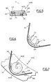
- la figure 4 est une vue de face d'un organe de renvoi du câble selon un troisième mode de réalisation de l'invention ;
- la figure 5 est une vue en coupe suivant la figure 5-5 de la figure 4 ;
- la figure 6 est une vue de face du guide d'enroulement du câble de l'organe de renvoi de la figure 4 ;
- la figure 7 est une vue similaire à la figure 4 d'un organe de renvoi du câble selon un quatrième mode de réalisation de l'invention.
- Figure 1 is a front view of a drum brake comprising a device, according to the invention, for controlling a play take-up device;
- Figure 2 is an enlarged perspective view of a cable return member according to a first embodiment of the invention;
- Figure 3 is a sectional view, along an axial plane of the attachment stud, of a cable return member according to a second embodiment of the invention;
- Figure 4 is a front view of a cable return member according to a third embodiment of the invention;
- Figure 5 is a sectional view along Figure 5-5 of Figure 4;
- Figure 6 is a front view of the cable winding guide of the return member of Figure 4;
- Figure 7 is a view similar to Figure 4 of a cable return member according to a fourth embodiment of the invention.
On a représenté à la figure 1 un frein à tambour pour véhicule automobile, désigné par la référence générale 10, comportant, de façon classique, un tambour 12, solidaire d'une roue du véhicule, et un plateau 14 solidaire d'un essieu du véhicule. Ce plateau 14 forme un support pour deux mâchoires 16,18 munies de garnitures 20,22 destinées à coopérer par frottement avec la surface interne 12I du tambour 12 lorsque le frein est actionné.FIG. 1 shows a drum brake for a motor vehicle, designated by the
Un cylindre 24 d'écartement des mâchoires 16,18, de type connu, est interposé entre deux extrémités 16A,18A en vis-à-vis des mâchoires 16,18.A
Un dispositif 26 de rattrapage de jeu est interposé entre les deux autres extrémités 16B,18B en vis-à-vis des mâchoires 16,18.A play take-up
De façon classique, ce dispositif 26 comprend une entretoise 28, de longueur variable, reliée par ses extrémités aux mâchoires 16,18, et une roue à rochet 30 de réglage de la longueur de l'entretoise 28, entraînée par un cliquet 32 porté par une lame-ressort 34. Cette lame 34 est fixée par une de ses extrémités à l'entretoise 28.Conventionally, this
Un ressort 36, relié par ses extrémités aux deux mâchoires 16,18, sollicite élastiquement ces dernières l'une vers l'autre.A
On a également représenté sur la figure 1, un dispositif 38, selon l'invention, de commande du dispositif de rattrapage de jeu 26.FIG. 1 also shows a
Ce dispositif 38 comporte un câble 40 relié par une première extrémité 40A à un levier 42 d'actionnement du dispositif 26 de rattrapage de jeu, articulé sur une première mâchoire 16, et par une seconde extrémité 40B à la seconde mâchoire 18.This
Un organe de renvoi 44, selon un premier mode de réalisation, est porté par la première mâchoire 16 et coopère avec la partie médiane du câble 40 de manière à former deux brins de câble sensiblement perpendiculaires.A
L'extrémité libre 42A du levier 42 est destinée à coopérer avec l'extrémité libre 34A de la lame-ressort 34 de manière à actionner le cliquet 32 d'entraînement de la roue à rochet 30 par déplacement du levier 42.The
La lame-ressort 34 permet d'une part de solliciter élastiquement le levier 42 vers une position de repos, et d'autre part de maintenir tendu le câble 40.The
En se référant à la figure 2, dans laquelle l'organe de renvoi 44 est montré plus en détail, on voit que ce dernier comporte un disque 46, d'axe X, muni d'une gorge annulaire 48, ménagée dans son contour, formant guide d'enroulement du câble 40.Referring to FIG. 2, in which the
L'organe de renvoi 44 comporte de plus un plot d'accrochage 50, solidaire du disque 46, d'axe Y excentré par rapport à l'axe X de ce disque 46.The
Le plot 50 est destiné à être emboîté dans un orifice complémentaire 52 ménagé dans la première mâchoire 16.The
Les contours du plot 50 et de l'orifice complémentaire 52 sont délimités respectivement par des surfaces complémentaires cannelées 50A,52A formant des moyens de positionnement angulaire relatif.The contours of the
L'extrémité libre du plot 50 est délimitée par une surface de centrage 54 facilitant le positionnement et l'emboîtement du plot 50 dans l'orifice complémentaire 52.The free end of the
On a également représenté sur la figure 2, un évidement 56, ménagé dans la face du disque 46 opposée au plot 50, délimitée par des surfaces d'accrochage d'un outil, de type connu, de positionnement de l'organe de renvoi 44 sur la mâchoire 16.Also shown in Figure 2, a
Le guide courbe 48 d'enroulement du câble 40 a un centre de courbure excentré par rapport à l'axe Y du plot de manière que la tension du câble est fonction de la position angulaire du plot 50 dans l'orifice complémentaire 52.The
Le réglage de la tension initiale du câble 40 et de la position initiale du levier 42 se fait de la façon suivante.The initial tension of the
Dans un premier temps, on place le plot 50 au droit de l'orifice 52 d'emboîtement, l'axe X du disque 46 étant disposé le plus près possible de l'axe R de rotation du tambour 12, cet axe R étant représenté par une croix sur la figure 1, puis on engage le câble 40 dans le guide courbe 48. Dans cette position de l'organe de renvoi 44, la tension du câble 40 est minimale.Firstly, the
Ensuite, on fait tourner l'organe de renvoi 44 autour de l'axe Y du plot 50, par exemple au moyen d'un outil accroché dans l'évidement 56, de manière à obtenir une tension du câble 40 adaptée pour le fonctionnement du dispositif 26 de rattrapage de jeu.Then, the
Lorsque la tension du câble 40 est réglée, on emboîte le plot 50 dans l'orifice complémentaire 52, ce plot 50 étant immobilisé en rotation par coopération des surfaces cannelées 50A,52A.When the tension of the
Sur la figure 3, on a représenté un organe 44A de renvoi de câble selon un second mode de réalisation.In Figure 3, there is shown a
Les éléments analogues à ceux de l'organe 44 de renvoi selon le premier mode de réalisation sont désignés par des références identiques.Elements similar to those of the
Dans ce cas, le disque 46A est monté à rotation autour d'un pivot 58 porté par un support 60 solidaire du plot 50. Par ailleurs, l'évidement 56 d'accrochage d'outil est ménagé dans l'extrémité libre du pivot 58.In this case, the
De préférence, un manchon 62, fabriqué dans un matériau de coefficient de frottement faible, est interposé entre le pivot 58 et le disque 46A.Preferably, a
La mise en place sur la mâchoire 16 de l'organe de renvoi 44A selon le second mode de réalisation se fait de façon analogue au premier mode de réalisation.The establishment on the
Sur les figures 4 et 5, on a représenté un organe 44B de renvoi de câble selon un troisième mode de réalisation.In Figures 4 and 5, there is shown a
Les éléments analogues à ceux des organes de renvoi précédemment décrits sont désignés par des références identiques.Elements similar to those of the previously described return members are designated by identical references.
Dans ce cas, le disque 46B est solidaire du plot d'accrochage 50.In this case, the
L'organe 44B de renvoi comporte de plus un guide 64 délimitant une gorge courbe 66 d'enroulement du câble 40, s'étendant autour du contour du disque 46B de manière que le centre de courbure de la gorge 66 soit excentré par rapport à l'axe Y du plot 50.The
Le guide 64 est en appui sur un décrochement 68 du contour du disque 46B, sous l'effet de la tension du câble 40, par l'intermédiaire d'un organe de liaison 70 de forme complémentaire, solidaire du guide 64.The
En se référant à la figure 6, sur laquelle l'organe de liaison 70 est représenté plus en détail, on voit que ce dernier comporte deux branches 72,74 délimitant entre elles une surface d'appui circulaire 76, de forme complémentaire au décrochement 68, s'étendant de préférence sur plus de 180°.Referring to Figure 6, in which the connecting
L'organe de liaison 70 est fixé sur le guide 64 par des moyens connus, par exemple par soudage ou par collage.The connecting
En se référant à nouveau à la figure 5, on voit que le guide 64 est immobilisé suivant l'axe X du disque 46B par emboîtement entre l'épaulement 80 formé par le décrochement 68 et la face 82 de la mâchoire 16 en regard de cet épaulement 80.Referring again to FIG. 5, it can be seen that the
L'immobilisation du guide 64 en rotation autour de l'axe X du disque 46B est assurée par l'adhérence des surfaces en appui mutuel du disque 46B et de l'organe de liaison 70. De préférence, l'organe de liaison 70 est collé sur le disque 46B après réglage de la position de l'organe de renvoi 44B et fixation de celui-ci sur la mâchoire 16.The immobilization of the
Le guide 64 d'enroulement de câble a un rayon de courbure supérieur à celui des précédents modes de réalisation ce qui permet de réduire la flexion du câble et d'obtenir un meilleur rendement des déplacements de ce câble.The
Par ailleurs, la mise en place sur la mâchoire 16 de l'organe de renvoi 44B se fait de façon analogue aux précédents modes de réalisation, après avoir interposé le guide 64 entre le câble 40 et le contour du disque 46B.Furthermore, the positioning on the
Sur la figure 7, on a représenté un organe 44C de renvoi de câble selon un quatrième mode de réalisation.In Figure 7, there is shown a
Dans ce cas, à la différence du troisième mode de réalisation, le guide 64A comporte une saillie 84 destinée à être emboîtée dans un évidement 86 d'immobilisation en rotation du guide, ménagé dans la mâchoire 16.In this case, unlike the third embodiment, the
Au cours du réglage de la tension du câble 40, le guide 64A est immobilisé en rotation par emboîtement de la saillie 84 dans l'évidement 86 alors que le disque 46B peut être déplacé en rotation pour régler l'excentricité de l'organe de renvoi 44C.During the adjustment of the tension of the
L'invention ne se limite pas aux modes de réalisation décrits.The invention is not limited to the embodiments described.
En particulier, l'organe de renvoi peut être accroché sur la mâchoire correspondante par emboîtement d'un plot solidaire de cette mâchoire dans un orifice complémentaire ménagé dans l'organe de renvoi.In particular, the return member can be hung on the corresponding jaw by fitting a stud secured to this jaw in a complementary orifice formed in the return member.
Par ailleurs, les surfaces cannelées de positionnement angulaire relatif du plot d'accrochage et de l'orifice complémentaire peuvent être remplacées par des surfaces moletées ou des moyens équivalents.Furthermore, the grooved surfaces of relative angular positioning of the attachment stud and of the complementary orifice can be replaced by knurled surfaces or equivalent means.
L'invention comporte de nombreux avantages.The invention has many advantages.
En particulier, elle permet de régler de façon simple et précise la position initiale du levier d'actionnement du dispositif de rattrapage de jeu ainsi que la tension initiale du câble de commande de ce levier.In particular, it allows the initial position of the actuation lever of the play take-up device to be adjusted simply and precisely, as well as the initial tension of the control cable of this lever.
Claims (11)
- A control device of a device (26) for clearance adjustment for a drum brake (12), of the kind comprising a lever (42) for operating the device (26) for clearance adjustment, and mounted on a first brake shoe (16), a cable (40) linked by a first end (40A) to this lever (42) and by a second end (40B) to the second brake shoe (18), and a returning member (44; 44A; 44B; 44C) of the cable (40) mounted on the first brake shoe (16), characterised in that the returning member (44; 44A; 44B; 44C) is engaged on the first brake shoe (16) by the encasement of a pin (50), mounted on one of these two members, in a complementary opening (52) formed in the second of these two members, the pin (50) and the complementary opening (52) comprising means (50A, 52A) for relative angular positioning, the returning member (44; 44A; 44B; 44C) comprising a curved guide (48; 64; 64A) - for winding the cable (40) - with a centre of curvature eccentric in relation to the axis (Y) of the pin (50) or of the complementary opening (52), in such a manner that the tension of the cable (40) depends on the angular position of the pin (50) in the complementary opening (52).
- A device according to Claim 1, characterised in that the means for relative angular positioning comprise complementary grooved surfaces (50A, 52A) bounding the outlines of the pin (50) and the complementary opening (52) respectively.
- A device according to Claim 1 or 2, characterised in that the engagement pin (50) is mounted on the returning member (44; 44A; 44B; 44C).
- A device according to any one of Claims 1 to 3, characterised in that the returning member (44; 44A; 44B; 44C) comprises a disc (46; 46A; 46B), of axis (X) eccentric in relation to the axis (Y) of the pin (50) or of the complementary opening (52), the guide (48; 64; 64A) for winding the cable extending around the outline of this disc (46; 46A; 46B).
- A device according to both Claims 3 and 4 taken together, characterised in that the disc (46; 46B) is integral with the pin (50).
- A device according to both Claims 3 and 4 taken together, characterised in that the returning member (44A) comprises a support (60), integral with the pin (50), the disc (46A) being mounted so as to rotate on this support (60).
- A device according to any one of Claims 4 to 6, characterised in that the guide for winding the cable is bounded by an annular groove (48) formed in the outline of the disc (46; 46A).
- A device according to Claim 5, characterised in that the guide (64; 64A) for winding the cable is supported on a peripheral surface (68) of the disc (46B), under the action of the tension of the cable (40), by way of a linking member (70), complementary in shape to this peripheral support surface (68), integral with the guide (64; 64A).
- A device according to Claim 8, characterised in that the guide (64) for winding the cable is immobilised in rotation by adhesion of the linking member (70) on the peripheral support surface (68), after fixing the returning member (44B) to the first brake shoe (16).
- A device according to Claim 8, characterised in that the guide (64A) for winding the cable comprises a projection (84) for being encased in a recess (86) for immobilisation in rotation of the guide, which is formed in the first brake shoe (16).
- A device according to any one of Claims 4 to 10, characterised in that the surface opposite the pin (50) of the disc (46; 46A; 46B) comprises engagement surfaces (56) for a tool for positioning the returning member (44; 44A; 44B; 44C).
Applications Claiming Priority (2)
| Application Number | Priority Date | Filing Date | Title |
|---|---|---|---|
| FR9215645 | 1992-12-23 | ||
| FR9215645A FR2699629B1 (en) | 1992-12-23 | 1992-12-23 | Device for controlling a backlash device for a drum brake. |
Publications (2)
| Publication Number | Publication Date |
|---|---|
| EP0604251A1 EP0604251A1 (en) | 1994-06-29 |
| EP0604251B1 true EP0604251B1 (en) | 1997-03-05 |
Family
ID=9437058
Family Applications (1)
| Application Number | Title | Priority Date | Filing Date |
|---|---|---|---|
| EP19930402855 Expired - Lifetime EP0604251B1 (en) | 1992-12-23 | 1993-11-24 | Driving device for the backlash compensation of a drum brake |
Country Status (3)
| Country | Link |
|---|---|
| EP (1) | EP0604251B1 (en) |
| DE (1) | DE69308516T2 (en) |
| FR (1) | FR2699629B1 (en) |
Family Cites Families (2)
| Publication number | Priority date | Publication date | Assignee | Title |
|---|---|---|---|---|
| SE300361B (en) * | 1962-01-02 | 1968-04-22 | Bendix Corp | |
| US3184008A (en) * | 1963-05-15 | 1965-05-18 | Bendix Corp | Automatic adjuster for non-servo brake |
-
1992
- 1992-12-23 FR FR9215645A patent/FR2699629B1/en not_active Expired - Fee Related
-
1993
- 1993-11-24 EP EP19930402855 patent/EP0604251B1/en not_active Expired - Lifetime
- 1993-11-24 DE DE1993608516 patent/DE69308516T2/en not_active Expired - Fee Related
Also Published As
| Publication number | Publication date |
|---|---|
| EP0604251A1 (en) | 1994-06-29 |
| DE69308516D1 (en) | 1997-04-10 |
| FR2699629B1 (en) | 1995-03-24 |
| FR2699629A1 (en) | 1994-06-24 |
| DE69308516T2 (en) | 1997-07-17 |
Similar Documents
| Publication | Publication Date | Title |
|---|---|---|
| EP1565666B1 (en) | Drum brake and brake shoe for one such brake | |
| FR2701917A1 (en) | Device with two control members for a cycle derailleur | |
| EP0734496B1 (en) | Automatic adjusting strut for drum brake | |
| EP0604251B1 (en) | Driving device for the backlash compensation of a drum brake | |
| EP0486341B1 (en) | Mechanically actuated drum brake | |
| EP0069657B1 (en) | Drum brake | |
| FR2725485A1 (en) | FRICTION CLUTCH WITH WEAR COMPENSATION OF FRICTION LININGS | |
| EP0546927B1 (en) | Hand brake lever for a parking brake | |
| FR2492923A1 (en) | Wear compensation for car clutch - uses ratchet effect on declutching pedal with cable tensioning spring returning pedal towards clearance stop | |
| EP0077726B1 (en) | Drum brake and strut for such a brake | |
| EP0061961B1 (en) | Drum brake with automatic adjustment | |
| EP0146444B1 (en) | Fixing device for a brake strut provided with an automatic adjuster for a drum brake shoe | |
| EP0254629B1 (en) | Spring for a drum brake assembly | |
| EP0003452B1 (en) | Drum brake | |
| EP0439977B1 (en) | Wedge actuated disc brake | |
| FR2499188A1 (en) | DRUM BRAKE | |
| FR2497308A1 (en) | DRUM BRAKE WITH INTERNAL SEGMENTS | |
| FR2496802A1 (en) | DEVICE FOR SUPPORTING INNER JAW BRAKES WITH AUTOMATIC REVERSE MECHANISM FOR AN INERTIA BRAKE TRAILER | |
| EP0642634B1 (en) | Auxiliary drum brake device having advanced automatic clearance adjustment | |
| FR2938313A1 (en) | Drum brake mechanism for wheel of motor vehicle, has shoe fixed on jaw by using fastener, so that shoe is dismounted from mechanism without dismounting jaw, where jaw includes retaining device for retaining median part of fastener | |
| EP0044772B1 (en) | Disc brake with moving caliper | |
| EP0319358A1 (en) | Drum brake with automatic adjustment | |
| FR2723731A1 (en) | Tensioner for conveyor chain | |
| EP1326769A1 (en) | Motor vehicle hand brake | |
| WO1996019372A1 (en) | Rail vehicle brake device |
Legal Events
| Date | Code | Title | Description |
|---|---|---|---|
| PUAI | Public reference made under article 153(3) epc to a published international application that has entered the european phase |
Free format text: ORIGINAL CODE: 0009012 |
|
| AK | Designated contracting states |
Kind code of ref document: A1 Designated state(s): DE GB IT |
|
| 17P | Request for examination filed |
Effective date: 19941207 |
|
| 17Q | First examination report despatched |
Effective date: 19950906 |
|
| GRAG | Despatch of communication of intention to grant |
Free format text: ORIGINAL CODE: EPIDOS AGRA |
|
| GRAH | Despatch of communication of intention to grant a patent |
Free format text: ORIGINAL CODE: EPIDOS IGRA |
|
| GRAH | Despatch of communication of intention to grant a patent |
Free format text: ORIGINAL CODE: EPIDOS IGRA |
|
| GRAA | (expected) grant |
Free format text: ORIGINAL CODE: 0009210 |
|
| AK | Designated contracting states |
Kind code of ref document: B1 Designated state(s): DE GB IT |
|
| GBT | Gb: translation of ep patent filed (gb section 77(6)(a)/1977) |
Effective date: 19970317 |
|
| REF | Corresponds to: |
Ref document number: 69308516 Country of ref document: DE Date of ref document: 19970410 |
|
| ITF | It: translation for a ep patent filed |
Owner name: 0508;02MIFBUGNION S.P.A. |
|
| PLBE | No opposition filed within time limit |
Free format text: ORIGINAL CODE: 0009261 |
|
| STAA | Information on the status of an ep patent application or granted ep patent |
Free format text: STATUS: NO OPPOSITION FILED WITHIN TIME LIMIT |
|
| 26N | No opposition filed | ||
| PGFP | Annual fee paid to national office [announced via postgrant information from national office to epo] |
Ref country code: DE Payment date: 19981026 Year of fee payment: 6 |
|
| PGFP | Annual fee paid to national office [announced via postgrant information from national office to epo] |
Ref country code: GB Payment date: 19981117 Year of fee payment: 6 |
|
| PG25 | Lapsed in a contracting state [announced via postgrant information from national office to epo] |
Ref country code: GB Free format text: LAPSE BECAUSE OF NON-PAYMENT OF DUE FEES Effective date: 19991124 |
|
| GBPC | Gb: european patent ceased through non-payment of renewal fee |
Effective date: 19991124 |
|
| PG25 | Lapsed in a contracting state [announced via postgrant information from national office to epo] |
Ref country code: DE Free format text: LAPSE BECAUSE OF NON-PAYMENT OF DUE FEES Effective date: 20000901 |
|
| PG25 | Lapsed in a contracting state [announced via postgrant information from national office to epo] |
Ref country code: IT Free format text: LAPSE BECAUSE OF NON-PAYMENT OF DUE FEES;WARNING: LAPSES OF ITALIAN PATENTS WITH EFFECTIVE DATE BEFORE 2007 MAY HAVE OCCURRED AT ANY TIME BEFORE 2007. THE CORRECT EFFECTIVE DATE MAY BE DIFFERENT FROM THE ONE RECORDED. Effective date: 20051124 |