EP0604037B1 - Busbar protection method - Google Patents
Busbar protection method Download PDFInfo
- Publication number
- EP0604037B1 EP0604037B1 EP93309660A EP93309660A EP0604037B1 EP 0604037 B1 EP0604037 B1 EP 0604037B1 EP 93309660 A EP93309660 A EP 93309660A EP 93309660 A EP93309660 A EP 93309660A EP 0604037 B1 EP0604037 B1 EP 0604037B1
- Authority
- EP
- European Patent Office
- Prior art keywords
- busbar
- current
- line
- lines
- value
- Prior art date
- Legal status (The legal status is an assumption and is not a legal conclusion. Google has not performed a legal analysis and makes no representation as to the accuracy of the status listed.)
- Expired - Lifetime
Links
Images


Classifications
-
- G—PHYSICS
- G01—MEASURING; TESTING
- G01R—MEASURING ELECTRIC VARIABLES; MEASURING MAGNETIC VARIABLES
- G01R31/00—Arrangements for testing electric properties; Arrangements for locating electric faults; Arrangements for electrical testing characterised by what is being tested not provided for elsewhere
- G01R31/08—Locating faults in cables, transmission lines, or networks
-
- H—ELECTRICITY
- H02—GENERATION; CONVERSION OR DISTRIBUTION OF ELECTRIC POWER
- H02H—EMERGENCY PROTECTIVE CIRCUIT ARRANGEMENTS
- H02H7/00—Emergency protective circuit arrangements specially adapted for specific types of electric machines or apparatus or for sectionalised protection of cable or line systems, and effecting automatic switching in the event of an undesired change from normal working conditions
- H02H7/22—Emergency protective circuit arrangements specially adapted for specific types of electric machines or apparatus or for sectionalised protection of cable or line systems, and effecting automatic switching in the event of an undesired change from normal working conditions for distribution gear, e.g. bus-bar systems; for switching devices
Definitions
- the present invention relates to electrical and electronic circuitry, and particularly concerns a busbar protection method which, in order to protect a busbar, makes it possible to detect a fault on a busbar of a transmission and distribution system, and to localise the faulty point to a specific section of the busbar.
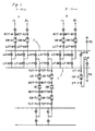
- FIG. 2 A part of a single line diagram in a conventional substation illustrating the high voltage side of the busbars in detail is seen in Figure 2.
- busbars X and Y There are two busbars X and Y, and interlink lines, which are configured to interlink both X and Y busbars.
- the transformers 1B and 2B as well as the transmission lines A and B are connected to the interlink lines and further to the X and Y busbars via line switches LX- and LY-, which serve to selectively connect the transformers and transmission lines to either of the X and Y busbars.
- the line switches LX- and LY- are generally called isolators.
- additional apparatus not illustrated in the Figure are also connected to the duplicated busbar in the same way.
- references in the Figure include the letter L to designate the line switch, the letters CB for the circuit breaker, the letters BCT for the current transformer of the line side, the letters LCT for the current transformer of the busbar side, the letters TCT for the current transformer of the transformer, the letter X for the X busbar, and the letter Y for the Y busbar.
- symbols following a hyphen designate the location where the apparatus is installed.
- omission of the characters following a hyphen such as the reference LX- designates generally the character of the apparatus and not the location where the apparatus is installed.
- the lines A-1L, A-2L, B-1L and B-2L as well as the transformers 1B and 2B are connected to the duplicated busbar via the circuit breakers CB-.
- the current transformers LCT- and BCT- are installed on both sides of the circuit breakers CB-.
- the current transformers LCT- connected to the busbar side serve to protect the lines or the apparatus such as transformers
- the current transformers BCT- connected to the line or the additional apparatus serve to protect the busbar.
- the current transformers LCT- and BCT- are collectively connected to the busbars, the lines or the additional apparatus.
- the current transformers which are installed near the busbar are designated as LCT-
- those connected to the apparatus are designated as BCT-.
- another interlink line which interlinks both of the busbars comprises a circuit breaker CB-B, the LX-B and LY-B as well as the CT-X and CT-Y.
- Lines such as transmission lines and apparatus such as transformers are connected in general to the duplicated busbar so as to equalise load on both of the busbars as far as possible. If the line 1L is connected to the X busbar, for instance as shown in the following Figure 3, then the line 2L is connected to the Y busbar. As a result, the current flowing through the circuit breaker CB-B which interlinks both of the busbars is nearly zero.
- the known protection method for the duplicated busbar system is as described in the following.
- Figure 3 illustrates the principle of a collective protection method of the duplicated busbar.
- all of the secondary circuits of the current transformers BCT- installed in the lines or in the apparatus such as transformers are connected in parallel and a detecting relay RY is also connected in parallel to the circuit thereof. Consequently, the sum total of the detected current of all of the current transformers BCT- flows through the relay RY.
- the relay RY is actuated, when the foregoing current flowing through the relay exceeds the predetermined threshold by means of which errors of the current transformer are taken into account.
- the fault on the duplicated busbar occurs on either side of the X busbar or the Y busbar, but in a few cases simultaneously on both sides of the two busbars. Accordingly, it is desirable to detect the fault and identify whether it is the X busbar or of the Y busbar is faulty.
- data from circuit elements is provided to a busbar protection device 1.
- the data comprises the current signals emanating from the current transformers BCT-, which are installed in the lines, apparatus etc; the current signals emanating from the current transformers BCT- interlinking the busbars; and the output signals indicating the switching state of the line switches LX- and LY-, i.e. "open” or "closed” signals.
- a digital processor 1 is built in the busbar protection device.
- the above mentioned input signals are sampled by the digital processing device with a certain period, and, on the basis of the data thereof, digital computing is then performed according to the following calculations.
- the inequality (1) is satisfied, i.e. if I is greater than the threshold value K, then this indicates that the fault has occurred on the X busbar.
- the inequality (2) indicates that the fault has occurred on the Y busbar
- the inequality (3) indicates that the fault has occurred somewhere on the busbars without the faulty busbar (the X busbar or the Y busbar) being identified.
- EP-A-0 400 230 describes a system for detecting a fault within a substation in which at least one input line and a plurality of busbar disconnecting switches are connected in circuit portions connecting the input line and output lines with each other.
- the system uses a plurality of optical current sensors to detect current flows in the lines and fault location detecting means using information from the current sensors to determine if a fault condition exists.
- the object of the present invention is to eliminate the foregoing problems associated with conventional busbar protection methods.
- a method of detecting and localising a fault in a busbar (X,Y) to which a plurality of lines or apparatus (A,B) is connected, on the basis of the currents detected by a current detector (BCT) installed in the busbar and respective ones installed in the lines or apparatus characterised in that said method comprises the steps of; a) computing a first value of current flowing at the junction of the line and the busbar using the current detected by the current detector installed in the busbar (CT); b) computing a second value of the current at the junction of the line and the busbar from the currents detected by the current detectors installed in the lines; c) calculating the difference of the first and second computed values; d) comparing the difference with a predetermined threshold value; and e) determining that a fault exists at the point if the difference exceeds the threshold value.
- CT current detector
- a second aspect of the present invention is characterised in a method of protecting a busbar, wherein, in protecting a busbar by judging whether a fault has occurred or not, on the basis of the current detected by the current detectors installed in the busbar and at least in two lines or apparatus connected thereto, a line or apparatus is designated as A, another line or apparatus is designated as B, a connection point of the line or apparatus A to the busbar is designated as A1 and a second connection point of the line or apparatus B to the busbar is designated as B1, and on the basis of the currents detected by the foregoing detectors, computing the difference of the current flowing out from the connection point A1 toward the connection point B1 and the current flowing into the connection point B1 from the direction of the connection point A1, it is consequently judged in particular that, if the foregoing current exceeds a predetermined value, the fault has occurred on the section between the connection points A1 and B1.
- a third aspect of the present invention is characterised in the method of protecting a busbar, wherein, in protecting a busbar by judging whether a fault has occurred or not, on the basis of the current detected by the current detectors installed in the busbar and at least two lines or apparatus connected thereto, a line or apparatus is designated as A, another line or apparatus neighbouring thereto is designated as B, a connection point of the line or apparatus A to the busbar is designated as A1 and a second connection point of the line or apparatus B to the busbar is designated as B1, and further the location of a current detector installed in the line or apparatus A is designated as A2, the current of the line A is computed from the currents detected by the current detectors excluding the current detector of the location A2, the difference of the current in line A and the current detected by the current detector of the location A2 is computed, the foregoing first current difference not exceeding a predetermined value, computing a second current difference between the current flowing out from the connection point A1 toward the connection point B1 and the current flowing into the
- the present invention is characterised in the method of protecting a busbar, wherein the busbar belongs to a duplicated busbar system to each busbar of which a line or apparatus is connected via a line switch, and it is possible to select for computing the current value of the current detectors according to the information on the switching state of the line switches, or wherein the busbar belongs to a single busbar system.
- the present invention is characterised in the method of protecting the duplicated busbar system, wherein designating two busbars as X busbar and Y busbar, designating a line or apparatus connected to the connection point S, to which the X busbar and the Y busbar are also connected via a line switch LX-A and a line switch LY-A respectively, as line or apparatus A, and then the line switch LX-A being closed and the line LY-A being open, computing the current flowing through the line switch LX-A from the current detected by the current detector, computing the difference of the above current and the current detected by the current detector installed in the line or apparatus A, it is consequently judged in particular that, if the foregoing current difference exceeds a predetermined value, the fault has occurred on the section between the connection point S and the line switch LY-A.
- the resulting fault current is expressed as an operational sum of the output current of each current transformer, that is, of the observable values.
- the current computed as the operational sum is zero in normal conditions where no fault occurs on the busbar, but, in the case of a fault, reaches a definite value other than zero. Noticing this point, it is possible to detect the fault, localising the faulty point to the specific section. If the currents of the first and second sections are zero, but the current sum exceeds a predetermined threshold, then it is judged that the fault has occurred on the end section of the busbar.
- the current i A1 in Figure 1 corresponds to the current IA1
- currents i A2 , i B , i B1 , i B2 , i T1 , i T2 also correspond to currents IA2, IB, etc, respectively.
- any type of current detector may be used including, but not limited to, the current transformer (CT).
- a fault which has occurred on either of the foregoing sections is collectively dealt with as the fault on the X busbar or on the Y busbar.
- the current i A1P is equal to zero, when no fault occurs. Accordingly, if the current i A1P is not zero, this indicates that the fault has occurred at the point P.
- the present invention sets a predetermined threshold K against the current i A1P at the point P, which is expressed as the operations of the observable values.
- i A1P > K it is judged that the fault has occurred on the section between the connection point of the line A-1L to the X busbar and the current transformer BCT-A1 by which the current i A1 is detected.
- this may be anywhere between the connection point to the busbar and the current transformer BCT-A1. This holds also between the connection point to the busbar and the current transformer BCT-A2, BCT-B1, BCT-B2, BCT-T1 and BCT-T2.
- the current i Q or i R is expressed as the operations of the observable values. This holds in other busbar sections between the neighbouring line outlets.
- This category is dealt with in the same way as one where a fault has occurred on the X busbar or the Y busbar. If a fault has occurred on the X busbar end, the currents, i A1P , i Q and i R of the points of the aforementioned categories (1) and (2) are nearly zero, and in addition, if the current i N of the following equation (9) exceeds a predetermined threshold, then it is considered that the fault has occurred on either of the busbar ends.
- i N i A1 + i T1 + i B1 + i B
- categories (1), (2) and (3) are described separately. However, it is a general practice to integrate these categories in order to detect the fault and to thus protect the busbar with the protecting relays.
- the present invention is described as for the case of duplicated busbars, but it is also applicable to the case of a single busbar or a ring busbar.
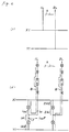
- Figure 5 is a connection diagram showing a part of the A-line 1L and 2L in Figure 2, and particularly relating to Figure 4.
- Figure 5a shows the part of the A-line 1L and 2L in Figure 4
- Figure 5b shows the portion of the A-line 1L and 2L.
- the section with the chained line B in Figure 5b is dealt with in Figure 4.
- the sections 1A1, 1A2, 2A1 and 2A2 are the ones to which the electric power is not supplied but the voltage is applied.
- the sections 1A2 and 2A2 can be dealt with collectively with the busbars connected thereto, and thus be included in category (2).
- the sections 1A1 and 2A1 are not included in the aforementioned category (2), and so the method proceeds as the following.
- the current i A1 F can be expressed in terms of some of the observable values i A1 , i A2 , i B1 , i B2 , i T1 , i T2 and i B and this indicates that the fault on the point F is included in the section 1A1.
- the current i 1A1 F is zero. If the current i 1A1 F is not zero, then it indicates that the fault has occurred on the point F, thus localising the fault to point F in the section 1A1.
- the present invention sets a predetermined value K1 for the current i 1A1 on the point F: i 1A1 > K1
- the present invention provides a more fine busbar protection method, which enables the faulty point to be localised to a specific section of the busbar, and is thus more efficient than the conventional one.
Description
Claims (6)
- A method of detecting and localising a fault in a busbar (X,Y) to which a plurality of lines or apparatus (A,B) are connected, on the basis of the currents detected by a current detector (CT) installed in the busbar and respective ones (BCT) installed in the lines or apparatus, characterised in that said method comprises the steps of;a) computing a first value of current flowing at the junction of the line and the busbar using the current detected by the current detector installed in the busbar;b) computing a second value of the current at the junction of the line and the busbar from the currents detected by the current detectors installed in the lines;c) calculating the difference of the first and second computed values;d) comparing the difference with a predetermined threshold value; ande) determining that a fault exists at the point if the difference exceeds the threshold value.
- The method according to claim 1, wherein a busbar has two lines (A,B) connected thereto, characterised in that a first value of current at a point on the busbar between the connection points of the lines (A,B) is computed from currents detected in the busbar and in one of the lines (A), and a second value of current at a point on the busbar between the connection points of the lines is computed from currents detected in the busbar and in the other lines (B), and in that if the difference exceeds the threshold value, a fault is determined to exist on the busbar between the connection points of the lines.
- The method according to claim 2, wherein;a) a first value of current at the junction of a first one of the lines and the busbar is computed from currents detected in the busbar and the second line, a second value of current at the junction of the first line and the busbar is computed from the current detected in the first line, the difference of the first and second computed values being compared to a threshold value;b) a third value of current at a point on the busbar between the connection points of the first and second lines is computed from currents detected in the busbar and the first line, a fourth value of current at a point on the busbar between the connection points of the first and second lines is computed from currents detected in the busbar and in the second line, the difference of the third and fourth computed values being compared to a threshold value;c) wherein if the differences do not exceed the threshold values, the operational sum of the currents flowing into or flowing out from the busbar excluding the end of the busbar is computed and compared with a predetermined limit value; andd) determining that, if the foregoing current sum exceeds the predetermined limit value, the fault has occurred on the end section of the busbar.
- The method according to any of the claims 1 to 3, wherein the busbar belongs to a duplicated busbar system to each busbar of which a line or apparatus is connected via a line switch; the method characterised in that the current detectors for computing the current value are selected according to information on the switching state of the line switches.
- The method according to any of the claims 1 to 4, wherein the busbar belongs to a single busbar system.
- The method according to claim 4, wherein a first (X) busbar and a second (Y) busbar are connected to a line (A) at a connection point (S), via a line switch LX-A and a line switch LY-A respectively, the line switch LX-A being closed and the line switch LY-A being open; characterised byfirstly computing the current flowing through the line switch LX-A from the current detected by the current detector;secondly computing the current difference between the current flowing through the line switch LX-A and the current detected by a current detector installed in the line or apparatus A;comparing the current difference with a predetermined value;and consequently judging in particular that, if the foregoing current difference exceeds a predetermined value, the fault has occurred on the section between the connection point S and the line switch LY-A.
Applications Claiming Priority (4)
| Application Number | Priority Date | Filing Date | Title |
|---|---|---|---|
| JP32556992 | 1992-12-04 | ||
| JP325569/92 | 1992-12-04 | ||
| JP99996/93 | 1993-04-27 | ||
| JP5099996A JPH06225448A (en) | 1992-12-04 | 1993-04-27 | Method of protecting bus |
Publications (2)
| Publication Number | Publication Date |
|---|---|
| EP0604037A1 EP0604037A1 (en) | 1994-06-29 |
| EP0604037B1 true EP0604037B1 (en) | 1998-07-08 |
Family
ID=26441084
Family Applications (1)
| Application Number | Title | Priority Date | Filing Date |
|---|---|---|---|
| EP93309660A Expired - Lifetime EP0604037B1 (en) | 1992-12-04 | 1993-12-02 | Busbar protection method |
Country Status (4)
| Country | Link |
|---|---|
| US (1) | US5566082A (en) |
| EP (1) | EP0604037B1 (en) |
| JP (1) | JPH06225448A (en) |
| DE (1) | DE69319561T2 (en) |
Families Citing this family (14)
| Publication number | Priority date | Publication date | Assignee | Title |
|---|---|---|---|---|
| US6249230B1 (en) * | 1999-03-18 | 2001-06-19 | Abb Power T&D Company Inc. | Ground fault location system and ground fault detector therefor |
| US7006085B1 (en) * | 2000-10-30 | 2006-02-28 | Magic Earth, Inc. | System and method for analyzing and imaging three-dimensional volume data sets |
| EP1223652A1 (en) * | 2001-01-16 | 2002-07-17 | Abb Research Ltd. | Method of locating a fault in a power supply network |
| US8804291B2 (en) | 2011-12-12 | 2014-08-12 | Utc Fire & Security Americas Corporation, Inc. | Line isolators for isolating multiple faults in emergency systems |
| GB2518188B (en) * | 2013-09-12 | 2020-11-18 | Ea Tech Limited | Fault level monitor |
| US9520254B2 (en) * | 2014-06-24 | 2016-12-13 | Eaton Corporation | Circuit interrupter including thermal trip assembly and printed circuit board Rogowski coil |
| CN106662608A (en) * | 2014-08-29 | 2017-05-10 | 西门子公司 | Method and device for determining fault direction of power transmission line |
| DE112018006983T5 (en) | 2018-01-31 | 2020-10-08 | Siemens Aktiengesellschaft | ERROR DETECTION METHOD AND ERROR DETECTION DEVICE FOR AN ELECTRICAL GRID WITH A DISTRIBUTED ENERGY SOURCE |
| JP7008551B2 (en) * | 2018-03-20 | 2022-01-25 | 三菱電機株式会社 | Failure determination device and protective relay device |
| DK3650871T3 (en) * | 2018-11-08 | 2024-02-26 | Nkt Hv Cables Ab | POWER CABLE MEASUREMENT SYSTEM |
| CN110707667B (en) * | 2019-09-10 | 2022-02-18 | 许继电气股份有限公司 | Direct-current line protection method and device for direct-current power distribution network |
| CN113030831B (en) * | 2021-03-10 | 2024-02-06 | 国网山西省电力公司检修分公司 | Method for quickly searching faults of voltage transformer in running state |
| CN113241844B (en) * | 2021-06-23 | 2022-06-14 | 广东电网有限责任公司 | 10kV bus sectional spare power automatic switching method and device |
| CN114465236B (en) * | 2022-04-11 | 2022-07-08 | 赫兹曼电力(广东)有限公司 | Self-healing method for power distribution network to cope with ground fault and power distribution network |
Family Cites Families (20)
| Publication number | Priority date | Publication date | Assignee | Title |
|---|---|---|---|---|
| US3771049A (en) * | 1971-01-05 | 1973-11-06 | Dossert Mfg Corp | Fault indicator and locator for buried cables and zero sequence current sensing device |
| CH577762A5 (en) * | 1974-02-27 | 1976-07-15 | Bbc Brown Boveri & Cie | |
| US4096539A (en) * | 1976-08-31 | 1978-06-20 | Scaturro Angelo J | Detector of backfeed electrical currents |
| JPS5829471B2 (en) * | 1978-10-30 | 1983-06-22 | 東京電力株式会社 | Accident point determination method |
| US4290013A (en) * | 1979-06-22 | 1981-09-15 | Genrad, Inc. | Method of and apparatus for electrical short testing and the like |
| FR2504331B1 (en) * | 1981-04-17 | 1989-12-08 | Prigent Hubert | CURRENT DETECTION DEVICE FOR LOCATING A RESISTIVE LOOP OR NOT IN A TWO-WIRE LINE OR FOR SWITCHING TWO TWO-WIRE LINES |
| DE3122109A1 (en) * | 1981-06-04 | 1983-01-05 | Licentia Patent-Verwaltungs-Gmbh, 6000 Frankfurt | Electronic switching, protection and monitoring device for low-voltage distributor systems |
| US4459693A (en) * | 1982-01-26 | 1984-07-10 | Genrad, Inc. | Method of and apparatus for the automatic diagnosis of the failure of electrical devices connected to common bus nodes and the like |
| US4514845A (en) * | 1982-08-23 | 1985-04-30 | At&T Bell Laboratories | Method and apparatus for bus fault location |
| JPS5996824A (en) * | 1982-11-19 | 1984-06-04 | 三菱電機株式会社 | Bus protecting relay |
| DD275144A1 (en) * | 1984-08-15 | 1990-01-10 | Orgreb Inst Kraftwerke | CIRCUIT ARRANGEMENT FOR PROTECTING BUSHES |
| DD257332A1 (en) * | 1986-09-04 | 1988-06-08 | Magdeburg Starkstrom Anlagen | CENTRAL SHORT-CIRCUIT PROTECTION IN SWITCHING AND DISTRIBUTION SYSTEMS |
| SE459706B (en) * | 1987-11-12 | 1989-07-24 | Asea Ab | LAENGSDIFFERENTIALSKYDD |
| US5138265A (en) * | 1988-11-30 | 1992-08-11 | Sumitomo Electric Industries, Ltd. | Apparatus and system for locating thunderstruck point and faulty point of transmission line |
| US5125738A (en) * | 1988-12-13 | 1992-06-30 | Sumitomo Electric Industries, Ltd. | Apparatus and system for locating a point or a faulty point in a transmission line |
| US5043655A (en) * | 1989-03-14 | 1991-08-27 | John Fluke Mfg. Co., Inc. | Current sensing buffer for digital signal line testing |
| US5243293A (en) * | 1989-05-29 | 1993-09-07 | Ngk Insulators, Ltd. | System utilizing optical current sensors for detecting fault location in substation |
| JPH03180936A (en) * | 1989-12-08 | 1991-08-06 | Matsushita Electric Ind Co Ltd | Testing circuit for internal bus |
| US5250894A (en) * | 1992-03-31 | 1993-10-05 | Bridges Electric, Inc. | Current sensing system having electronic compensation circuits for conditioning the outputs of current sensors |
| SE470197B (en) * | 1992-06-26 | 1993-11-29 | Asea Brown Boveri | Method and apparatus for determining the fault current resulting from a fault on power lines during short-circuit between phase / phases to ground |
-
1993
- 1993-04-27 JP JP5099996A patent/JPH06225448A/en active Pending
- 1993-12-02 EP EP93309660A patent/EP0604037B1/en not_active Expired - Lifetime
- 1993-12-02 DE DE69319561T patent/DE69319561T2/en not_active Expired - Fee Related
- 1993-12-06 US US08/161,513 patent/US5566082A/en not_active Expired - Fee Related
Also Published As
| Publication number | Publication date |
|---|---|
| DE69319561D1 (en) | 1998-08-13 |
| US5566082A (en) | 1996-10-15 |
| EP0604037A1 (en) | 1994-06-29 |
| JPH06225448A (en) | 1994-08-12 |
| DE69319561T2 (en) | 1998-10-29 |
Similar Documents
| Publication | Publication Date | Title |
|---|---|---|
| EP0604037B1 (en) | Busbar protection method | |
| US6839210B2 (en) | Bus total overcurrent system for a protective relay | |
| EP0901698B1 (en) | Ground fault protection circuit for a multiple source system | |
| KR100246203B1 (en) | A control system and method for high impedance ground fault of power line in a power system | |
| EP2175538A2 (en) | Improved line current differential protective relaying method and relay for in-zone tapped transformers | |
| KR102057201B1 (en) | Out of order discrimination apparatus and protective relay apparatus | |
| JP2019004661A (en) | Bus protection device | |
| EP0626107B1 (en) | Method and device for preventing overstabilization of longitudinal differential protection in case of internal fault | |
| US6684134B1 (en) | Electrical fault protection system | |
| WO2012136241A1 (en) | Fault handling during circuit breaker maintenance in a double-breaker busbar switchyard | |
| WO2008071899A1 (en) | A method and an apparatus for protecting a bus in a three-phase electrical power system | |
| JP2020167774A (en) | Protection device | |
| Kasztenny et al. | Digital low-impedance bus differential protection with reduced requirements for CTs | |
| Kasztenny et al. | A new algorithm for digital low-impedance protection of busbars | |
| Kasztenny et al. | Digital low-impedance bus differential protection–Review of principles and approaches | |
| KR102115243B1 (en) | Protection relay device | |
| JP4836663B2 (en) | Loop system protection device and method | |
| JPH0583844A (en) | Distance relay unit | |
| JP3824804B2 (en) | Protection relay device | |
| JPS62110432A (en) | Protective relay | |
| Bishop et al. | Device miscoordination affects plant reliability | |
| JP3843663B2 (en) | Protection relay device | |
| JPH0125295B2 (en) | ||
| JPH06105451A (en) | Line protection relay device | |
| JPH02174519A (en) | Digital protective relay device |
Legal Events
| Date | Code | Title | Description |
|---|---|---|---|
| PUAI | Public reference made under article 153(3) epc to a published international application that has entered the european phase |
Free format text: ORIGINAL CODE: 0009012 |
|
| 17P | Request for examination filed |
Effective date: 19940426 |
|
| AK | Designated contracting states |
Kind code of ref document: A1 Designated state(s): DE FR GB |
|
| 17Q | First examination report despatched |
Effective date: 19950830 |
|
| GRAG | Despatch of communication of intention to grant |
Free format text: ORIGINAL CODE: EPIDOS AGRA |
|
| GRAG | Despatch of communication of intention to grant |
Free format text: ORIGINAL CODE: EPIDOS AGRA |
|
| GRAH | Despatch of communication of intention to grant a patent |
Free format text: ORIGINAL CODE: EPIDOS IGRA |
|
| GRAH | Despatch of communication of intention to grant a patent |
Free format text: ORIGINAL CODE: EPIDOS IGRA |
|
| GRAA | (expected) grant |
Free format text: ORIGINAL CODE: 0009210 |
|
| AK | Designated contracting states |
Kind code of ref document: B1 Designated state(s): DE FR GB |
|
| PG25 | Lapsed in a contracting state [announced via postgrant information from national office to epo] |
Ref country code: FR Free format text: LAPSE BECAUSE OF FAILURE TO SUBMIT A TRANSLATION OF THE DESCRIPTION OR TO PAY THE FEE WITHIN THE PRESCRIBED TIME-LIMIT Effective date: 19980708 |
|
| REF | Corresponds to: |
Ref document number: 69319561 Country of ref document: DE Date of ref document: 19980813 |
|
| PG25 | Lapsed in a contracting state [announced via postgrant information from national office to epo] |
Ref country code: GB Free format text: LAPSE BECAUSE OF NON-PAYMENT OF DUE FEES Effective date: 19981202 |
|
| EN | Fr: translation not filed | ||
| PLBE | No opposition filed within time limit |
Free format text: ORIGINAL CODE: 0009261 |
|
| STAA | Information on the status of an ep patent application or granted ep patent |
Free format text: STATUS: NO OPPOSITION FILED WITHIN TIME LIMIT |
|
| 26N | No opposition filed | ||
| GBPC | Gb: european patent ceased through non-payment of renewal fee |
Effective date: 19981202 |
|
| PGFP | Annual fee paid to national office [announced via postgrant information from national office to epo] |
Ref country code: DE Payment date: 20001129 Year of fee payment: 8 |
|
| PG25 | Lapsed in a contracting state [announced via postgrant information from national office to epo] |
Ref country code: DE Free format text: LAPSE BECAUSE OF NON-PAYMENT OF DUE FEES Effective date: 20020702 |