EP0603872A2 - Terminal cap and cap attachment structure - Google Patents
Terminal cap and cap attachment structure Download PDFInfo
- Publication number
- EP0603872A2 EP0603872A2 EP93120741A EP93120741A EP0603872A2 EP 0603872 A2 EP0603872 A2 EP 0603872A2 EP 93120741 A EP93120741 A EP 93120741A EP 93120741 A EP93120741 A EP 93120741A EP 0603872 A2 EP0603872 A2 EP 0603872A2
- Authority
- EP
- European Patent Office
- Prior art keywords
- terminal
- connector
- cover
- side member
- base
- Prior art date
- Legal status (The legal status is an assumption and is not a legal conclusion. Google has not performed a legal analysis and makes no representation as to the accuracy of the status listed.)
- Granted
Links
- 230000013011 mating Effects 0.000 claims description 15
- 238000005452 bending Methods 0.000 abstract description 3
- 230000001681 protective effect Effects 0.000 description 7
- 239000004020 conductor Substances 0.000 description 4
- 238000002788 crimping Methods 0.000 description 3
- 239000000428 dust Substances 0.000 description 3
- 230000004048 modification Effects 0.000 description 3
- 238000012986 modification Methods 0.000 description 3
- 238000009434 installation Methods 0.000 description 2
- 230000003014 reinforcing effect Effects 0.000 description 2
- 238000010276 construction Methods 0.000 description 1
- 238000006073 displacement reaction Methods 0.000 description 1
- 238000003780 insertion Methods 0.000 description 1
- 230000037431 insertion Effects 0.000 description 1
- 239000002184 metal Substances 0.000 description 1
- 239000011347 resin Substances 0.000 description 1
- 229920005989 resin Polymers 0.000 description 1
- XLYOFNOQVPJJNP-UHFFFAOYSA-N water Substances O XLYOFNOQVPJJNP-UHFFFAOYSA-N 0.000 description 1
Images



Classifications
-
- H—ELECTRICITY
- H01—ELECTRIC ELEMENTS
- H01R—ELECTRICALLY-CONDUCTIVE CONNECTIONS; STRUCTURAL ASSOCIATIONS OF A PLURALITY OF MUTUALLY-INSULATED ELECTRICAL CONNECTING ELEMENTS; COUPLING DEVICES; CURRENT COLLECTORS
- H01R4/00—Electrically-conductive connections between two or more conductive members in direct contact, i.e. touching one another; Means for effecting or maintaining such contact; Electrically-conductive connections having two or more spaced connecting locations for conductors and using contact members penetrating insulation
- H01R4/22—End caps, i.e. of insulating or conductive material for covering or maintaining connections between wires entering the cap from the same end
Definitions
- the present invention relates to a terminal cap, and particularly to a terminal cap covering a terminal element connected to the end of a wire to prevent a junction between this terminal element and a connection terminal of an electric appliance from being brought into contact with another component thereby to protect the terminal from moisture, dust, etc., and also to prevent play of the terminal element inside the terminal cap.
- the terminal cap 1 includes a connector-side member 3 and a base-side member 4.
- the connector-side member 3 is a hollow body opening at top and bottom thereof as shown and is used to enclose a terminal tag 2a of a terminal element 2.
- the base-side member 4 is used to firmly hold a terminal stem 2c of the terminal element 2 which includes a stem crimp 2b by which the terminal element 2 is firmly connected with a bared end 9a of a cable 9.
- This terminal cap 1 also includes first and second covers 5 and 6 for closing top openings of the connector-side member 3 and base-side member 4, respectively.
- Reference numeral 7 represents a terminal connector of an electrical device 8 with which the terminal element 2 is electrically connected.
- the terminal tag 2a of the terminal element 2 is first placed in the connector-side member 3, the terminal stem 2c and the wire end 9a are subsequently placed in the base-side member 4, and the second cover 6 is closed. Thereafter, the connector-side member 3 enclosing the terminal element 2 is placed over the terminal connector 7 from above as seen with a conductor bolt 10 of the terminal connector 7 inserted through a through-hole 2d in the terminal tag 2a. The nut 12 is thereafter threaded onto the conductor bolt 10 to tighten the terminal tag 2a to the terminal connector 7, after which the top opening 3a of the connector-side member 3 is covered by the first cover 5.
- the terminal element can move inside the connector-side member 3 in a lengthwise direction parallel to the direction in which the cable 9 may be pulled as indicated by arrows A and B, a lateral direction perpendicular to the lengthwise direction of the cable 9 as indicated by arrows C and D, and/or in a vertical direction perpendicular to the lengthwise direction of the cable 9 as indicated by arrows E and F, to such an extent as to result in a possible displacement in position of the terminal element 2 relative to the terminal cap 1.
- the terminal cap 1 shown in Fig. 9 in particular, there is no restraint applied to vertical movement of the terminal tag 2a and, therefore, the terminal element 2 is apt to undergo an arbitrary motion considerably in the vertical direction.
- the present invention is designed to resolve the problems inherent in the conventional terminal cap as described above and has for its object to provide an improved terminal cap of a type in which any arbitrary motion of the terminal element within the terminal cap is minimized.
- the present invention provides a terminal cap comprising a fixed member having an opened top and including a connector-side member for accommodating a connecting member of a terminal element, and a base-side member for accommodating a base of the terminal element, said base having one end of a wire connected thereto; and a cover member comprising a first cover for closing the base-side member, and a second cover for closing the connector-side member.
- the connector-side member comprises a connector opening to which the mating side terminal connecting with the connecting member is inserted, and a wall member projecting in a direction reducing a diameter of the connector opening, and the connecting member of the terminal element passing through the connector opening and positioned at a bottom side of the connector-side member is engaged by said wall member.
- an engaging rib engaging the connecting member of the terminal element for positioning the connecting member to the connector opening is provided at the wall member.
- the engaging rib may be tapered toward the open edge of the wall member.
- the first cover of the cover member may be connected to the fixed member such that the base-side member can be selectively opened and closed, and the second cover may be integrally formed with the first cover such that the connector-side member can be selectively opened and closed.
- the present invention also provides a terminal cap attachment structure for mounting a terminal cap.
- This attachment structure comprises a connecting member of the terminal element having a pair of engaging projections formed therein, each of said engaging projections including a first part projecting in mutual opposition widthwise to the terminal connecting member, and a second part formed by curving one end of the first part to project in a thickness direction of the connecting member.
- the terminal cap includes a fixed member having an opened top, said terminal cap including a connector-side member locating the connecting member of the terminal element, and a base-side member locating a base of the terminal element and the end of a wire connected to said base, and a cover member including a first cover for closing the base-side member and a second cover for closing the connector-side member.
- the connector-side member includes a connector opening to which a mating terminal connecting with the connecting member is inserted, and a wall member projecting in a direction reducing the diameter of the connector opening, and wherein one surface of the first part of the engaging projection of the connecting member inserted to the connector opening engages the wall member, and both sides of the first and second parts of the engaging projection engage the engaging ribs provided on the wall member.
- the end of the second parts of the engaging projections engages a detent provided on the terminal of the mating side.
- the connecting member is held without play inside the connector-side member of the terminal cap because the connecting member of the terminal passed through the connector opening engages the wall member provided on the connector opening of the connector-side member.
- the connecting member inserted to the connector opening can be smoothly engaged by the engaging ribs and the wall member.
- the space required for installation of the terminal cap is reduced because the space for opening the second cover is not necessary.
- a pair of engaging projections comprising a first part projecting in mutual opposition widthwise to the terminal connecting member and a second part formed by curving the end of the first part to project in the thickness direction of the connecting member, on the connecting member of the terminal such that one surface of the first part of the engaging projection of the connecting member inserted to the connector opening engages the wall member, and both sides of the first and second parts of the engaging projections engage the engaging ribs provided on the wall member.
- a terminal cap 20 encloses a terminal element 22 secured to a bare end of a cable 21. This terminal element 22 is connected to a connection terminal element 24 of an electrical device 23.
- the cable 21 comprises a plurality of core wires 21a bundled together and covered by an electrically insulating sheathing member 21b.
- the sheathing member 21b at one end of the cable 21 is stripped off to expose one end of the wire bundle 21a.
- the terminal element 22 of one-piece construction is formed by stamping a conductive metal sheet to have a terminal tag 22b having a through-hole 22a defined therein, and a base 22e continued from the terminal tag 22b.
- the base 22e includes a wire crimping part 22c for crimping the bared end of the wire bundle 21a for electrical connection of the cable 21 with the terminal element 22, and a sheath crimping part 22d for firmly grasping the sheathing member 21b of the cable 21.
- a pair of engaging projections 22f are also integrally formed with the terminal element 22 on respective sides of the terminal tag 22b so as to protrude in a direction generally perpendicular to the longitudinal axis of the terminal element 22.
- Each of these engaging projections 22f has a first part 22g extending slightly widthwise to the terminal tag 22b and a second part 22h formed by bending the end of the first part 22g in the thickness direction of the terminal tag 22b.
- the terminal connector 24 projects vertically as shown in Fig. 1 from a housing 23a of the electrical device 23, and includes a bolt member 25 connected electrically with an electric circuit installed inside the housing 23.
- a first nut 27 is threaded onto the bolt member 25 with a washer 28 between the first nut 27 and the top of the housing 23 to tighten and hold a detent member 29.
- This detent member 29 has detents 29b formed integrally therewith and spaced at 90 degree intervals around a ring body 29a of the detent member 29.
- the terminal cap 20 of the first embodiment shown in Figs. 2 to 5 is made from an insulating resin, representing a generally cylindrical shape when a fixed member 30 and a cover member 31 are closed together.
- the fixed member 30 is of a generally boat-like configuration opening at 30f upwardly and including mutually opposing first and second side walls 30a and 30b extending in the lengthwise direction, first and second end walls 30c and 30d connecting both ends of the first and second side walls 30a and 30b, and a bottom wall 30e.
- the top opening 30f of the fixed member 30 is adapted to be closed by the cover member 31.
- Rectangularly shaped thin flat guide pieces 32a, 32b and 32c are provided on an outer surface of the first wall 30a so as to project upwardly above the opening 30f, and lock tabs 33a and 33b are provided between these guide pieces 32a, 32b and 32c.
- the second wall 30b is connected to a first cover part 54 of the cover member 31 by means of thin flexible hinges 35a and 35b.
- the first end wall 30c is formed with a semicircular cutout 36 communicated from the opening 30f with a flange 36a projecting outwardly around this cutout 36.
- a portion of the bottom wall 30e adjacent to the second end wall 30d and remote from the first end wall 30c is formed with a connector opening 37 leaving a wall end 3g of the bottom wall 30e.
- the part where the bottom wall 30e is present forms a base-side member 38 for positioning of the base 22e of the terminal element 22 and that end of the cable 21 connected to this base 22e, and the part where the connector opening 37 is defined is a connector-side member 39 for positioning of the terminal tag 22b of the terminal element 22.
- the second end wall 30d is generally arc-shaped and has a height difference provided between an end face 30d-1 adjacent the opening 30f and respective end faces 30a-1 and 30b-1 of the first and second side walls 30a and 30b adjacent the opening 30f.
- a perimeter wall 41 is provided on the inside of the second end wall 30d and the first and second side walls 30a, 30b so as to protrude in a direction reducing the diameter of the connector opening 37.
- the width of this perimeter wall 41 is approximately constant in the area of the second end wall 30d, but becomes gradually smaller in the area of the first and second side walls 30a and 30b from the second end wall 30d to the end 30g of the bottom wall 30e.
- the perimeter wall 41 is continued from the end face 30d-1 of the second end wall 30d with the perimeter wall 41 lying on the same plane as the end face 30d-1.
- the width W1 at the widest part of the perimeter wall 41 is narrower than the width W2 between the engaging projections 22f and 22f of the terminal element 22.
- a substantially arcuate guide projection 44 is integrally formed on an upper surface of the perimeter wall 41 adjacent the opening 30f so as to extend substantially parallel to the second end wall 30d.
- first engaging ribs 45A and 45B are formed at a portion adjacent the bottom wall 30e where the first and second side walls 30a and 30b meet the second end wall 30d. These first engaging ribs 45A and 45B are in the form of rectangular flat members extending perpendicular to the first and second side walls 30a and 30b and the perimeter wall 41.
- reinforcing ribs 46A and 46B are also provided on the perimeter wall 41 near the first engaging ribs 45A and 45B.
- a second engaging rib 47 is also provided on the perimeter wall 41 at a position corresponding to an end of the second end wall 30d.
- This second engaging rib 47 comprises a first part 47a lying perpendicular to an inner face of that end of the second end wall 30d, and a second part 47b lying perpendicular to the first part 47a.
- Protective arms 48-1 and 48-2 extending toward the bottom wall 30e and having a width greater than that of the engaging projections 22f and 22f of the terminal element 22 are provided where the first and second side walls 30a and 30b meet the second end wall 30d. Side faces 48a of the protective arms 48-1 and 48-2 adjacent the second end wall 30d are positioned on approximately the same plane as these first engaging ribs 45A and 45B.
- Respective portions of the first and second side walls 30a and 30b adjacent the protective arms 48-1 and 48-2 on one side adjacent the first end wall 30c are inwardly curved as indicated by 50. These curved portions 50 have respective end faces adjacent the second end wall 30d lying on the same plane as the side face 48b of the protective arm adjacent the first end wall 30c so as to form a third engaging rib 50a that projects in a direction reducing the diameter of the connector opening 37.
- a channel 52 having a rectangular cross-section is formed at an inside face 48c of each of the protective arms 48-1 and 48-2 so as to extend from the end 48d past the perimeter wall 41 and towards the opening 30f side. Respective ends of these channels 52 adjacent the opening 30f are utilized as locking recesses 52a in which locking tabs 63 provided on the second cover part 55 of the cover member 31 are engageable as will be described below.
- the cover member 31 comprises a first cover part 54 and a second cover part 55 connected in the lengthwise direction of the cable 21 by means of a snap mechanism 53.
- the first cover part 54 includes first and second side walls 54a and 54b extending lengthwise and facing with each other, an end wall 54c connecting respective ends of the first and second side walls 54a and 54b together, and a top wall 54d opening at 54e downwardly as viewed in Fig. 4, and the side opposite the end wall 54c is defined by an open end 54f.
- Locking arms 57-1 and 57-2 having respective lock holes 57a defined therein are provided on the first side wall 54a so as to project outwardly from the opening 54e at a predetermined interval.
- the second side wall 54b is contiguous to the second wall 30b of the fixed member 30 via the hinges 35a and 35b.
- a semicircular cutout 58 is provided at the end wall 54c with a flange 58a projecting outwardly from around the perimeter in a manner similar to the semicircular cutout 36 in the second end wall 30d of the fixed member 30.
- a generally inverted U-shaped arch 60 is provided inside the top wall 54d, and a connecting member 61 is provided at the opening 54e.
- the second cover part 55 is of a generally boat-like configuration opening downwardly so as to confront the opening 30f in the fixed member 30 and includes first and second side walls 55a and 55b extending lengthwise and facing towards each other, an end wall 55c connecting respective ends of the first and second side walls 55a and 55b together, and a top wall 55d.
- This second cover part 55 open downwardly as viewed in Fig. 1, the opening consisting of a first opening 55f, corresponding in position to the connector opening 37, and a second opening 55g defined at an area corresponding to the first cover part 54.
- the spacing between the first and second side walls 55a and 55b is chosen to be of a value smaller than the spacing between the first and second side walls 30a and 30b of the fixed member 30.
- locking tabs 63 engageable in the respective locking recesses 52a of the fixed member 30 are formed in the first and second side walls 55a and 55b.
- the end wall 55c forms an arc of a curvature approximately matching that of the second end wall 30d of the fixed member 30.
- the top wall 55d in the second cover part 55 has a flat region 55h, and an area between this flat region 55h and the end wall 55c is connected by a curved face 55i which has a predetermined slope, the edge of which extends slightly beyond the end of the end wall 55c.
- top wall 54d of the first cover part 54 and the top wall 55d of the second cover part 55 are connected by means of a pair of hinges 62A and 62B formed from a thin-walled member with a gap defined therebetween in the widthwise direction.
- a rectangular cutout 64 is formed in the second cover part 55 between the connecting parts of the hinges 62A, and 62B contiguous to one end of an L-shaped member 65, which bends flexibly towards the cutout 64 in the end wall 55c.
- the other end of this L-shaped member 65 is contiguous to the connecting member 61 of the first cover part 54.
- first cover part 54 and the second cover part 55 are connected by the snap mechanism 53 comprising the hinges 62A and 62B and the L-shaped member 65 such that the first cover part 54 can be selectively pivoted with a moderate touch between an open position shown in Fig. 3 and a closed position shown in Fig. 4.
- the terminal cap 20 according to the present invention so constructed is fitted to the terminal element 22 to enclose the latter as will now be described.
- the terminal element 22 Assuming that the terminal element 22 is in such a condition as shown in Fig. 2 with the cover member 31 swung to the opened position, the terminal element 22 connected to the cable 21 is passed to the connector opening 37 from top as viewed in Fig. 2. At this time, because the width W1 of the perimeter wall 41 is less than the width W2 in the area of the engaging projections 22f of the terminal element 22, the terminal element 22 is inserted to the connector opening 37 such that the engaging projections 22f and 22f are positioned in the lengthwise direction of the perimeter wall 41.
- the terminal cap 20 After the terminal cap 20 has been turned relative to the terminal element 22 to position the engaging projections 22f of the terminal element 22 to align with the widthwise direction of the perimeter wall 41, the terminal cap 20 is moved in a direction along which the terminal element 22 can be pulled from the connector opening 37.
- the engaging projections 22f of the terminal element 22 are positioned inside the protective arms 48-1 and 48-2.
- the top of the first part 22g of the engaging projections 22f of the terminal element 22 is engaged against the bottom of the perimeter wall 41, i.e., in contact with the face on the bottom wall 30e side, and both of the first and second parts 22g and 22h of the engaging projections 22f are engaged by the first and third engaging ribs 45A and 50a.
- the terminal tag 22b of the terminal element 22 is positioned at the connector-side member 39 of the fixed member 30, and the engaging projections 22f are positioned at the base-side member 38.
- the first cover part 54 is rotated relative to the fixed member 30 about the hinges 35a and 35b as indicated by the arrow X in Fig. 2 to cover the base-side member 38.
- the lock tabs 33a and 33b are then engaged in the lock holes 57a of the locking arms 57-1 and 57-2, and the first cover part 54 and base-side member 38 are thus fastened together as shown in Fig. 3.
- the lock holes 57a and the lock tabs 33 can be positively engaged at this time because the locking arms 57 are guided by the space between the guide pieces 32a to 32c.
- the second cover part 55 is opened back over the first cover part 54, which is closed over the base-side member 38 as shown in Fig. 3, and because the second cover part 55 is not positioned at the side of the fixed member 30, the amount of space required for mounting is reduced that much.
- the cutouts 36 and 58 formed in the first end wall 30c of the fixed member 30 and the end wall 54c of the first cover part 54 form an electric cable insertion hole through which the cable 21 is conductive from inside the base-side member 38 to the outside, and the flanges 36a and 58a form a cylindrical passage through which the cable extends outwardly from the terminal cap 20.
- the terminal cap 20 housing the terminal element 22 in the manner described hereinbefore is placed over the terminal connector 24 with the bolt member 25 passing through the through-hole 22a in the terminal tag 22b.
- the terminal tag 22b is held positioned substantially immovably in the terminal element 22 as described above, and the worker can thus reliably pass the bolt member 25 through the through-hole 22a by simply putting the terminal cap 20 over the mating terminal connector 24 without adjusting the position of the terminal element 22 to the terminal cap 20.
- the second parts 22h and 22h of the engaging projections 22f and 22f are positioned between the detents 29b of the detent member 29 when the terminal cap 20 covers the terminal connector 24, the terminal cap 20 and terminal element 22 will not turn relative to the terminal connector 24.
- the second nut 67 is then threaded onto the bolt member 25, and the terminal tag 22b of the terminal element 22 is fastened firmly to the bolt member 25.
- the second cover part 55 is also pivoted in the direction of arrow Y to the closed position. At this time, the first and second side walls 55a and 55b of the second cover part 55 are inserted to the inside of the first and second side walls 30a and 30b of the fixed member 30, the locking tabs 63 engage the locking recesses 52a, and the second cover part 55 is thus fastened to the fixed member 30.
- the connecting members of the terminal element 22 and terminal connector 24 can be prevented from contacting other parts, and the terminal element 22 can be protected against water, dust, etc., because the terminal element 22 covered by the terminal cap 20 is connected to the terminal connector 24.
- the terminal cap referred to above may be modified as shown in Fig. 8. More specifically, the terminal cap shown therein has first engaging ribs 45A' and 45B' and reinforcing ribs 46A' and 46B' formed on the perimeter wall 41 so as to represent a tapered shape having tapers 65 and 66 that slope from the second end wall 30d towards the inside edge of the perimeter wall 41.
- the second engaging rib 47 employed in the foregoing embodiment is dispensed with.
- a terminal cap according to the present invention because a connector opening to which the mating terminal connecting with the terminal connector and a perimeter wall projecting in the direction reducing the diameter of the connector opening are provided in the connector-side member locating the terminal connector, the engaging projections of the connecting member inserted to the connector opening engage the perimeter wall, and both sides of the engaging projections engage the engaging ribs provided on the perimeter wall.
- the terminal element is positively held positioned to the connector-side member by means of a terminal cap according to the present invention
- the mating terminal element and the connector terminal can be positively connected by inserting the mating terminal element to this connector-side member.
- the bolt member can be positively passed through the through-hole and there is no need for the worker to adjust the position of the connector terminal inside the terminal cap.
- the connector terminal can be smoothly engaged with the perimeter wall and the engaging ribs if the terminal cap is moved in the direction pulling the wire out after the connector terminal is inserted to the connector opening.
- the space for opening the second cover part is not necessary and the space required for the installation task can be reduced because when the second cover part can fold over the first cover part when it is open if the first cover part is connected to the fixed member in a manner enabling the base-side member to open and close, and the second cover part is connected to the first cover part in a manner enabling the connecting member to be opened and closed.
- the engaging projections comprise a first part projecting in the widthwise direction of the connector terminal and a second part, which is formed by bending the end of the first part, projecting in the thickness direction of the connector terminal, and the end of this second part engages detents provided on the connector terminal.
Landscapes
- Connector Housings Or Holding Contact Members (AREA)
- Connections Effected By Soldering, Adhesion, Or Permanent Deformation (AREA)
Abstract
Description
- The present invention relates to a terminal cap, and particularly to a terminal cap covering a terminal element connected to the end of a wire to prevent a junction between this terminal element and a connection terminal of an electric appliance from being brought into contact with another component thereby to protect the terminal from moisture, dust, etc., and also to prevent play of the terminal element inside the terminal cap.
- Various terminal caps which cover a terminal element connected to the end of a wire to prevent the junction between the terminal element and the connection terminal of the electrical device from contacting another component and to protect it from moisture, dust, etc., have been suggested and utilized commercially.
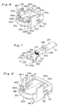
- Fig. 9 illustrates, in an exploded view, one of the prior art terminal caps, reference to which will now be made for the discussion of the prior art. As shown therein, the
terminal cap 1 includes a connector-side member 3 and a base-side member 4. The connector-side member 3 is a hollow body opening at top and bottom thereof as shown and is used to enclose aterminal tag 2a of aterminal element 2. The base-side member 4 is used to firmly hold aterminal stem 2c of theterminal element 2 which includes astem crimp 2b by which theterminal element 2 is firmly connected with abared end 9a of acable 9. Thisterminal cap 1 also includes first andsecond covers side member 3 and base-side member 4, respectively. Reference numeral 7 represents a terminal connector of anelectrical device 8 with which theterminal element 2 is electrically connected. - When the
terminal element 2 is to be covered by thisterminal cap 1, theterminal tag 2a of theterminal element 2 is first placed in the connector-side member 3, theterminal stem 2c and thewire end 9a are subsequently placed in the base-side member 4, and thesecond cover 6 is closed. Thereafter, the connector-side member 3 enclosing theterminal element 2 is placed over the terminal connector 7 from above as seen with aconductor bolt 10 of the terminal connector 7 inserted through a through-hole 2d in theterminal tag 2a. Thenut 12 is thereafter threaded onto theconductor bolt 10 to tighten theterminal tag 2a to the terminal connector 7, after which thetop opening 3a of the connector-side member 3 is covered by thefirst cover 5. - With this
terminal cap 1, however, the terminal element can move inside the connector-side member 3 in a lengthwise direction parallel to the direction in which thecable 9 may be pulled as indicated by arrows A and B, a lateral direction perpendicular to the lengthwise direction of thecable 9 as indicated by arrows C and D, and/or in a vertical direction perpendicular to the lengthwise direction of thecable 9 as indicated by arrows E and F, to such an extent as to result in a possible displacement in position of theterminal element 2 relative to theterminal cap 1. With theterminal cap 1 shown in Fig. 9 in particular, there is no restraint applied to vertical movement of theterminal tag 2a and, therefore, theterminal element 2 is apt to undergo an arbitrary motion considerably in the vertical direction. - When the position of the
terminal tag 2a in theterminal cap 1 shifts due to movement of theterminal element 2, theconductor bolt 10 does align with the through-hole 2d and it will become difficult to pass theconductor bolt 10 easily and quickly through the through-hole 2d when the connector-side member 3 is placed over the terminal connector 7. It is therefore necessary for the worker to adjust the position of theterminal element 2 before placing the connector-side member 3 over theterminal connector 2, increasing the complexity of the task and inviting a drop in productivity. - The present invention is designed to resolve the problems inherent in the conventional terminal cap as described above and has for its object to provide an improved terminal cap of a type in which any arbitrary motion of the terminal element within the terminal cap is minimized.
- To this end, the present invention provides a terminal cap comprising a fixed member having an opened top and including a connector-side member for accommodating a connecting member of a terminal element, and a base-side member for accommodating a base of the terminal element, said base having one end of a wire connected thereto; and a cover member comprising a first cover for closing the base-side member, and a second cover for closing the connector-side member. The connector-side member comprises a connector opening to which the mating side terminal connecting with the connecting member is inserted, and a wall member projecting in a direction reducing a diameter of the connector opening, and the connecting member of the terminal element passing through the connector opening and positioned at a bottom side of the connector-side member is engaged by said wall member.
- Preferably, an engaging rib engaging the connecting member of the terminal element for positioning the connecting member to the connector opening is provided at the wall member.
- The engaging rib may be tapered toward the open edge of the wall member.
- If desired, the first cover of the cover member may be connected to the fixed member such that the base-side member can be selectively opened and closed, and the second cover may be integrally formed with the first cover such that the connector-side member can be selectively opened and closed.
- The present invention also provides a terminal cap attachment structure for mounting a terminal cap. This attachment structure comprises a connecting member of the terminal element having a pair of engaging projections formed therein, each of said engaging projections including a first part projecting in mutual opposition widthwise to the terminal connecting member, and a second part formed by curving one end of the first part to project in a thickness direction of the connecting member. The terminal cap includes a fixed member having an opened top, said terminal cap including a connector-side member locating the connecting member of the terminal element, and a base-side member locating a base of the terminal element and the end of a wire connected to said base, and a cover member including a first cover for closing the base-side member and a second cover for closing the connector-side member. On the other hand, the connector-side member includes a connector opening to which a mating terminal connecting with the connecting member is inserted, and a wall member projecting in a direction reducing the diameter of the connector opening, and wherein one surface of the first part of the engaging projection of the connecting member inserted to the connector opening engages the wall member, and both sides of the first and second parts of the engaging projection engage the engaging ribs provided on the wall member.
- In this attachment structure, preferably, the end of the second parts of the engaging projections engages a detent provided on the terminal of the mating side.
- With the terminal cap according to the present invention, the connecting member is held without play inside the connector-side member of the terminal cap because the connecting member of the terminal passed through the connector opening engages the wall member provided on the connector opening of the connector-side member.
- In particular, when the engaging rib is provided on the wall member, movement is more positively prevented because the terminal connecting member is engaged by the wall member and the engaging ribs.
- In addition, when the engaging ribs are tapered, the connecting member inserted to the connector opening can be smoothly engaged by the engaging ribs and the wall member.
- Also, when the first cover of the cover member is connected to the fixed member such that the base-side member can be opened and closed, and the second cover is connected to the first cover such that the connecting member can be opened and closed, the space required for installation of the terminal cap is reduced because the space for opening the second cover is not necessary.
- Again, movement of the terminal in the direction pulling out the wire, side to side, and up or down can be prevented by providing a pair of engaging projections, comprising a first part projecting in mutual opposition widthwise to the terminal connecting member and a second part formed by curving the end of the first part to project in the thickness direction of the connecting member, on the connecting member of the terminal such that one surface of the first part of the engaging projection of the connecting member inserted to the connector opening engages the wall member, and both sides of the first and second parts of the engaging projections engage the engaging ribs provided on the wall member.
- If in this case the ends of the second parts of the engaging projections engage the detents provided on the mating terminal, the terminal and terminal cap will not rotate relative to the mating terminal.
- This and other objects and features of the present invention will become clear from the following description taken in conjunction with preferred embodiments thereof with reference to the accompanying drawings, in which like parts are designated by like reference numerals and in which:
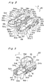
- Fig. 1 is a perspective view of a terminal cap according to a preferred embodiment of the present invention, which cap is shown as separated from a terminal connector;
- Fig. 2 is a perspective view of the terminal cap in a fully open position;
- Fig. 3 is a perspective view of the terminal cap in a half-closed position;
- Fig. 4 is a perspective view of the terminal cap in a completely closed position;
- Fig. 5 is a fragmentary perspective view, on an enlarged scale and as viewed from bottom, showing a mount area of the terminal cap;
- Fig. 6 is a view similar to Fig. 5, with a terminal element inserted therein;
- Fig. 7 is a perspective view of the terminal element secured to an electric wire, which can be employed in the practice of the present invention;
- Fig. 8 is a view similar to Fig. 5, showing a modification of the present invention; and
- Fig. 9 is an exploded view of the prior art terminal cap.
- The present invention will now be described in detail based on a preferred embodiment thereof shown in the accompanying drawings.
- Referring first to Fig. 1 to Fig. 7, a
terminal cap 20 according to the present invention encloses aterminal element 22 secured to a bare end of acable 21. Thisterminal element 22 is connected to aconnection terminal element 24 of anelectrical device 23. - As shown in Fig. 7, the
cable 21 comprises a plurality ofcore wires 21a bundled together and covered by an electrically insulating sheathing member 21b. For connection with theterminal element 22 in a manner which will be described subsequently, the sheathing member 21b at one end of thecable 21 is stripped off to expose one end of thewire bundle 21a. - The
terminal element 22 of one-piece construction is formed by stamping a conductive metal sheet to have aterminal tag 22b having a through-hole 22a defined therein, and abase 22e continued from theterminal tag 22b. Thebase 22e includes awire crimping part 22c for crimping the bared end of thewire bundle 21a for electrical connection of thecable 21 with theterminal element 22, and asheath crimping part 22d for firmly grasping the sheathing member 21b of thecable 21. A pair ofengaging projections 22f are also integrally formed with theterminal element 22 on respective sides of theterminal tag 22b so as to protrude in a direction generally perpendicular to the longitudinal axis of theterminal element 22. Each of theseengaging projections 22f has afirst part 22g extending slightly widthwise to theterminal tag 22b and asecond part 22h formed by bending the end of thefirst part 22g in the thickness direction of theterminal tag 22b. - The
terminal connector 24 projects vertically as shown in Fig. 1 from ahousing 23a of theelectrical device 23, and includes abolt member 25 connected electrically with an electric circuit installed inside thehousing 23. Afirst nut 27 is threaded onto thebolt member 25 with awasher 28 between thefirst nut 27 and the top of thehousing 23 to tighten and hold adetent member 29. Thisdetent member 29 hasdetents 29b formed integrally therewith and spaced at 90 degree intervals around aring body 29a of thedetent member 29. - The
terminal cap 20 of the first embodiment shown in Figs. 2 to 5 is made from an insulating resin, representing a generally cylindrical shape when a fixedmember 30 and acover member 31 are closed together. - The fixed
member 30 is of a generally boat-like configuration opening at 30f upwardly and including mutually opposing first andsecond side walls second end walls second side walls bottom wall 30e. The top opening 30f of the fixedmember 30 is adapted to be closed by thecover member 31. Rectangularly shaped thinflat guide pieces first wall 30a so as to project upwardly above the opening 30f, andlock tabs 33a and 33b are provided between theseguide pieces second wall 30b is connected to afirst cover part 54 of thecover member 31 by means of thinflexible hinges 35a and 35b. - The
first end wall 30c is formed with a semicircular cutout 36 communicated from the opening 30f with a flange 36a projecting outwardly around this cutout 36. - A portion of the
bottom wall 30e adjacent to thesecond end wall 30d and remote from thefirst end wall 30c is formed with aconnector opening 37 leaving a wall end 3g of thebottom wall 30e. In the illustrated embodiment, the part where thebottom wall 30e is present forms a base-side member 38 for positioning of thebase 22e of theterminal element 22 and that end of thecable 21 connected to thisbase 22e, and the part where theconnector opening 37 is defined is a connector-side member 39 for positioning of theterminal tag 22b of theterminal element 22. - The
second end wall 30d is generally arc-shaped and has a height difference provided between anend face 30d-1 adjacent theopening 30f and respective end faces 30a-1 and 30b-1 of the first andsecond side walls opening 30f. - At the connector-
side member 39 in which theconnector opening 37 is formed, aperimeter wall 41 is provided on the inside of thesecond end wall 30d and the first andsecond side walls connector opening 37. The width of thisperimeter wall 41 is approximately constant in the area of thesecond end wall 30d, but becomes gradually smaller in the area of the first andsecond side walls second end wall 30d to theend 30g of thebottom wall 30e. Theperimeter wall 41 is continued from theend face 30d-1 of thesecond end wall 30d with theperimeter wall 41 lying on the same plane as theend face 30d-1. The width W1 at the widest part of theperimeter wall 41 is narrower than the width W2 between the engagingprojections terminal element 22. - A substantially
arcuate guide projection 44 is integrally formed on an upper surface of theperimeter wall 41 adjacent theopening 30f so as to extend substantially parallel to thesecond end wall 30d. - As shown in Fig. 5, first
engaging ribs bottom wall 30e where the first andsecond side walls second end wall 30d. These firstengaging ribs second side walls perimeter wall 41. - Also provided on the
perimeter wall 41 near the firstengaging ribs ribs engaging ribs - A second engaging rib 47 is also provided on the
perimeter wall 41 at a position corresponding to an end of thesecond end wall 30d. This second engaging rib 47 comprises afirst part 47a lying perpendicular to an inner face of that end of thesecond end wall 30d, and asecond part 47b lying perpendicular to thefirst part 47a. - Protective arms 48-1 and 48-2 extending toward the
bottom wall 30e and having a width greater than that of the engagingprojections terminal element 22 are provided where the first andsecond side walls second end wall 30d. Side faces 48a of the protective arms 48-1 and 48-2 adjacent thesecond end wall 30d are positioned on approximately the same plane as these firstengaging ribs - Respective portions of the first and
second side walls first end wall 30c are inwardly curved as indicated by 50. Thesecurved portions 50 have respective end faces adjacent thesecond end wall 30d lying on the same plane as theside face 48b of the protective arm adjacent thefirst end wall 30c so as to form a thirdengaging rib 50a that projects in a direction reducing the diameter of theconnector opening 37. - A
channel 52 having a rectangular cross-section is formed at aninside face 48c of each of the protective arms 48-1 and 48-2 so as to extend from theend 48d past theperimeter wall 41 and towards theopening 30f side. Respective ends of thesechannels 52 adjacent theopening 30f are utilized as lockingrecesses 52a in which lockingtabs 63 provided on thesecond cover part 55 of thecover member 31 are engageable as will be described below. - The
cover member 31 comprises afirst cover part 54 and asecond cover part 55 connected in the lengthwise direction of thecable 21 by means of asnap mechanism 53. - The
first cover part 54 includes first andsecond side walls second side walls top wall 54d opening at 54e downwardly as viewed in Fig. 4, and the side opposite the end wall 54c is defined by anopen end 54f. - Locking arms 57-1 and 57-2 having
respective lock holes 57a defined therein are provided on thefirst side wall 54a so as to project outwardly from theopening 54e at a predetermined interval. Thesecond side wall 54b is contiguous to thesecond wall 30b of the fixedmember 30 via thehinges 35a and 35b. - A
semicircular cutout 58 is provided at the end wall 54c with aflange 58a projecting outwardly from around the perimeter in a manner similar to the semicircular cutout 36 in thesecond end wall 30d of the fixedmember 30. - A generally inverted
U-shaped arch 60 is provided inside thetop wall 54d, and a connectingmember 61 is provided at theopening 54e. - The
second cover part 55 is of a generally boat-like configuration opening downwardly so as to confront theopening 30f in the fixedmember 30 and includes first andsecond side walls end wall 55c connecting respective ends of the first andsecond side walls top wall 55d. Thissecond cover part 55 open downwardly as viewed in Fig. 1, the opening consisting of afirst opening 55f, corresponding in position to theconnector opening 37, and asecond opening 55g defined at an area corresponding to thefirst cover part 54. - The spacing between the first and
second side walls second side walls member 30. In addition, lockingtabs 63 engageable in the respective locking recesses 52a of the fixedmember 30 are formed in the first andsecond side walls - The
end wall 55c forms an arc of a curvature approximately matching that of thesecond end wall 30d of the fixedmember 30. - As shown in Fig. 4, the
top wall 55d in thesecond cover part 55 has aflat region 55h, and an area between thisflat region 55h and theend wall 55c is connected by a curved face 55i which has a predetermined slope, the edge of which extends slightly beyond the end of theend wall 55c. - The
top wall 54d of thefirst cover part 54 and thetop wall 55d of thesecond cover part 55 are connected by means of a pair ofhinges - A
rectangular cutout 64 is formed in thesecond cover part 55 between the connecting parts of thehinges member 65, which bends flexibly towards thecutout 64 in theend wall 55c. The other end of this L-shapedmember 65 is contiguous to the connectingmember 61 of thefirst cover part 54. - In this illustrated embodiment, the
first cover part 54 and thesecond cover part 55 are connected by thesnap mechanism 53 comprising thehinges member 65 such that thefirst cover part 54 can be selectively pivoted with a moderate touch between an open position shown in Fig. 3 and a closed position shown in Fig. 4. - The
terminal cap 20 according to the present invention so constructed is fitted to theterminal element 22 to enclose the latter as will now be described. - Assuming that the
terminal element 22 is in such a condition as shown in Fig. 2 with thecover member 31 swung to the opened position, theterminal element 22 connected to thecable 21 is passed to theconnector opening 37 from top as viewed in Fig. 2. At this time, because the width W1 of theperimeter wall 41 is less than the width W2 in the area of the engagingprojections 22f of theterminal element 22, theterminal element 22 is inserted to theconnector opening 37 such that the engagingprojections perimeter wall 41. - After the
terminal cap 20 has been turned relative to theterminal element 22 to position the engagingprojections 22f of theterminal element 22 to align with the widthwise direction of theperimeter wall 41, theterminal cap 20 is moved in a direction along which theterminal element 22 can be pulled from theconnector opening 37. By so doing, as shown in Fig. 6, the engagingprojections 22f of theterminal element 22 are positioned inside the protective arms 48-1 and 48-2. In other words, the top of thefirst part 22g of the engagingprojections 22f of theterminal element 22 is engaged against the bottom of theperimeter wall 41, i.e., in contact with the face on thebottom wall 30e side, and both of the first andsecond parts projections 22f are engaged by the first and thirdengaging ribs terminal tag 22b of theterminal element 22 is positioned at the connector-side member 39 of the fixedmember 30, and the engagingprojections 22f are positioned at the base-side member 38. - Next, the
first cover part 54 is rotated relative to the fixedmember 30 about thehinges 35a and 35b as indicated by the arrow X in Fig. 2 to cover the base-side member 38. Thelock tabs 33a and 33b are then engaged in the lock holes 57a of the locking arms 57-1 and 57-2, and thefirst cover part 54 and base-side member 38 are thus fastened together as shown in Fig. 3. The lock holes 57a and the lock tabs 33 can be positively engaged at this time because the locking arms 57 are guided by the space between theguide pieces 32a to 32c. In addition, thesecond cover part 55 is opened back over thefirst cover part 54, which is closed over the base-side member 38 as shown in Fig. 3, and because thesecond cover part 55 is not positioned at the side of the fixedmember 30, the amount of space required for mounting is reduced that much. - In this state, the
cutouts 36 and 58 formed in thefirst end wall 30c of the fixedmember 30 and the end wall 54c of thefirst cover part 54 form an electric cable insertion hole through which thecable 21 is conductive from inside the base-side member 38 to the outside, and theflanges 36a and 58a form a cylindrical passage through which the cable extends outwardly from theterminal cap 20. - As described above, when the base-
side member 38 of the fixedmember 30 is closed by thefirst cover part 54, play in the direction as indicated by arrows A and B in Fig. 1 is restricted by engagement of the engagingprojections engaging ribs 45 and 50a. In addition, lateral play perpendicular to the direction as indicated by arrows C and D in Fig. 1 is restricted by contact between the second part 21h of the engagingprojections inside face 48c of the protective arms 48. Play in the vertical direction of theterminal element 22 as indicated by arrows E and F in Fig. 1 is restricted by engagement of thefirst part 22g of the engaging projections and theperimeter wall 41. Thus, in the illustrated embodiment theterminal element 22 is held firmly positioned to theterminal cap 20, and the position of the through-hole 22a in theterminal tag 22b of theterminal element 22 is held at a predetermined position in theconnector opening 37. - Thereafter, the
terminal cap 20 housing theterminal element 22 in the manner described hereinbefore is placed over theterminal connector 24 with thebolt member 25 passing through the through-hole 22a in theterminal tag 22b. At this time, theterminal tag 22b is held positioned substantially immovably in theterminal element 22 as described above, and the worker can thus reliably pass thebolt member 25 through the through-hole 22a by simply putting theterminal cap 20 over themating terminal connector 24 without adjusting the position of theterminal element 22 to theterminal cap 20. Also, because thesecond parts projections detents 29b of thedetent member 29 when theterminal cap 20 covers theterminal connector 24, theterminal cap 20 andterminal element 22 will not turn relative to theterminal connector 24. - The
second nut 67 is then threaded onto thebolt member 25, and theterminal tag 22b of theterminal element 22 is fastened firmly to thebolt member 25. Thesecond cover part 55 is also pivoted in the direction of arrow Y to the closed position. At this time, the first andsecond side walls second cover part 55 are inserted to the inside of the first andsecond side walls member 30, the lockingtabs 63 engage the locking recesses 52a, and thesecond cover part 55 is thus fastened to the fixedmember 30. - The connecting members of the
terminal element 22 andterminal connector 24 can be prevented from contacting other parts, and theterminal element 22 can be protected against water, dust, etc., because theterminal element 22 covered by theterminal cap 20 is connected to theterminal connector 24. - The terminal cap referred to above may be modified as shown in Fig. 8. More specifically, the terminal cap shown therein has first engaging
ribs 45A' and 45B' and reinforcingribs 46A' and 46B' formed on theperimeter wall 41 so as to represent a taperedshape having tapers second end wall 30d towards the inside edge of theperimeter wall 41. In this modified terminal cap, the second engaging rib 47 employed in the foregoing embodiment is dispensed with. - Because of this configuration as shown in Fig. 8, if the
terminal element 22 inserted in theconnector opening 37 is moved in the direction removing it from theconnector opening 37, the engagingprojections 22f of theterminal element 2 are guided by thetapers perimeter wall 41 and the firstengaging ribs 45A' and 45B' and the thirdengaging rib 50a. - As is clear from the above description, movement of the terminal can be prevented with a terminal cap according to the present invention because a connector opening to which the mating terminal connecting with the terminal connector and a perimeter wall projecting in the direction reducing the diameter of the connector opening are provided in the connector-side member locating the terminal connector, the engaging projections of the connecting member inserted to the connector opening engage the perimeter wall, and both sides of the engaging projections engage the engaging ribs provided on the perimeter wall.
- Therefore, because the terminal element is positively held positioned to the connector-side member by means of a terminal cap according to the present invention, the mating terminal element and the connector terminal can be positively connected by inserting the mating terminal element to this connector-side member. For example, if a through-hole is provided in the connector terminal and the mating terminal element has a bolt member, and when the connector-side member covers the mating terminal, the bolt member can be positively passed through the through-hole and there is no need for the worker to adjust the position of the connector terminal inside the terminal cap. Thus, with the terminal cap according to the present invention, mounting to the terminal is simple, and productivity can be improved.
- Furthermore, when the engaging ribs have a tapered shape, the connector terminal can be smoothly engaged with the perimeter wall and the engaging ribs if the terminal cap is moved in the direction pulling the wire out after the connector terminal is inserted to the connector opening.
- In addition, the space for opening the second cover part is not necessary and the space required for the installation task can be reduced because when the second cover part can fold over the first cover part when it is open if the first cover part is connected to the fixed member in a manner enabling the base-side member to open and close, and the second cover part is connected to the first cover part in a manner enabling the connecting member to be opened and closed.
- In addition, rotation of the terminal cap and terminal element to the mating connector terminal can be prevented, and various other benefits obtained, if the engaging projections comprise a first part projecting in the widthwise direction of the connector terminal and a second part, which is formed by bending the end of the first part, projecting in the thickness direction of the connector terminal, and the end of this second part engages detents provided on the connector terminal.
- Although the present invention has been described in connection with the preferred embodiment thereof with reference to the accompanying drawings, it is to be noted that various changes and modifications are apparent to those skilled in the art. Such changes and modifications are to be understood as included within the scope of the present invention as defined by the appended claims, unless they depart therefrom.
Claims (7)
- A terminal cap comprising
a feed member (30) having an opened top and including a connector-side member (39) for accommodating a connecting member (22b) of a terminal element (22), and a base-side member (38) for accommodating a base (22e) of the terminal element, said base having one end of a wire (21) connected thereto, and
a cover member (31) comprising a first cover (54) for closing the base-side member (38) and a second cover (55) for closing the connector-side member (39),
wherein the connector-side member (39) comprises a connector opening (37) into which a mating terminal connector (24) to be connected with the connecting member (22b) is inserted,
characterized by a wall member (41) projecting in a direction reducing the diameter of the connector opening (37), the connecting member (22b) of the terminal element inserted through the connector opening and positioned at a bottom side of the connector-side member (39) being engaged by said wall member. - A terminal cap according to claim 1, wherein an engaging rib (45A, 45B; 45A') engaging the connecting member (22b) of the terminal element (22) for positioning the connecting member in the connector opening (37) is provided at the wall member (41).
- A terminal cap according to claim 2, wherein said engaging rib (45A') is tapered toward the open edge of the wall member (41).
- A terminal cap according to any of the claims 1 to 3, wherein the first cover (54) of the cover member (31) is connected to the fixed member (30) such that the base-side member (38) can be selectively opened and closed, and the second cover (55) is hingedly connected to the first cover (54) such that the connector-side member (39) can be opened and closed.
- A terminal cap according to claim 4, wherein said second cover (55) is integrally molded contiguous to the first cover (54).
- A terminal cap attachment structure for mounting a terminal cap (20), which comprises:
a connecting member (22b) of a terminal element (22); and
said terminal cap (20) comprising a fixed member (30) having an opened top and including a connector-side member (39) accommodating said connecting member (22b), and a base-side member (38) accommodating a base (22e) of the terminal element (22) and the end of a wire (21) connected to said base, said terminal cap further including a cover member (31) including a first cover (54) for closing the base-side member (38) and a second cover (55) for closing the connector-side member (39),
the connector-side member (39) comprising a connector opening (37) into which a mating terminal connector (24) to be connected with the connecting member (22b) is inserted,
characterized in that
said connecting member (22b) has a pair of mutually opposed engaging projections (22f) each of which includes a first part (22g) projecting widthwise of the connecting member, and a second part (22h) formed by curving one end of the first part to project in a thickness direction of the connecting member,
said connector-side member (39) comprises a wall member (41) projecting in a direction reducing the diameter of the connector opening (37), and
one surface of the first part (22g) of the engaging projection (22f) of the connecting member inserted into the connector opening engages the wall member (41) and both sides of the first and second parts (22g, 22h) of the engaging projection engage engaging ribs (45A, 45B; 45A') provided on the wall member (41). - A terminal cap attachment structure as claimed in claim 6, wherein the ends of the second parts (22h) of the engaging projections (22f) engage a detent (29b) provided on a terminal (24) mating with said terminal element (22).
Applications Claiming Priority (2)
| Application Number | Priority Date | Filing Date | Title |
|---|---|---|---|
| JP1992088982U JP2578848Y2 (en) | 1992-12-25 | 1992-12-25 | Terminal cap and structure for attaching terminal cap to terminal |
| JP88982/92U | 1992-12-25 |
Publications (3)
| Publication Number | Publication Date |
|---|---|
| EP0603872A2 true EP0603872A2 (en) | 1994-06-29 |
| EP0603872A3 EP0603872A3 (en) | 1995-03-08 |
| EP0603872B1 EP0603872B1 (en) | 1997-04-16 |
Family
ID=13958010
Family Applications (1)
| Application Number | Title | Priority Date | Filing Date |
|---|---|---|---|
| EP93120741A Expired - Lifetime EP0603872B1 (en) | 1992-12-25 | 1993-12-22 | Terminal cap and cap attachment structure |
Country Status (4)
| Country | Link |
|---|---|
| US (1) | US5413500A (en) |
| EP (1) | EP0603872B1 (en) |
| JP (1) | JP2578848Y2 (en) |
| DE (1) | DE69309872T2 (en) |
Cited By (11)
| Publication number | Priority date | Publication date | Assignee | Title |
|---|---|---|---|---|
| EP0765005A3 (en) * | 1995-09-19 | 1997-05-21 | Sumitomo Wiring Systems | A cover equipped electrical connection device and a cover for an electrical connection device |
| EP1056157A3 (en) * | 1999-05-27 | 2002-03-13 | Sumitomo Wiring Systems, Ltd. | Protective cover for battery connection terminal and assembly of the protective cover and battery connection terminal |
| RU2202993C2 (en) * | 2000-10-12 | 2003-04-27 | Российский научно-исследовательский институт травматологии и ортопедии им. Р.Р. Вредена | Apparatus for diluting bone cement and introducing the same into medullary canal |
| FR2841048A1 (en) * | 2002-06-13 | 2003-12-19 | Legrand Sa | Electrical cable/conductor wire connection having body with click fit mechanism shaft and foot section attached shaft/connector and side wings body attached swinging open and closed position fixed. |
| EP1401052A1 (en) * | 2000-03-09 | 2004-03-24 | Sumitomo Wiring Systems, Ltd. | A construction and a terminal cap for preventing an erroneous connection |
| WO2009100887A1 (en) * | 2008-02-13 | 2009-08-20 | Newfrey Llc | Retaining device for cable lugs |
| GB2469537A (en) * | 2009-04-15 | 2010-10-20 | Graham Falshaw-Pickup | Quick earth connection for agricultural use |
| CN102959806A (en) * | 2010-11-15 | 2013-03-06 | 矢崎总业株式会社 | Connector for high-voltage use |
| EP2879201A4 (en) * | 2012-08-10 | 2015-07-01 | Autonetworks Technologies Ltd | BATTERY WIRING MODULE |
| EP3079205A1 (en) * | 2015-04-08 | 2016-10-12 | DET International Holding Limited | Mounting clip |
| WO2017009559A1 (en) * | 2015-07-16 | 2017-01-19 | Safran Electrical & Power | Insulator for a pivotable electrical connection |
Families Citing this family (45)
| Publication number | Priority date | Publication date | Assignee | Title |
|---|---|---|---|---|
| JP3042579B2 (en) * | 1994-07-22 | 2000-05-15 | 矢崎総業株式会社 | Screw structure of distribution box |
| JP3230955B2 (en) * | 1995-08-29 | 2001-11-19 | 矢崎総業株式会社 | Connector with protective cover |
| US5645448A (en) * | 1995-10-16 | 1997-07-08 | Yazaki Corporation | Battery connecting module with fuse mounting |
| USD384641S (en) * | 1996-01-19 | 1997-10-07 | Motorola, Inc. | External connector for a portable communication device |
| US5791936A (en) * | 1996-06-20 | 1998-08-11 | Yazaki Corporation | Protective cover for ground junction connector |
| DE19813370C1 (en) * | 1998-03-26 | 1999-09-30 | Wolfgang B Thoerner | Cable lug |
| US6126493A (en) * | 1998-08-10 | 2000-10-03 | Lear Corporation | Electrical fastener |
| JP2000223168A (en) | 1999-01-28 | 2000-08-11 | Sumitomo Wiring Syst Ltd | Connection member, and connecting method of transformer to high-voltage wire |
| ES1044129Y (en) * | 1999-08-10 | 2000-08-16 | Mecanismos Aux Ind | DEVICE FOR FIXING ELECTRICAL COMPONENTS. |
| EP1531521B1 (en) | 2000-03-07 | 2008-04-30 | Sumitomo Wiring Systems, Ltd. | A construction for preventing erroneous assembling of battery terminals, a battery and a set of terminals |
| US6520812B1 (en) | 2000-08-30 | 2003-02-18 | Antaya Technologies Corporation | Connector terminal with resilient contacts |
| US7056161B2 (en) | 2001-02-20 | 2006-06-06 | Newfrey Llc | Grounding stud |
| US6746285B2 (en) * | 2001-02-20 | 2004-06-08 | Newfrey Llc | Grounding stud |
| EP1239506B1 (en) * | 2001-03-07 | 2012-04-25 | Yazaki Corporation | Protective cover and fuse box |
| JP2003317823A (en) * | 2002-04-25 | 2003-11-07 | Yazaki Corp | Terminal protection cap |
| JP3888546B2 (en) * | 2003-02-19 | 2007-03-07 | 矢崎総業株式会社 | Terminal cap |
| US20050077437A1 (en) * | 2003-10-14 | 2005-04-14 | Widlacki Don F. | Removably mountable wire, rope, cable and hose retention device |
| US7491101B2 (en) * | 2004-06-17 | 2009-02-17 | Illinois Tool Works Inc. | Self-locking wire terminal and shape memory wire termination system |
| DE102004054782B3 (en) * | 2004-11-12 | 2006-06-14 | Lisa Dräxlmaier GmbH | Grounding cable lug and stud e.g. grounding stud, mounting arrangement for motor vehicle, has assembly aid detachably connected with distributor and including protruding center unit whose cross-section corresponds to stud cross-section |
| KR100846074B1 (en) * | 2005-05-09 | 2008-07-14 | 주식회사 엘지화학 | Three-dimensional electrode terminal of pouch type battery |
| DE102006056065B4 (en) | 2006-11-20 | 2018-08-09 | Newfrey Llc | Pre-assembled contacting unit and mounting arrangement |
| US20080194126A1 (en) * | 2007-02-12 | 2008-08-14 | Ford Global Technologies, Llc | System for fastening components |
| JP5050949B2 (en) * | 2008-03-21 | 2012-10-17 | 住友電装株式会社 | Terminal cover |
| US8047868B1 (en) * | 2008-03-28 | 2011-11-01 | GEP Power Products, Inc. | Stud-type junction block |
| US8313343B2 (en) | 2010-08-31 | 2012-11-20 | Hamilton Sundstrand Corporation | Terminal block cover with nut retention feature |
| US8492015B2 (en) | 2010-10-22 | 2013-07-23 | Nissan North America, Inc. | Battery fuse terminal cover with latch |
| US8338710B2 (en) * | 2010-11-03 | 2012-12-25 | Ford Global Technologies, Llc | Short-preventing shield for wire harness terminals |
| US8313351B2 (en) | 2011-01-21 | 2012-11-20 | Hamilton Sundstrand Corporation | High altitude, high voltage terminal block assembly |
| US8197288B1 (en) | 2011-04-13 | 2012-06-12 | Hamilton Sundstrand Corporation | Terminal block having adjoining transverse surfaces with protrusions |
| US8480423B2 (en) * | 2011-08-16 | 2013-07-09 | Tyco Electronics Corporation | Contact region of an electrically conductive member |
| US9071101B2 (en) | 2012-02-15 | 2015-06-30 | Hamilton Sundstrand Corporation | High altitude, high voltage rear terminal block assembly |
| SE537733C2 (en) * | 2012-07-04 | 2015-10-06 | Scania Cv Ab | Procedure for connecting a voltage source |
| JP6265647B2 (en) * | 2013-08-06 | 2018-01-24 | 矢崎総業株式会社 | Terminal fixing auxiliary member |
| US9680239B2 (en) | 2014-04-23 | 2017-06-13 | Ramco Specialties, Inc. | Grounding stud and electrical connections |
| DE102014216711A1 (en) | 2014-08-22 | 2016-03-10 | Bayerische Motoren Werke Aktiengesellschaft | Electrical connector system with improved high voltage protection |
| DE102015203009B4 (en) * | 2015-02-19 | 2021-03-18 | Zf Friedrichshafen Ag | Piston rod cylinder unit with one line |
| KR101872843B1 (en) * | 2016-12-01 | 2018-08-02 | 주식회사 유라코퍼레이션 | Cover structure for power connector device |
| JP6744578B2 (en) * | 2017-01-26 | 2020-08-19 | 住友電装株式会社 | Cover member and device connector |
| IT201700075174A1 (en) * | 2017-07-05 | 2019-01-05 | Davide Brescianini | Cover element for alternator pole. |
| KR102248167B1 (en) * | 2017-07-28 | 2021-05-04 | 현대모비스 주식회사 | Wire clip apparatus for motor |
| US11170916B2 (en) | 2018-11-05 | 2021-11-09 | Lear Corporation | Cover |
| DE102020002701B4 (en) | 2020-05-06 | 2023-10-05 | Auto-Kabel Management Gmbh | Seal housing |
| JP7491247B2 (en) * | 2021-03-17 | 2024-05-28 | 住友電装株式会社 | Terminal covers and terminals with covers |
| JP7688064B2 (en) * | 2023-04-03 | 2025-06-03 | 矢崎総業株式会社 | Terminal cover and terminal with cover |
| EP4697520A1 (en) * | 2024-08-14 | 2026-02-18 | Aptiv Technologies AG | Electrical connector for equipping a connection interface of a header |
Family Cites Families (7)
| Publication number | Priority date | Publication date | Assignee | Title |
|---|---|---|---|---|
| US3633154A (en) * | 1970-02-03 | 1972-01-04 | Hershey Glantz | Housing for battery terminals |
| US4572878A (en) * | 1984-12-19 | 1986-02-25 | General Motors Corporation | Battery temperature sensor and housing therefor |
| JPS62129775A (en) * | 1985-12-02 | 1987-06-12 | Hitachi Medical Corp | Simultaneously counting circuit of position ct apparatus |
| FR2606558B1 (en) * | 1986-11-07 | 1989-01-20 | Lacroix Jacques | CONNECTION DEVICE |
| JPH0463567U (en) * | 1990-10-11 | 1992-05-29 | ||
| EP0534646A3 (en) * | 1991-09-27 | 1993-07-07 | United Technologies Automotive, Inc. | Battery connector cover |
| US5169338A (en) * | 1991-12-10 | 1992-12-08 | United Technologies Automotive Inc. | Battery connector cover |
-
1992
- 1992-12-25 JP JP1992088982U patent/JP2578848Y2/en not_active Expired - Lifetime
-
1993
- 1993-12-16 US US08/167,037 patent/US5413500A/en not_active Expired - Lifetime
- 1993-12-22 EP EP93120741A patent/EP0603872B1/en not_active Expired - Lifetime
- 1993-12-22 DE DE69309872T patent/DE69309872T2/en not_active Expired - Lifetime
Cited By (24)
| Publication number | Priority date | Publication date | Assignee | Title |
|---|---|---|---|---|
| US5804770A (en) * | 1995-09-19 | 1998-09-08 | Sumitomo Wiring Systems, Ltd. | Cover equipped electrical connection device and a cover for an electrical connection device |
| CN1054706C (en) * | 1995-09-19 | 2000-07-19 | 住友电装株式会社 | Cover equipped electrical connection device and cover electrical connection device |
| EP0765005A3 (en) * | 1995-09-19 | 1997-05-21 | Sumitomo Wiring Systems | A cover equipped electrical connection device and a cover for an electrical connection device |
| EP1056157A3 (en) * | 1999-05-27 | 2002-03-13 | Sumitomo Wiring Systems, Ltd. | Protective cover for battery connection terminal and assembly of the protective cover and battery connection terminal |
| US6426465B1 (en) | 1999-05-27 | 2002-07-30 | Sumitomo Wiring Systems, Ltd. | Protective cover for battery connection terminal, and assembly of the protective cover and battery connection terminal |
| EP1401052A1 (en) * | 2000-03-09 | 2004-03-24 | Sumitomo Wiring Systems, Ltd. | A construction and a terminal cap for preventing an erroneous connection |
| RU2202993C2 (en) * | 2000-10-12 | 2003-04-27 | Российский научно-исследовательский институт травматологии и ортопедии им. Р.Р. Вредена | Apparatus for diluting bone cement and introducing the same into medullary canal |
| FR2841048A1 (en) * | 2002-06-13 | 2003-12-19 | Legrand Sa | Electrical cable/conductor wire connection having body with click fit mechanism shaft and foot section attached shaft/connector and side wings body attached swinging open and closed position fixed. |
| US8057268B2 (en) | 2008-02-13 | 2011-11-15 | Newfrey Llc | Retaining device for cable lugs |
| WO2009100887A1 (en) * | 2008-02-13 | 2009-08-20 | Newfrey Llc | Retaining device for cable lugs |
| GB2469537B (en) * | 2009-04-15 | 2013-09-25 | Graham Falshaw-Pickup | Agri quick earth |
| GB2469537A (en) * | 2009-04-15 | 2010-10-20 | Graham Falshaw-Pickup | Quick earth connection for agricultural use |
| CN102959806A (en) * | 2010-11-15 | 2013-03-06 | 矢崎总业株式会社 | Connector for high-voltage use |
| EP2642601A4 (en) * | 2010-11-15 | 2014-04-16 | Yazaki Corp | Connector for high-voltage use |
| CN102959806B (en) * | 2010-11-15 | 2015-03-11 | 矢崎总业株式会社 | Connector for high-voltage use |
| US9893340B2 (en) | 2012-08-10 | 2018-02-13 | Autonetworks Technologies, Ltd. | Battery wiring module |
| EP2879201A4 (en) * | 2012-08-10 | 2015-07-01 | Autonetworks Technologies Ltd | BATTERY WIRING MODULE |
| EP3079205A1 (en) * | 2015-04-08 | 2016-10-12 | DET International Holding Limited | Mounting clip |
| US9825378B2 (en) | 2015-04-08 | 2017-11-21 | Det International Holding Limited | Mounting clip |
| WO2017009559A1 (en) * | 2015-07-16 | 2017-01-19 | Safran Electrical & Power | Insulator for a pivotable electrical connection |
| FR3039010A1 (en) * | 2015-07-16 | 2017-01-20 | Labinal Power Systems | ISOLATOR FOR A PIVOTABLE ELECTRICAL CONNECTION |
| CN107925173A (en) * | 2015-07-16 | 2018-04-17 | 赛峰电气与电源公司 | Insulator for pivotable electrical connector |
| CN107925173B (en) * | 2015-07-16 | 2019-08-16 | 赛峰电气与电源公司 | Insulators for pivotable electrical connections |
| US10439303B2 (en) | 2015-07-16 | 2019-10-08 | Safran Electrical & Power | Insulator for a pivotable electrical connection |
Also Published As
| Publication number | Publication date |
|---|---|
| DE69309872D1 (en) | 1997-05-22 |
| DE69309872T2 (en) | 1997-11-13 |
| US5413500A (en) | 1995-05-09 |
| EP0603872A3 (en) | 1995-03-08 |
| EP0603872B1 (en) | 1997-04-16 |
| JPH0654222U (en) | 1994-07-22 |
| JP2578848Y2 (en) | 1998-08-20 |
Similar Documents
| Publication | Publication Date | Title |
|---|---|---|
| EP0603872B1 (en) | Terminal cap and cap attachment structure | |
| US6200162B1 (en) | Shielding terminal | |
| JP3365550B2 (en) | Shield terminal | |
| US6206727B1 (en) | Terminal and crimping method | |
| US6210223B1 (en) | Shielded connector, a set of shielded connectors and method for connecting a shielded connector with a shielded cable | |
| EP1992048B1 (en) | Connector cover with fastener | |
| JPH0538547Y2 (en) | ||
| US6056582A (en) | Lever fitting connector | |
| US4127315A (en) | Cable clamp and hood constructions for use with ribbon connectors | |
| JPH0636825A (en) | Cable-fixing structure of electric connector | |
| EP0490078A2 (en) | Shielded electrical connector | |
| CN102474044A (en) | Connector | |
| US6254436B1 (en) | Electrical connector for automotive lamp | |
| JP2002042990A (en) | Shield terminal | |
| EP1909363B1 (en) | A cable holder and a cable holding method | |
| EP1235305B1 (en) | Connector | |
| US5226830A (en) | Connector device | |
| US6065982A (en) | Lever-engaged connector | |
| JPS64791B2 (en) | ||
| JP3998922B2 (en) | connector | |
| CN111357154B (en) | Connecting device and method for connecting conductors, in particular shielding conductors, to an electronics housing | |
| JPH07272784A (en) | Receptacle contact | |
| US20100112857A1 (en) | Conducting device for the electric contact of a conducting shielding sheath | |
| JP2010067457A (en) | Wire harness containing short circuit, and method for manufacturing the same | |
| US5061208A (en) | Conductive shell for clamping onto a shielded electrical connector |
Legal Events
| Date | Code | Title | Description |
|---|---|---|---|
| PUAI | Public reference made under article 153(3) epc to a published international application that has entered the european phase |
Free format text: ORIGINAL CODE: 0009012 |
|
| AK | Designated contracting states |
Kind code of ref document: A2 Designated state(s): DE GB |
|
| PUAL | Search report despatched |
Free format text: ORIGINAL CODE: 0009013 |
|
| AK | Designated contracting states |
Kind code of ref document: A3 Designated state(s): DE GB |
|
| 17P | Request for examination filed |
Effective date: 19950516 |
|
| 17Q | First examination report despatched |
Effective date: 19951016 |
|
| GRAG | Despatch of communication of intention to grant |
Free format text: ORIGINAL CODE: EPIDOS AGRA |
|
| GRAH | Despatch of communication of intention to grant a patent |
Free format text: ORIGINAL CODE: EPIDOS IGRA |
|
| GRAH | Despatch of communication of intention to grant a patent |
Free format text: ORIGINAL CODE: EPIDOS IGRA |
|
| GRAA | (expected) grant |
Free format text: ORIGINAL CODE: 0009210 |
|
| AK | Designated contracting states |
Kind code of ref document: B1 Designated state(s): DE GB |
|
| REF | Corresponds to: |
Ref document number: 69309872 Country of ref document: DE Date of ref document: 19970522 |
|
| PLBE | No opposition filed within time limit |
Free format text: ORIGINAL CODE: 0009261 |
|
| STAA | Information on the status of an ep patent application or granted ep patent |
Free format text: STATUS: NO OPPOSITION FILED WITHIN TIME LIMIT |
|
| 26N | No opposition filed | ||
| REG | Reference to a national code |
Ref country code: GB Ref legal event code: IF02 |
|
| PGFP | Annual fee paid to national office [announced via postgrant information from national office to epo] |
Ref country code: GB Payment date: 20121219 Year of fee payment: 20 |
|
| PGFP | Annual fee paid to national office [announced via postgrant information from national office to epo] |
Ref country code: DE Payment date: 20121219 Year of fee payment: 20 |
|
| REG | Reference to a national code |
Ref country code: DE Ref legal event code: R071 Ref document number: 69309872 Country of ref document: DE |
|
| REG | Reference to a national code |
Ref country code: GB Ref legal event code: PE20 Expiry date: 20131221 |
|
| PG25 | Lapsed in a contracting state [announced via postgrant information from national office to epo] |
Ref country code: DE Free format text: LAPSE BECAUSE OF EXPIRATION OF PROTECTION Effective date: 20131224 Ref country code: GB Free format text: LAPSE BECAUSE OF EXPIRATION OF PROTECTION Effective date: 20131221 |