EP0603313B1 - Cervical discectomy instruments - Google Patents
Cervical discectomy instruments Download PDFInfo
- Publication number
- EP0603313B1 EP0603313B1 EP92920314A EP92920314A EP0603313B1 EP 0603313 B1 EP0603313 B1 EP 0603313B1 EP 92920314 A EP92920314 A EP 92920314A EP 92920314 A EP92920314 A EP 92920314A EP 0603313 B1 EP0603313 B1 EP 0603313B1
- Authority
- EP
- European Patent Office
- Prior art keywords
- tube
- base
- bore
- proximal end
- cutter
- Prior art date
- Legal status (The legal status is an assumption and is not a legal conclusion. Google has not performed a legal analysis and makes no representation as to the accuracy of the status listed.)
- Expired - Lifetime
Links
Images


Classifications
-
- A—HUMAN NECESSITIES
- A61—MEDICAL OR VETERINARY SCIENCE; HYGIENE
- A61B—DIAGNOSIS; SURGERY; IDENTIFICATION
- A61B17/00—Surgical instruments, devices or methods, e.g. tourniquets
- A61B17/16—Bone cutting, breaking or removal means other than saws, e.g. Osteoclasts; Drills or chisels for bones; Trepans
- A61B17/1604—Chisels; Rongeurs; Punches; Stamps
-
- A—HUMAN NECESSITIES
- A61—MEDICAL OR VETERINARY SCIENCE; HYGIENE
- A61B—DIAGNOSIS; SURGERY; IDENTIFICATION
- A61B17/00—Surgical instruments, devices or methods, e.g. tourniquets
- A61B17/32—Surgical cutting instruments
- A61B17/320016—Endoscopic cutting instruments, e.g. arthroscopes, resectoscopes
-
- A—HUMAN NECESSITIES
- A61—MEDICAL OR VETERINARY SCIENCE; HYGIENE
- A61B—DIAGNOSIS; SURGERY; IDENTIFICATION
- A61B17/00—Surgical instruments, devices or methods, e.g. tourniquets
- A61B17/34—Trocars; Puncturing needles
- A61B17/3417—Details of tips or shafts, e.g. grooves, expandable, bendable; Multiple coaxial sliding cannulas, e.g. for dilating
-
- A—HUMAN NECESSITIES
- A61—MEDICAL OR VETERINARY SCIENCE; HYGIENE
- A61B—DIAGNOSIS; SURGERY; IDENTIFICATION
- A61B17/00—Surgical instruments, devices or methods, e.g. tourniquets
- A61B17/28—Surgical forceps
- A61B17/29—Forceps for use in minimally invasive surgery
- A61B17/2909—Handles
-
- A—HUMAN NECESSITIES
- A61—MEDICAL OR VETERINARY SCIENCE; HYGIENE
- A61B—DIAGNOSIS; SURGERY; IDENTIFICATION
- A61B17/00—Surgical instruments, devices or methods, e.g. tourniquets
- A61B17/32—Surgical cutting instruments
- A61B17/3205—Excision instruments
- A61B17/3207—Atherectomy devices working by cutting or abrading; Similar devices specially adapted for non-vascular obstructions
- A61B17/320708—Curettes, e.g. hollow scraping instruments
-
- A—HUMAN NECESSITIES
- A61—MEDICAL OR VETERINARY SCIENCE; HYGIENE
- A61B—DIAGNOSIS; SURGERY; IDENTIFICATION
- A61B17/00—Surgical instruments, devices or methods, e.g. tourniquets
- A61B17/00234—Surgical instruments, devices or methods, e.g. tourniquets for minimally invasive surgery
- A61B2017/00238—Type of minimally invasive operation
- A61B2017/00261—Discectomy
-
- A—HUMAN NECESSITIES
- A61—MEDICAL OR VETERINARY SCIENCE; HYGIENE
- A61B—DIAGNOSIS; SURGERY; IDENTIFICATION
- A61B17/00—Surgical instruments, devices or methods, e.g. tourniquets
- A61B2017/0046—Surgical instruments, devices or methods, e.g. tourniquets with a releasable handle; with handle and operating part separable
- A61B2017/00469—Surgical instruments, devices or methods, e.g. tourniquets with a releasable handle; with handle and operating part separable for insertion of instruments, e.g. guide wire, optical fibre
-
- A—HUMAN NECESSITIES
- A61—MEDICAL OR VETERINARY SCIENCE; HYGIENE
- A61B—DIAGNOSIS; SURGERY; IDENTIFICATION
- A61B17/00—Surgical instruments, devices or methods, e.g. tourniquets
- A61B17/22—Implements for squeezing-off ulcers or the like on the inside of inner organs of the body; Implements for scraping-out cavities of body organs, e.g. bones; Calculus removers; Calculus smashing apparatus; Apparatus for removing obstructions in blood vessels, not otherwise provided for
- A61B2017/22038—Implements for squeezing-off ulcers or the like on the inside of inner organs of the body; Implements for scraping-out cavities of body organs, e.g. bones; Calculus removers; Calculus smashing apparatus; Apparatus for removing obstructions in blood vessels, not otherwise provided for with a guide wire
-
- A—HUMAN NECESSITIES
- A61—MEDICAL OR VETERINARY SCIENCE; HYGIENE
- A61B—DIAGNOSIS; SURGERY; IDENTIFICATION
- A61B17/00—Surgical instruments, devices or methods, e.g. tourniquets
- A61B17/28—Surgical forceps
- A61B17/2812—Surgical forceps with a single pivotal connection
- A61B17/2841—Handles
- A61B2017/2845—Handles with a spring pushing the handle back
-
- A—HUMAN NECESSITIES
- A61—MEDICAL OR VETERINARY SCIENCE; HYGIENE
- A61M—DEVICES FOR INTRODUCING MEDIA INTO, OR ONTO, THE BODY; DEVICES FOR TRANSDUCING BODY MEDIA OR FOR TAKING MEDIA FROM THE BODY; DEVICES FOR PRODUCING OR ENDING SLEEP OR STUPOR
- A61M25/00—Catheters; Hollow probes
- A61M25/01—Introducing, guiding, advancing, emplacing or holding catheters
- A61M2025/0175—Introducing, guiding, advancing, emplacing or holding catheters having telescopic features, interengaging nestable members movable in relations to one another
Definitions
- This invention relates to arthroscopic surgical instruments. More particularly, it relates to miniature tools having utility in cervical discectomy.
- Neck pain is sometimes caused by the pressure of a ligament bearing against the spinal cord.
- the pressure can be surgically relieved by debulking, i.e., removing some of the nucleus beneath the ligament so that the ligament can return to its normal position.
- Nucleus debulking has heretofore been performed conventionally, i.e., a relatively large incision is made and the surgeon cuts through the membrane that overlies the ligament and through the ligament in order to reach the nucleus. The nucleus is cut and sufficient amounts thereof are removed to thereby remove the pressure that was the source of the pain.
- the tool usually employed to debulk the nucleus is known as a punch tool because it operates something like a paper punch, i.e., a shearing action accomplishes the desired cutting.
- a typical punch tool has an elongate neck and the shearing mechanism is positioned at the distal end of that neck. A pair of handle members at the proximal end of the neck are squeezed by the surgeon and the squeezing action causes a first part of the shearing mechanism to slide with respect to a stationary second part of that mechanism, and nucleus matter between said parts is sheared from the main body of nucleus matter.
- the cervical discectomy punches of the type just described operate in a batch mode, i.e., they shear a single piece of tissue for each entry to the surgical site through an incision. After each shearing action, the punch must be withdrawn, an irrigation tool must be inserted to irrigate the site and place the sheared piece of nucleus into suspension, the irrigation tool must be withdrawn, a suction tool must be inserted to vacuum the irrigation fluid and the sheared piece, the suction tool must be withdrawn, and the punch inserted for another shearing action.
- a surgeon might be required to make dozens of entries and exits through an incision in the course of a surgical procedure when using a conventional, one bite punch instrument. Such multiple entries, exits, and re-entries obviously extend the time required to perform the surgical procedure, and tire the surgeon and surgical assistants.
- WO-A-89/01797 discloses a cervical discectomy apparatus comprising a guide wire to be inserted into the body through an incision therein, a push knob having a leading end and forming a first bore receiving the guide wire, and an internally threaded second bore, a set screw threadedly engaging the second bore and bearing against the guide wire received within the first bore when the set screw is advanced; a first dilator including a first tube of predetermined length, and a base secured to a proximal end of the first tube, the first tube and the base thereof forming a first common bore; and a second dilator, including a second tube of a predetermined length greater than the predetermined length of the first tube, a base secured to a proximal end of the second tube, the second tube and the base thereof forming a second common bore, the second tube having an outside diameter less than the diameter of the first common bore to be telescopically received by the first common bore.
- a novel set of miniature tools is provided for use by arthroscopic surgeons so that cervical discectomy can be performed arthroscopically for the first time.
- a first tool enables the physician to properly set a guide wire, known as a K wire after the first initial of its inventor's name, in the nucleus to be debulked.
- the K wire guides all of the instruments used subsequently in the surgical procedure to the site of the procedure.
- arthroscopic surgeons had no means for facilitation of K wire insertion between vertebrae.
- a second and third tool are provided to facilitate the initial dilation of the arthroscopic incision; moreover, the second tool is the main sheath through which all other tools are inserted throughout the course of the surgical procedure and also serves as the irrigation tool so that the operation site can be irrigated with saline solution as needed.
- a fourth tool is a ligament cutter; it is inserted through the bore of the main sheath after the third tool has been removed therefrom and said fourth tool performs the function its name expresses. More particularly, it cuts through the membrane that overlies the ligament and it further cuts a passageway through the ligament to expose the nucleus material thereunder.
- the set further includes a novel punch tool having a continuous suction port.
- the novel punch tool enables the physician to complete an entire debulking procedure, i.e., to perform repeated shearing actions, with a single insertion through an incision.
- the punch is inserted a single time, and the physician squeezes the handle members thereof as many times as needed so that the shearing members slice off as many pieces of nucleus material as required.
- the pieces of excised matter are continuously removed from the site by a continuous suction that withdraws irrigation fluid and surgical debris from the site.
- the suction means is provided in the form of an elongate suction bore that is formed in the neck of the punch; a suction port to which a cannula is releasably secured is positioned at the proximal end of the suction bore, and an opposite end of the cannula is detachably secured to a collection tank that is in fluid communication with a source of negative pressure. Suitable means are provided so that the physician can control the flow rate of the irrigation fluid through the suction bore.
- An arthroscopic cervical osteotone, an arthroscopic cervical cureet, a batch-type nucleus extractor, and a second type of cureet are also disclosed; all of these tools are insertable through the main sheath as and if needed.
- the second type of cureet tool has a handle arrangement like the novel continuous suction punch to facilitate its use.
- the primary object of this invention is to provide arthroscopic surgeons with the tools they need to perform cervical discectomys.
- a more specific object is to provide a continuous suction punch to facilitate performance of arthroscopic procedures.
- the invention provides a cervical discectomy apparatus of the type disclosed in WO-A-89/01797 with the characterizing features of claim 1.
- the novel K wire push knob is denoted 10 as a whole; the K wire is denoted 12.
- the proximal end 14 of K wire 12 is received within bore 16 that is formed in push knob 10.
- the push knob includes a boss 18 and a knurled base 20; bore 16 extends the entire length of the boss and part of the length of the base as shown.
- the push knob is grasped by the physician and the distal end of the K wire is inserted into the ligament at the point where the underlying nucleus is to be debulked.
- the push knob 10 is then removed from the K wire by loosening set screw 22; penetration of the distal end of the K wire into the ligament retains it in position throughout the remainder of the surgical procedure.
- K wire 12 is preferably about 140mm in length, and the overall length of push knob 10 is 24mm.
- the reduced diameter part 21 of base 20 is 8mm in length and the balance of base 20 is 12mm in length.
- the incision is then dilated in a novel way.
- the dilator tube 30 of Fig. 2 and the dilator tube 50 of Fig. 3 are releasably coupled together as a preparatory step to the dilation. Once coupled together, they are threaded over the K wire so that they are properly positioned. More particularly, tubular part 52 of dilator tube 50 is slidably, i.e., telescopically, inserted into the hollow bore of the tubular part 32 of dilator tube 30. The resulting assembly is depicted in Fig. 4 and this assembly is guided to the site by the K wire, i.e., the bore of tubular part 52 axially receives said K wire.
- tubular part 52 is tapered and extends beyond the distal end 34 of tubular part 32.
- proximal end 36 of base 38 of tube 30 is slidably received within circular recess 56 formed in knurled base 58 of tube 50 and that boss 59 of base 58 is slidably received within a complementally formed recess 40 formed in base 38 of tube 30.
- boss 59 extends from a bottom wall of recess 56. This provides a double lock between tubes 30 and 50.
- tube 50 performs the initial dilation; the taper is provided to avoid tearing the ligament as it passes through.
- tube 30 is similarly advanced, i.e., it is advanced to the left as denoted by the directional arrow 42 in Fig. 4. This further dilates the incision.
- Tube 30 further includes a water port 44 having an inlet means adapted to be engaged by a cannula, not shown; the opposite end of the cannula is detachably secured to a source of saline solution under positive pressure. Suitable valving means are provided so that the physician can control the flow rate of saline solution to port 44. Port 44 is in open fluid communication with bore 46 of tubular part 32 so that saline solution flowing from the source thereof is delivered to the site of the surgical procedure under the direction and control of the surgeon.
- dilator tube 30 After dilator tube 30 has been advanced as indicated by directional arrow 42 to complete the dilation of the incision, dilator tube 50 is then slidingly decoupled therefrom and withdrawn. Dilator tube 30 is then used as the main sheath through the bore 46 of which other instruments are inserted as the surgical procedure progresses, i.e., main sheath 30 remains in position, as does K wire 12, until the surgical process of debulking the disc is undertaken.
- the overall length of main sheath 30 is 81mm.
- the length of tubular part 52 of dilator tube 50 is 92mm, including the 10mm length of boss 59.
- Recess 40 formed in base 38 of main sheath 30 is also 10mm in depth to receive said boss 59.
- the ligament cutter 60 of Fig. 5 is next employed; it has an overall length of 104mm and it includes a tubular part 62, having an outside diameter of 2.4mm, said tubular part 62 having a leading end 64; leading end 64 has a cookie cutter-style cutting edge.
- Tool 60 further includes a proximal end having a 10mm in length knurled base 66, a boss 68 having about the same length, and a bore 70 for receiving the K wire.
- the ligament cutter 60 is used by threading it onto the K wire, i.e., by aligning said wire with bore 70 at the leading end of the cutter and by advancing the cutter through bore 46 of main sheath 30 toward the surgical site.
- This illustrative embodiment of the novel cervical continuous suction punch 80 includes an elongate neck 82 having a pair of shearing members collectively denoted 84 at the distal end thereof.
- Shearing members 84 are known in larger punch tools of the type used in conventional, i.e., non-arthroscopic surgery, and thus their construction need not be described.
- a novel handle means 86 in the form of a pair of handle members 88 and 90 is integrally formed with neck 82 at the proximal end thereof and said handle members depend therefrom; the members are pivotally mounted about pivot point 89, and member 90 has a thumb-receiving loop 91.
- a strip 92 of spring steel or other suitable material biases handle members 88 and 90 apart from one another as indicated by arrow 93, i.e., the physician must overcome the bias to squeeze said handle members toward one another.
- Shear members 84 are spaced apart from one another when punch 10 is in repose and ultimately converge toward one another when said handle members are squeezed; a diverging motion precedes the converging motion, but, again, the particular operation of the shearing members is well known and need not be described here.
- a coil spring 94 or other suitable bias means is employed to urge the handle members 88 and 90 toward one another as indicated by converging arrows 95; thus, spring steel member 92 and coil spring member 94 are first and second bias means, respectively, that oppose one another.
- the strength of the opposing bias means is substantially equal. This unique arrangement of parts removes play from the handle means 86 and insures that the handle members 88 and 90 will always return to their respective positions of repose when said handle members are released.
- a bore 96 is formed in neck 82 and provides fluid communication between shears 84 and suction port 98 at the proximal end of punch tool 80. Bore 96 extends into port 98 as shown; port 98 provides a mounting means to which a first end of a cannula, not shown, or other suitable flexible tube means is detachably secured when the novel punch 80 is in use. The second end of the cannula is detachably secured to an unillustrated collection receptacle that is in fluid communication with an undepicted source of negative pressure.
- the site of the surgical procedure is irrigated during the nucleus-shearing process by causing irrigation fluid to flow into water port 44 in main sheath 30; the inside diameter of the main sheath is sufficient to receive neck 82 of punch tool 80 and to allow sufficient space thereabout to allow the irrigation fluid to flow freely to the surgical site.
- releasing the squeezing motion imparted to handle members 86 and 88 opens the shears and releases the excised pieces into the irrigation fluid.
- Suitable means are provided to permit the physician to control the amount of negative pressure supplied to port 98 and thus the flow rate of irrigation fluid and surgical debris flowing therethrough in the direction of arrow 100.
- neck 82 through the bore of main sheath 30 is the only insertion needed to complete the entire debulking procedure.
- Irrigation fluid is introduced through water port 44 throughout the entire debulking procedure, and the suction applied to port 98 is similarly continuous throughout said procedure.
- Neck 82 is preferably about 105mm in length, exclusive of handle 86; said handle 86 has a length, measured from the neck 82 to the lowermost end of handle member 88, of about 85mm.
- the outside diameter of neck 82 is 2.5mm, and the length of the movable part of the shear members 84 is 4mm.
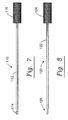
- Fig. 7 depicts a cervical osteotone 110 that may also be inserted through main sheath 30 if chiseling of a vertebrae is required at any stage of the procedure.
- Osteotone 110 includes a solid rod 112 having a chisel edge 114 formed in its leading end and a knurled base member 116 fixedly secured to its proximal end.
- the overall length of osteotone 110 is 125 mm; the length of rod 112 is 105 mm.
- the lateral extent of chisel edge 114 is 2.3mm so that the tool is easily insertable through the bore of the main sheath.
- a novel cervical cureet or scoop member 120 is depicted in Fig. 8; its rod part 122 and knurled base 124 have the same dimensions as the corresponding parts of the osteotone of Fig. 7.
- a scoop means 126 is formed in the leading end of rod 122; it has the same construction as a conventional scoop means of the type used in non-arthroscopic surgery, but is only 2.2mm in length. Cureet 120 is employed to scoop up the bone fragments created by bone chisel 110.
- the dimensions disclosed herein are believed to be quite critical although small deviations therefrom still fall within the scope of this important invention.
- the dimensions allow cervical discectomy to be performed by arthroscopic instruments.
- the inside and outside diameters of the dilator tubes and the outside diameters of the members insertable through the main sheath 30 are critical because they enable the arthroscopic procedures disclosed herein.
Abstract
Description
- This invention relates to arthroscopic surgical instruments. More particularly, it relates to miniature tools having utility in cervical discectomy.
- Neck pain is sometimes caused by the pressure of a ligament bearing against the spinal cord. The pressure can be surgically relieved by debulking, i.e., removing some of the nucleus beneath the ligament so that the ligament can return to its normal position.
- Nucleus debulking has heretofore been performed conventionally, i.e., a relatively large incision is made and the surgeon cuts through the membrane that overlies the ligament and through the ligament in order to reach the nucleus. The nucleus is cut and sufficient amounts thereof are removed to thereby remove the pressure that was the source of the pain.
- The tool usually employed to debulk the nucleus is known as a punch tool because it operates something like a paper punch, i.e., a shearing action accomplishes the desired cutting. More particularly, a typical punch tool has an elongate neck and the shearing mechanism is positioned at the distal end of that neck. A pair of handle members at the proximal end of the neck are squeezed by the surgeon and the squeezing action causes a first part of the shearing mechanism to slide with respect to a stationary second part of that mechanism, and nucleus matter between said parts is sheared from the main body of nucleus matter.
- The cervical discectomy punches of the type just described operate in a batch mode, i.e., they shear a single piece of tissue for each entry to the surgical site through an incision. After each shearing action, the punch must be withdrawn, an irrigation tool must be inserted to irrigate the site and place the sheared piece of nucleus into suspension, the irrigation tool must be withdrawn, a suction tool must be inserted to vacuum the irrigation fluid and the sheared piece, the suction tool must be withdrawn, and the punch inserted for another shearing action. Thus, a surgeon might be required to make dozens of entries and exits through an incision in the course of a surgical procedure when using a conventional, one bite punch instrument. Such multiple entries, exits, and re-entries obviously extend the time required to perform the surgical procedure, and tire the surgeon and surgical assistants.
- WO-A-89/01797 discloses a cervical discectomy apparatus comprising a guide wire to be inserted into the body through an incision therein, a push knob having a leading end and forming a first bore receiving the guide wire, and an internally threaded second bore, a set screw threadedly engaging the second bore and bearing against the guide wire received within the first bore when the set screw is advanced; a first dilator including a first tube of predetermined length, and a base secured to a proximal end of the first tube, the first tube and the base thereof forming a first common bore; and a second dilator, including a second tube of a predetermined length greater than the predetermined length of the first tube, a base secured to a proximal end of the second tube, the second tube and the base thereof forming a second common bore, the second tube having an outside diameter less than the diameter of the first common bore to be telescopically received by the first common bore.
- It is well known that arthroscopic surgical techniques require much smaller incisions and thus permit much faster patient recovery, thereby reducing the length of hospital stays and saving the expenses associated therewith, but arthroscopic tools capable of performing cervical discectomys do not appear in the prior art.
- The prior art, when considered as a whole, neither teaches nor suggests to those of ordinary skill in this field how the conventional punch could be improved, or how the debulking procedure could be performed arthroscopically.
- A novel set of miniature tools is provided for use by arthroscopic surgeons so that cervical discectomy can be performed arthroscopically for the first time.
- A first tool enables the physician to properly set a guide wire, known as a K wire after the first initial of its inventor's name, in the nucleus to be debulked. The K wire guides all of the instruments used subsequently in the surgical procedure to the site of the procedure. Heretofore, arthroscopic surgeons had no means for facilitation of K wire insertion between vertebrae.
- A second and third tool are provided to facilitate the initial dilation of the arthroscopic incision; moreover, the second tool is the main sheath through which all other tools are inserted throughout the course of the surgical procedure and also serves as the irrigation tool so that the operation site can be irrigated with saline solution as needed.
- A fourth tool is a ligament cutter; it is inserted through the bore of the main sheath after the third tool has been removed therefrom and said fourth tool performs the function its name expresses. More particularly, it cuts through the membrane that overlies the ligament and it further cuts a passageway through the ligament to expose the nucleus material thereunder.
- The set further includes a novel punch tool having a continuous suction port. The novel punch tool enables the physician to complete an entire debulking procedure, i.e., to perform repeated shearing actions, with a single insertion through an incision. The punch is inserted a single time, and the physician squeezes the handle members thereof as many times as needed so that the shearing members slice off as many pieces of nucleus material as required. The pieces of excised matter are continuously removed from the site by a continuous suction that withdraws irrigation fluid and surgical debris from the site. The suction means is provided in the form of an elongate suction bore that is formed in the neck of the punch; a suction port to which a cannula is releasably secured is positioned at the proximal end of the suction bore, and an opposite end of the cannula is detachably secured to a collection tank that is in fluid communication with a source of negative pressure. Suitable means are provided so that the physician can control the flow rate of the irrigation fluid through the suction bore.
- An arthroscopic cervical osteotone, an arthroscopic cervical cureet, a batch-type nucleus extractor, and a second type of cureet are also disclosed; all of these tools are insertable through the main sheath as and if needed. The second type of cureet tool has a handle arrangement like the novel continuous suction punch to facilitate its use.
- Thus it is apparent that the primary object of this invention is to provide arthroscopic surgeons with the tools they need to perform cervical discectomys.
- A more specific object is to provide a continuous suction punch to facilitate performance of arthroscopic procedures.
- These and other important objects, features and advantages of the invention will become apparent as this description proceeds.
- The invention accordingly comprises the features of construction, combination of elements and arrangement of parts that will be exemplified in the construction hereinafter set forth, and the scope of the invention will be indicated in the claims.
- The invention provides a cervical discectomy apparatus of the type disclosed in WO-A-89/01797 with the characterizing features of claim 1.
- Further features of the apparatus according to the invention are defined in the dependent claims.
- For a fuller understanding of the nature and objects of the invention, reference should be made to the following detailed description, taken in connection with the accompanying drawings, in which:
- Fig. 1 is a side elevational view of a novel K-wire push knob showing a length of K-wire retained therewithin;
- Fig. 2 is a side elevational view of a novel dilator tube having a water port;
- Fig. 3 is a side elevational view of a novel dilator tube;
- Fig. 4 is a side elevational view showing the tubes of Figs. 2 and 3 in their assembled configuration;
- Fig. 5 is a side elevational view of a novel ligament cutter;
- Fig. 6 is a side elevational view of the novel cervical continuous suction punch;
- Fig. 7 is a side elevational view of a novel cervical osteotone member; and
- Fig. 8 is a side elevational view of a novel cervical cureet;
-
- Similar reference numerals refer to similar parts throughout the several views of the drawings.
- Referring first to Fig. 1, there it will be seen that the novel K wire push knob is denoted 10 as a whole; the K wire is denoted 12. The
proximal end 14 ofK wire 12 is received withinbore 16 that is formed inpush knob 10. More particularly, the push knob includes aboss 18 and aknurled base 20;bore 16 extends the entire length of the boss and part of the length of the base as shown. Aset screw 22 having a knurled head screw threadedly engages an internally threaded radial bore formed in a reduceddiameter part 21 ofbase 20, said radial bore intersectingbore 16 so that the leading end of the set screw bears against the K wire when the set screw is advanced to releasably retain the guide wire withinbore 16. - After the arthroscopic incision has been made, the push knob is grasped by the physician and the distal end of the K wire is inserted into the ligament at the point where the underlying nucleus is to be debulked. The
push knob 10 is then removed from the K wire by loosening setscrew 22; penetration of the distal end of the K wire into the ligament retains it in position throughout the remainder of the surgical procedure. -
K wire 12 is preferably about 140mm in length, and the overall length ofpush knob 10 is 24mm. The reduceddiameter part 21 ofbase 20 is 8mm in length and the balance ofbase 20 is 12mm in length. - The incision is then dilated in a novel way. The
dilator tube 30 of Fig. 2 and thedilator tube 50 of Fig. 3 are releasably coupled together as a preparatory step to the dilation. Once coupled together, they are threaded over the K wire so that they are properly positioned. More particularly,tubular part 52 ofdilator tube 50 is slidably, i.e., telescopically, inserted into the hollow bore of thetubular part 32 ofdilator tube 30. The resulting assembly is depicted in Fig. 4 and this assembly is guided to the site by the K wire, i.e., the bore oftubular part 52 axially receives said K wire. Note that thedistal end 54 oftubular part 52 is tapered and extends beyond thedistal end 34 oftubular part 32. Note further that theproximal end 36 ofbase 38 oftube 30 is slidably received withincircular recess 56 formed inknurled base 58 oftube 50 and thatboss 59 ofbase 58 is slidably received within a complementally formedrecess 40 formed inbase 38 oftube 30. It should be noted thatboss 59 extends from a bottom wall ofrecess 56. This provides a double lock betweentubes - The tapered
distal end 54 oftube 50 performs the initial dilation; the taper is provided to avoid tearing the ligament as it passes through. Aftertube 50 has been advanced, thentube 30 is similarly advanced, i.e., it is advanced to the left as denoted by the directional arrow 42 in Fig. 4. This further dilates the incision. -
Tube 30 further includes awater port 44 having an inlet means adapted to be engaged by a cannula, not shown; the opposite end of the cannula is detachably secured to a source of saline solution under positive pressure. Suitable valving means are provided so that the physician can control the flow rate of saline solution to port 44.Port 44 is in open fluid communication withbore 46 oftubular part 32 so that saline solution flowing from the source thereof is delivered to the site of the surgical procedure under the direction and control of the surgeon. - After
dilator tube 30 has been advanced as indicated by directional arrow 42 to complete the dilation of the incision,dilator tube 50 is then slidingly decoupled therefrom and withdrawn.Dilator tube 30 is then used as the main sheath through thebore 46 of which other instruments are inserted as the surgical procedure progresses, i.e.,main sheath 30 remains in position, as doesK wire 12, until the surgical process of debulking the disc is undertaken. - The inside diameter of
main sheath 30, i.e., the diameter ofbore 46, is 2.5mm, and the outside diameter ofsheath 30 is 3mm. The overall length ofmain sheath 30 is 81mm. The length oftubular part 52 ofdilator tube 50 is 92mm, including the 10mm length ofboss 59.Recess 40 formed inbase 38 ofmain sheath 30 is also 10mm in depth to receive saidboss 59. - The
ligament cutter 60 of Fig. 5 is next employed; it has an overall length of 104mm and it includes atubular part 62, having an outside diameter of 2.4mm, saidtubular part 62 having a leadingend 64; leadingend 64 has a cookie cutter-style cutting edge.Tool 60 further includes a proximal end having a 10mm inlength knurled base 66, a boss 68 having about the same length, and abore 70 for receiving the K wire. Theligament cutter 60 is used by threading it onto the K wire, i.e., by aligning said wire withbore 70 at the leading end of the cutter and by advancing the cutter throughbore 46 ofmain sheath 30 toward the surgical site. The physician then oscillates thecutter 60 about its longitudinal axis of rotation as indicated by double-headed directional arrow 72; this action causes cuttingedge 64 to slice through the membrane overlying the ligament and continued oscillation and advancement of the cutter enable it to cut a passageway through the ligament and into the underlying nucleus. The cutter and K-wire are withdrawn after the passageway has been formed, butmain sheath 30 remains in position. - Debulking of the nucleus may now be undertaken; the preferred tool for performing the debulking procedure is depicted in Fig. 6 and is denoted as a whole by the
reference numeral 80. - This illustrative embodiment of the novel cervical
continuous suction punch 80 includes anelongate neck 82 having a pair of shearing members collectively denoted 84 at the distal end thereof. Shearingmembers 84 are known in larger punch tools of the type used in conventional, i.e., non-arthroscopic surgery, and thus their construction need not be described. A novel handle means 86 in the form of a pair ofhandle members neck 82 at the proximal end thereof and said handle members depend therefrom; the members are pivotally mounted aboutpivot point 89, andmember 90 has a thumb-receivingloop 91. Astrip 92 of spring steel or other suitable material biases handlemembers arrow 93, i.e., the physician must overcome the bias to squeeze said handle members toward one another.Shear members 84 are spaced apart from one another whenpunch 10 is in repose and ultimately converge toward one another when said handle members are squeezed; a diverging motion precedes the converging motion, but, again, the particular operation of the shearing members is well known and need not be described here. - A
coil spring 94 or other suitable bias means is employed to urge thehandle members arrows 95; thus,spring steel member 92 andcoil spring member 94 are first and second bias means, respectively, that oppose one another. The strength of the opposing bias means is substantially equal. This unique arrangement of parts removes play from the handle means 86 and insures that thehandle members - A bore 96 is formed in
neck 82 and provides fluid communication betweenshears 84 andsuction port 98 at the proximal end ofpunch tool 80.Bore 96 extends intoport 98 as shown;port 98 provides a mounting means to which a first end of a cannula, not shown, or other suitable flexible tube means is detachably secured when thenovel punch 80 is in use. The second end of the cannula is detachably secured to an unillustrated collection receptacle that is in fluid communication with an undepicted source of negative pressure. - The site of the surgical procedure is irrigated during the nucleus-shearing process by causing irrigation fluid to flow into
water port 44 inmain sheath 30; the inside diameter of the main sheath is sufficient to receiveneck 82 ofpunch tool 80 and to allow sufficient space thereabout to allow the irrigation fluid to flow freely to the surgical site. Thus, as each piece of nucleus is sheared byshears 84, releasing the squeezing motion imparted to handlemembers - Suitable means are provided to permit the physician to control the amount of negative pressure supplied to
port 98 and thus the flow rate of irrigation fluid and surgical debris flowing therethrough in the direction ofarrow 100. - Thus, a single insertion of
neck 82 through the bore ofmain sheath 30 is the only insertion needed to complete the entire debulking procedure. Irrigation fluid is introduced throughwater port 44 throughout the entire debulking procedure, and the suction applied toport 98 is similarly continuous throughout said procedure. -
Neck 82 is preferably about 105mm in length, exclusive ofhandle 86; saidhandle 86 has a length, measured from theneck 82 to the lowermost end ofhandle member 88, of about 85mm. The outside diameter ofneck 82 is 2.5mm, and the length of the movable part of theshear members 84 is 4mm. - Fig. 7 depicts a
cervical osteotone 110 that may also be inserted throughmain sheath 30 if chiseling of a vertebrae is required at any stage of the procedure.Osteotone 110 includes asolid rod 112 having achisel edge 114 formed in its leading end and aknurled base member 116 fixedly secured to its proximal end. The overall length ofosteotone 110 is 125 mm; the length ofrod 112 is 105 mm. The lateral extent ofchisel edge 114 is 2.3mm so that the tool is easily insertable through the bore of the main sheath. - A novel cervical cureet or
scoop member 120 is depicted in Fig. 8; itsrod part 122 andknurled base 124 have the same dimensions as the corresponding parts of the osteotone of Fig. 7. A scoop means 126 is formed in the leading end ofrod 122; it has the same construction as a conventional scoop means of the type used in non-arthroscopic surgery, but is only 2.2mm in length.Cureet 120 is employed to scoop up the bone fragments created bybone chisel 110. - All of the dimensions disclosed herein are believed to be quite critical although small deviations therefrom still fall within the scope of this important invention. The dimensions allow cervical discectomy to be performed by arthroscopic instruments. The inside and outside diameters of the dilator tubes and the outside diameters of the members insertable through the
main sheath 30 are critical because they enable the arthroscopic procedures disclosed herein. - This invention is clearly new and useful. Moreover, it was not obvious to those of ordinary skill in this art at the time it was made, in view of the prior art considered as a whole as required by law.
Claims (3)
- A cervical discectomy apparatus comprising(a) a guide wire (12) to be inserted into the body through an incision therein,(b) a push knob (10) having a leading end (21) and forming a first bore (16) receiving the guide wire, and an internally threaded second bore, a set screw (22) threadedly engageing the second bore and bearing against the guide wire (12) received within the first bore (16) when the set screw (22) is advanced;(c) a first dilator (30) including a first tube (32) of predetermined length, and a base (38) secured to a proximal end of the first tube (32), the first tube (32) and the base (38) thereof forming a first common bore (46); and(d) a second dilator (50), including a second tube (52) of a predetermined length greater than the predetermined length of the first tube (32), a base (58) secured to a proximal end of the second tube (52), the second tube (52) and the base (58) thereof forming a second common bore, the second tube (52) having an outside diameter less than the diameter of the first common bore (46) to be telescopically received by the first common bore (46) characterized by a water port (44) formed in the base (38) of the first tube and communicating with the first common bore (46) and the outside surface of the second tube (52) when the second tube (52) is received by the first common bore (46) thereby forming an irrigation passageway in an axial direction between the first and the second tubes (32; 52).
- The cervical discectomy apparatus of claim 1, characterized by an arthroscopic ligament cutter (60), including a tubular part (62) with a sharp distal end (64) for cutting tissue upon rotation of the tubular part (62) which has an outside diameter less than the diameter of the first common bore (46) to be telescopically received by the first tube (32), a knurled cutter base (66) fixedly secured to the proximal end of the tubular part (62) for facilitating manual rotation thereof, and a boss (68) secured to a distal end of the cutter base (66), the tubular part (62), the cutter boss (68), and the cutter base (66) forming a third common bore (70) to slidingly receive the guide wire (12) therein positioning and guiding the ligament cutter (60).
- The cervical discectomy apparatus of claim 2 characterized in that base (38) of the first tube in the proximal end (36) thereof forms a recess (40) of predetermined depth and predetermined diameter, that the base (58) of the second tube at a distal end thereof forms an annular recess (56) of predetermined depth and predetermined diameter, and that a boss (59) of predetermined diameter extends from the distal end of the base (58) of the second tube, the boss (59) being circumscribed by the annular recess (56) and being configured and dimensioned to be slidingly received within the annular recess (40) formed in the proximal end of the base (38) of the first tube to form a first lock, the proximal end of the first tube base (38) being slidingly received within the annular recess (56) formed in the base (58) of the second tube to form a second lock when the first tube (32) slidingly receives the second tube (52), whereby a double lock is provided to lock the bases (38; 58) of the first and second tubes together.
Priority Applications (1)
| Application Number | Priority Date | Filing Date | Title |
|---|---|---|---|
| EP01105835A EP1101471B1 (en) | 1991-09-12 | 1992-09-14 | Cervical discectomy instruments |
Applications Claiming Priority (3)
| Application Number | Priority Date | Filing Date | Title |
|---|---|---|---|
| US758013 | 1991-09-12 | ||
| US07/758,013 US5269797A (en) | 1991-09-12 | 1991-09-12 | Cervical discectomy instruments |
| PCT/US1992/007735 WO1993004652A1 (en) | 1991-09-12 | 1992-09-14 | Cervical dissectomy instruments |
Related Child Applications (1)
| Application Number | Title | Priority Date | Filing Date |
|---|---|---|---|
| EP01105835A Division EP1101471B1 (en) | 1991-09-12 | 1992-09-14 | Cervical discectomy instruments |
Publications (3)
| Publication Number | Publication Date |
|---|---|
| EP0603313A1 EP0603313A1 (en) | 1994-06-29 |
| EP0603313A4 EP0603313A4 (en) | 1995-12-06 |
| EP0603313B1 true EP0603313B1 (en) | 2001-12-12 |
Family
ID=25050117
Family Applications (2)
| Application Number | Title | Priority Date | Filing Date |
|---|---|---|---|
| EP01105835A Expired - Lifetime EP1101471B1 (en) | 1991-09-12 | 1992-09-14 | Cervical discectomy instruments |
| EP92920314A Expired - Lifetime EP0603313B1 (en) | 1991-09-12 | 1992-09-14 | Cervical discectomy instruments |
Family Applications Before (1)
| Application Number | Title | Priority Date | Filing Date |
|---|---|---|---|
| EP01105835A Expired - Lifetime EP1101471B1 (en) | 1991-09-12 | 1992-09-14 | Cervical discectomy instruments |
Country Status (9)
| Country | Link |
|---|---|
| US (2) | US5269797A (en) |
| EP (2) | EP1101471B1 (en) |
| JP (1) | JPH07502419A (en) |
| AT (1) | ATE210407T1 (en) |
| AU (1) | AU663338B2 (en) |
| CA (1) | CA2118811A1 (en) |
| DE (2) | DE69233382T2 (en) |
| RU (1) | RU2121813C1 (en) |
| WO (1) | WO1993004652A1 (en) |
Families Citing this family (235)
| Publication number | Priority date | Publication date | Assignee | Title |
|---|---|---|---|---|
| US5171279A (en) * | 1992-03-17 | 1992-12-15 | Danek Medical | Method for subcutaneous suprafascial pedicular internal fixation |
| FR2714285B1 (en) * | 1993-12-24 | 1996-03-15 | Impact | Device for performing a percutaneous nucleotomy. |
| US5643229A (en) * | 1994-07-22 | 1997-07-01 | Sinaiko; Edwin S. | Suction tube apparatus |
| US5693064A (en) * | 1994-11-04 | 1997-12-02 | Arnold; James E. | Dermal punch for hair transplantation and methods |
| CA2159685C (en) * | 1994-10-07 | 2007-07-31 | Scott W. Larsen | Endoscopic surgical instruments useful for spinal procedures |
| JP3678752B2 (en) * | 1994-10-31 | 2005-08-03 | ボストン・サイエンティフィック・コーポレーション | Biopsy needle |
| US5879365A (en) * | 1995-04-04 | 1999-03-09 | United States Surgical Corporation | Surgical cutting apparatus |
| US5873886A (en) * | 1995-04-04 | 1999-02-23 | United States Surgical Corporation | Surgical cutting apparatus |
| US5693011A (en) * | 1995-04-27 | 1997-12-02 | Surgical Dynamics, Inc. | Surgical suction cutting instrument |
| DE19515626C2 (en) * | 1995-04-28 | 2000-04-06 | Wolf Gmbh Richard | Instrument for positioning at least one working sleeve |
| US5857982A (en) * | 1995-09-08 | 1999-01-12 | United States Surgical Corporation | Apparatus and method for removing tissue |
| US5817034A (en) * | 1995-09-08 | 1998-10-06 | United States Surgical Corporation | Apparatus and method for removing tissue |
| US5792044A (en) | 1996-03-22 | 1998-08-11 | Danek Medical, Inc. | Devices and methods for percutaneous surgery |
| US7198598B2 (en) * | 1996-03-22 | 2007-04-03 | Warsaw Orthopedic, Inc. | Devices and methods for percutaneous surgery |
| US6679833B2 (en) | 1996-03-22 | 2004-01-20 | Sdgi Holdings, Inc. | Devices and methods for percutaneous surgery |
| ES2224228T3 (en) * | 1996-03-22 | 2005-03-01 | Sdgi Holdings, Inc. | DEVICE FOR PERCUTANEOUS SURGERY. |
| DE69735146T2 (en) * | 1996-05-09 | 2006-09-28 | Olympus Corporation | Surgical tool for holding a cavity |
| US6733496B2 (en) | 2001-06-06 | 2004-05-11 | Oratec Interventions, Inc. | Intervertebral disc device employing flexible probe |
| US6726685B2 (en) * | 2001-06-06 | 2004-04-27 | Oratec Interventions, Inc. | Intervertebral disc device employing looped probe |
| US6126682A (en) | 1996-08-13 | 2000-10-03 | Oratec Interventions, Inc. | Method for treating annular fissures in intervertebral discs |
| US7069087B2 (en) * | 2000-02-25 | 2006-06-27 | Oratec Interventions, Inc. | Apparatus and method for accessing and performing a function within an intervertebral disc |
| US6832997B2 (en) | 2001-06-06 | 2004-12-21 | Oratec Interventions, Inc. | Electromagnetic energy delivery intervertebral disc treatment devices |
| TW375522B (en) * | 1996-10-24 | 1999-12-01 | Danek Medical Inc | Devices for percutaneous surgery under direct visualization and through an elongated cannula |
| AU7178698A (en) | 1996-11-15 | 1998-06-03 | Advanced Bio Surfaces, Inc. | Biomaterial system for in situ tissue repair |
| US6068630A (en) * | 1997-01-02 | 2000-05-30 | St. Francis Medical Technologies, Inc. | Spine distraction implant |
| US5976146A (en) * | 1997-07-11 | 1999-11-02 | Olympus Optical Co., Ltd. | Surgical operation system and method of securing working space for surgical operation in body |
| JPH1176247A (en) * | 1997-07-11 | 1999-03-23 | Olympus Optical Co Ltd | Surgical operation system |
| US6175758B1 (en) | 1997-07-15 | 2001-01-16 | Parviz Kambin | Method for percutaneous arthroscopic disc removal, bone biopsy and fixation of the vertebrae |
| US5938685A (en) * | 1997-09-05 | 1999-08-17 | Boston Scientific Corporation | Locking handle for surgical instruments |
| US6551253B2 (en) | 1997-09-12 | 2003-04-22 | Imagyn Medical Technologies | Incisional breast biopsy device |
| US6383145B1 (en) | 1997-09-12 | 2002-05-07 | Imagyn Medical Technologies California, Inc. | Incisional breast biopsy device |
| US6142955A (en) | 1997-09-19 | 2000-11-07 | United States Surgical Corporation | Biopsy apparatus and method |
| JP2002506672A (en) | 1998-03-19 | 2002-03-05 | オーレイテック インターヴェンションズ インコーポレイテッド | Catheter for delivering energy to the surgical site |
| US7799036B2 (en) | 1998-08-20 | 2010-09-21 | Zimmer Spine, Inc. | Method and apparatus for securing vertebrae |
| US6187000B1 (en) | 1998-08-20 | 2001-02-13 | Endius Incorporated | Cannula for receiving surgical instruments |
| US7641670B2 (en) | 1998-08-20 | 2010-01-05 | Zimmer Spine, Inc. | Cannula for receiving surgical instruments |
| WO2000038574A1 (en) | 1998-12-23 | 2000-07-06 | Nuvasive, Inc. | Nerve surveillance cannulae systems |
| US20050203334A1 (en) * | 1999-01-26 | 2005-09-15 | Lonky Neal M. | Vacuum instrument for laparotomy procedures |
| US6641575B1 (en) * | 1999-01-26 | 2003-11-04 | Neal M. Lonky | Surgical vacuum instrument for retracting, extracting, and manipulating tissue |
| CA2363254C (en) * | 1999-03-07 | 2009-05-05 | Discure Ltd. | Method and apparatus for computerized surgery |
| US6159179A (en) * | 1999-03-12 | 2000-12-12 | Simonson; Robert E. | Cannula and sizing and insertion method |
| ES2222713T3 (en) * | 1999-06-16 | 2005-02-01 | Joimax Gmbh | DEVICE TO UNCOMPRESS HERNIAS OF INTERVERTEBRAL DISCS. |
| US6575899B1 (en) | 1999-10-20 | 2003-06-10 | Sdgi Holdings, Inc. | Methods and instruments for endoscopic interbody surgical techniques |
| US6214010B1 (en) * | 1999-11-04 | 2001-04-10 | Thompson Surgical Instruments, Inc. | Rongeur surgical instrument |
| EP1237472A4 (en) | 1999-11-24 | 2008-04-30 | Nuvasive Inc | Electromyography system |
| US8409214B2 (en) * | 2009-01-22 | 2013-04-02 | Meditech Development Incorporated | Portable regulated vacuum pump for medical procedures |
| US8915894B1 (en) | 2000-01-24 | 2014-12-23 | Meditech Development Incorporated | Vacuum cup for delivery of agents during vacuum treatment |
| DE10003050C2 (en) * | 2000-01-25 | 2002-03-07 | Copf Jun | Surgical dilatation instrument and spacer for use with such |
| JP2004516040A (en) | 2000-06-30 | 2004-06-03 | リトラン、スティーブン | Multi-shaft coupling device and method |
| US7985247B2 (en) | 2000-08-01 | 2011-07-26 | Zimmer Spine, Inc. | Methods and apparatuses for treating the spine through an access device |
| US7056321B2 (en) | 2000-08-01 | 2006-06-06 | Endius, Incorporated | Method of securing vertebrae |
| US6712773B1 (en) | 2000-09-11 | 2004-03-30 | Tyco Healthcare Group Lp | Biopsy system |
| US6692434B2 (en) | 2000-09-29 | 2004-02-17 | Stephen Ritland | Method and device for retractor for microsurgical intermuscular lumbar arthrodesis |
| US7166073B2 (en) | 2000-09-29 | 2007-01-23 | Stephen Ritland | Method and device for microsurgical intermuscular spinal surgery |
| JP2004522469A (en) * | 2000-11-13 | 2004-07-29 | ボエム・フランク・エイッチ・ジュニア | Lumbar interbody fusion device and method |
| JP2005506098A (en) * | 2001-01-29 | 2005-03-03 | デピュイ スパイン、インコーポレイテッド | Spinal pedicle screw placement retractor and method |
| US6929606B2 (en) | 2001-01-29 | 2005-08-16 | Depuy Spine, Inc. | Retractor and method for spinal pedicle screw placement |
| US6638276B2 (en) | 2001-06-06 | 2003-10-28 | Oratec Interventions, Inc. | Intervertebral disc device employing prebent sheath |
| WO2003005887A2 (en) | 2001-07-11 | 2003-01-23 | Nuvasive, Inc. | System and methods for determining nerve proximity, direction, and pathology during surgery |
| EP2481338A3 (en) | 2001-09-25 | 2012-09-05 | Nuvasive, Inc. | System for performing surgical procedures and assessments |
| ATE495709T1 (en) | 2001-09-28 | 2011-02-15 | Stephen Ritland | CONNECTING ROD FOR A POLYAXIAL SYSTEM WITH SCREW OR HOOK |
| US6916330B2 (en) * | 2001-10-30 | 2005-07-12 | Depuy Spine, Inc. | Non cannulated dilators |
| US7008431B2 (en) | 2001-10-30 | 2006-03-07 | Depuy Spine, Inc. | Configured and sized cannula |
| US7824410B2 (en) | 2001-10-30 | 2010-11-02 | Depuy Spine, Inc. | Instruments and methods for minimally invasive spine surgery |
| WO2003073908A2 (en) * | 2002-02-20 | 2003-09-12 | Stephen Ritland | Pedicle screw connector apparatus and method |
| US20030187431A1 (en) * | 2002-03-29 | 2003-10-02 | Simonson Robert E. | Apparatus and method for targeting for surgical procedures |
| US6966910B2 (en) | 2002-04-05 | 2005-11-22 | Stephen Ritland | Dynamic fixation device and method of use |
| WO2003094699A2 (en) * | 2002-05-08 | 2003-11-20 | Stephen Ritland | Dynamic fixation device and method of use |
| US7004947B2 (en) | 2002-06-24 | 2006-02-28 | Endius Incorporated | Surgical instrument for moving vertebrae |
| US7582058B1 (en) | 2002-06-26 | 2009-09-01 | Nuvasive, Inc. | Surgical access system and related methods |
| US6793678B2 (en) | 2002-06-27 | 2004-09-21 | Depuy Acromed, Inc. | Prosthetic intervertebral motion disc having dampening |
| US9259144B2 (en) * | 2002-07-11 | 2016-02-16 | Nuvasive, Inc. | Surgical access system and related methods |
| US6648888B1 (en) | 2002-09-06 | 2003-11-18 | Endius Incorporated | Surgical instrument for moving a vertebra |
| US7074226B2 (en) * | 2002-09-19 | 2006-07-11 | Sdgi Holdings, Inc. | Oval dilator and retractor set and method |
| US8137284B2 (en) | 2002-10-08 | 2012-03-20 | Nuvasive, Inc. | Surgical access system and related methods |
| AU2003272308A1 (en) * | 2002-10-25 | 2004-05-25 | Endius Incorporated | Apparatus and methods for shielding body structures during surgery |
| US20040106997A1 (en) * | 2002-11-01 | 2004-06-03 | Lieberson Robert E. | Apparatus and method for creating a surgical channel |
| US7691057B2 (en) | 2003-01-16 | 2010-04-06 | Nuvasive, Inc. | Surgical access system and related methods |
| US7090680B2 (en) * | 2003-02-12 | 2006-08-15 | Bonati Alfred O | Method for removing orthopaedic hardware |
| US20040158257A1 (en) * | 2003-02-12 | 2004-08-12 | Bonati Alfred O. | Extractor tube for removing orthopaedic hardware |
| EP1596738A4 (en) * | 2003-02-25 | 2010-01-20 | Stephen Ritland | Adjustable rod and connector device and method of use |
| US7819801B2 (en) | 2003-02-27 | 2010-10-26 | Nuvasive, Inc. | Surgical access system and related methods |
| US7641659B2 (en) * | 2003-03-13 | 2010-01-05 | Zimmer Spine, Inc. | Spinal access instrument |
| US7465304B1 (en) | 2003-04-14 | 2008-12-16 | Spine Design, Inc. | Anterior cervical facet discectomy surgery kit and method for its use |
| US7645232B2 (en) | 2003-05-16 | 2010-01-12 | Zimmer Spine, Inc. | Access device for minimally invasive surgery |
| WO2004110247A2 (en) | 2003-05-22 | 2004-12-23 | Stephen Ritland | Intermuscular guide for retractor insertion and method of use |
| US7811303B2 (en) * | 2003-08-26 | 2010-10-12 | Medicine Lodge Inc | Bodily tissue dilation systems and methods |
| WO2005030318A1 (en) | 2003-09-25 | 2005-04-07 | Nuvasive, Inc. | Surgical access system and related methods |
| US7905840B2 (en) * | 2003-10-17 | 2011-03-15 | Nuvasive, Inc. | Surgical access system and related methods |
| US20050090822A1 (en) * | 2003-10-24 | 2005-04-28 | Dipoto Gene | Methods and apparatus for stabilizing the spine through an access device |
| US7655012B2 (en) | 2003-10-02 | 2010-02-02 | Zimmer Spine, Inc. | Methods and apparatuses for minimally invasive replacement of intervertebral discs |
| US20050090899A1 (en) * | 2003-10-24 | 2005-04-28 | Dipoto Gene | Methods and apparatuses for treating the spine through an access device |
| US7731737B2 (en) * | 2003-10-24 | 2010-06-08 | Zimmer Spine, Inc. | Methods and apparatuses for fixation of the spine through an access device |
| US7905907B2 (en) | 2003-10-21 | 2011-03-15 | Theken Spine, Llc | Internal structure stabilization system for spanning three or more structures |
| US7645282B2 (en) * | 2003-11-20 | 2010-01-12 | Osseus, Llc | Method and device for cutting surgical wire or cable |
| US8038611B2 (en) | 2003-12-18 | 2011-10-18 | Depuy Spine, Inc. | Surgical methods and surgical kits |
| US20050137600A1 (en) * | 2003-12-23 | 2005-06-23 | Jacobs Andrew M. | Articular cartilage repair implant delivery device and method of use |
| DE102004006521A1 (en) * | 2004-02-10 | 2005-09-08 | Horst Drs. Dekkers | Set of surgical instruments for spine surgery |
| US7909843B2 (en) | 2004-06-30 | 2011-03-22 | Thompson Surgical Instruments, Inc. | Elongateable surgical port and dilator |
| US20060004398A1 (en) * | 2004-07-02 | 2006-01-05 | Binder Lawrence J Jr | Sequential dilator system |
| US7434325B2 (en) | 2004-07-26 | 2008-10-14 | Warsaw Orthopedic, Inc. | Systems and methods for determining optimal retractor length in minimally invasive procedures |
| US9387313B2 (en) | 2004-08-03 | 2016-07-12 | Interventional Spine, Inc. | Telescopic percutaneous tissue dilation systems and related methods |
| JP5164571B2 (en) * | 2004-08-03 | 2013-03-21 | インターヴェンショナル スパイン インコーポレイテッド | Percutaneous tissue expansion system and related methods |
| US20060052812A1 (en) * | 2004-09-07 | 2006-03-09 | Michael Winer | Tool for preparing a surgical site for an access device |
| EP1799130A1 (en) * | 2004-09-14 | 2007-06-27 | Uromedica, Inc. | Implantation tool for adjustable implantable genitourinary device |
| US7455639B2 (en) | 2004-09-20 | 2008-11-25 | Stephen Ritland | Opposing parallel bladed retractor and method of use |
| US7666189B2 (en) * | 2004-09-29 | 2010-02-23 | Synthes Usa, Llc | Less invasive surgical system and methods |
| US9622732B2 (en) | 2004-10-08 | 2017-04-18 | Nuvasive, Inc. | Surgical access system and related methods |
| US9055981B2 (en) | 2004-10-25 | 2015-06-16 | Lanx, Inc. | Spinal implants and methods |
| US8241330B2 (en) | 2007-01-11 | 2012-08-14 | Lanx, Inc. | Spinous process implants and associated methods |
| US8007517B2 (en) * | 2004-10-25 | 2011-08-30 | Lanx, Inc. | Interspinous distraction devices and associated methods of insertion |
| WO2006049917A2 (en) * | 2004-10-29 | 2006-05-11 | Depuy Spine, Inc | Expandable ports and methods for minimally invasive surgery |
| US20060217664A1 (en) * | 2004-11-15 | 2006-09-28 | Hattler Brack G | Telescoping vascular dilator |
| US7569061B2 (en) | 2004-11-16 | 2009-08-04 | Innovative Spinal Technologies, Inc. | Off-axis anchor guidance system |
| US20060224044A1 (en) * | 2005-03-31 | 2006-10-05 | Depuy Spine, Inc. | Surgical retractors and methods of use |
| US20060241566A1 (en) * | 2005-04-11 | 2006-10-26 | Orthox, Llc | Nucleus Extraction from Spine Intervertebral Disc |
| US7427264B2 (en) * | 2005-04-22 | 2008-09-23 | Warsaw Orthopedic, Inc. | Instruments and methods for selective tissue retraction through a retractor sleeve |
| EP1906885B2 (en) | 2005-07-19 | 2019-01-16 | Warsaw Orthopedic, Inc. | Rod extension for extending fusion construct |
| US20070055259A1 (en) * | 2005-08-17 | 2007-03-08 | Norton Britt K | Apparatus and methods for removal of intervertebral disc tissues |
| WO2007038429A1 (en) | 2005-09-27 | 2007-04-05 | Endius, Inc. | Methods and apparatuses for stabilizing the spine through an access device |
| US8066730B2 (en) * | 2005-11-14 | 2011-11-29 | Scapa Flow, Llc | Medical dilator system or dilator device |
| US20070162062A1 (en) * | 2005-12-08 | 2007-07-12 | Norton Britt K | Reciprocating apparatus and methods for removal of intervertebral disc tissues |
| US7758501B2 (en) | 2006-01-04 | 2010-07-20 | Depuy Spine, Inc. | Surgical reactors and methods of minimally invasive surgery |
| US7918792B2 (en) * | 2006-01-04 | 2011-04-05 | Depuy Spine, Inc. | Surgical retractor for use with minimally invasive spinal stabilization systems and methods of minimally invasive surgery |
| US7981031B2 (en) | 2006-01-04 | 2011-07-19 | Depuy Spine, Inc. | Surgical access devices and methods of minimally invasive surgery |
| US7955257B2 (en) * | 2006-01-05 | 2011-06-07 | Depuy Spine, Inc. | Non-rigid surgical retractor |
| US8167899B2 (en) * | 2006-05-04 | 2012-05-01 | Warsaw Orthopedic, Inc. | Retractable stylet and cannula combination |
| US7842038B2 (en) | 2006-05-04 | 2010-11-30 | Warsaw Orthopedic, Inc. | Method for using retractable stylet and cannula combination to form an opening in bone |
| US20070265633A1 (en) * | 2006-05-11 | 2007-11-15 | Moon Jon K | Implement and method to extract nucleus from spine intervertebral disc |
| US8092536B2 (en) | 2006-05-24 | 2012-01-10 | Disc Dynamics, Inc. | Retention structure for in situ formation of an intervertebral prosthesis |
| US7959564B2 (en) | 2006-07-08 | 2011-06-14 | Stephen Ritland | Pedicle seeker and retractor, and methods of use |
| US8105382B2 (en) | 2006-12-07 | 2012-01-31 | Interventional Spine, Inc. | Intervertebral implant |
| US9232959B2 (en) | 2007-01-02 | 2016-01-12 | Aquabeam, Llc | Multi fluid tissue resection methods and devices |
| US9265532B2 (en) | 2007-01-11 | 2016-02-23 | Lanx, Inc. | Interspinous implants and methods |
| US8398640B2 (en) | 2007-03-23 | 2013-03-19 | John Riley Hawkins | Volume measuring intervertebral tool system and method |
| US20080255651A1 (en) * | 2007-04-12 | 2008-10-16 | Medtronic Vascular, Inc. | Telescoping Stability Sheath and Method of Use |
| US8900307B2 (en) | 2007-06-26 | 2014-12-02 | DePuy Synthes Products, LLC | Highly lordosed fusion cage |
| EP2205171B1 (en) | 2007-10-05 | 2016-03-23 | Synthes GmbH | Dilation system |
| CA2710142A1 (en) | 2008-01-17 | 2009-07-23 | Beat Lechmann | An expandable intervertebral implant and associated method of manufacturing the same |
| JP5506702B2 (en) | 2008-03-06 | 2014-05-28 | アクアビーム エルエルシー | Tissue ablation and cauterization by optical energy transmitted in fluid flow |
| WO2009124269A1 (en) | 2008-04-05 | 2009-10-08 | Synthes Usa, Llc | Expandable intervertebral implant |
| US20100023006A1 (en) * | 2008-07-23 | 2010-01-28 | Ellman Alan G | RF intervertebral disc surgical system |
| WO2010075555A2 (en) | 2008-12-26 | 2010-07-01 | Scott Spann | Minimally-invasive retroperitoneal lateral approach for spinal surgery |
| US9526620B2 (en) | 2009-03-30 | 2016-12-27 | DePuy Synthes Products, Inc. | Zero profile spinal fusion cage |
| CN102448392A (en) | 2009-03-31 | 2012-05-09 | 兰克斯股份有限公司 | Spinous process implants and associated methods |
| US9393129B2 (en) | 2009-12-10 | 2016-07-19 | DePuy Synthes Products, Inc. | Bellows-like expandable interbody fusion cage |
| US8486097B2 (en) * | 2010-02-04 | 2013-07-16 | Nico Corporation | Tissue cutting device |
| US8986334B2 (en) * | 2010-02-04 | 2015-03-24 | Nico Corporation | Tissue removal device with tissue grip |
| US8979860B2 (en) | 2010-06-24 | 2015-03-17 | DePuy Synthes Products. LLC | Enhanced cage insertion device |
| US9592063B2 (en) | 2010-06-24 | 2017-03-14 | DePuy Synthes Products, Inc. | Universal trial for lateral cages |
| WO2012003175A1 (en) | 2010-06-29 | 2012-01-05 | Synthes Usa, Llc | Distractible intervertebral implant |
| US8562610B2 (en) | 2010-07-13 | 2013-10-22 | Warsaw Orthopedic, Inc. | Compliant device and method for cutting an intervertebral disc |
| US9402732B2 (en) | 2010-10-11 | 2016-08-02 | DePuy Synthes Products, Inc. | Expandable interspinous process spacer implant |
| US9155503B2 (en) | 2010-10-27 | 2015-10-13 | Cadwell Labs | Apparatus, system, and method for mapping the location of a nerve |
| WO2012100211A2 (en) | 2011-01-20 | 2012-07-26 | Hansen Medical, Inc. | System and method for endoluminal and transluminal therapy |
| US20120197320A1 (en) * | 2011-01-28 | 2012-08-02 | Laser Spine Surgical Center, LLC | Foraminoplasty Device |
| US9445825B2 (en) | 2011-02-10 | 2016-09-20 | Wright Medical Technology, Inc. | Expandable surgical device |
| US8790406B1 (en) | 2011-04-01 | 2014-07-29 | William D. Smith | Systems and methods for performing spine surgery |
| US8834507B2 (en) | 2011-05-17 | 2014-09-16 | Warsaw Orthopedic, Inc. | Dilation instruments and methods |
| US10166018B2 (en) | 2011-08-19 | 2019-01-01 | Nuvasive, Inc. | Surgical retractor system and methods of use |
| US8753344B2 (en) * | 2011-09-23 | 2014-06-17 | Smith & Nephew, Inc. | Dynamic orthoscopic sensing |
| US11812923B2 (en) | 2011-10-07 | 2023-11-14 | Alan Villavicencio | Spinal fixation device |
| US9198765B1 (en) | 2011-10-31 | 2015-12-01 | Nuvasive, Inc. | Expandable spinal fusion implants and related methods |
| US9028522B1 (en) | 2011-11-15 | 2015-05-12 | Seaspine, Inc. | Tissue dilator and retractor system and method of use |
| EP2819599B1 (en) | 2012-02-29 | 2018-05-23 | Procept Biorobotics Corporation | Automated image-guided tissue resection and treatment |
| US9186444B2 (en) | 2012-05-07 | 2015-11-17 | Meditech Development Incorporated | Portable regulated pressure devices for medical procedures |
| US8940052B2 (en) | 2012-07-26 | 2015-01-27 | DePuy Synthes Products, LLC | Expandable implant |
| US20140067069A1 (en) | 2012-08-30 | 2014-03-06 | Interventional Spine, Inc. | Artificial disc |
| US9295401B2 (en) | 2012-11-27 | 2016-03-29 | Cadwell Laboratories, Inc. | Neuromonitoring systems and methods |
| US10231867B2 (en) | 2013-01-18 | 2019-03-19 | Auris Health, Inc. | Method, apparatus and system for a water jet |
| US9522070B2 (en) | 2013-03-07 | 2016-12-20 | Interventional Spine, Inc. | Intervertebral implant |
| US9277928B2 (en) | 2013-03-11 | 2016-03-08 | Interventional Spine, Inc. | Method and apparatus for minimally invasive insertion of intervertebral implants |
| US10098585B2 (en) | 2013-03-15 | 2018-10-16 | Cadwell Laboratories, Inc. | Neuromonitoring systems and methods |
| US10744035B2 (en) | 2013-06-11 | 2020-08-18 | Auris Health, Inc. | Methods for robotic assisted cataract surgery |
| US10426661B2 (en) | 2013-08-13 | 2019-10-01 | Auris Health, Inc. | Method and apparatus for laser assisted cataract surgery |
| US9788856B2 (en) | 2014-03-11 | 2017-10-17 | Stryker European Holdings I, Llc | Endoscopic surgical systems and methods |
| US10258228B2 (en) * | 2014-08-08 | 2019-04-16 | K2M, Inc. | Retraction devices, systems, and methods for minimally invasive spinal surgery |
| US11426290B2 (en) | 2015-03-06 | 2022-08-30 | DePuy Synthes Products, Inc. | Expandable intervertebral implant, system, kit and method |
| US10433793B1 (en) | 2015-03-27 | 2019-10-08 | Cadwell Laboratories, Inc. | Methods and systems for simultaneous review of brain activity and physical manifestations of users |
| US20160287279A1 (en) | 2015-04-01 | 2016-10-06 | Auris Surgical Robotics, Inc. | Microsurgical tool for robotic applications |
| US9913727B2 (en) | 2015-07-02 | 2018-03-13 | Medos International Sarl | Expandable implant |
| US9949749B2 (en) | 2015-10-30 | 2018-04-24 | Auris Surgical Robotics, Inc. | Object capture with a basket |
| US10231793B2 (en) | 2015-10-30 | 2019-03-19 | Auris Health, Inc. | Object removal through a percutaneous suction tube |
| US9955986B2 (en) | 2015-10-30 | 2018-05-01 | Auris Surgical Robotics, Inc. | Basket apparatus |
| CN109688981A (en) | 2016-06-28 | 2019-04-26 | Eit 新兴移植技术股份有限公司 | Distensible, adjustable angle intervertebral cage |
| CN109688980B (en) | 2016-06-28 | 2022-06-10 | Eit 新兴移植技术股份有限公司 | Expandable and angularly adjustable intervertebral cage with articulation joint |
| US10974027B2 (en) | 2016-07-29 | 2021-04-13 | Cephea Valve Technologies, Inc. | Combination steerable catheter and systems |
| US10933216B2 (en) | 2016-08-29 | 2021-03-02 | Cephea Valve Technologies, Inc. | Multilumen catheter |
| US10537436B2 (en) | 2016-11-01 | 2020-01-21 | DePuy Synthes Products, Inc. | Curved expandable cage |
| US11241297B2 (en) | 2016-12-12 | 2022-02-08 | Cadwell Laboratories, Inc. | System and method for high density electrode management |
| US10888433B2 (en) | 2016-12-14 | 2021-01-12 | DePuy Synthes Products, Inc. | Intervertebral implant inserter and related methods |
| US9935395B1 (en) | 2017-01-23 | 2018-04-03 | Cadwell Laboratories, Inc. | Mass connection plate for electrical connectors |
| AU2018244318B2 (en) | 2017-03-28 | 2023-11-16 | Auris Health, Inc. | Shaft actuating handle |
| CN110602976B (en) | 2017-04-07 | 2022-11-15 | 奥瑞斯健康公司 | Patient introducer alignment |
| US10285574B2 (en) | 2017-04-07 | 2019-05-14 | Auris Health, Inc. | Superelastic medical instrument |
| US10398563B2 (en) | 2017-05-08 | 2019-09-03 | Medos International Sarl | Expandable cage |
| US11344424B2 (en) | 2017-06-14 | 2022-05-31 | Medos International Sarl | Expandable intervertebral implant and related methods |
| US10940016B2 (en) | 2017-07-05 | 2021-03-09 | Medos International Sarl | Expandable intervertebral fusion cage |
| US11331091B2 (en) * | 2017-11-14 | 2022-05-17 | Endovision Co., Ltd. | Surgical instrument set for use during unilateral biportal endoscopy |
| US11517239B2 (en) | 2018-04-05 | 2022-12-06 | Cadwell Laboratories, Inc. | Systems and methods for processing and displaying electromyographic signals |
| US11596337B2 (en) | 2018-04-24 | 2023-03-07 | Cadwell Laboratories, Inc | Methods and systems for operating an intraoperative neurophysiological monitoring system in conjunction with electrocautery procedures |
| US11253182B2 (en) | 2018-05-04 | 2022-02-22 | Cadwell Laboratories, Inc. | Apparatus and method for polyphasic multi-output constant-current and constant-voltage neurophysiological stimulation |
| JP7267309B2 (en) | 2018-06-07 | 2023-05-01 | オーリス ヘルス インコーポレイテッド | Robotic medical system with high-strength instruments |
| KR20210024484A (en) | 2018-06-28 | 2021-03-05 | 아우리스 헬스, 인코포레이티드 | Medical system with integrated pulley sharing |
| US11443649B2 (en) | 2018-06-29 | 2022-09-13 | Cadwell Laboratories, Inc. | Neurophysiological monitoring training simulator |
| US10828118B2 (en) | 2018-08-15 | 2020-11-10 | Auris Health, Inc. | Medical instruments for tissue cauterization |
| CN112566567A (en) | 2018-08-17 | 2021-03-26 | 奥瑞斯健康公司 | Bipolar medical instrument |
| US11185684B2 (en) | 2018-09-18 | 2021-11-30 | Cadwell Laboratories, Inc. | Minimally invasive two-dimensional grid electrode |
| CN112770689A (en) | 2018-09-26 | 2021-05-07 | 奥瑞斯健康公司 | Systems and apparatus for suction and irrigation |
| WO2020076447A1 (en) | 2018-10-08 | 2020-04-16 | Auris Health, Inc. | Systems and instruments for tissue sealing |
| US11446156B2 (en) | 2018-10-25 | 2022-09-20 | Medos International Sarl | Expandable intervertebral implant, inserter instrument, and related methods |
| US11517245B2 (en) | 2018-10-30 | 2022-12-06 | Cadwell Laboratories, Inc. | Method and system for data synchronization |
| US11471087B2 (en) | 2018-11-09 | 2022-10-18 | Cadwell Laboratories, Inc. | Integrity verification system for testing high channel count neuromonitoring recording equipment |
| US11317841B2 (en) | 2018-11-14 | 2022-05-03 | Cadwell Laboratories, Inc. | Method and system for electrode verification |
| US11529107B2 (en) | 2018-11-27 | 2022-12-20 | Cadwell Laboratories, Inc. | Methods for automatic generation of EEG montages |
| EP3870075A4 (en) | 2018-12-20 | 2022-08-03 | Auris Health, Inc. | Shielding for wristed instruments |
| US11128076B2 (en) | 2019-01-21 | 2021-09-21 | Cadwell Laboratories, Inc. | Connector receptacle |
| EP3883492A4 (en) | 2019-01-25 | 2022-11-30 | Auris Health, Inc. | Vessel sealer with heating and cooling capabilities |
| US11534248B2 (en) | 2019-03-25 | 2022-12-27 | Auris Health, Inc. | Systems and methods for medical stapling |
| US11369386B2 (en) | 2019-06-27 | 2022-06-28 | Auris Health, Inc. | Systems and methods for a medical clip applier |
| CN114040727A (en) | 2019-06-28 | 2022-02-11 | 奥瑞斯健康公司 | Medical instrument including a wrist with hybrid redirecting surfaces |
| US11896330B2 (en) | 2019-08-15 | 2024-02-13 | Auris Health, Inc. | Robotic medical system having multiple medical instruments |
| US10959792B1 (en) | 2019-09-26 | 2021-03-30 | Auris Health, Inc. | Systems and methods for collision detection and avoidance |
| WO2021064536A1 (en) | 2019-09-30 | 2021-04-08 | Auris Health, Inc. | Medical instrument with capstan |
| US11737835B2 (en) | 2019-10-29 | 2023-08-29 | Auris Health, Inc. | Braid-reinforced insulation sheath |
| WO2021137104A1 (en) | 2019-12-31 | 2021-07-08 | Auris Health, Inc. | Dynamic pulley system |
| WO2021137071A1 (en) | 2019-12-31 | 2021-07-08 | Auris Health, Inc. | Advanced basket drive mode |
| US11426286B2 (en) | 2020-03-06 | 2022-08-30 | Eit Emerging Implant Technologies Gmbh | Expandable intervertebral implant |
| EP4171427A1 (en) | 2020-06-29 | 2023-05-03 | Auris Health, Inc. | Systems and methods for detecting contact between a link and an external object |
| US11931901B2 (en) | 2020-06-30 | 2024-03-19 | Auris Health, Inc. | Robotic medical system with collision proximity indicators |
| US11357586B2 (en) | 2020-06-30 | 2022-06-14 | Auris Health, Inc. | Systems and methods for saturated robotic movement |
| US11850160B2 (en) | 2021-03-26 | 2023-12-26 | Medos International Sarl | Expandable lordotic intervertebral fusion cage |
| US11752009B2 (en) | 2021-04-06 | 2023-09-12 | Medos International Sarl | Expandable intervertebral fusion cage |
| WO2022231613A1 (en) * | 2021-04-30 | 2022-11-03 | Aok Innovations, Llc | Body cavity access device |
| US11963692B2 (en) | 2021-04-30 | 2024-04-23 | Aok Innovations, Llc | Body cavity access device |
Family Cites Families (38)
| Publication number | Priority date | Publication date | Assignee | Title |
|---|---|---|---|---|
| US2112873A (en) * | 1936-11-07 | 1938-04-05 | Wright Jerauld | Tool |
| US2532141A (en) * | 1947-07-09 | 1950-11-28 | Eaton Mfg Co | Split ring expander |
| GB843744A (en) * | 1957-10-17 | 1960-08-10 | Wilbur Raymond Koehn | Surgical apparatus incorporating a catheter tube |
| US3875938A (en) * | 1973-08-22 | 1975-04-08 | Eli K Mellor | Multi-mode cannulating apparatus |
| AR196829A1 (en) * | 1973-12-06 | 1974-02-19 | Halpern D | SURGICAL INSTRUMENT FOR BIOPSIES |
| US3921640A (en) * | 1974-03-22 | 1975-11-25 | Int Paper Co | Disposable surgical instruments |
| US4368734A (en) * | 1978-01-27 | 1983-01-18 | Surgical Design Corp. | Surgical instrument |
| DE3025785C2 (en) * | 1980-07-08 | 1984-08-16 | Storz, Karl, 7200 Tuttlingen | Dilator, method for its use and device for carrying out the method |
| DE3030579C2 (en) * | 1980-08-13 | 1983-03-31 | B. Braun Melsungen Ag, 3508 Melsungen | IV catheters |
| US4396021A (en) * | 1980-12-15 | 1983-08-02 | Baumgartner George C | Surgical instrument and process |
| US4512344A (en) * | 1982-05-12 | 1985-04-23 | Barber Forest C | Arthroscopic surgery dissecting apparatus |
| US4545374A (en) * | 1982-09-03 | 1985-10-08 | Jacobson Robert E | Method and instruments for performing a percutaneous lumbar diskectomy |
| DE3248067A1 (en) * | 1982-12-24 | 1984-07-05 | B. Braun Melsungen Ag, 3508 Melsungen | Atraumatic spinal cannula |
| US4499899A (en) * | 1983-01-21 | 1985-02-19 | Brimfield Precision, Inc. | Fiber-optic illuminated microsurgical scissors |
| US4662371A (en) * | 1983-01-26 | 1987-05-05 | Whipple Terry L | Surgical instrument |
| DE8316034U1 (en) * | 1983-06-01 | 1983-09-29 | Richard Wolf Gmbh, 7134 Knittlingen | Scissor handle for exchangeable pliers bits |
| US4573448A (en) * | 1983-10-05 | 1986-03-04 | Pilling Co. | Method for decompressing herniated intervertebral discs |
| US4712545A (en) * | 1984-04-05 | 1987-12-15 | Acufex Microsurgical, Inc. | Surgical instrument |
| US4630616A (en) * | 1984-06-15 | 1986-12-23 | Berkley And Company, Inc. | Bone marrow needle |
| US4678459A (en) * | 1984-07-23 | 1987-07-07 | E-Z-Em, Inc. | Irrigating, cutting and aspirating system for percutaneous surgery |
| DE3508013A1 (en) * | 1984-07-28 | 1986-02-06 | Peter 7730 Villingen-Schwenningen Krebs | COMBINATION NEEDLE FOR THE AXILLAERE PLEXUS-BRACHIALIS-ANESTHESIA |
| US4699611A (en) * | 1985-04-19 | 1987-10-13 | C. R. Bard, Inc. | Biliary stent introducer |
| US4674502A (en) * | 1985-09-27 | 1987-06-23 | Coopervision, Inc. | Intraocular surgical instrument |
| DE8702446U1 (en) * | 1987-02-18 | 1987-10-08 | Kothe, Lutz, 7760 Radolfzell, De | |
| JPS6431701U (en) * | 1987-08-20 | 1989-02-27 | ||
| US4863430A (en) * | 1987-08-26 | 1989-09-05 | Surgical Dynamics, Inc. | Introduction set with flexible trocar with curved cannula |
| US4862891A (en) * | 1988-03-14 | 1989-09-05 | Canyon Medical Products | Device for sequential percutaneous dilation |
| DE8806359U1 (en) * | 1988-05-13 | 1988-07-14 | Karl Storz Gmbh & Co, 7200 Tuttlingen, De | |
| US4986825A (en) * | 1988-10-11 | 1991-01-22 | Concept, Inc. | Surgical cutting instrument |
| US4990148A (en) * | 1989-01-13 | 1991-02-05 | Codman & Shurtleff, Inc. | Thin footplate rongeur |
| US5025797A (en) * | 1989-03-29 | 1991-06-25 | Baran Gregory W | Automated biopsy instrument |
| US5154694A (en) * | 1989-06-06 | 1992-10-13 | Kelman Charles D | Tissue scraper device for medical use |
| US5057085A (en) * | 1989-11-24 | 1991-10-15 | Medical Device Technologies, Inc. | Stabilized aspiration biopsy needle assembly |
| AU6835990A (en) * | 1990-01-12 | 1991-08-01 | Laserscope | Instrumentation clamp |
| US5052085A (en) * | 1990-03-30 | 1991-10-01 | Gau Shwu Jing | Structure of clothes clip |
| US5158543A (en) * | 1990-10-30 | 1992-10-27 | Lazarus Harrison M | Laparoscopic surgical system and method |
| US5217479A (en) * | 1991-02-14 | 1993-06-08 | Linvatec Corporation | Surgical cutting instrument |
| US5071410A (en) * | 1991-03-14 | 1991-12-10 | Pazell John A | Arthroscopic surgery system |
-
1991
- 1991-09-12 US US07/758,013 patent/US5269797A/en not_active Expired - Lifetime
-
1992
- 1992-09-14 AT AT92920314T patent/ATE210407T1/en not_active IP Right Cessation
- 1992-09-14 EP EP01105835A patent/EP1101471B1/en not_active Expired - Lifetime
- 1992-09-14 EP EP92920314A patent/EP0603313B1/en not_active Expired - Lifetime
- 1992-09-14 DE DE69233382T patent/DE69233382T2/en not_active Expired - Lifetime
- 1992-09-14 JP JP50552193A patent/JPH07502419A/en active Pending
- 1992-09-14 RU RU94016166A patent/RU2121813C1/en not_active IP Right Cessation
- 1992-09-14 AU AU26598/92A patent/AU663338B2/en not_active Ceased
- 1992-09-14 WO PCT/US1992/007735 patent/WO1993004652A1/en active IP Right Grant
- 1992-09-14 CA CA002118811A patent/CA2118811A1/en not_active Abandoned
- 1992-09-14 DE DE69232289T patent/DE69232289T2/en not_active Expired - Lifetime
-
1993
- 1993-08-17 US US08/108,036 patent/US5472426A/en not_active Expired - Lifetime
Also Published As
| Publication number | Publication date |
|---|---|
| ATE210407T1 (en) | 2001-12-15 |
| EP1101471A3 (en) | 2002-01-16 |
| US5269797A (en) | 1993-12-14 |
| EP1101471B1 (en) | 2004-07-14 |
| WO1993004652A1 (en) | 1993-03-18 |
| JPH07502419A (en) | 1995-03-16 |
| DE69232289D1 (en) | 2002-01-24 |
| RU2121813C1 (en) | 1998-11-20 |
| DE69233382T2 (en) | 2005-08-04 |
| EP1101471A2 (en) | 2001-05-23 |
| DE69233382D1 (en) | 2004-08-19 |
| DE69232289T2 (en) | 2002-08-08 |
| AU2659892A (en) | 1993-04-05 |
| EP0603313A4 (en) | 1995-12-06 |
| US5472426A (en) | 1995-12-05 |
| EP0603313A1 (en) | 1994-06-29 |
| CA2118811A1 (en) | 1993-03-18 |
| AU663338B2 (en) | 1995-10-05 |
Similar Documents
| Publication | Publication Date | Title |
|---|---|---|
| EP0603313B1 (en) | Cervical discectomy instruments | |
| EP1124488B1 (en) | Rongeur | |
| US5833628A (en) | Graduated bone graft harvester | |
| US9089347B2 (en) | Medical device with dual expansion mechanism | |
| JP4638051B2 (en) | Biopsy needle | |
| US5269316A (en) | Surgical instrument | |
| AU761693B2 (en) | A surgical forceps | |
| US5591170A (en) | Intramedullary bone cutting saw | |
| US3902498A (en) | Surgical cutting instrument | |
| EP3868314A1 (en) | Surgical cutting instrument with distal suction capability | |
| WO1999042040A1 (en) | Device for ultrasonic treatment of body tissues | |
| DE19537897A1 (en) | Multi=functional surgical instrument suitable for variable surgical methods | |
| CN218943468U (en) | Auxiliary device for establishing arthroscopic surgery positioning operation channel | |
| CN212592304U (en) | Pedicle screw channel construction device | |
| JP2003153915A (en) | Femoral distal end treatment tool for artificial knee joint replacement | |
| CN213047167U (en) | Novel tendon cutting device | |
| WO2022155049A1 (en) | Surgical cutting tool | |
| CN112754592A (en) | Osteotome for intervertebral foramen under operation | |
| CN114145819A (en) | Combined type laparoscopic surgery instrument and application method | |
| SU858786A1 (en) | Instrument for operating tubular bones |
Legal Events
| Date | Code | Title | Description |
|---|---|---|---|
| PUAI | Public reference made under article 153(3) epc to a published international application that has entered the european phase |
Free format text: ORIGINAL CODE: 0009012 |
|
| 17P | Request for examination filed |
Effective date: 19940406 |
|
| AK | Designated contracting states |
Kind code of ref document: A1 Designated state(s): AT BE CH DE DK ES FR GB GR IE IT LI LU MC NL SE |
|
| RAP1 | Party data changed (applicant data changed or rights of an application transferred) |
Owner name: MEDITRON DEVICES, INC. |
|
| A4 | Supplementary search report drawn up and despatched |
Effective date: 19951020 |
|
| AK | Designated contracting states |
Kind code of ref document: A4 Designated state(s): AT BE CH DE DK ES FR GB GR IE IT LI LU MC NL SE |
|
| DA4 | Supplementary search report drawn up and despatched (deleted) | ||
| RA4 | Supplementary search report drawn up and despatched (corrected) |
Effective date: 19951123 |
|
| 17Q | First examination report despatched |
Effective date: 19971028 |
|
| RIC1 | Information provided on ipc code assigned before grant |
Free format text: 7A 61B 17/32 A, 7A 61B 17/34 B |
|
| RTI1 | Title (correction) |
Free format text: CERVICAL DISCECTOMY INSTRUMENTS |
|
| GRAG | Despatch of communication of intention to grant |
Free format text: ORIGINAL CODE: EPIDOS AGRA |
|
| GRAH | Despatch of communication of intention to grant a patent |
Free format text: ORIGINAL CODE: EPIDOS IGRA |
|
| GRAH | Despatch of communication of intention to grant a patent |
Free format text: ORIGINAL CODE: EPIDOS IGRA |
|
| RAP1 | Party data changed (applicant data changed or rights of an application transferred) |
Owner name: BONATI, ALFRED O. |
|
| RIN1 | Information on inventor provided before grant (corrected) |
Inventor name: BONATI, ALFRED O. |
|
| GRAA | (expected) grant |
Free format text: ORIGINAL CODE: 0009210 |
|
| AK | Designated contracting states |
Kind code of ref document: B1 Designated state(s): AT BE CH DE DK ES FR GB GR IE IT LI LU MC NL SE |
|
| PG25 | Lapsed in a contracting state [announced via postgrant information from national office to epo] |
Ref country code: NL Free format text: LAPSE BECAUSE OF FAILURE TO SUBMIT A TRANSLATION OF THE DESCRIPTION OR TO PAY THE FEE WITHIN THE PRESCRIBED TIME-LIMIT Effective date: 20011212 Ref country code: LI Free format text: LAPSE BECAUSE OF FAILURE TO SUBMIT A TRANSLATION OF THE DESCRIPTION OR TO PAY THE FEE WITHIN THE PRESCRIBED TIME-LIMIT Effective date: 20011212 Ref country code: IT Free format text: LAPSE BECAUSE OF FAILURE TO SUBMIT A TRANSLATION OF THE DESCRIPTION OR TO PAY THE FEE WITHIN THE PRE;WARNING: LAPSES OF ITALIAN PATENTS WITH EFFECTIVE DATE BEFORE 2007 MAY HAVE OCCURRED AT ANY TIME BEFORE 2007. THE CORRECT EFFECTIVE DATE MAY BE DIFFERENT FROM THE ONE RECORDED.SCRIBED TIME-LIMIT Effective date: 20011212 Ref country code: GR Free format text: LAPSE BECAUSE OF FAILURE TO SUBMIT A TRANSLATION OF THE DESCRIPTION OR TO PAY THE FEE WITHIN THE PRESCRIBED TIME-LIMIT Effective date: 20011212 Ref country code: FR Free format text: LAPSE BECAUSE OF FAILURE TO SUBMIT A TRANSLATION OF THE DESCRIPTION OR TO PAY THE FEE WITHIN THE PRESCRIBED TIME-LIMIT Effective date: 20011212 Ref country code: CH Free format text: LAPSE BECAUSE OF FAILURE TO SUBMIT A TRANSLATION OF THE DESCRIPTION OR TO PAY THE FEE WITHIN THE PRESCRIBED TIME-LIMIT Effective date: 20011212 Ref country code: BE Free format text: LAPSE BECAUSE OF FAILURE TO SUBMIT A TRANSLATION OF THE DESCRIPTION OR TO PAY THE FEE WITHIN THE PRESCRIBED TIME-LIMIT Effective date: 20011212 Ref country code: AT Free format text: LAPSE BECAUSE OF FAILURE TO SUBMIT A TRANSLATION OF THE DESCRIPTION OR TO PAY THE FEE WITHIN THE PRESCRIBED TIME-LIMIT Effective date: 20011212 |
|
| REF | Corresponds to: |
Ref document number: 210407 Country of ref document: AT Date of ref document: 20011215 Kind code of ref document: T |
|
| REG | Reference to a national code |
Ref country code: CH Ref legal event code: EP |
|
| REG | Reference to a national code |
Ref country code: GB Ref legal event code: IF02 |
|
| REG | Reference to a national code |
Ref country code: IE Ref legal event code: FG4D |
|
| REF | Corresponds to: |
Ref document number: 69232289 Country of ref document: DE Date of ref document: 20020124 |
|
| PG25 | Lapsed in a contracting state [announced via postgrant information from national office to epo] |
Ref country code: SE Free format text: LAPSE BECAUSE OF FAILURE TO SUBMIT A TRANSLATION OF THE DESCRIPTION OR TO PAY THE FEE WITHIN THE PRESCRIBED TIME-LIMIT Effective date: 20020312 Ref country code: DK Free format text: LAPSE BECAUSE OF FAILURE TO SUBMIT A TRANSLATION OF THE DESCRIPTION OR TO PAY THE FEE WITHIN THE PRESCRIBED TIME-LIMIT Effective date: 20020312 |
|
| NLV1 | Nl: lapsed or annulled due to failure to fulfill the requirements of art. 29p and 29m of the patents act | ||
| REG | Reference to a national code |
Ref country code: CH Ref legal event code: PL |
|
| PG25 | Lapsed in a contracting state [announced via postgrant information from national office to epo] |
Ref country code: ES Free format text: LAPSE BECAUSE OF FAILURE TO SUBMIT A TRANSLATION OF THE DESCRIPTION OR TO PAY THE FEE WITHIN THE PRESCRIBED TIME-LIMIT Effective date: 20020627 |
|
| PG25 | Lapsed in a contracting state [announced via postgrant information from national office to epo] |
Ref country code: LU Free format text: LAPSE BECAUSE OF NON-PAYMENT OF DUE FEES Effective date: 20020914 Ref country code: GB Free format text: LAPSE BECAUSE OF NON-PAYMENT OF DUE FEES Effective date: 20020914 |
|
| EN | Fr: translation not filed | ||
| PLBE | No opposition filed within time limit |
Free format text: ORIGINAL CODE: 0009261 |
|
| STAA | Information on the status of an ep patent application or granted ep patent |
Free format text: STATUS: NO OPPOSITION FILED WITHIN TIME LIMIT |
|
| 26N | No opposition filed | ||
| PG25 | Lapsed in a contracting state [announced via postgrant information from national office to epo] |
Ref country code: MC Free format text: LAPSE BECAUSE OF NON-PAYMENT OF DUE FEES Effective date: 20030401 |
|
| GBPC | Gb: european patent ceased through non-payment of renewal fee |
Effective date: 20020914 |
|
| NLV1 | Nl: lapsed or annulled due to failure to fulfill the requirements of art. 29p and 29m of the patents act | ||
| REG | Reference to a national code |
Ref country code: IE Ref legal event code: MM4A |
|
| REG | Reference to a national code |
Ref country code: IE Ref legal event code: MM4A Free format text: ERRATA: IN JOURNAL NUMBER 1972 IN THE LIST OF PATENTS LAPSED THROUGH NON-PAYMENT OF RENEWAL FEES, PATENT NUMBER 0603313 WAS LISTED IN ERROR. THIS PATENT IS STILL IN FORCE. |
|
| PG25 | Lapsed in a contracting state [announced via postgrant information from national office to epo] |
Ref country code: IE Free format text: LAPSE BECAUSE OF NON-PAYMENT OF DUE FEES Effective date: 20030914 |
|
| REG | Reference to a national code |
Ref country code: IE Ref legal event code: MM4A |
|
| PGFP | Annual fee paid to national office [announced via postgrant information from national office to epo] |
Ref country code: IE Payment date: 20020930 Year of fee payment: 11 |
|
| PGFP | Annual fee paid to national office [announced via postgrant information from national office to epo] |
Ref country code: DE Payment date: 20100908 Year of fee payment: 19 |
|
| REG | Reference to a national code |
Ref country code: DE Ref legal event code: R119 Ref document number: 69232289 Country of ref document: DE Effective date: 20120403 |
|
| PG25 | Lapsed in a contracting state [announced via postgrant information from national office to epo] |
Ref country code: DE Free format text: LAPSE BECAUSE OF NON-PAYMENT OF DUE FEES Effective date: 20120403 |