EP0603000A1 - Miniature motor - Google Patents
Miniature motor Download PDFInfo
- Publication number
- EP0603000A1 EP0603000A1 EP93310238A EP93310238A EP0603000A1 EP 0603000 A1 EP0603000 A1 EP 0603000A1 EP 93310238 A EP93310238 A EP 93310238A EP 93310238 A EP93310238 A EP 93310238A EP 0603000 A1 EP0603000 A1 EP 0603000A1
- Authority
- EP
- European Patent Office
- Prior art keywords
- end cover
- internal terminal
- brush arm
- brush
- limb
- Prior art date
- Legal status (The legal status is an assumption and is not a legal conclusion. Google has not performed a legal analysis and makes no representation as to the accuracy of the status listed.)
- Withdrawn
Links
Images


Classifications
-
- H—ELECTRICITY
- H02—GENERATION; CONVERSION OR DISTRIBUTION OF ELECTRIC POWER
- H02K—DYNAMO-ELECTRIC MACHINES
- H02K5/00—Casings; Enclosures; Supports
- H02K5/04—Casings or enclosures characterised by the shape, form or construction thereof
- H02K5/14—Means for supporting or protecting brushes or brush holders
- H02K5/143—Means for supporting or protecting brushes or brush holders for cooperation with commutators
- H02K5/145—Fixedly supported brushes or brush holders, e.g. leaf or leaf-mounted brushes
-
- H—ELECTRICITY
- H02—GENERATION; CONVERSION OR DISTRIBUTION OF ELECTRIC POWER
- H02K—DYNAMO-ELECTRIC MACHINES
- H02K11/00—Structural association of dynamo-electric machines with electric components or with devices for shielding, monitoring or protection
- H02K11/20—Structural association of dynamo-electric machines with electric components or with devices for shielding, monitoring or protection for measuring, monitoring, testing, protecting or switching
- H02K11/25—Devices for sensing temperature, or actuated thereby
Landscapes
- Engineering & Computer Science (AREA)
- Power Engineering (AREA)
- Microelectronics & Electronic Packaging (AREA)
- Dc Machiner (AREA)
- Motor Or Generator Current Collectors (AREA)
- Motor Or Generator Frames (AREA)
Abstract
A miniature motor has a tubular case (31) closed at one end and a permanent magnet (32) fitted to the inner surface thereof. An end cover (33) closes the open end of the case. A rotor (34) with an armature (35) and a commutator (36) is connected to external power terminals (43) via internal terminals (41) and brushes (40) mounted on brush arms (5) fitted to the end cover (33). Each brush arm is substantially U-shaped with a brush (40) at the end of one limb. The internal terminal (41) is elastically deformed such that it is biased towards the other limb of the brush arm (5), and is located in the end cover (33) by an engaging groove.
Description
- This invention relates to a miniature electric motor of the type commonly used in audio and video equipment, and in automotive electrical components.
- In a conventional miniature electric motor, electrical connections are made between the external power terminals and the commutator brushes using resilient strips of metal, fitted inside the motor case. Usually two such strips are required for each external power terminal. The first provides an internal terminal, for contact with one of the external power terminals and the second strip forms the brush arm, feeding current from the internal terminal to the commutator brush. The brush arm also exerts a force on the brush, pushing it against the commutator. Motors of this type are disclosed in, for example, GB 2222730, GB 2244865, EP 511776 and GB 1594334. We have found in conventional miniature motors that the force on the commutator brushes can be inconsistent, reducing the reliability of the electrical contact between the brushes and the commutator. Another problem, encountered during assembly is that the fitting of the internal terminals into the case is a difficult and time consuming process resulting in poor manufacturing efficiency. In some instances, insertion of the input terminals may shift the internal connectors within the case, after they have been fitted, reducing motor performance and the reliability of the contacts.
- The present invention is directed at an electric motor construction that is easily assembled, and is resistant to vibration and impact. Such a motor comprises a tubular case closed at one end with a permanent magnet fitted to the inner surface thereof; an end cover closing the open end of the case; a rotor comprising an armature and a commutator; and brushes supported on the end cover for making sliding contact with the commutator, the brushes being mounted on brush arms for connection to external power terminals via internal terminals. According to the invention each brush arm is substantially U-shaped with a respective brush mounted at the end of one limb thereof, the other limb being disposed in the end cover proximate a respective internal terminal, each internal terminal being elastically deformed such that it is biased towards the other limb of a brush arm, and being located in the end cover by an engaging groove such that its movement perpendicular to a plane defined by the end cover is restricted. In preferred embodiments, a positive temperature coefficient resistor is disposed between an internal terminal and a respective brush arm for controlling the electric current fed to the armature.
- Known motor constructions and some embodiments of the invention will now be described by way of example and with reference to the accompanying drawings wherein:
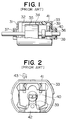
- Figure 1 is a longitudinal partly sectional view of a conventional miniature motor;
- Figure 2 is an end view of the end cover of the motor in Figure 1 showing the connectors used to supply power to the commutator brushes;
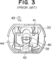
- Figure 3 is an end view of an end cover showing connector arrangement incorporating a resistor;
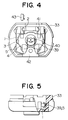
- Figure 4 is an end view of an end cover according to one embodiment of the invention;
- Figure 5 is a partly section view of the end cover of Figure 4;
- Figure 6 is an enlarged end view of an end cover showing an internal terminal prior to its installation within the end cover;
- Figure 7 is a cross-section view of the end cover along line A-A of Figure 6;
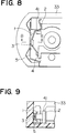
- Figure 8 is an enlarged end view similar to Figure 6, but illustrating the internal terminal installed within the end cover;
- Figure 9 is a cross-sectional view of the end cover on line B-B of Figure 8;
- Figure 10 is an end view similar to Figure 4 showing another embodiment of the invention, incorporating a resistor; and
- Figure 11 is a partly section view of the end cover of Figure 10.
- The motor shown in Figure 1 has a
tubular case 31 closed at one end and made of a metallic material, such as mild steel. Apermanent magnet 32 of tubular segment shape is fixedly fitted to the inner surface thereof.End cover 33 is made of a thermoplastic resin material and engages with an open end of thecase 31.Rotor 34 consists of anarmature 35 facing thepermanent magnet 32 and acommutator 36, and is rotatably supported bybearings case 31 and theend cover 33. -
Brush arm 39 is made of an electrically conductive material, formed into a strip shape, having abrush 40 on one end which makes sliding contact with thecommutator 36. Also inside theend cover 33 is aninternal terminal 41 in contact with thebrush arm 39 so that power may be fed to thearmature 35 from an external dc power source via thebrush arms 39,brushes 40 andcommutator 36. - Thus, as current is fed to the
armature 35, the motor operates in a known manner to drive external equipment (not shown). - Figure 2 is an end view showing the
end cover 33 in Figure 1. Thebrush arm 39 is substantially L-shaped, and fixedly fitted inside theend cover 33 by aholder 42 to force thebrush 40 onto the commutator (not shown) by virtue of its resiliency. Theinternal terminal 41 is made of an electrically conductive strip of material, and fitted inside thecase cover 33 with one end contacting thebrush arm 39, the other end being substantially S-shaped and contacting theexternal power terminal 43 after insertion. - Figure 3 is an end view illustrating an alternative construction of case cover for the motor of Figure 1. In Figure 3, a positive
temperature coefficient resistor 44 is held in position between the substantially U-shapedbrush arm 39 and theinternal terminal 41. The resistance of this device increases sharply if the temperature exceeds a certain level, 100°C for example. Consequently, if the temperature of the miniature motor is increased as a result of the continuous application of an overload or the flow of excessive current when the rotor is jammed, the resistance of the resistor rapidly increases, reducing the current fed to the miniature motor, and thus avoiding overheating and damage. - Conventional motors of the type shown in Figure 3 require a different
internal terminal 41 andbrush arm 39 configuration on one side, in order to accommodate theresistor 44. This increases the number of different components used in each motor and hence leads to an increase in the cost of manufacture. - In the embodiment of the invention shown in Figures 4 and 5, the
brush arm 39 is made of an electrically conductive material, such as copper or copper alloy, and substantially U-shaped, with abrush 40 fixedly fitted to the free end of one leg. The other leg is formed into substantially plate-shaped connectingpart 5 extending along the inside face of theend cover 33, and fitted to thecase cover 33 via aholder 42. - The
internal terminal 41 is made of an electrically conductive material similar to that of thebrush arm 39, and the part extending to the inside of theend cover 33 is formed into a substantially V-shaped connectingpart 1. Anengaging groove 2 is provided in theend cover 33 to receive andexternal power terminal 43. The width of theengaging groove 2 is slightly greater than the width of theinternal terminal 41, and its depth is approximately equal to the thickness of theinternal terminal 41. The movement of theinternal terminal 41 is therefore restricted, particularly when inserting or extracting theexternal power terminal 43. as a result, the displacement of theinternal terminal 41, as found in the prior art referred to above, may be prevented. -
Projections 3, two are shown, are provided on the side of the connectingpart 1 which comes into contact with thebrush arm 39. In the aforementioned construction, the connectingpart 1 of theinternal terminal 41 is fitted between theengaging groove 2, anengaging part 4 provided on theend cover 33 and a connectingpart 5 of thebrush arm 39, in an elastically deformed state. As a result, the connectingpart 1 pushes against the connectingpart 5 of thebrush arm 39 to maintain an electrical connection between theinternal terminal 41 and thebrush arm 39. Theprojection 3 on the connectingpart 1 further improves the reliability of this contact. - As shown in Figures 6 and 7, in order to fit the
internal terminal 41 into position in theend cover 33, the V-shaped connectingpart 1 is elastically deformed by applying a force in the direction indicated by arrow P, and then theinternal terminal 41 may be inserted in thecase cover 33 by applying a force in the direction indicated by arrow Q. The action of the force labelled P causes one end of the connectingpart 1 to slide down theengaging part 4 whilst force Q moves the terminal end past theedge 2a of theengaging groove 2. The extend of the elastic deformation of the connectingpart 1 may be determined appropriately, taking into consideration the pressure to be maintained between the connectingparts - Figures 10 and 11 show an end cover according to another embodiment of this invention. A plate-shaped positive
temperature coefficient resistor 44 is interposed between the connectingpart 1 of theinternal terminal 41 and the connectingpart 5 of thebrush arm 39. -
Projections 6 are provided on the side of the connectingpart 5 of thebrush arm 39 where contact is made with the positivetemperature coefficient resistor 44 in order to form a more reliable connection. It may be necessary to slightly alter the shape and size of the connectingpart 1, relative to that of the equivalent component shown in Figures 4 and 5, to accomodate theresistor 44. This may easily be achieved, simply by changing part of the mold used to form the connectingpart 1 as it is substantially the same in each case. - The present invention offers the following particular benefits:
- (1) The elastic deformation of the connecting part whilst fitted within the end cover improves the reliability of the electrical connection between the internal terminal and the brush arm.
- (2) The internal terminal may be fitted more easily and reliably by locating it in the engaging groove provided on the end cover, leading to improved productivity.
- (3) The miniature motor may be manufactured, with or without a positive temperature coefficient resistor incorporated, using essentially the same set of components, thus reducing the cost of manufacture.
Claims (5)
- A miniature motor having a tubular case (31) closed at one end with a permanent magnet (32) fitted to the inner surface thereof; an end cover (33) closing the open end of the case (31); a rotor (34) comprising an armature (35) and a commutator (36); and brushes (40) supported on the end cover (33) for making sliding contact with the commutator (36), the brushes being mounted on brush arms (39) for connection to external power terminals (43) via internal terminals (41)
CHARACTERISED IN THAT
each brush arm (39) is substantially U-shaped with a respective brush (40) mounted at the end of one limb thereof, the other limb (5) being disposed in the end cover (33) proximate a respective internal terminal (1), each internal terminal being elastically deformed such that it is biased towards said other limb (5) of a brush arm (39), and being located in the end cover (33) by an engaging groove (2) such that its movement perpendicular to a plane defined by the end cover is restricted. - A miniature motor according to Claim 1 wherein a positive temperature coefficient resistor (44) is disposed between an internal terminal (1) and a respective brush arm (39) for controlling the electric current fed to the armature.
- A miniature motor according to Claim 1 or Claim 2 wherein the internal terminal (1) comprises a substantially V-shaped connecting part biased towards the other limb (5) of the respective brush arm (39).
- A miniature motor according to any preceding Claim wherein each internal terminal (1) has a projection (3) directed toward the other limb (5) of the respective brush arm (39).
- A miniature motor according to any preceding claim wherein each brush arm (39) has a projection (6) directed towards the respective internal terminal (1).
Applications Claiming Priority (2)
| Application Number | Priority Date | Filing Date | Title |
|---|---|---|---|
| JP87056/92 | 1992-12-18 | ||
| JP1992087056U JP2562736Y2 (en) | 1992-12-18 | 1992-12-18 | Small motor |
Publications (1)
| Publication Number | Publication Date |
|---|---|
| EP0603000A1 true EP0603000A1 (en) | 1994-06-22 |
Family
ID=13904290
Family Applications (1)
| Application Number | Title | Priority Date | Filing Date |
|---|---|---|---|
| EP93310238A Withdrawn EP0603000A1 (en) | 1992-12-18 | 1993-12-17 | Miniature motor |
Country Status (4)
| Country | Link |
|---|---|
| US (1) | US5434460A (en) |
| EP (1) | EP0603000A1 (en) |
| JP (1) | JP2562736Y2 (en) |
| CN (1) | CN1034899C (en) |
Cited By (1)
| Publication number | Priority date | Publication date | Assignee | Title |
|---|---|---|---|---|
| WO2019097149A1 (en) * | 2017-11-17 | 2019-05-23 | Valeo Systemes Thermiques | Electric motor, particularly for an air blower for a heating, ventilation and/or air conditioning device for a motor vehicle |
Families Citing this family (11)
| Publication number | Priority date | Publication date | Assignee | Title |
|---|---|---|---|---|
| JP2562735Y2 (en) * | 1992-12-17 | 1998-02-16 | マブチモーター株式会社 | Small motor |
| JP3421421B2 (en) * | 1993-06-15 | 2003-06-30 | マブチモーター株式会社 | Small motor |
| JP2686038B2 (en) * | 1993-09-29 | 1997-12-08 | マブチモーター株式会社 | Small motor |
| US6552464B1 (en) | 1999-11-09 | 2003-04-22 | Siemens Canada Limited | Totally integrated engine cooling module for DC motors |
| US6528922B2 (en) | 2000-10-06 | 2003-03-04 | New Bright Industrial Co., Ltd. | Motor housing having simplified cover plate and brush base |
| JP3706301B2 (en) * | 2000-10-31 | 2005-10-12 | マブチモーター株式会社 | Small motor |
| US7345389B2 (en) * | 2004-05-24 | 2008-03-18 | Alps Electric Co., Ltd. | Motor, motor having encoder, and multi-direction input device |
| CN100349366C (en) * | 2005-01-21 | 2007-11-14 | 横店集团东磁有限公司 | Low-interference electric motor |
| JP5362284B2 (en) * | 2008-08-05 | 2013-12-11 | ミネベア株式会社 | Small motor |
| DE102013201715A1 (en) * | 2012-08-28 | 2014-03-06 | Robert Bosch Gmbh | Electric machine for motorized adjustment of moving parts in the motor vehicle, and method for producing the electric machine |
| GB2572350B (en) * | 2018-03-27 | 2023-01-25 | Hitachi Rail Ltd | An electromechanical generator for converting mechanical vibrational energy into electrical energy |
Citations (5)
| Publication number | Priority date | Publication date | Assignee | Title |
|---|---|---|---|---|
| GB2222730A (en) * | 1988-09-09 | 1990-03-14 | Mabuchi Motor Co | Thermistor connected between electric motor brush arm and brush terminal |
| GB2226709A (en) * | 1988-12-30 | 1990-07-04 | Johnson Electric Ind Mfg | Terminal arrangement for an electric motor |
| DE9104028U1 (en) * | 1990-06-05 | 1991-10-17 | Johnson Electric S.A., La Chaux-De-Fonds, Neuenburg, Ch | |
| EP0511776A2 (en) * | 1991-04-29 | 1992-11-04 | Johnson Electric S.A. | A thermally protected electric motor |
| EP0544404A2 (en) * | 1991-10-25 | 1993-06-02 | Mabuchi Motor Kabushiki Kaisha | A miniature motor with an installed earth terminal |
Family Cites Families (2)
| Publication number | Priority date | Publication date | Assignee | Title |
|---|---|---|---|---|
| GB1594334A (en) * | 1976-12-10 | 1981-07-30 | Otter Controls Ltd | Thermal protection for electric motors |
| JP2893135B2 (en) * | 1990-10-19 | 1999-05-17 | ジェイエスアール株式会社 | Liquid curable resin composition for optical fiber coating |
-
1992
- 1992-12-18 JP JP1992087056U patent/JP2562736Y2/en not_active Expired - Lifetime
-
1993
- 1993-12-15 US US08/167,771 patent/US5434460A/en not_active Expired - Lifetime
- 1993-12-17 EP EP93310238A patent/EP0603000A1/en not_active Withdrawn
- 1993-12-18 CN CN93120977A patent/CN1034899C/en not_active Expired - Lifetime
Patent Citations (5)
| Publication number | Priority date | Publication date | Assignee | Title |
|---|---|---|---|---|
| GB2222730A (en) * | 1988-09-09 | 1990-03-14 | Mabuchi Motor Co | Thermistor connected between electric motor brush arm and brush terminal |
| GB2226709A (en) * | 1988-12-30 | 1990-07-04 | Johnson Electric Ind Mfg | Terminal arrangement for an electric motor |
| DE9104028U1 (en) * | 1990-06-05 | 1991-10-17 | Johnson Electric S.A., La Chaux-De-Fonds, Neuenburg, Ch | |
| EP0511776A2 (en) * | 1991-04-29 | 1992-11-04 | Johnson Electric S.A. | A thermally protected electric motor |
| EP0544404A2 (en) * | 1991-10-25 | 1993-06-02 | Mabuchi Motor Kabushiki Kaisha | A miniature motor with an installed earth terminal |
Cited By (2)
| Publication number | Priority date | Publication date | Assignee | Title |
|---|---|---|---|---|
| WO2019097149A1 (en) * | 2017-11-17 | 2019-05-23 | Valeo Systemes Thermiques | Electric motor, particularly for an air blower for a heating, ventilation and/or air conditioning device for a motor vehicle |
| FR3073991A1 (en) * | 2017-11-17 | 2019-05-24 | Valeo Systemes Thermiques | ELECTRIC MOTOR, IN PARTICULAR FOR AN AIR PULSE FOR A HEATING, VENTILATION AND / OR AIR CONDITIONING DEVICE FOR A MOTOR VEHICLE |
Also Published As
| Publication number | Publication date |
|---|---|
| CN1034899C (en) | 1997-05-14 |
| JPH0652370U (en) | 1994-07-15 |
| US5434460A (en) | 1995-07-18 |
| JP2562736Y2 (en) | 1998-02-16 |
| CN1089065A (en) | 1994-07-06 |
Similar Documents
| Publication | Publication Date | Title |
|---|---|---|
| EP0638982B1 (en) | Miniature motor | |
| US5287028A (en) | Miniature motor | |
| EP2187418B1 (en) | Electromagnetic relay | |
| EP0603000A1 (en) | Miniature motor | |
| US4574215A (en) | Brushgear for miniature motors | |
| EP0945937A2 (en) | Electrical terminal | |
| US3967148A (en) | Brush holder assembly | |
| US5648695A (en) | Brush apparatus for electric rotating machine | |
| EP0544404B1 (en) | A miniature motor with an installed earth terminal | |
| US4792307A (en) | Electrical contact and terminal assembly | |
| US4088912A (en) | Brush device for miniature electric motor | |
| EP0284373A2 (en) | Terminal in an electric motor | |
| EP0645872A1 (en) | Miniature motor | |
| JP2708694B2 (en) | Small motor | |
| EP0607032B1 (en) | Miniature motor | |
| JPH07194063A (en) | Small motor and method of connecting with electronic part having built-in motor | |
| US5409407A (en) | Electric connector terminal pieces, electric connectors and electric connectors assembling method | |
| KR0122784Y1 (en) | A small sized electric motor equipped with an electric connector | |
| JPH083178Y2 (en) | Small motor | |
| EP0813757A1 (en) | Electrical motor assembly and contact for use therewith | |
| US5218254A (en) | Miniature motors end cap brush and terminal assembly | |
| US4368938A (en) | Small electric motor | |
| US4414530A (en) | Miniature motor protector apparatus and method for assembling thereof | |
| US5848918A (en) | Electrical appliance with novel electrical power connector structure | |
| JPH06165443A (en) | Motor |
Legal Events
| Date | Code | Title | Description |
|---|---|---|---|
| PUAI | Public reference made under article 153(3) epc to a published international application that has entered the european phase |
Free format text: ORIGINAL CODE: 0009012 |
|
| AK | Designated contracting states |
Kind code of ref document: A1 Designated state(s): DE FR GB IT |
|
| 17P | Request for examination filed |
Effective date: 19941221 |
|
| 17Q | First examination report despatched |
Effective date: 19951002 |
|
| GRAG | Despatch of communication of intention to grant |
Free format text: ORIGINAL CODE: EPIDOS AGRA |
|
| STAA | Information on the status of an ep patent application or granted ep patent |
Free format text: STATUS: THE APPLICATION HAS BEEN WITHDRAWN |
|
| 18W | Application withdrawn |
Withdrawal date: 19961025 |