EP0602971B1 - Pneumatic radial tyre - Google Patents
Pneumatic radial tyre Download PDFInfo
- Publication number
- EP0602971B1 EP0602971B1 EP93310162A EP93310162A EP0602971B1 EP 0602971 B1 EP0602971 B1 EP 0602971B1 EP 93310162 A EP93310162 A EP 93310162A EP 93310162 A EP93310162 A EP 93310162A EP 0602971 B1 EP0602971 B1 EP 0602971B1
- Authority
- EP
- European Patent Office
- Prior art keywords
- groove
- straight
- grooves
- sub
- depth
- Prior art date
- Legal status (The legal status is an assumption and is not a legal conclusion. Google has not performed a legal analysis and makes no representation as to the accuracy of the status listed.)
- Expired - Lifetime
Links
- XLYOFNOQVPJJNP-UHFFFAOYSA-N water Substances O XLYOFNOQVPJJNP-UHFFFAOYSA-N 0.000 description 10
- 230000001154 acute effect Effects 0.000 description 5
- 230000000052 comparative effect Effects 0.000 description 5
- 230000001965 increasing effect Effects 0.000 description 5
- 238000013459 approach Methods 0.000 description 2
- 238000010276 construction Methods 0.000 description 1
- 238000010586 diagram Methods 0.000 description 1
- 230000002708 enhancing effect Effects 0.000 description 1
- 238000009434 installation Methods 0.000 description 1
- 230000003014 reinforcing effect Effects 0.000 description 1
- 238000005096 rolling process Methods 0.000 description 1
- 239000000758 substrate Substances 0.000 description 1
Images

Classifications
-
- B—PERFORMING OPERATIONS; TRANSPORTING
- B60—VEHICLES IN GENERAL
- B60C—VEHICLE TYRES; TYRE INFLATION; TYRE CHANGING; CONNECTING VALVES TO INFLATABLE ELASTIC BODIES IN GENERAL; DEVICES OR ARRANGEMENTS RELATED TO TYRES
- B60C11/00—Tyre tread bands; Tread patterns; Anti-skid inserts
- B60C11/03—Tread patterns
- B60C11/13—Tread patterns characterised by the groove cross-section, e.g. for buttressing or preventing stone-trapping
- B60C11/1369—Tie bars for linking block elements and bridging the groove
-
- B—PERFORMING OPERATIONS; TRANSPORTING
- B60—VEHICLES IN GENERAL
- B60C—VEHICLE TYRES; TYRE INFLATION; TYRE CHANGING; CONNECTING VALVES TO INFLATABLE ELASTIC BODIES IN GENERAL; DEVICES OR ARRANGEMENTS RELATED TO TYRES
- B60C11/00—Tyre tread bands; Tread patterns; Anti-skid inserts
- B60C11/03—Tread patterns
- B60C11/0306—Patterns comprising block rows or discontinuous ribs
- B60C11/0309—Patterns comprising block rows or discontinuous ribs further characterised by the groove cross-section
-
- B—PERFORMING OPERATIONS; TRANSPORTING
- B60—VEHICLES IN GENERAL
- B60C—VEHICLE TYRES; TYRE INFLATION; TYRE CHANGING; CONNECTING VALVES TO INFLATABLE ELASTIC BODIES IN GENERAL; DEVICES OR ARRANGEMENTS RELATED TO TYRES
- B60C11/00—Tyre tread bands; Tread patterns; Anti-skid inserts
- B60C11/03—Tread patterns
- B60C2011/0337—Tread patterns characterised by particular design features of the pattern
- B60C2011/0339—Grooves
- B60C2011/0341—Circumferential grooves
- B60C2011/0348—Narrow grooves, i.e. having a width of less than 4 mm
-
- B—PERFORMING OPERATIONS; TRANSPORTING
- B60—VEHICLES IN GENERAL
- B60C—VEHICLE TYRES; TYRE INFLATION; TYRE CHANGING; CONNECTING VALVES TO INFLATABLE ELASTIC BODIES IN GENERAL; DEVICES OR ARRANGEMENTS RELATED TO TYRES
- B60C11/00—Tyre tread bands; Tread patterns; Anti-skid inserts
- B60C11/03—Tread patterns
- B60C2011/0337—Tread patterns characterised by particular design features of the pattern
- B60C2011/0339—Grooves
- B60C2011/0341—Circumferential grooves
- B60C2011/0355—Circumferential grooves characterised by depth
-
- Y—GENERAL TAGGING OF NEW TECHNOLOGICAL DEVELOPMENTS; GENERAL TAGGING OF CROSS-SECTIONAL TECHNOLOGIES SPANNING OVER SEVERAL SECTIONS OF THE IPC; TECHNICAL SUBJECTS COVERED BY FORMER USPC CROSS-REFERENCE ART COLLECTIONS [XRACs] AND DIGESTS
- Y10—TECHNICAL SUBJECTS COVERED BY FORMER USPC
- Y10S—TECHNICAL SUBJECTS COVERED BY FORMER USPC CROSS-REFERENCE ART COLLECTIONS [XRACs] AND DIGESTS
- Y10S152/00—Resilient tires and wheels
- Y10S152/903—Non-directional tread pattern having non-circumferential transverse groove following smooth curved path
Definitions
- the present invention relates to a pneumatic radial tyre provided with a tread pattern having straight grooves that extend circumferentially around the tread.
- Recent passenger car tyres are in many cases provided with a rib pattern, or a tread pattern that has straight grooves extending circumferentially around the tread, because it offers the following advantages: small rolling resistance, good ride characteristics, good steering stability, low noise between the tyre and the road surface, and less likelihood of "hydroplaning" in the presence of a water film on the road surface.
- An object, therefore, of the present invention is to provide a pneumatic radial tyre that has straight grooves of broad and narrow width and which is adapted to ensure sufficient rigidity in the tread to provide better steering stability.
- a pneumatic radial tyre has at least one, circumferentially extending wide straight groove (2), a straight circumferentially extending sub-groove (3) narrower than the middle groove and a plurality of transverse lug grooves (5) which extend transversely across the tread, characterised by the grooves combining to form acute-angled blocks each having a land angle which is greater than zero degrees but less than 70 degrees (0° ⁇ 70°), and tie bars (10) with a circumferential length of L 1 and a depth of D 1 provided within the sub-groove (3) between adjacent blocks in the transverse direction of the tread, said tie bars (10) satisfying the following relationships: L 1 ⁇ 0.7 ⁇ A 0.1 ⁇ D ⁇ D 1 ⁇ 0.5 D D-1.6mm ⁇ D 2 ⁇ (D-1.6mm)x0.5 D 1 ⁇ D 2 where
- the resultant tread has a ratio S C /S L where S C is the total area of openings in the groove regions and S L is the total area of the land regions, i.e. those block surfaces in the tread which come in contact with the road surface) which is increased sufficiently to permit effective water drainage, and the grooves serve as sipes to provide better wet performance in the presence of a water film on the road surface and offer better ride characteristics.
- the narrow sub-grooves combine with the lug grooves to form acute-angled blocks that each have a land angle ⁇ which is greater than zero degrees but less than 70 degrees (0° ⁇ 70°) with respect to the sub-grooves and this design contributes even better ride characteristics.
- tie bars having a circumferential length of L 1 and a depth of D 1 are provided within the narrow width sub-groove between adjacent blocks in the transverse direction of the tread.
- the tie bars which satisfy the four conditions set forth above reinforce the acute-angled portions of the blocks to make them more rigid, thereby improving the steering stability characteristics of the tyre.
- the tread of the tyre is provided in the central portion with two spaced apart broad width straight centre grooves 1 which extend circumferentially around the tread.
- Two straight middle grooves 2 extend circumferentially around the tread positioned transversely outwards of and a distance from each of the centre grooves 1.
- a straight sub-groove 3 On each side of the tyre, between the centre groove 1 and the adjacent straight groove 2, there is provided a straight sub-groove 3 that is narrower than the straight groove 1 and which extends circumferentially around the tread.
- a shoulder straight sub-groove 4 which is also narrower than the straight groove 2 and which extends circumferentially is provided transversely outwards of the straight groove 2 by a given distance.
- the sub-groove 3 and the shoulder straight sub-groove 4 have a width of 0.5 to 3.0mm and their depth is 80% to 15% of the depth of the grooves that are provided with wear indicators (which are usually the centre groove 1 and the straight groove 2). If the width of the sub-groove 3 and the shoulder sub-groove 4 is less than 0.5mm, there is too little water drainage.
- grooves 1 to 4 need not be strictly straight and may be in a zigzag form.
- the ratio of S C (the total area of the openings in the groove regions) to S L (the total area of land portions i.e. those block surfaces in the tread which come in contact with the road surface) is set sufficiently large to permit effective water drainage and the grooves serve as sipes to provide better wet performance in the presence of a water film on the road surface and offer better ride characteristics.
- a plurality of lug grooves 5 each of which intersect the grooves 1 to 4 at predetermined angles extend from the centre groove 1 to the edge of the tread in a transverse direction in such a way that the lug grooves 5 are provided on either side of the two centre grooves 1 taken as a whole or pair.
- the lug grooves 5 on the opposite sides of the pair of centre grooves 1 are arranged to have point symmetry with respect to a point on the centreline of the tread.
- a row of centre blocks 6 is formed between the two centre grooves, a row of middle blocks 7 is formed between each centre groove 1 and one of the straight grooves 2, and a row of shoulder blocks 8 is formed axially outwards of each middle groove 2.
- the centre blocks 6 each have comparable angles to the lug grooves 5 with respect to the circumferential direction and a plurality of centre blocks 61 are formed in segments divided up by sipes 9 that are aligned with the lug grooves 5 on either side of the unit of centre grooves 1.
- a row of middle blocks 7 is provided on both sides of the single row of centre blocks 6.
- Each row of middle blocks consists of inner middle blocks and outer middle blocks that are defined by sub-grooves 3 and the lug grooves 5. As shown, the inner middle blocks are designated by 71 and 73, and the outer middle blocks are designated by 72 and 74.
- the row of shoulder blocks 8 is provided on both outer sides of the single row of centre blocks 6.
- Each row of shoulder blocks consists of inner shoulder blocks 81 and outer shoulder blocks 82 defined by shoulder sub-grooves 4 and the lug grooves 5.
- Each of the inner middle blocks 71 in the row of middle blocks 7 shown on the right side in Figure 1 comprises a step-in side 711 which faces the lug groove 5 in the step-in portion, an axially outer lateral side 712 which faces the sub-groove 3, an axially inner lateral side 713 which faces the centre groove 1, a kickout side 714 which faces the lug groove 5 in the kickout portion, an oblique side 715 which faces both the centre groove 1 and the lug groove 5 in the kickout portion.
- Each of the outer middle blocks 71 comprises a step-in side 721 which faces the lug groove 5 in the step-in portion, an axially inner lateral side 722 which faces the sub-groove 3, and axially outer lateral side 723 which face the straight groove 2, and a kickout side 724 which faces the lug groove 5 in the kickout portion.
- the acute angle formed by the substrate groove 3 and the lug groove 5 in each inner middle block 71 may be defined as a land angle ⁇ 1 . More particularly, the acute land angle formed by the step-in side 711 and the outer lateral side 712 is defined as the land angle ⁇ 1 for the inner middle block 71. On the other hand, the acute vertical angle formed by the inner lateral side 722 and the kickout side 724 in each outer middle blocks 72 is defined as land angle ⁇ 2 . In accordance with the present invention, each of the land angles ⁇ 1 and ⁇ 2 is greater than zero degrees but less than 70 degrees (0° ⁇ 1 ⁇ 70°;0° ⁇ 2 ⁇ 70°). Thus in general 0° ⁇ 70°.
- the sub-groove 3 which is located between the row of inner middle blocks 71 and the row of outer middle blocks 72 is furnished with tie bars (10, 11) that reinforce the acute-angled portions of each of the inner middle blocks 71 and outer middle blocks 72.
- Each tie bar consists of an inner tie bar 10 and an outer tie bar 11.
- the inner tire bar 10 having a length of L 1 contacts the land angle ⁇ 1 of each inner middle block 71 (namely, it contacts the outer lateral side 712) and extends from the site where the sidewall of the lug groove 5 faced by the step-in side 711 intersects with the sub-groove 3.
- the outer tie bar 11, having a length of L 2 contacts the land angle ⁇ 2 of each outer middle block 72 (namely, it contacts the inner lateral side 722) and extends from the site where the sidewall of the lug groove 5 faced by the kickout side 724 intersects with the sub-groove 3.
- D 1 for the depth of each of the inner tie bar 10 and outer tie bar 11 respectively as measured from the surface of the tread
- D 2 for the depth of the sub-groove 3 between the inner tie bar 10 and the outer tie bar 11
- D for the depth of the grooves which are provided with wear indicators (which are usually the centre grooves 1 and the straight grooves 2)
- s i for the length of the step-in side 711 of each inner middle block 71
- A for the length of the step-in side 711 as taken along the sub-groove 3
- s o for the length of the kickout side 724 of each outer middle block 72
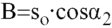
- B for the length of the kickout side 724 as taken along the sub-groove 3.
- the inner middle blocks 73 and the other middle blocks 74 in the row of middle blocks 7 which are located on the left side of Figure 1 are formed to have point symmetry with the inner middle blocks 71 and the outer middle blocks 72 in the right row of middle blocks 7 with respect to a point on the centreline through the tread.
- the relationship between the step-in and kickout portions in the left row of middle blocks is opposite to that in the right row of middle blocks.
- the land angle ⁇ 3 which is the acute angle located in the kickout portion of the inner middle block 73 corresponds to the land angle ⁇ 1 of the inner middle block 71
- the land angle ⁇ 4 of the outer middle block 74 corresponds to the land angle ⁇ 2 of the outer middle block 72.
- the tyre of the invention was very satisfactory in terms of steering stability, wet performance and appearance compared to the comparison tyres which were poor.
- the present invention offers the following advantages. since the tread having straight grooves of broad width is also provided with straight grooves of narrow width, the ratio S C (the total area of openings in the groove regions) to S L (the total area of the land regions, i.e. those block surfaces in the tread which come in contact with the road surface) is increased sufficiently to permit more effective water drainage, and the grooves serve as sipes to provide better wet performance in the presence of a water film on the road surface and offer better ride characteristics.
- the straight grooves of narrow width combine with the lug grooves to form acute-angled blocks that each have a land angle ⁇ which is greater than zero degrees but less than 70 degrees (0° ⁇ 70°) with respect to the straight grooves and this design contributes to even better ride characteristics.
- tie bars having a circumferential length of L 1 and a depth of D 1 are provided within the straight groove of narrow width between blocks that are adjacent to each other in the transverse direction of the tread.
- the tie bars which satisfy the four conditions set forth hereinabove reinforce the acute-angled portions of the blocks to make them more rigid, thereby improving the steering stability characteristics of the tyre.
Landscapes
- Engineering & Computer Science (AREA)
- Mechanical Engineering (AREA)
- Tires In General (AREA)
Description
- The present invention relates to a pneumatic radial tyre provided with a tread pattern having straight grooves that extend circumferentially around the tread.
- Recent passenger car tyres are in many cases provided with a rib pattern, or a tread pattern that has straight grooves extending circumferentially around the tread, because it offers the following advantages: small rolling resistance, good ride characteristics, good steering stability, low noise between the tyre and the road surface, and less likelihood of "hydroplaning" in the presence of a water film on the road surface.
- In order to further reduce the noise that develops between the tyre and the road surface and to suppress more effectively the occurrence of "hydroplaning" in the presence of a water film on the road surface while enhancing the drive and brake forces, various approaches are being adopted. These approaches include increasing not only the number of straight grooves, but also the number of transverse or lug grooves that intersect with the straight grooves and extend transversely across the tread, as well as increasing the angle the lug grooves form with respect to the straight grooves.
- However, if the number of straight grooves and lug grooves are simply increased in a conventional pneumatic radial tyre, the area of each of the blocks formed by the straight grooves and lug grooves will decrease, leading to lower rigidity of the blocks and poor steering ability.
- An object, therefore, of the present invention is to provide a pneumatic radial tyre that has straight grooves of broad and narrow width and which is adapted to ensure sufficient rigidity in the tread to provide better steering stability.
- According to one aspect of the present invention a pneumatic radial tyre has at least one, circumferentially extending wide straight groove (2), a straight circumferentially extending sub-groove (3) narrower than the middle groove and a plurality of transverse lug grooves (5) which extend transversely across the tread, characterised by the grooves combining to form acute-angled blocks each having a land angle which is greater than zero degrees but less than 70 degrees (0°<α<70°), and tie bars (10) with a circumferential length of L1 and a depth of D1 provided within the sub-groove (3) between adjacent blocks in the transverse direction of the tread, said tie bars (10) satisfying the following relationships:

- D2:
- the depth of the sub-groove (3) in which said tie bars (10) are provided;
- D:
- the depth of a groove provided with a wear indicator:
- A:
- the length of the side of each block that faces the lug groove and which forms the land angle as taken along either of the two straight grooves.
- The resultant tread has a ratio SC/SL where SC is the total area of openings in the groove regions and SL is the total area of the land regions, i.e. those block surfaces in the tread which come in contact with the road surface) which is increased sufficiently to permit effective water drainage, and the grooves serve as sipes to provide better wet performance in the presence of a water film on the road surface and offer better ride characteristics.
- In accordance with the present invention, the narrow sub-grooves combine with the lug grooves to form acute-angled blocks that each have a land angle α which is greater than zero degrees but less than 70 degrees (0°<α<70°) with respect to the sub-grooves and this design contributes even better ride characteristics.
- Furthermore, tie bars having a circumferential length of L1 and a depth of D1 are provided within the narrow width sub-groove between adjacent blocks in the transverse direction of the tread. The tie bars which satisfy the four conditions set forth above reinforce the acute-angled portions of the blocks to make them more rigid, thereby improving the steering stability characteristics of the tyre.
- An embodiment of the present invention is described below with reference to the accompanying diagrammatic drawings in which:
- Figure 1 shows a tread pattern of a tyre; and
- Figure 2 is a diagram showing a section of Figure 1 taken on line II-II.
- As shown in Figure 1, the tread of the tyre is provided in the central portion with two spaced apart broad width straight centre grooves 1 which extend circumferentially around the tread. Two
straight middle grooves 2 extend circumferentially around the tread positioned transversely outwards of and a distance from each of the centre grooves 1. - On each side of the tyre, between the centre groove 1 and the adjacent
straight groove 2, there is provided astraight sub-groove 3 that is narrower than the straight groove 1 and which extends circumferentially around the tread. A shoulderstraight sub-groove 4 which is also narrower than thestraight groove 2 and which extends circumferentially is provided transversely outwards of thestraight groove 2 by a given distance. - To take a typical example, the
sub-groove 3 and the shoulderstraight sub-groove 4 have a width of 0.5 to 3.0mm and their depth is 80% to 15% of the depth of the grooves that are provided with wear indicators (which are usually the centre groove 1 and the straight groove 2). If the width of thesub-groove 3 and theshoulder sub-groove 4 is less than 0.5mm, there is too little water drainage. - It should be noted that the grooves 1 to 4 need not be strictly straight and may be in a zigzag form.
- With the arrangement just described above, the ratio of SC (the total area of the openings in the groove regions) to SL (the total area of land portions i.e. those block surfaces in the tread which come in contact with the road surface) is set sufficiently large to permit effective water drainage and the grooves serve as sipes to provide better wet performance in the presence of a water film on the road surface and offer better ride characteristics.
- A plurality of
lug grooves 5 each of which intersect the grooves 1 to 4 at predetermined angles extend from the centre groove 1 to the edge of the tread in a transverse direction in such a way that thelug grooves 5 are provided on either side of the two centre grooves 1 taken as a whole or pair. Thelug grooves 5 on the opposite sides of the pair of centre grooves 1 are arranged to have point symmetry with respect to a point on the centreline of the tread. - A row of
centre blocks 6 is formed between the two centre grooves, a row of middle blocks 7 is formed between each centre groove 1 and one of thestraight grooves 2, and a row ofshoulder blocks 8 is formed axially outwards of eachmiddle groove 2. - The
centre blocks 6 each have comparable angles to thelug grooves 5 with respect to the circumferential direction and a plurality ofcentre blocks 61 are formed in segments divided up by sipes 9 that are aligned with thelug grooves 5 on either side of the unit of centre grooves 1. - A row of middle blocks 7 is provided on both sides of the single row of
centre blocks 6. Each row of middle blocks consists of inner middle blocks and outer middle blocks that are defined bysub-grooves 3 and thelug grooves 5. As shown, the inner middle blocks are designated by 71 and 73, and the outer middle blocks are designated by 72 and 74. - The row of
shoulder blocks 8 is provided on both outer sides of the single row ofcentre blocks 6. - Each row of shoulder blocks consists of inner shoulder blocks 81 and outer shoulder blocks 82 defined by
shoulder sub-grooves 4 and thelug grooves 5. - Each of the
inner middle blocks 71 in the row of middle blocks 7 shown on the right side in Figure 1 comprises a step-inside 711 which faces thelug groove 5 in the step-in portion, an axially outerlateral side 712 which faces thesub-groove 3, an axially innerlateral side 713 which faces the centre groove 1, akickout side 714 which faces thelug groove 5 in the kickout portion, anoblique side 715 which faces both the centre groove 1 and thelug groove 5 in the kickout portion. Each of theouter middle blocks 71 comprises a step-inside 721 which faces thelug groove 5 in the step-in portion, an axially innerlateral side 722 which faces thesub-groove 3, and axially outerlateral side 723 which face thestraight groove 2, and akickout side 724 which faces thelug groove 5 in the kickout portion. - The acute angle formed by the
substrate groove 3 and thelug groove 5 in eachinner middle block 71 may be defined as a land angle α1. More particularly, the acute land angle formed by the step-inside 711 and the outerlateral side 712 is defined as the land angle α1 for theinner middle block 71. On the other hand, the acute vertical angle formed by the innerlateral side 722 and thekickout side 724 in eachouter middle blocks 72 is defined as land angle α2. In accordance with the present invention, each of the land angles α1 and α2 is greater than zero degrees but less than 70 degrees (0°<α1<70°;0°<α2<70°). Thus in general 0°<α<70°. - As Figure 2 shows, the
sub-groove 3 which is located between the row ofinner middle blocks 71 and the row ofouter middle blocks 72 is furnished with tie bars (10, 11) that reinforce the acute-angled portions of each of theinner middle blocks 71 andouter middle blocks 72. - Each tie bar consists of an
inner tie bar 10 and anouter tie bar 11. Theinner tire bar 10 having a length of L1 contacts the land angle α1 of each inner middle block 71 (namely, it contacts the outer lateral side 712) and extends from the site where the sidewall of thelug groove 5 faced by the step-inside 711 intersects with thesub-groove 3. Theouter tie bar 11, having a length of L2, contacts the land angle α2 of each outer middle block 72 (namely, it contacts the inner lateral side 722) and extends from the site where the sidewall of thelug groove 5 faced by thekickout side 724 intersects with thesub-groove 3. Various parameters for the tie bars and associated components are written using the following symbols: D1 for the depth of each of theinner tie bar 10 andouter tie bar 11 respectively as measured from the surface of the tread; D2 for the depth of thesub-groove 3 between theinner tie bar 10 and theouter tie bar 11; D for the depth of the grooves which are provided with wear indicators (which are usually the centre grooves 1 and the straight grooves 2); si for the length of the step-inside 711 of eachinner middle block 71; A for the length of the step-inside 711 as taken along thesub-groove 3; so for the length of thekickout side 724 of eachouter middle block 72; and B for the length of thekickout side 724 as taken along thesub-groove 3. Unless D1 is 50% of D or less, the tie bars will not produce satisfactory reinforcing effects. On the other hand, the greater the value of D2, which refers to the depth of those portions of thesub-groove 3 where no tie bars are provided, the better is the appearance of the tyre in the middle and subsequent phases of wear. Under these circumstances, the following relationships will hold: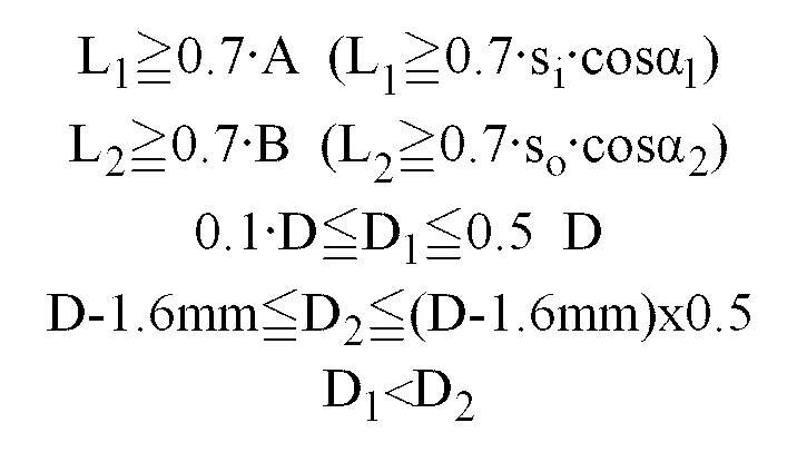

- The
inner middle blocks 73 and theother middle blocks 74 in the row of middle blocks 7 which are located on the left side of Figure 1 are formed to have point symmetry with theinner middle blocks 71 and theouter middle blocks 72 in the right row of middle blocks 7 with respect to a point on the centreline through the tread. Thus, the relationship between the step-in and kickout portions in the left row of middle blocks is opposite to that in the right row of middle blocks. Stated more specifically, the land angle α3 which is the acute angle located in the kickout portion of the innermiddle block 73 corresponds to the land angle α1 of the innermiddle block 71, whereas the land angle α4 of the outermiddle block 74 corresponds to the land angle α2 of the outermiddle block 72. the former two land angles are the same (
- A tyre was constructed and tested in comparison with tyres of the convention structure according to Comparative Examples I to IV. The results of the test are shown in Table 1 below.
- All tyres under test were of size 185/60R14. the tyre of Comparative Example I had tie bars with dimensions outside the ranges specified by the present invention, the tyre of Comparative Example II had not tie bars, the tyre of Comparative Example III was characterised in that all the (fine) straight grooves of narrow width that extended circumferentially were made with a shallow depth, and the tyre of Comparative Example IV had no straight grooves of narrow width extending circumferentially.
- The greater the values for the test data as shown in Table 1, the better.
Table 1 Ex. Comp.Ex.1 Comp.Ex II (without tie bars) Comp Ex III (all fine grooves shallow) Comp Ex IV (without fine grooves) Tie bar installation dimensions 0.75A 0.5A - - - 0.8B 0.9B - - - 3.0mm 3.0mm 5.0mm 3.0mm - 5.0mm 5.0mm 5.0mm 3.0mm - 8.0mm 8.0mm 8.0mm 8.0mm 8.0 mm Steering stability 3 3 2.8 3+ 3.1 Ride 3 3 3+ 2.9 2.8 Hydroplaning 3 3 3 3 3- Wet performance in the presence of water film 3 3 3 3 3- Appearance after test on steering stability 3 2.8 2.6 3+ 3+ - As is clear from Table 1, the tyre of the invention was very satisfactory in terms of steering stability, wet performance and appearance compared to the comparison tyres which were poor.
- Having the construction described hereinabove, the present invention offers the following advantages. since the tread having straight grooves of broad width is also provided with straight grooves of narrow width, the ratio SC (the total area of openings in the groove regions) to SL (the total area of the land regions, i.e. those block surfaces in the tread which come in contact with the road surface) is increased sufficiently to permit more effective water drainage, and the grooves serve as sipes to provide better wet performance in the presence of a water film on the road surface and offer better ride characteristics.
- The straight grooves of narrow width combine with the lug grooves to form acute-angled blocks that each have a land angle α which is greater than zero degrees but less than 70 degrees (0°<α<70°) with respect to the straight grooves and this design contributes to even better ride characteristics.
- Furthermore, tie bars having a circumferential length of L1 and a depth of D1 are provided within the straight groove of narrow width between blocks that are adjacent to each other in the transverse direction of the tread. The tie bars which satisfy the four conditions set forth hereinabove reinforce the acute-angled portions of the blocks to make them more rigid, thereby improving the steering stability characteristics of the tyre.
Claims (5)
- A pneumatic radial tyre having at least one circumferentially extending wide straight groove (2), a straight circumferentially extending sub-groove (3) narrower than the middle groove (1) and a plurality of transverse lug grooves (5) which extend transversely across the tread, characterised by the grooves combining to form acute-angled blocks each having a land angle α which is greater than zero degrees but less than 70 degrees (0°<α<70°), and tie bars (10, 11), wherein the inner tie bar (10) has a circumferential length of L1 and a depth of D1 provided within the sub-groove (3) between adjacent blocks in the transverse direction of the tread, said tie bars (10) satisfying the following relationships:
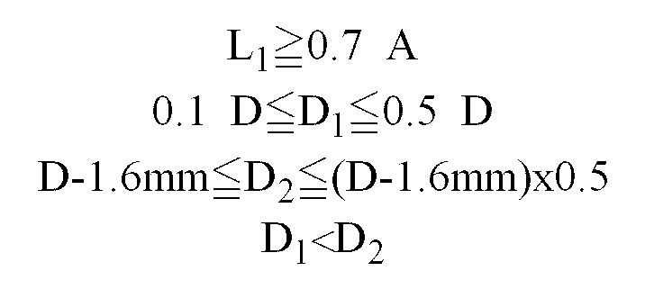 D2: the depth of the sub-groove (3) in which said tie bars (10) are provided;D: the depth of a groove provided with a wear indicator;A: the length of the side of each block that faces the lug groove and which forms the land angle α as taken along either of the two straight grooves.
 - A tyre according to claim 1, characterised by a straight centre groove (1), this groove and the straight groove (2) being wide grooves substantially wider than the sub-groove (3).
- A tyre according to claim 2, characterised by a substantially straight shoulder groove (4) provided in each shoulder region having a width in the range of 0.5 to 3.0mm and a depth of 80 to 15% the depth of either the centre groove (1) or the straight groove (2).
- A tyre according to claim 2 or 3, characterised in that the centre groove (1), straight groove (2) and sub-groove (3) have a zigzag form.
- A tyre according to any one of claims 1 to 4 characterised in that the tie bars comprise an inner tie bar (10) and an outer tie bar (11), the outer tie bar having a length L2 and extending from the site where the sidewall and the lug groove (5) intersect with the sub-groove (3).
Applications Claiming Priority (2)
| Application Number | Priority Date | Filing Date | Title |
|---|---|---|---|
| JP353874/92 | 1992-12-16 | ||
| JP4353874A JP2864439B2 (en) | 1992-12-16 | 1992-12-16 | Pneumatic radial tire |
Publications (2)
| Publication Number | Publication Date |
|---|---|
| EP0602971A1 EP0602971A1 (en) | 1994-06-22 |
| EP0602971B1 true EP0602971B1 (en) | 1996-08-21 |
Family
ID=18433809
Family Applications (1)
| Application Number | Title | Priority Date | Filing Date |
|---|---|---|---|
| EP93310162A Expired - Lifetime EP0602971B1 (en) | 1992-12-16 | 1993-12-16 | Pneumatic radial tyre |
Country Status (4)
| Country | Link |
|---|---|
| US (1) | US5439040A (en) |
| EP (1) | EP0602971B1 (en) |
| JP (1) | JP2864439B2 (en) |
| DE (1) | DE69304181T2 (en) |
Families Citing this family (19)
| Publication number | Priority date | Publication date | Assignee | Title |
|---|---|---|---|---|
| US5603785A (en) * | 1994-05-06 | 1997-02-18 | The Goodyear Tire & Rubber Company | Tire including two aquachannels on one side |
| US5746849A (en) * | 1995-12-11 | 1998-05-05 | The Goodyear Tire & Rubber Company | Tire tread including tie bar |
| USD384919S (en) * | 1996-07-29 | 1997-10-14 | The Goodyear Tire & Rubber Company | Tire tread |
| USD391204S (en) | 1996-12-16 | 1998-02-24 | The Goodyear Tire & Rubber Company | Tire tread |
| JP3363370B2 (en) * | 1998-02-12 | 2003-01-08 | 住友ゴム工業株式会社 | Pneumatic tire |
| USD407679S (en) | 1998-06-16 | 1999-04-06 | The Goodyear Tire & Rubber Company | Tire tread |
| US6631746B2 (en) | 2001-04-25 | 2003-10-14 | Bridgestone/Firestone North American Tire, Llc | Undercut tie bar for pneumatic tire |
| US6695024B2 (en) | 2001-08-03 | 2004-02-24 | Bridgestone/Firestone North American Tire, Llc | Pneumatic tire having tapered tie bars |
| EP1535759B1 (en) * | 2003-11-27 | 2007-01-24 | Continental Aktiengesellschaft | Pneumatic tire |
| JP4530407B2 (en) * | 2004-07-20 | 2010-08-25 | 東洋ゴム工業株式会社 | Pneumatic tire |
| WO2013066309A1 (en) * | 2011-10-31 | 2013-05-10 | Michelin Recherche Et Technique S.A. | Variable height grooves in multiple wear layer treads for retreaded tires |
| JP6012298B2 (en) * | 2012-07-05 | 2016-10-25 | 株式会社ブリヂストン | Pneumatic tire |
| JP6093257B2 (en) * | 2013-07-05 | 2017-03-08 | 住友ゴム工業株式会社 | Pneumatic tire |
| JP6400423B2 (en) * | 2014-10-09 | 2018-10-03 | 東洋ゴム工業株式会社 | Pneumatic tire |
| JP5939296B2 (en) * | 2014-12-01 | 2016-06-22 | 横浜ゴム株式会社 | Pneumatic tire |
| JP5910709B1 (en) * | 2014-12-01 | 2016-04-27 | 横浜ゴム株式会社 | Pneumatic tire |
| JP6903880B2 (en) * | 2016-08-19 | 2021-07-14 | 横浜ゴム株式会社 | Pneumatic tires |
| CN108189624A (en) * | 2018-02-09 | 2018-06-22 | 建大橡胶(中国)有限公司 | A kind of sports type rib tire |
| JP7099498B2 (en) * | 2020-08-05 | 2022-07-12 | 横浜ゴム株式会社 | tire |
Family Cites Families (20)
| Publication number | Priority date | Publication date | Assignee | Title |
|---|---|---|---|---|
| NL89466C (en) * | 1953-10-22 | |||
| GB869980A (en) * | 1958-06-20 | 1961-06-07 | Us Rubber Co | Improvements in slotted tyre tread |
| US3012599A (en) * | 1958-06-20 | 1961-12-12 | Us Rubber Co | Slotted tire tread |
| JPS52111104A (en) * | 1976-03-15 | 1977-09-17 | Bridgestone Corp | Pneumatic tire for heavy vehicle |
| JPS54155503A (en) * | 1978-05-26 | 1979-12-07 | Bridgestone Corp | Heavy-load pneumatic tyre excellent in its water draining performance |
| US4353402A (en) * | 1978-06-16 | 1982-10-12 | Bandag Incorporated | Slitted tire tread |
| JPS5918002A (en) * | 1982-07-21 | 1984-01-30 | Bridgestone Corp | Pneumatic tyre for heavy load |
| DE8628836U1 (en) * | 1986-10-29 | 1988-02-25 | Uniroyal Englebert Reifen GmbH, 5100 Aachen | Pneumatic vehicle tires |
| IT8722144V0 (en) * | 1986-08-05 | 1987-07-31 | Uniroyal Englebert Gmbh | CARVING OF TIRES OF MOTOR VEHICLES. |
| JP2639449B2 (en) * | 1986-11-07 | 1997-08-13 | 株式会社 ブリヂストン | Pneumatic radial tire |
| JP2644499B2 (en) * | 1987-07-31 | 1997-08-25 | 株式会社ブリヂストン | Pneumatic radial tire for high speed |
| JPH01309806A (en) * | 1988-06-07 | 1989-12-14 | Yokohama Rubber Co Ltd:The | Pneumatic tire |
| JPH0241908A (en) * | 1988-08-02 | 1990-02-13 | Bridgestone Corp | Pneumatic tire |
| AT394337B (en) * | 1989-04-13 | 1992-03-10 | Semperit Ag | RADIAL TIRES FOR TRUCKS |
| JPH03182814A (en) * | 1989-12-11 | 1991-08-08 | Sumitomo Rubber Ind Ltd | Snow tire |
| US5088536A (en) * | 1990-05-10 | 1992-02-18 | The Goodyear Tire & Rubber Company | All season type tire tread |
| JP3098247B2 (en) * | 1990-05-31 | 2000-10-16 | 株式会社ブリヂストン | Pneumatic retirement |
| US5238038A (en) * | 1990-09-04 | 1993-08-24 | The Goodyear Tire & Rubber Company | Pneumatic tire |
| DE9016455U1 (en) * | 1990-12-04 | 1991-07-25 | Uniroyal Englebert Reifen GmbH, 5100 Aachen | Pneumatic vehicle tires |
| US5176766B1 (en) * | 1991-03-08 | 1996-04-30 | Goodyear Tire & Rubber | Pneumatic tire having a unique footprint |
-
1992
- 1992-12-16 JP JP4353874A patent/JP2864439B2/en not_active Expired - Fee Related
-
1993
- 1993-12-16 DE DE69304181T patent/DE69304181T2/en not_active Expired - Fee Related
- 1993-12-16 EP EP93310162A patent/EP0602971B1/en not_active Expired - Lifetime
- 1993-12-16 US US08/167,093 patent/US5439040A/en not_active Expired - Fee Related
Also Published As
| Publication number | Publication date |
|---|---|
| DE69304181D1 (en) | 1996-09-26 |
| DE69304181T2 (en) | 1997-01-02 |
| US5439040A (en) | 1995-08-08 |
| JPH06183211A (en) | 1994-07-05 |
| EP0602971A1 (en) | 1994-06-22 |
| JP2864439B2 (en) | 1999-03-03 |
Similar Documents
| Publication | Publication Date | Title |
|---|---|---|
| EP0602971B1 (en) | Pneumatic radial tyre | |
| JP2650040B2 (en) | Pneumatic tires for passenger cars | |
| EP2204294B1 (en) | Pneumatic tire | |
| EP3351407B1 (en) | Tire | |
| EP2308695B1 (en) | Pneumatic tire | |
| EP3135504B1 (en) | Heavy duty tire | |
| EP2199111B1 (en) | Pneumatic tire with sipes | |
| EP2230100B1 (en) | Pneumatic tire | |
| EP0705719B1 (en) | Pneumatic tires | |
| EP2907677B1 (en) | Pneumatic tire | |
| EP1645441B1 (en) | Pneumatic tire | |
| EP1637357B1 (en) | Pneumatic tire | |
| EP2327570B1 (en) | Tyre for vehicle wheels having improved tread pattern | |
| EP3042792B1 (en) | Pneumatic tire | |
| US5804000A (en) | Pneumatic radial tire including main grooves and sub-grooves | |
| EP3421263A1 (en) | Tire | |
| EP2692543B1 (en) | Pneumatic tire | |
| EP1176034B1 (en) | Pneumatic tire | |
| EP3124291B1 (en) | Heavy duty pneumatic tire | |
| EP3693187B1 (en) | Tire | |
| EP2682284B1 (en) | Pneumatic tire | |
| EP3409507B1 (en) | Tire | |
| KR20070001873A (en) | Pneumatic tire | |
| KR101066806B1 (en) | Pneumatic tire | |
| EP1010551B1 (en) | Pneumatic tire |
Legal Events
| Date | Code | Title | Description |
|---|---|---|---|
| PUAI | Public reference made under article 153(3) epc to a published international application that has entered the european phase |
Free format text: ORIGINAL CODE: 0009012 |
|
| AK | Designated contracting states |
Kind code of ref document: A1 Designated state(s): DE FR GB |
|
| 17P | Request for examination filed |
Effective date: 19940913 |
|
| GRAG | Despatch of communication of intention to grant |
Free format text: ORIGINAL CODE: EPIDOS AGRA |
|
| 17Q | First examination report despatched |
Effective date: 19951211 |
|
| GRAH | Despatch of communication of intention to grant a patent |
Free format text: ORIGINAL CODE: EPIDOS IGRA |
|
| GRAH | Despatch of communication of intention to grant a patent |
Free format text: ORIGINAL CODE: EPIDOS IGRA |
|
| GRAA | (expected) grant |
Free format text: ORIGINAL CODE: 0009210 |
|
| AK | Designated contracting states |
Kind code of ref document: B1 Designated state(s): DE FR GB |
|
| REF | Corresponds to: |
Ref document number: 69304181 Country of ref document: DE Date of ref document: 19960926 |
|
| ET | Fr: translation filed |
Free format text: CORRECTIONS |
|
| PLBE | No opposition filed within time limit |
Free format text: ORIGINAL CODE: 0009261 |
|
| STAA | Information on the status of an ep patent application or granted ep patent |
Free format text: STATUS: NO OPPOSITION FILED WITHIN TIME LIMIT |
|
| 26N | No opposition filed | ||
| K2C3 | Correction of patent specification (complete document) published |
Effective date: 19960821 |
|
| REG | Reference to a national code |
Ref country code: GB Ref legal event code: IF02 |
|
| PGFP | Annual fee paid to national office [announced via postgrant information from national office to epo] |
Ref country code: FR Payment date: 20051208 Year of fee payment: 13 |
|
| PGFP | Annual fee paid to national office [announced via postgrant information from national office to epo] |
Ref country code: DE Payment date: 20051209 Year of fee payment: 13 |
|
| PGFP | Annual fee paid to national office [announced via postgrant information from national office to epo] |
Ref country code: GB Payment date: 20051214 Year of fee payment: 13 |
|
| PG25 | Lapsed in a contracting state [announced via postgrant information from national office to epo] |
Ref country code: DE Free format text: LAPSE BECAUSE OF NON-PAYMENT OF DUE FEES Effective date: 20070703 |
|
| GBPC | Gb: european patent ceased through non-payment of renewal fee |
Effective date: 20061216 |
|
| REG | Reference to a national code |
Ref country code: FR Ref legal event code: ST Effective date: 20070831 |
|
| PG25 | Lapsed in a contracting state [announced via postgrant information from national office to epo] |
Ref country code: GB Free format text: LAPSE BECAUSE OF NON-PAYMENT OF DUE FEES Effective date: 20061216 |
|
| PG25 | Lapsed in a contracting state [announced via postgrant information from national office to epo] |
Ref country code: FR Free format text: LAPSE BECAUSE OF NON-PAYMENT OF DUE FEES Effective date: 20070102 |