EP0602560A1 - Filtration membrane cartridge - Google Patents
Filtration membrane cartridge Download PDFInfo
- Publication number
- EP0602560A1 EP0602560A1 EP93119930A EP93119930A EP0602560A1 EP 0602560 A1 EP0602560 A1 EP 0602560A1 EP 93119930 A EP93119930 A EP 93119930A EP 93119930 A EP93119930 A EP 93119930A EP 0602560 A1 EP0602560 A1 EP 0602560A1
- Authority
- EP
- European Patent Office
- Prior art keywords
- membrane
- supporting plate
- filtration membrane
- filtering
- filtering membranes
- Prior art date
- Legal status (The legal status is an assumption and is not a legal conclusion. Google has not performed a legal analysis and makes no representation as to the accuracy of the status listed.)
- Granted
Links
- 239000012528 membrane Substances 0.000 title claims abstract description 158
- 238000001914 filtration Methods 0.000 title claims abstract description 143
- 239000007788 liquid Substances 0.000 claims abstract description 31
- 230000002093 peripheral effect Effects 0.000 claims abstract description 12
- 229920005989 resin Polymers 0.000 claims abstract description 4
- 239000011347 resin Substances 0.000 claims abstract description 4
- 125000006850 spacer group Chemical group 0.000 claims description 14
- 238000000034 method Methods 0.000 description 12
- 230000000694 effects Effects 0.000 description 9
- 239000004744 fabric Substances 0.000 description 8
- 230000004927 fusion Effects 0.000 description 5
- 239000007789 gas Substances 0.000 description 5
- 238000000926 separation method Methods 0.000 description 5
- 238000002844 melting Methods 0.000 description 4
- 230000008018 melting Effects 0.000 description 4
- 239000000853 adhesive Substances 0.000 description 3
- 239000004033 plastic Substances 0.000 description 3
- 229920003023 plastic Polymers 0.000 description 3
- 238000007669 thermal treatment Methods 0.000 description 3
- QVGXLLKOCUKJST-UHFFFAOYSA-N atomic oxygen Chemical compound [O] QVGXLLKOCUKJST-UHFFFAOYSA-N 0.000 description 2
- 238000007499 fusion processing Methods 0.000 description 2
- 239000001301 oxygen Substances 0.000 description 2
- 229910052760 oxygen Inorganic materials 0.000 description 2
- 229920001225 polyester resin Polymers 0.000 description 2
- 239000004645 polyester resin Substances 0.000 description 2
- 229920006395 saturated elastomer Polymers 0.000 description 2
- 239000000758 substrate Substances 0.000 description 2
- IJGRMHOSHXDMSA-UHFFFAOYSA-N Atomic nitrogen Chemical compound N#N IJGRMHOSHXDMSA-UHFFFAOYSA-N 0.000 description 1
- 229920000122 acrylonitrile butadiene styrene Polymers 0.000 description 1
- 230000003213 activating effect Effects 0.000 description 1
- 230000001070 adhesive effect Effects 0.000 description 1
- 239000003570 air Substances 0.000 description 1
- 230000015572 biosynthetic process Effects 0.000 description 1
- 229910001873 dinitrogen Inorganic materials 0.000 description 1
- 238000005530 etching Methods 0.000 description 1
- 238000004519 manufacturing process Methods 0.000 description 1
- 238000005374 membrane filtration Methods 0.000 description 1
- 239000002184 metal Substances 0.000 description 1
- 238000001471 micro-filtration Methods 0.000 description 1
- 238000000465 moulding Methods 0.000 description 1
- 230000000717 retained effect Effects 0.000 description 1
- 238000007790 scraping Methods 0.000 description 1
- 238000007789 sealing Methods 0.000 description 1
- 239000007787 solid Substances 0.000 description 1
- 239000000126 substance Substances 0.000 description 1
- 239000002344 surface layer Substances 0.000 description 1
- 238000010408 sweeping Methods 0.000 description 1
- 229920001169 thermoplastic Polymers 0.000 description 1
- 239000004416 thermosoftening plastic Substances 0.000 description 1
- 238000000108 ultra-filtration Methods 0.000 description 1
Images


Classifications
-
- B—PERFORMING OPERATIONS; TRANSPORTING
- B01—PHYSICAL OR CHEMICAL PROCESSES OR APPARATUS IN GENERAL
- B01D—SEPARATION
- B01D63/00—Apparatus in general for separation processes using semi-permeable membranes
- B01D63/08—Flat membrane modules
- B01D63/082—Flat membrane modules comprising a stack of flat membranes
- B01D63/0821—Membrane plate arrangements for submerged operation
-
- B—PERFORMING OPERATIONS; TRANSPORTING
- B01—PHYSICAL OR CHEMICAL PROCESSES OR APPARATUS IN GENERAL
- B01D—SEPARATION
- B01D65/00—Accessories or auxiliary operations, in general, for separation processes or apparatus using semi-permeable membranes
- B01D65/003—Membrane bonding or sealing
-
- B—PERFORMING OPERATIONS; TRANSPORTING
- B01—PHYSICAL OR CHEMICAL PROCESSES OR APPARATUS IN GENERAL
- B01D—SEPARATION
- B01D29/00—Filters with filtering elements stationary during filtration, e.g. pressure or suction filters, not covered by groups B01D24/00 - B01D27/00; Filtering elements therefor
- B01D29/11—Filters with filtering elements stationary during filtration, e.g. pressure or suction filters, not covered by groups B01D24/00 - B01D27/00; Filtering elements therefor with bag, cage, hose, tube, sleeve or like filtering elements
- B01D29/111—Making filtering elements
-
- B—PERFORMING OPERATIONS; TRANSPORTING
- B01—PHYSICAL OR CHEMICAL PROCESSES OR APPARATUS IN GENERAL
- B01D—SEPARATION
- B01D29/00—Filters with filtering elements stationary during filtration, e.g. pressure or suction filters, not covered by groups B01D24/00 - B01D27/00; Filtering elements therefor
- B01D29/39—Filters with filtering elements stationary during filtration, e.g. pressure or suction filters, not covered by groups B01D24/00 - B01D27/00; Filtering elements therefor with hollow discs side by side on, or around, one or more tubes, e.g. of the leaf type
-
- B—PERFORMING OPERATIONS; TRANSPORTING
- B01—PHYSICAL OR CHEMICAL PROCESSES OR APPARATUS IN GENERAL
- B01D—SEPARATION
- B01D63/00—Apparatus in general for separation processes using semi-permeable membranes
- B01D63/08—Flat membrane modules
- B01D63/081—Manufacturing thereof
-
- B—PERFORMING OPERATIONS; TRANSPORTING
- B01—PHYSICAL OR CHEMICAL PROCESSES OR APPARATUS IN GENERAL
- B01D—SEPARATION
- B01D63/00—Apparatus in general for separation processes using semi-permeable membranes
- B01D63/08—Flat membrane modules
- B01D63/082—Flat membrane modules comprising a stack of flat membranes
-
- B—PERFORMING OPERATIONS; TRANSPORTING
- B01—PHYSICAL OR CHEMICAL PROCESSES OR APPARATUS IN GENERAL
- B01D—SEPARATION
- B01D65/00—Accessories or auxiliary operations, in general, for separation processes or apparatus using semi-permeable membranes
Definitions
- the present invention relates to a filtration membrane cartridge used for solid liquid separation. More particularly, the invention relates to a filtration membrane cartridge sharing most essential part of a membrane separation device.
- a typical conventional membrane separation device is provided with a filtering membrane unit 3 which is disposed by way of being submerged in raw liquid pooled in a raw liquid processing tank.
- the conventional filtering membrane unit 3 incorporates a plurality of filtration membrane cartriges 5 inside of an upper casing 4 by vertically aligning them in parallel with each other at prederemined intervals.
- a gas supply unit 7 is disposed inside of a lower casing 6 in order to feed gas such as oxygen, air, or nitrogen gas, to raw liquid in accordance with objective uses.
- Each of the filtration membrane cartriges 5 stored in the filtering membrane unit 3 is internally provided with a permeated-liquid passage connected to a routed tube 9 of a suction tube 8 for sucking permeated liquid, where an end of the suction tube 8 is linked with a suction pump 10.
- the suction pump 10 While operating the conventional membrane separation device 1, the suction pump 10 generates negative pressure against all the filtration membrane cartridges 5 stored in the filtering membrane unit 3 in order that permeated liquid can properly be sucked.
- gas such as oxygen or air (designated by arrowed mark A) is supplied to the gas supply unit 7 from an external source to enable the gas supply unit 7 to jet out bubble flow into space between adjoining filtration membrane cartridges 5 in the upward direction from the bottom of the filtering-membrane unit 3. Upwardly flowing bubble generates aerial lifting action to cause tangential flow along the membrane surface, said tangential flow sweeping away deposit on the membrane surface.
- each filtration membrane cartridge 5 stored in the membrane separation device 1 is inserted in a gutter provided inside of each slit plate vertically set in the upper casing 4.
- each filtration membrane cartridge 5 and the inner surface of each gutter remain in contact with each other via substantial surface area, friction is generated between both surfaces to check operator to smoothly insert and take out each of the cartridges 5 into and from the gutter.
- any conventional filtration membrane cartridge 5 is based on the structure in which an organic filtering membrane is secured onto the surface of a plane rectangular membrane-supporting plate by bonding peripheral domains of the organic filtering membrane to the membrane-supporting plate.
- adhesive strength is variable according to strength, durability, and chemical resistance property of the selected adhesive agent, and therefore, filtering membrane may incidentally be stripped off from the membrane-supporting plate.
- the object of the invention is to fully solve those problems described above by providing an improved filtration membrane cartridge that can readily be inserted into and removed from a filtering membrane unit and prevent filtering membranes from being stripped off from the membrane-supporting plates.
- the improved filtration membrane cartridge accordidng to the invention disposes each filtering membrane on both surfaces of a membrane-supporting plate made of resin and secures edges of the filtering membranes to the membrane-supporting plate by way of fusing both of them or either of them for adhesion therebetween.
- each of the accommodated filtering membranes can solidly be secured to the corresponding membrane-supporting plate by way of melting both the filtering membranes and the corresponding membrane-supporting plate or either of them via a thermal fusion or irradiation of ultrasonic waves.
- each filtering membrane is bonded to the corresponding membrane-supporting plate via a fusing process applied onto the main fusible domain which is peripherally and linearly formed along periphery of the filtering membrane and subordinate fusible domains which are intermittently formed in plural locations along one side or both sides of the main fusible domains.
- the membrane supporting plate has a channel for permeated liquid which are open to the surface of the membrane-supporting plate that faces the corresponding filtering membrane.
- a pair of spacers are inserted between the filtering membranes and the corresponding membrane-supporting plate.
- each spacer in resistance against negative pressure, supports the corresponding filtering membrane by providing predetermined space on the corresponding membrane-supporting plate to enable liquid filtered out of the filtering membrane to swiftly flow through the predetermined space.
- the invention provides an improved filtration-membrane cartridge.
- Each of a predetermined number of the inventive filtration-membrane cartridges is inserted in the corresponding gutter of a slit plate provided inside of the filtering-membrane unit.
- the invention provides a plurality of projections on peripheral edges (being opposite from the inner surface of the gutter of the slit plate) of the filtration membrane cartridge to enable these projections to slide themselves to come into contact with the inner surface of the gutter provided in the slit plate.
- the filtration membrane cartridge whenever inserting the filtration membrane cartridge into the corresponding gutter and removing it therefrom, the filtration membrane cartridge is slidably brought into contact with the inner surface of the corresponding gutter of the slit plate by effect of plural projections set to peripheral edges of the filtration membrane cartridge. This in turn contracts contact area of the cartridge against the gutter to reduce frictional force to facilitate operator to easily insert and remove the filtration membrane cartridge into and from the filtering membrane unit.
- FIG. 1 a plurality of filtration membrane cartridges 5 are retained by a plurality of corresponding slit plates 11 which are accommodated in an upper casing 4 of a filtration membrane assembly unit 3. More particularly, as shown in Fig. 1, a plurality of gutter 12 are formed in each slit plate 11 at predetermined intervals. A plurality of filtration membrane cartriges 5 are vertically inserted in the corresponding gutter 12 in parallel with each other.
- Each of the filtration membrane cartridges 5 has a novel structure comprising a pair of filtering membranes 52 each consisting of an organic membrane such as an ultrafiltration membrane or microfiltration membrane, which are disposed on both surfaces of the plane rectangular membrane-supporting plate 51 made from resin such as PVC for example.
- a pair of filtering membranes 52 are peripherally secured to the corresponding membrane-supporting plate 51 by applying a fusing process.
- a single sack-like filtering membrane 52 may also be disposed by way of fully covering the membrane-supporting plate 51.
- the novel method of bonding the filtering membranes 52 to the corresponding membrane-supporting plate 51 will be described later on.
- a channel for permeated liquid further inside of the filtering membranes 52 is linked with a branch tube 9 routed from a suction tube 8 for sucking permeated liqued at one side of the membrane-supporting plate 51 in the filtration membrane cartridge 5.
- Raw liquid is filtered by these filtration membrane cartridges 5 by effect of negative pressure generated by a suction pump 10 via a liquid suction tube 8.
- a plurality of projections 53 are disposed on peripheral edges of the membrane-supporting plate 51 at predetermined intervals, more particularly, on a pair of parallel sides opposite from respective gutter 12 of respective slit plates 11. Those plural filtration membrane cartriges 5 are secured to the filtering-membrane unit 3 by slidably bringing those projections 53 into contact with inner surface of the corresponding gutter 12.
- Each of these projections 53 is elliptically shaped in th vertical directin of the filtration membrane cartridge 5.
- the filtration membrane cartridge 5 is essentially provided with a number of projections 53 each having 5mm of long diameter, 1 to 2mm of short diameter, and 0.5mm of height, by a certain number ranging from 6 to 20 units per surface of the filtration membrane cartrige 5.
- the filtration membrane cartridge 5 can properly fit in with the gutter 12 merely by scraping off those projections 53.
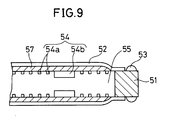
- the membrane-supporting plate 51 of the filtration membrane cartridge 5 incorporates a channel 54 for permeated liquid flowing out of the filtering membranes 52.
- the channel 54 comprises fine meshy grooves 54a or a plurality of slits 54b or grooves 54a and slits 54b by way of combining them.
- the fine meshy grooves 54a are combined with the slits 54b for example. This method is described below.
- the fine meshy grooves 54a are formed on both-side surfaces of the membrane-supporting plate 51. Structurally, a plurality of fine linear grooves 54a are linked with each other in mesh form. These grooves 54a are formed by applying an etching process against a metal mold used for molding the membrane-supporting plate 51. These fine linear grooves 54a are linked with peripheral edges of apertures of the slits 54b. As shown in Figures 7 and 8, these fine linear grooves 54a may be disposed in parallel with or at an oblique angle against the horizontal and vertical sides of the rectangular membrane-supporting plate 51. Although the present embodiment uses the fine meshy grooves 54a, when being combined with the slits 54b, these fine meshy grooves 54a may be arranged in striped pattern.
- each of these fine meshy grooves 54a has less than 1mm of depth, less than 1mm of width, and less than 5mm of intervals between adjoining grooves 54a.
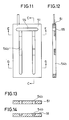
- those slits 54b each having an appropriate depth are respectively open to the surface of the membrane-supporting plate 51 and disposed in parallel with vertical sides of the membrane-supporting plate 51. As shown in Figures 11 through 14, those slits 54b may be formed by way of extending themselves in the direction of the thickness of the membrane-supporting plate 51.
- a sump of permeated liquid 55 is formed at a location close to an end and along widthwise direction of the membrane-supporting plate 51.
- the sump 55 is linked with the fine meshy grooves 54a and the slits 54b at peripheral edges of apertures on the surface of the membrane-supporting plate 51.
- a suction port 56 is formed at the upper end of the membrane-supporting plate 51 so that it can be linked with the sump 55.
- the branch tube 9 routed from the suction tube 8 is connected to the suction port 56.
- a pair of spacers 57 are provided between the membrane-supporting plate 51 and the filtering membranes 52. Each of these spacers 57 provides predetermined interspace between the membrane-supporting plate 51 and the filtering membranes 52 to facilitate permeated liquid to smoothly flow therethrough. Each of these spacers 57 is composed of a felt-like sheet or a plastic net or a metallic net. Each of the filtering membranes 52 has configuration greater than that of the spacer 57 enough to fully cover the spacer 57, and therefore, these spacers 57 are prevented from coming into direct contact with the raw liquid.
- the spacers 57 respectively support the filtering membranes 52 by way of resisting negative pressure caused by permeated liquid suction operation by means of predetermined space formed on the membrane-supporting plate 51, and therefore, permeated liquid out of the filtering membranes 52 can swiftly flow through the predetermined space.
- these spacers 57 are provided in conjunction with permeated liquid channels 54.
- the filtering membranes 52 comprises a thermoplastic non-woven cloth 52a made from saturated polyester resin functioning as the supporting body and a membrane as a surface layer 52b integrated with each other.
- the filtering membrane 52 may be of the one devoid of the non-woven cloth 52a.
- Those spacers 57 are not always essential for embodying the filtration membrane cartridge related to the invention.
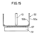
- a horn 13 is set to a predetermined position above the filtering membranes 52 in order to oscillate ultrasonic wave.
- a rotary horn 13 or a stationary horn 13 is usable, where the rotary horn 13 is specifically used when processing compactly composed filtering membranes 52.
- the horn 13 oscillates ultrasonic wave to fusibly bond the filtering membranes 52 to the membrane-supporting plate 51.
- the non-woven cloth 52a functioning as the substrate for supporting the filtering membranes 52 is made from saturated polyester resin
- the non-woven cloth 52a is subject to melting at a temperature above 140° C. for example.
- the membrane-supporting plate 51 is subject to melting at a temperature lower than the melting point of the non-woven cloth 52a in that the membrane-supporting plate 51 is made from ABS resin or the like. Therefore, when applying temperature lower than about 140° C., the membrane-support-ing plate is melted to cause the molten resinous component to infiltrate into the non-woven cloth 52a, thus causing the filtering membranes 52 to be bonded to the membrane-supporting plate 51.
- both the membrane-supporting plate 51 and the non-woven cloth 52a are subject to fusion with each other.
- the filtering membranes 52 can securely be fused with the membrane-supporting plate 51 by means of molten resinous component of the membrane-supporting plate 51 or by effect of the simultaneous fusion of the resious component of the membrane-supporting plate 51 and the filtering membranes 52.
- the filtering membranes 52 can solidly be bonded to the membrane-supporting plate 51 by causing the plastic membrane-supporting plate 51 and the filtering membranes 52 incorporating plastic substrate or either of these to be fused with each other via a thermal treatment or irradiation of ultrasonic wave.
- the membrane-supporting plate 51 and the filtering membranes 52 are fused with each other via the main fusible domain 14a peripherally and linearly provided along peripheral edges of the filtering membranes and the subordinate fusible domains 14b intermittently provided on a single side or on both sides of the main fusible domain 14a.
- the main fusible domain 14a is provided in order to secure water-sealing effect and fundamental bonding strength.
- the subordinate fusible domains 14b are intermittently provided in plural positions in order to prevent the filtering membranes 52 from being wrinkled, and yet, the subordinate fusible domains 14b respectively reinforce the bonding strength between the membrane-supporting plate 51 and the filtering membranes 52. Considering economy of thermal energy and better effect of fusion, it is desired that the main fusible domain 14a be formed with narrow width.
- the embodiment By effect of providing the subordinate fusible domains 14b on the outer side of the main fusible domain 14a, unfused portion of the filtering membranes 52 is protected so that the filtering membranes 52 can fully be prevented from being stripped off from the membrane-supporting plate 51. Nevertheless, in the event that there is no fear of causing the filtering membranes 52 to be stripped off along the peripheral edges, it is possible for the embodiment to confine provision of the subordinate fusible domains 14b solely to the central part of the filtering membranes 52. As shown in Fig. 18, not only the intermittent and linear formation, but the subordinate fusible domains 14b may also be provided in a variety of patterns such as the one being disposed at predetermined intervals for example.
- a plurality of projected fusible domains 51a may integrally be formed on the membrane-supporting plate 51.
- each of the filtering membranes 52 is disposed by way of fully concealing the projected fusible domains 51a, and then, the fusible domains 51a are melted via a thermal treatment or irradiation of ultra-sonic wave before executing a compressive fusing process to fuse the membrane-supporting plate 51 with the filtering membranes 52 at locally melted regions.
- the filtering membranes 52 can securely be bonded to the membrane-supporting plate 51 by way of preventing the main component of the membrane-supporting plate 51 from being melted, and yet, by way of preventing deformation in the periphery of melted regions and subsequent deformation of the filtering membranes 52 from occurrence.
- the above projected fusible domains 51a may also be formed using members having any shape other than that of the membrane-supporting plate 51, like bar-shaped members for example.
Abstract
Description
- The present invention relates to a filtration membrane cartridge used for solid liquid separation. More particularly, the invention relates to a filtration membrane cartridge sharing most essential part of a membrane separation device.
- As shown in Fig. 1, a typical conventional membrane separation device is provided with a
filtering membrane unit 3 which is disposed by way of being submerged in raw liquid pooled in a raw liquid processing tank. The conventionalfiltering membrane unit 3 incorporates a plurality offiltration membrane cartriges 5 inside of anupper casing 4 by vertically aligning them in parallel with each other at prederemined intervals. In addition, agas supply unit 7 is disposed inside of alower casing 6 in order to feed gas such as oxygen, air, or nitrogen gas, to raw liquid in accordance with objective uses. Each of thefiltration membrane cartriges 5 stored in thefiltering membrane unit 3 is internally provided with a permeated-liquid passage connected to a routedtube 9 of asuction tube 8 for sucking permeated liquid, where an end of thesuction tube 8 is linked with asuction pump 10. - While operating the conventional
membrane separation device 1, thesuction pump 10 generates negative pressure against all thefiltration membrane cartridges 5 stored in thefiltering membrane unit 3 in order that permeated liquid can properly be sucked. On the other hand, gas such as oxygen or air (designated by arrowed mark A) is supplied to thegas supply unit 7 from an external source to enable thegas supply unit 7 to jet out bubble flow into space between adjoiningfiltration membrane cartridges 5 in the upward direction from the bottom of the filtering-membrane unit 3. Upwardly flowing bubble generates aerial lifting action to cause tangential flow along the membrane surface, said tangential flow sweeping away deposit on the membrane surface. - Conventionally, each
filtration membrane cartridge 5 stored in themembrane separation device 1 is inserted in a gutter provided inside of each slit plate vertically set in theupper casing 4. However, since eachfiltration membrane cartridge 5 and the inner surface of each gutter remain in contact with each other via substantial surface area, friction is generated between both surfaces to check operator to smoothly insert and take out each of thecartridges 5 into and from the gutter. - Normally, any conventional
filtration membrane cartridge 5 is based on the structure in which an organic filtering membrane is secured onto the surface of a plane rectangular membrane-supporting plate by bonding peripheral domains of the organic filtering membrane to the membrane-supporting plate. On the other hand, when securing the filtering membrane to the membrane-supporting plate with adhesive agent, adhesive strength is variable according to strength, durability, and chemical resistance property of the selected adhesive agent, and therefore, filtering membrane may incidentally be stripped off from the membrane-supporting plate. - Therefore, the object of the invention is to fully solve those problems described above by providing an improved filtration membrane cartridge that can readily be inserted into and removed from a filtering membrane unit and prevent filtering membranes from being stripped off from the membrane-supporting plates.
- To achieve the above object, the improved filtration membrane cartridge accordidng to the invention disposes each filtering membrane on both surfaces of a membrane-supporting plate made of resin and secures edges of the filtering membranes to the membrane-supporting plate by way of fusing both of them or either of them for adhesion therebetween.
- According to the above structure for embodying the invention, each of the accommodated filtering membranes can solidly be secured to the corresponding membrane-supporting plate by way of melting both the filtering membranes and the corresponding membrane-supporting plate or either of them via a thermal fusion or irradiation of ultrasonic waves.
- To embody a better structure of the filtration membrane cartridge according to the invention, each filtering membrane is bonded to the corresponding membrane-supporting plate via a fusing process applied onto the main fusible domain which is peripherally and linearly formed along periphery of the filtering membrane and subordinate fusible domains which are intermittently formed in plural locations along one side or both sides of the main fusible domains.
- According to the above-referred structure for embodying the invention, substantial bonding strength between the filtering membrane and the corresponding membrane-supporting plate is secured by the main fusible domain. Furthermore, bonding strength is reinforced by effect of local fusion applied onto plural subordinate fusible domains.
- According to the above-referred better structure of the filtration membrane cartridge for embodying the invention, the membrane supporting plate has a channel for permeated liquid which are open to the surface of the membrane-supporting plate that faces the corresponding filtering membrane.
- According to the above-refered structure for embodying the invention, even when the filtering membrane is closely pressed against the corresponding membrane-supporting plate by effect of negative pressure caused by liquid sucking operation, permeated liquid can securely flow through a plurality of channels constantly open to the surface of the membrane-supporting plate to enable liquid permeated to swiftly flow through the filtration system.
- According to the above-referred better structure of the filtration membrane cartridge for embodying the invention, a pair of spacers are inserted between the filtering membranes and the corresponding membrane-supporting plate.
- According to the above-referred structure for embodying the invention, in resistance against negative pressure, each spacer supports the corresponding filtering membrane by providing predetermined space on the corresponding membrane-supporting plate to enable liquid filtered out of the filtering membrane to swiftly flow through the predetermined space.
- To achieve the above objects, the invention provides an improved filtration-membrane cartridge. Each of a predetermined number of the inventive filtration-membrane cartridges is inserted in the corresponding gutter of a slit plate provided inside of the filtering-membrane unit. In particular, the invention provides a plurality of projections on peripheral edges (being opposite from the inner surface of the gutter of the slit plate) of the filtration membrane cartridge to enable these projections to slide themselves to come into contact with the inner surface of the gutter provided in the slit plate.
- According to the above-referred structure for embodying the invention, whenever inserting the filtration membrane cartridge into the corresponding gutter and removing it therefrom, the filtration membrane cartridge is slidably brought into contact with the inner surface of the corresponding gutter of the slit plate by effect of plural projections set to peripheral edges of the filtration membrane cartridge. This in turn contracts contact area of the cartridge against the gutter to reduce frictional force to facilitate operator to easily insert and remove the filtration membrane cartridge into and from the filtering membrane unit.
-
- Fig. 1 is an overall perspective view of the filtration membrane cartridge according to an embodiment of the invention;
- Fig. 2 is a plan designating a structure for retaining the filtration membrane cartridge in position according to an embodiment of the invention;
- Fig. 3 is a front view of the filtration membrane cartridge according to an embodiment shown in Fig. 2;
- Fig. 4 is a lateral view of the filtration membrane cartridge according to an embodiment shown in Fig. 2;
- Fig. 5 is a cross-sectional view of the filtration membrane cartridge across arrowed line A - A shown in Fig. 3;
- Fig. 6 is a cross-sectional view of the filtration membrane cartridge across arrowed line B - B shown in Fig. 5;
- Fig. 7 is a schematic pattern of the groove formed in the membrane-supporting plate according to an embodiment of the invention;
- Fig. 8 is another schematic pattern of the groove formed in the membrane-supporting plate according to another embodiment of the invention;
- Fig. 9 is a partially enlarged cross-sectional view of the filtration membrane cartridge according to the invention;
- Fig. 10 is a cross-sectional view designating another example of the disposition of the filtering membrane against the corresponding membrane-supporting plate;
- Fig. 11 is a front view designating another structure of grooves formed in the membrane-supporting plate;
- Fig. 12 is a cross-sectional view of the membrane-supporting plate across arrowed line C - C shown in Fig. 11;
- Fig. 13 is a cross-sectional view of the membrane-supporting plate across arrowed line D - D shown in Fig. 11;
- Fig. 14 is a cross-sectional view of the membrane-supporting plate across arrowed line E - E shown in Fig. 11;
- Fig. 15 is explanatory of a method of bonding a filtering membrane to the corresponding membrane-supporting plate;
- Fig. 16 is a schematic pattern designating a structure of fused domains in the filtration membrane cartridge according to the invention;
- Fig. 17 is a schematic pattern designating another structure of the fused domains in the filtration membrane cartridge accordidng to the invention;
- Fig. 18 is a schematic pattern designating another structure of the fused domains in the filtration membrane cartrige according to the invention; and
- Fig. 19 is explanatory of another method of bonding a filtering membrane to the corresponding membrane-supporting plate.
- Referring now to the accompanying drawins, full details of the improved filtration membrane cartridge according to an embodiment of the invention are described below. Those essential components having function identical to that of the corresponding components shown in Fig. 1 are designated by identical reference numerals, and thus, description of these is deleted.
- Refer now to Figures 2 through 9, in which a plurality of
filtration membrane cartridges 5 are retained by a plurality ofcorresponding slit plates 11 which are accommodated in anupper casing 4 of a filtrationmembrane assembly unit 3. More particularly, as shown in Fig. 1, a plurality ofgutter 12 are formed in eachslit plate 11 at predetermined intervals. A plurality offiltration membrane cartriges 5 are vertically inserted in thecorresponding gutter 12 in parallel with each other. - Each of the
filtration membrane cartridges 5 has a novel structure comprising a pair offiltering membranes 52 each consisting of an organic membrane such as an ultrafiltration membrane or microfiltration membrane, which are disposed on both surfaces of the plane rectangular membrane-supportingplate 51 made from resin such as PVC for example. A pair offiltering membranes 52 are peripherally secured to the corresponding membrane-supportingplate 51 by applying a fusing process. - Although the present embodiment has disposed the
filtering membranes 52 on both surfaces of the corresponding membrane-supportingplate 51, alternatively, as shown in Fig. 10, a single sack-like filteringmembrane 52 may also be disposed by way of fully covering the membrane-supportingplate 51. The novel method of bonding thefiltering membranes 52 to the corresponding membrane-supportingplate 51 will be described later on. - A channel for permeated liquid further inside of the filtering
membranes 52 is linked with abranch tube 9 routed from asuction tube 8 for sucking permeated liqued at one side of the membrane-supportingplate 51 in thefiltration membrane cartridge 5. Raw liquid is filtered by thesefiltration membrane cartridges 5 by effect of negative pressure generated by asuction pump 10 via aliquid suction tube 8. - A plurality of
projections 53 are disposed on peripheral edges of the membrane-supportingplate 51 at predetermined intervals, more particularly, on a pair of parallel sides opposite fromrespective gutter 12 ofrespective slit plates 11. Those pluralfiltration membrane cartriges 5 are secured to the filtering-membrane unit 3 by slidably bringing thoseprojections 53 into contact with inner surface of thecorresponding gutter 12. - Each of these
projections 53 is elliptically shaped in th vertical directin of thefiltration membrane cartridge 5. For example, in order to manufacture thefiltration membrane cartridges 5 having 1000mm of length and 500mm of width, thefiltration membrane cartridge 5 is essentially provided with a number ofprojections 53 each having 5mm of long diameter, 1 to 2mm of short diameter, and 0.5mm of height, by a certain number ranging from 6 to 20 units per surface of thefiltration membrane cartrige 5. - Since those
projections 53 and the inner surface of thegutter 12 come into contact with each other via confined contactable area to cause minimal friction to occur, operator can readily insert and take out eachfiltration membrane cartridge 5 into and from the correspondinggutter 12 of theslit plate 11. - Even though distortion ever occurs in the
filtration membrane cartridge 5 or in theslit plate 11, or if thefiltration membrane cartridge 5 could not easily be inserted or drawn out as a result of inadequate width of thecorresponding gutter 12 provided in theslit plate 11, thefiltration membrane cartridge 5 can properly fit in with thegutter 12 merely by scraping off thoseprojections 53. - The membrane-supporting
plate 51 of thefiltration membrane cartridge 5 incorporates achannel 54 for permeated liquid flowing out of thefiltering membranes 52. Thechannel 54 comprises finemeshy grooves 54a or a plurality ofslits 54b orgrooves 54a and slits 54b by way of combining them. To implement the present embodiment, the finemeshy grooves 54a are combined with theslits 54b for example. This method is described below. - The fine
meshy grooves 54a are formed on both-side surfaces of the membrane-supportingplate 51. Structurally, a plurality of finelinear grooves 54a are linked with each other in mesh form. Thesegrooves 54a are formed by applying an etching process against a metal mold used for molding the membrane-supportingplate 51. These finelinear grooves 54a are linked with peripheral edges of apertures of theslits 54b. As shown in Figures 7 and 8, these finelinear grooves 54a may be disposed in parallel with or at an oblique angle against the horizontal and vertical sides of the rectangular membrane-supportingplate 51. Although the present embodiment uses the finemeshy grooves 54a, when being combined with theslits 54b, these finemeshy grooves 54a may be arranged in striped pattern. Each of these finemeshy grooves 54a has less than 1mm of depth, less than 1mm of width, and less than 5mm of intervals between adjoininggrooves 54a. On the other hand, thoseslits 54b each having an appropriate depth are respectively open to the surface of the membrane-supportingplate 51 and disposed in parallel with vertical sides of the membrane-supportingplate 51. As shown in Figures 11 through 14, thoseslits 54b may be formed by way of extending themselves in the direction of the thickness of the membrane-supportingplate 51. A sump of permeatedliquid 55 is formed at a location close to an end and along widthwise direction of the membrane-supportingplate 51. Thesump 55 is linked with the finemeshy grooves 54a and theslits 54b at peripheral edges of apertures on the surface of the membrane-supportingplate 51. Asuction port 56 is formed at the upper end of the membrane-supportingplate 51 so that it can be linked with thesump 55. Thebranch tube 9 routed from thesuction tube 8 is connected to thesuction port 56. - When activating the
suction pump 10 to apply negative pressure to thefiltration membrane cartridge 5 via thesuction tube 8, permeated liquid is sucked into thefiltration membrane cartridge 5, and then permeated liquid out of thefiltering membranes 52 flows into thesump 55 via those finemeshy grooves 54a and thoseslits 54b formed inside of themembrane supporting plate 51 to flow into thebranch tube 9 of thesuction tube 8 from thesuction port 56. - While the above processes are underway, even though the
filtering membranes 52 closely adhere to the membrane-supportingplate 51 by effect of negative pressure, since flow of permeated liquid on the surface of the membrane-supportingplate 51 can be secured by means of the finemeshy grooves 54a and theslits 54b, permeated liquid can easily flow through space between the filteringmembranes 52 and the membrane-supportingplate 51. Especially, where slits 54b are formed, the distance of the flow of permeated liquid in the finemeshy grooves 54a shortens, facilitating smoother flow of the liquid. - A pair of
spacers 57 are provided between the membrane-supportingplate 51 and thefiltering membranes 52. Each of thesespacers 57 provides predetermined interspace between the membrane-supportingplate 51 and thefiltering membranes 52 to facilitate permeated liquid to smoothly flow therethrough. Each of thesespacers 57 is composed of a felt-like sheet or a plastic net or a metallic net. Each of thefiltering membranes 52 has configuration greater than that of thespacer 57 enough to fully cover thespacer 57, and therefore, thesespacers 57 are prevented from coming into direct contact with the raw liquid. - According to the structure described above, since the
spacers 57 respectively support thefiltering membranes 52 by way of resisting negative pressure caused by permeated liquid suction operation by means of predetermined space formed on the membrane-supportingplate 51, and therefore, permeated liquid out of thefiltering membranes 52 can swiftly flow through the predetermined space. When implementing the present embodiment, thesespacers 57 are provided in conjunction with permeatedliquid channels 54. However, it is also practicable for the embodiment to solely provide thesespacers 57 by way of deleting the permeatedliquid channels 54. - Next, the method of fusibly bonding the
filtering membranes 52 to the membrane-supportingplate 51 is described below.As shown in Fig. 15, the membrane-supportingplate 51, thefiltering membranes 52, and thespacers 57, are superposed in sequence. In the present embodiment, thefiltering membranes 52 comprises a thermoplasticnon-woven cloth 52a made from saturated polyester resin functioning as the supporting body and a membrane as asurface layer 52b integrated with each other. However, thefiltering membrane 52 may be of the one devoid of thenon-woven cloth 52a. Thosespacers 57 are not always essential for embodying the filtration membrane cartridge related to the invention. - After superposing those components mentioned above, a
horn 13 is set to a predetermined position above thefiltering membranes 52 in order to oscillate ultrasonic wave. Either arotary horn 13 or astationary horn 13 is usable, where therotary horn 13 is specifically used when processing compactly composedfiltering membranes 52. On the way of moving over thefiltering membranes 52, thehorn 13 oscillates ultrasonic wave to fusibly bond thefiltering membranes 52 to the membrane-supportingplate 51. - As mentioned above, since the
non-woven cloth 52a functioning as the substrate for supporting thefiltering membranes 52 is made from saturated polyester resin, thenon-woven cloth 52a is subject to melting at a temperature above 140° C. for example. On the other hand, the membrane-supportingplate 51 is subject to melting at a temperature lower than the melting point of thenon-woven cloth 52a in that the membrane-supportingplate 51 is made from ABS resin or the like. Therefore, when applying temperature lower than about 140° C., the membrane-support-ing plate is melted to cause the molten resinous component to infiltrate into thenon-woven cloth 52a, thus causing thefiltering membranes 52 to be bonded to the membrane-supportingplate 51. - On exposure to temperature higher than about 140° C., both the membrane-supporting
plate 51 and thenon-woven cloth 52a are subject to fusion with each other. - Even when thermally treating the
filtering membranes 52 devoid of thenon-woven cloth 52a, thefiltering membranes 52 can securely be fused with the membrane-supportingplate 51 by means of molten resinous component of the membrane-supportingplate 51 or by effect of the simultaneous fusion of the resious component of the membrane-supportingplate 51 and thefiltering membranes 52. - On the way of executing the thermal fusion process by applying ultrasonic wave, objective resinous component is apt to melt from the inner domain, and thus, it is desired that the
horn 13 be activated via a thermally resistant tape disposed on thefiltering membranes 52. Instead of the above fusing method using ultrasonioc wave, local thermal treatment can also be performed for locally fusing thefiltering membranes 52 with the membrane-supportingplate 51. - As described above, the
filtering membranes 52 can solidly be bonded to the membrane-supportingplate 51 by causing the plastic membrane-supportingplate 51 and thefiltering membranes 52 incorporating plastic substrate or either of these to be fused with each other via a thermal treatment or irradiation of ultrasonic wave. - As shown in Figures 16 and 17, the membrane-supporting
plate 51 and thefiltering membranes 52 are fused with each other via the mainfusible domain 14a peripherally and linearly provided along peripheral edges of the filtering membranes and the subordinatefusible domains 14b intermittently provided on a single side or on both sides of the mainfusible domain 14a. - The main
fusible domain 14a is provided in order to secure water-sealing effect and fundamental bonding strength. On the other hand, the subordinatefusible domains 14b are intermittently provided in plural positions in order to prevent thefiltering membranes 52 from being wrinkled, and yet, the subordinatefusible domains 14b respectively reinforce the bonding strength between the membrane-supportingplate 51 and thefiltering membranes 52. Considering economy of thermal energy and better effect of fusion, it is desired that the mainfusible domain 14a be formed with narrow width. By effect of providing the subordinatefusible domains 14b on the outer side of the mainfusible domain 14a, unfused portion of thefiltering membranes 52 is protected so that thefiltering membranes 52 can fully be prevented from being stripped off from the membrane-supportingplate 51. Nevertheless, in the event that there is no fear of causing thefiltering membranes 52 to be stripped off along the peripheral edges, it is possible for the embodiment to confine provision of the subordinatefusible domains 14b solely to the central part of thefiltering membranes 52. As shown in Fig. 18, not only the intermittent and linear formation, but the subordinatefusible domains 14b may also be provided in a variety of patterns such as the one being disposed at predetermined intervals for example. - As shown in Fig. 19 for example, prior to the execution of a fusion process between the membrane-supporting
plate 51 and thefiltering membranes 52, a plurality of projectedfusible domains 51a may integrally be formed on the membrane-supportingplate 51. When implementing this method, initially, each of thefiltering membranes 52 is disposed by way of fully concealing the projectedfusible domains 51a, and then, thefusible domains 51a are melted via a thermal treatment or irradiation of ultra-sonic wave before executing a compressive fusing process to fuse the membrane-supportingplate 51 with thefiltering membranes 52 at locally melted regions. - As a result of the provision of the above structure, the
filtering membranes 52 can securely be bonded to the membrane-supportingplate 51 by way of preventing the main component of the membrane-supportingplate 51 from being melted, and yet, by way of preventing deformation in the periphery of melted regions and subsequent deformation of thefiltering membranes 52 from occurrence. The above projectedfusible domains 51a may also be formed using members having any shape other than that of the membrane-supportingplate 51, like bar-shaped members for example.
Claims (5)
- A filtration membrane cartridge comprising;
a plurality of filtering membranes disposed on both surfaces of a resin membrane-supporting plate; wherein said filtering membranes are individually fused with said membrane-suporting plate at edges of said filtering membranes. - The filtration membrane cartridge as defined in Claim 1, wherein each of said filtering membranes is bonded to said membrane-supporting plate at a main bondable domain which is peripherally and linearly formed along peripheral edges of each of said filtering membranes and at a plurality of subordinate fusible domains intermittently formed in plural local regions on one side or on both sides of said main fusible domain.
- The filtration membrane cartridge as defined in Claim 1, wherein said membrane-supporting plate incorporates a plurality of channels for permeated liquid respectively being open to surface of said membrane-supporting plate facing said filtering membranes.
- The filtration membrane cartridge as defined in Claim 1, wherein a plurality of spacers are respectively interposed between said filtering membranes and said membrane-supporting plate.
- A filtration membrane cartridge which is disposed by way of being inserted in each gutter of a slit plate provided in a filtration membrane assembly unit wherein comprising;
a plurality of projections formed on peripheral edges of each filtration membrane cartridge facing inner surface of each gutter formed inside of slit plate, wherein said projections respectively come into contact with said inner surface of said gutter by way of sliding themselves.
Applications Claiming Priority (8)
| Application Number | Priority Date | Filing Date | Title |
|---|---|---|---|
| JP33479192A JP2897799B2 (en) | 1992-12-16 | 1992-12-16 | Filtration membrane module |
| JP334791/92 | 1992-12-16 | ||
| JP800093A JP2943832B2 (en) | 1993-01-21 | 1993-01-21 | Filtration membrane module |
| JP8000/93 | 1993-01-21 | ||
| JP5176318A JP3028900B2 (en) | 1993-07-16 | 1993-07-16 | Manufacturing method of membrane element |
| JP176318/93 | 1993-07-16 | ||
| JP176317/93 | 1993-07-16 | ||
| JP5176317A JP3010979B2 (en) | 1993-07-16 | 1993-07-16 | Welding method of membrane element |
Publications (2)
| Publication Number | Publication Date |
|---|---|
| EP0602560A1 true EP0602560A1 (en) | 1994-06-22 |
| EP0602560B1 EP0602560B1 (en) | 1998-08-12 |
Family
ID=27454843
Family Applications (1)
| Application Number | Title | Priority Date | Filing Date |
|---|---|---|---|
| EP93119930A Expired - Lifetime EP0602560B1 (en) | 1992-12-16 | 1993-12-10 | Filtration membrane cartridge |
Country Status (8)
| Country | Link |
|---|---|
| EP (1) | EP0602560B1 (en) |
| AU (1) | AU655551B2 (en) |
| CA (1) | CA2110971C (en) |
| DE (1) | DE69320311T2 (en) |
| ES (1) | ES2121922T3 (en) |
| NO (1) | NO305109B1 (en) |
| SG (1) | SG42331A1 (en) |
| TW (1) | TW235926B (en) |
Cited By (15)
| Publication number | Priority date | Publication date | Assignee | Title |
|---|---|---|---|---|
| EP0653240A1 (en) * | 1993-05-17 | 1995-05-17 | Kubota Corporation | Filtration film element and method of manufacturing the same |
| EP0662341A1 (en) * | 1994-01-07 | 1995-07-12 | Kubota Corporation | Filtration membrane module |
| WO1998001219A1 (en) * | 1996-07-09 | 1998-01-15 | Teijin Limited | A filter member |
| US5772831A (en) * | 1995-04-03 | 1998-06-30 | Kubota Corporation | Filter membrane element and method of manufacturing same |
| EP0937494A2 (en) * | 1998-02-23 | 1999-08-25 | Kubota Corporation | Membrane separation system |
| WO2006044712A1 (en) * | 2004-10-14 | 2006-04-27 | Pall Corporation | Separation elements and methods of making separation elements |
| WO2006027560A3 (en) * | 2004-09-10 | 2006-06-08 | Brightwater Engineering Ltd | Apparatus and method |
| US7279215B2 (en) | 2003-12-03 | 2007-10-09 | 3M Innovative Properties Company | Membrane modules and integrated membrane cassettes |
| WO2007128565A2 (en) | 2006-05-08 | 2007-11-15 | Itn Nanovation Ag | Immersion filter unit for wastewater treatment and production of drinking water |
| WO2009069295A1 (en) | 2007-11-28 | 2009-06-04 | Kubota Corporation | Membrane cartridge |
| DE102008036920A1 (en) | 2008-08-04 | 2010-02-11 | Itn Nanovation Ag | Filtration unit for the treatment of water |
| WO2012060689A1 (en) * | 2010-11-03 | 2012-05-10 | Moon Tuck Mak | Water filtration apparatus with automatic backwash |
| DE102011087338A1 (en) | 2011-11-29 | 2013-05-29 | Ltn Nanovation Ag | Cryogenic stable filtration unit and its preparation |
| WO2013113928A1 (en) | 2012-02-03 | 2013-08-08 | Vito Nv (Vlaamse Instelling Voor Technologisch Onderzoek Nv) | Backwashable filtration element |
| US11092977B1 (en) | 2017-10-30 | 2021-08-17 | Zane Coleman | Fluid transfer component comprising a film with fluid channels |
Families Citing this family (1)
| Publication number | Priority date | Publication date | Assignee | Title |
|---|---|---|---|---|
| US6986428B2 (en) | 2003-05-14 | 2006-01-17 | 3M Innovative Properties Company | Fluid separation membrane module |
Citations (5)
| Publication number | Priority date | Publication date | Assignee | Title |
|---|---|---|---|---|
| DE2303860A1 (en) * | 1972-01-28 | 1973-08-02 | Rhone Poulenc Sa | MEMBRANE SEPARATION DEVICE |
| FR2478483A1 (en) * | 1979-11-05 | 1981-09-25 | Millipore Corp | Discardable filter cartridge - has stack of units with membranes sealed to ribbed supports |
| DE3726865A1 (en) * | 1986-08-12 | 1988-02-18 | Fuji Photo Film Co Ltd | FILTER CARTRIDGE |
| DE3728825A1 (en) | 1986-08-28 | 1988-03-03 | Fuji Photo Film Co Ltd | FILTER CARTRIDGE |
| EP0457676A2 (en) | 1990-05-15 | 1991-11-21 | Eurodia Industrie Sa | Process for the manufacture of a separator plate for a stack in an exchange device |
Family Cites Families (1)
| Publication number | Priority date | Publication date | Assignee | Title |
|---|---|---|---|---|
| US4501663A (en) * | 1979-11-05 | 1985-02-26 | Millipore Corporation | Filter cartridges and methods and components for making them |
-
1993
- 1993-12-03 AU AU52163/93A patent/AU655551B2/en not_active Ceased
- 1993-12-08 CA CA002110971A patent/CA2110971C/en not_active Expired - Fee Related
- 1993-12-08 TW TW082110384A patent/TW235926B/zh not_active IP Right Cessation
- 1993-12-10 DE DE69320311T patent/DE69320311T2/en not_active Expired - Lifetime
- 1993-12-10 ES ES93119930T patent/ES2121922T3/en not_active Expired - Lifetime
- 1993-12-10 EP EP93119930A patent/EP0602560B1/en not_active Expired - Lifetime
- 1993-12-10 SG SG1996000783A patent/SG42331A1/en unknown
- 1993-12-15 NO NO934620A patent/NO305109B1/en unknown
Patent Citations (5)
| Publication number | Priority date | Publication date | Assignee | Title |
|---|---|---|---|---|
| DE2303860A1 (en) * | 1972-01-28 | 1973-08-02 | Rhone Poulenc Sa | MEMBRANE SEPARATION DEVICE |
| FR2478483A1 (en) * | 1979-11-05 | 1981-09-25 | Millipore Corp | Discardable filter cartridge - has stack of units with membranes sealed to ribbed supports |
| DE3726865A1 (en) * | 1986-08-12 | 1988-02-18 | Fuji Photo Film Co Ltd | FILTER CARTRIDGE |
| DE3728825A1 (en) | 1986-08-28 | 1988-03-03 | Fuji Photo Film Co Ltd | FILTER CARTRIDGE |
| EP0457676A2 (en) | 1990-05-15 | 1991-11-21 | Eurodia Industrie Sa | Process for the manufacture of a separator plate for a stack in an exchange device |
Cited By (25)
| Publication number | Priority date | Publication date | Assignee | Title |
|---|---|---|---|---|
| EP0653240A1 (en) * | 1993-05-17 | 1995-05-17 | Kubota Corporation | Filtration film element and method of manufacturing the same |
| EP0653240A4 (en) * | 1993-05-17 | 1995-11-22 | Kubota Kk | Filtration film element and method of manufacturing the same. |
| EP0662341A1 (en) * | 1994-01-07 | 1995-07-12 | Kubota Corporation | Filtration membrane module |
| US5772831A (en) * | 1995-04-03 | 1998-06-30 | Kubota Corporation | Filter membrane element and method of manufacturing same |
| WO1998001219A1 (en) * | 1996-07-09 | 1998-01-15 | Teijin Limited | A filter member |
| EP0937494A2 (en) * | 1998-02-23 | 1999-08-25 | Kubota Corporation | Membrane separation system |
| EP0937494A3 (en) * | 1998-02-23 | 2000-03-01 | Kubota Corporation | Membrane separation system |
| US7279215B2 (en) | 2003-12-03 | 2007-10-09 | 3M Innovative Properties Company | Membrane modules and integrated membrane cassettes |
| WO2006027560A3 (en) * | 2004-09-10 | 2006-06-08 | Brightwater Engineering Ltd | Apparatus and method |
| WO2006044712A1 (en) * | 2004-10-14 | 2006-04-27 | Pall Corporation | Separation elements and methods of making separation elements |
| WO2007128565A2 (en) | 2006-05-08 | 2007-11-15 | Itn Nanovation Ag | Immersion filter unit for wastewater treatment and production of drinking water |
| WO2007128565A3 (en) * | 2006-05-08 | 2008-02-07 | Itn Nanovation Ag | Immersion filter unit for wastewater treatment and production of drinking water |
| WO2009069295A1 (en) | 2007-11-28 | 2009-06-04 | Kubota Corporation | Membrane cartridge |
| EP2228125A1 (en) * | 2007-11-28 | 2010-09-15 | Kubota Corporation | Membrane cartridge |
| EP2228125A4 (en) * | 2007-11-28 | 2012-08-22 | Kubota Kk | Membrane cartridge |
| US8647507B2 (en) | 2007-11-28 | 2014-02-11 | Kubota Corporation | Membrane cartridge |
| DE102008036920A1 (en) | 2008-08-04 | 2010-02-11 | Itn Nanovation Ag | Filtration unit for the treatment of water |
| WO2010015374A1 (en) | 2008-08-04 | 2010-02-11 | Itn Nanovation Ag | Filter unit for treating water and other liquid media |
| US8709252B2 (en) | 2008-08-04 | 2014-04-29 | Itn Nanovation Ag | Filter unit for treating water and other liquid media |
| WO2012060689A1 (en) * | 2010-11-03 | 2012-05-10 | Moon Tuck Mak | Water filtration apparatus with automatic backwash |
| DE102011087338A1 (en) | 2011-11-29 | 2013-05-29 | Ltn Nanovation Ag | Cryogenic stable filtration unit and its preparation |
| WO2013079392A1 (en) | 2011-11-29 | 2013-06-06 | Itn Nanovation Ag | Low-temperature-stable filtration unit and the production thereof |
| WO2013113928A1 (en) | 2012-02-03 | 2013-08-08 | Vito Nv (Vlaamse Instelling Voor Technologisch Onderzoek Nv) | Backwashable filtration element |
| US9919273B2 (en) | 2012-02-03 | 2018-03-20 | Vito Nv (Vlaamse Instelling Voor Technologisch Onderzoek Nv) | Backwashable filtration element |
| US11092977B1 (en) | 2017-10-30 | 2021-08-17 | Zane Coleman | Fluid transfer component comprising a film with fluid channels |
Also Published As
| Publication number | Publication date |
|---|---|
| EP0602560B1 (en) | 1998-08-12 |
| SG42331A1 (en) | 1997-08-15 |
| ES2121922T3 (en) | 1998-12-16 |
| AU5216393A (en) | 1994-06-30 |
| DE69320311D1 (en) | 1998-09-17 |
| NO934620D0 (en) | 1993-12-15 |
| NO305109B1 (en) | 1999-04-06 |
| CA2110971C (en) | 2000-04-25 |
| NO934620L (en) | 1994-06-17 |
| CA2110971A1 (en) | 1994-06-17 |
| AU655551B2 (en) | 1994-12-22 |
| DE69320311T2 (en) | 1999-03-11 |
| TW235926B (en) | 1994-12-11 |
Similar Documents
| Publication | Publication Date | Title |
|---|---|---|
| US5651888A (en) | Filtration membrane cartridge | |
| EP0602560A1 (en) | Filtration membrane cartridge | |
| JP5079984B2 (en) | Membrane element manufacturing method | |
| KR101892223B1 (en) | Formed sheet membrane element and filtration system | |
| KR100564841B1 (en) | Microstructured separation device | |
| EP0820343B1 (en) | Method of making filter cartridges having track etched membranes | |
| EP1366804B1 (en) | Method of replacement of a filtration membrane of a filtration cartridge for activated sludge | |
| US7097800B2 (en) | Process for making a fluid processing module | |
| US20050184001A1 (en) | Filtration module | |
| JP2008049239A (en) | Membrane element | |
| US7264724B2 (en) | Fluid path control element for fluid processing module | |
| JP6212757B2 (en) | Liquid processing apparatus and method for manufacturing liquid processing apparatus | |
| CN1033491C (en) | Filtration membrane cartridge | |
| JP2008073678A (en) | Cartridge for filtration | |
| JP3028900B2 (en) | Manufacturing method of membrane element | |
| WO1994026398A1 (en) | Filtration film element and method of manufacturing the same | |
| JP3603596B2 (en) | Immersion type flat membrane separator | |
| JP3160660B2 (en) | Filtration material for solid-liquid separation of sewage, wastewater, etc. | |
| JPH06277463A (en) | Membrane separation device | |
| JPH09290140A (en) | Membrane module | |
| JPH0829206B2 (en) | Filter element manufacturing method | |
| JPH0713785Y2 (en) | Filter element | |
| JPH11333264A (en) | Membrane element and membrane separation device using the element | |
| JPH11319512A (en) | Membrane element | |
| JPH03207416A (en) | Filter body |
Legal Events
| Date | Code | Title | Description |
|---|---|---|---|
| PUAI | Public reference made under article 153(3) epc to a published international application that has entered the european phase |
Free format text: ORIGINAL CODE: 0009012 |
|
| AK | Designated contracting states |
Kind code of ref document: A1 Designated state(s): BE CH DE ES FR GB IT LI NL SE |
|
| 17P | Request for examination filed |
Effective date: 19941010 |
|
| 17Q | First examination report despatched |
Effective date: 19960322 |
|
| GRAG | Despatch of communication of intention to grant |
Free format text: ORIGINAL CODE: EPIDOS AGRA |
|
| GRAG | Despatch of communication of intention to grant |
Free format text: ORIGINAL CODE: EPIDOS AGRA |
|
| GRAH | Despatch of communication of intention to grant a patent |
Free format text: ORIGINAL CODE: EPIDOS IGRA |
|
| GRAH | Despatch of communication of intention to grant a patent |
Free format text: ORIGINAL CODE: EPIDOS IGRA |
|
| GRAA | (expected) grant |
Free format text: ORIGINAL CODE: 0009210 |
|
| ITF | It: translation for a ep patent filed |
Owner name: DE DOMINICIS & MAYER S.R.L. |
|
| AK | Designated contracting states |
Kind code of ref document: B1 Designated state(s): BE CH DE ES FR GB IT LI NL SE |
|
| REG | Reference to a national code |
Ref country code: CH Ref legal event code: NV Representative=s name: E. BLUM & CO. PATENTANWAELTE Ref country code: CH Ref legal event code: EP |
|
| REF | Corresponds to: |
Ref document number: 69320311 Country of ref document: DE Date of ref document: 19980917 |
|
| ET | Fr: translation filed | ||
| REG | Reference to a national code |
Ref country code: ES Ref legal event code: FG2A Ref document number: 2121922 Country of ref document: ES Kind code of ref document: T3 |
|
| PGFP | Annual fee paid to national office [announced via postgrant information from national office to epo] |
Ref country code: BE Payment date: 19981222 Year of fee payment: 6 |
|
| PGFP | Annual fee paid to national office [announced via postgrant information from national office to epo] |
Ref country code: SE Payment date: 19981223 Year of fee payment: 6 |
|
| PGFP | Annual fee paid to national office [announced via postgrant information from national office to epo] |
Ref country code: CH Payment date: 19990108 Year of fee payment: 6 |
|
| PLBE | No opposition filed within time limit |
Free format text: ORIGINAL CODE: 0009261 |
|
| STAA | Information on the status of an ep patent application or granted ep patent |
Free format text: STATUS: NO OPPOSITION FILED WITHIN TIME LIMIT |
|
| PG25 | Lapsed in a contracting state [announced via postgrant information from national office to epo] |
Ref country code: NL Free format text: LAPSE BECAUSE OF NON-PAYMENT OF DUE FEES Effective date: 19990701 |
|
| 26N | No opposition filed | ||
| NLV4 | Nl: lapsed or anulled due to non-payment of the annual fee |
Effective date: 19990701 |
|
| PG25 | Lapsed in a contracting state [announced via postgrant information from national office to epo] |
Ref country code: SE Free format text: LAPSE BECAUSE OF NON-PAYMENT OF DUE FEES Effective date: 19991211 |
|
| PG25 | Lapsed in a contracting state [announced via postgrant information from national office to epo] |
Ref country code: LI Free format text: LAPSE BECAUSE OF NON-PAYMENT OF DUE FEES Effective date: 19991231 Ref country code: CH Free format text: LAPSE BECAUSE OF NON-PAYMENT OF DUE FEES Effective date: 19991231 Ref country code: BE Free format text: LAPSE BECAUSE OF NON-PAYMENT OF DUE FEES Effective date: 19991231 |
|
| BERE | Be: lapsed |
Owner name: KUBOTA CORP. Effective date: 19991231 |
|
| EUG | Se: european patent has lapsed |
Ref document number: 93119930.1 |
|
| REG | Reference to a national code |
Ref country code: GB Ref legal event code: IF02 |
|
| PGFP | Annual fee paid to national office [announced via postgrant information from national office to epo] |
Ref country code: ES Payment date: 20091229 Year of fee payment: 17 |
|
| PGFP | Annual fee paid to national office [announced via postgrant information from national office to epo] |
Ref country code: IT Payment date: 20091222 Year of fee payment: 17 Ref country code: GB Payment date: 20091209 Year of fee payment: 17 Ref country code: FR Payment date: 20091221 Year of fee payment: 17 |
|
| PGFP | Annual fee paid to national office [announced via postgrant information from national office to epo] |
Ref country code: DE Payment date: 20091203 Year of fee payment: 17 |
|
| GBPC | Gb: european patent ceased through non-payment of renewal fee |
Effective date: 20101210 |
|
| REG | Reference to a national code |
Ref country code: FR Ref legal event code: ST Effective date: 20110831 |
|
| PG25 | Lapsed in a contracting state [announced via postgrant information from national office to epo] |
Ref country code: FR Free format text: LAPSE BECAUSE OF NON-PAYMENT OF DUE FEES Effective date: 20110103 |
|
| REG | Reference to a national code |
Ref country code: DE Ref legal event code: R119 Ref document number: 69320311 Country of ref document: DE Effective date: 20110701 |
|
| PG25 | Lapsed in a contracting state [announced via postgrant information from national office to epo] |
Ref country code: DE Free format text: LAPSE BECAUSE OF NON-PAYMENT OF DUE FEES Effective date: 20110701 Ref country code: GB Free format text: LAPSE BECAUSE OF NON-PAYMENT OF DUE FEES Effective date: 20101210 |
|
| PG25 | Lapsed in a contracting state [announced via postgrant information from national office to epo] |
Ref country code: IT Free format text: LAPSE BECAUSE OF NON-PAYMENT OF DUE FEES Effective date: 20101210 |
|
| REG | Reference to a national code |
Ref country code: ES Ref legal event code: FD2A Effective date: 20120206 |
|
| PG25 | Lapsed in a contracting state [announced via postgrant information from national office to epo] |
Ref country code: ES Free format text: LAPSE BECAUSE OF NON-PAYMENT OF DUE FEES Effective date: 20101211 |