EP0602501B1 - Flexible sealing of the gap between the edge of an opening in a building and the rear of a vehicle drawn up to the same - Google Patents
Flexible sealing of the gap between the edge of an opening in a building and the rear of a vehicle drawn up to the same Download PDFInfo
- Publication number
- EP0602501B1 EP0602501B1 EP93119657A EP93119657A EP0602501B1 EP 0602501 B1 EP0602501 B1 EP 0602501B1 EP 93119657 A EP93119657 A EP 93119657A EP 93119657 A EP93119657 A EP 93119657A EP 0602501 B1 EP0602501 B1 EP 0602501B1
- Authority
- EP
- European Patent Office
- Prior art keywords
- seal according
- building
- strips
- deformable
- seal
- Prior art date
- Legal status (The legal status is an assumption and is not a legal conclusion. Google has not performed a legal analysis and makes no representation as to the accuracy of the status listed.)
- Expired - Lifetime
Links
Images
Classifications
-
- B—PERFORMING OPERATIONS; TRANSPORTING
- B65—CONVEYING; PACKING; STORING; HANDLING THIN OR FILAMENTARY MATERIAL
- B65G—TRANSPORT OR STORAGE DEVICES, e.g. CONVEYORS FOR LOADING OR TIPPING, SHOP CONVEYOR SYSTEMS OR PNEUMATIC TUBE CONVEYORS
- B65G69/00—Auxiliary measures taken, or devices used, in connection with loading or unloading
- B65G69/008—Dock- or bumper-seals
Definitions
- the invention relates to a deformable seal of the gap between the edge of a building opening and the rear of a vehicle approaching it with a lobed, deformable apron made of two vertical strips arranged on both sides of the building opening and a transverse part located in the area of the upper strip ends, from which a roof tarpaulin extends toward the rear of the building, the two strips being attached at their lateral outer edges with the front edge to deformable side parts anchored at the rear of the building and the side parts with the strips ending at a distance from the roof tarpaulin, that the two strips and the side parts are deformable independently of the cross part when subjected to a vehicle.
- the side parts are designed as foam packs or strong springs and are thus designed so that they are self-supporting.
- This compact design means that the seal is not easily deformable enough to adapt to the rear shape of the vehicle.
- the side parts are lobed, easily deformable, not inherently rigid tarpaulins, which are suspended by means of flexible, flexible brackets which engage at their upper ends and which have flexible, flexible expansion means at their lower ends.
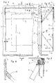
- the wall 1 of a building e.g. of a warehouse has a building opening 2 which e.g. can be closed by a sectional door.
- a deformable seal according to the drawing is provided in order to be able to carry out a charging operation without major adverse weather effects.
- a deformable apron which consists of an upper transverse part 3 and two perpendicular strips 4 located on both sides of the building opening 2.
- the cross member 3 located in front of the strips 4 is suspended like a curtain and connected at the top with a rigid cross-member 5, which is supported by struts 6 directed obliquely upwards.
- a metal profile 7 is attached, which serves to suspend the cross member 3 and a roof tarpaulin 8, which is attached to the wall 1 with its rear end.
- the two struts 6 arranged in the region of the ends of the transverse part 3 are rigidly connected to the crossmember 5, but the struts 6 can be pivoted on a sliding block 8 at the lower end and can thus be moved in the direction of the arrow 9.
- the sliding block 8 can perform lifting movements on vertical guides 10, which are fastened to the wall 1. Accordingly, the cross member 3 with the cross member 5 and the roof tarpaulin 8 can perform lifting movements, e.g. with comparatively high vehicles or with lifting movements of semi-trailers are necessary.
- Overhangs 11 are provided at both ends of the roof tarpaulin 8 as freely hanging rags.
- the side parts 12 sealing the outside of the seal are of particular importance. They are attached with one edge to the wall 1 and with the other edge to a vertical edge profile 13, which in turn carries the vertical strips 4.
- the side parts 12 thus seal the distance between the wall 1 and the side edges of the strips 4.
- the parts 4, 12 - like the parts 3, 8 and 11 - are made of a lobed, film-like material that conforms to the contour Can adapt vehicle, in total but is tensile and tear resistant. A fabric coated with rubber or plastic can be used.
- the side parts 12 are not held by load-bearing, attached to the wall 1 handlebars, rather they are carried only by approximately in the region of the edge profiles 13 at 14 attacking ropes 15 which are passed through the cross member 5, are deflected there with rollers 16 and finally over a hidden tension spring 17 are connected.
- the inner corners of the strips 4 are connected by an elastic cable 18a, although the strips 4 can also be intercepted by upward elastic cables - attached to the cross member 5.
- the lower end of a very tightly wound helical spring 18 is firmly connected to it, which rises at an angle of approximately 30 ° to 60 ° with respect to the vertical. It is also firmly connected to the wall 1 at the upper end.
- the peculiarity of the mentioned helical spring 18 is also that it counteracts lateral forces by elastic bending. Skewing forces, which generally arise when a vehicle acts on it, therefore lead to an elastic deformation of the entire apron including side parts 12. When the vehicle leaves the seal, the coil spring 18 returns to its elongated shape and tightens the side parts 12 in the process .
- the strut in the form of the coil spring 18 thus has practically no supporting function with regard to the weight load by the strips 4 and the side parts 12; the necessary forces are rather practically absorbed by the tension spring 17.
- the helical spring 18 can be replaced by a strut which also runs in the sense of the helical spring 18 and which can consist of a metal rod or the like, but which must be articulated at both ends to the wall or the edge profile 13.
- a strut which also runs in the sense of the helical spring 18 and which can consist of a metal rod or the like, but which must be articulated at both ends to the wall or the edge profile 13.
- the strut thus designed can be shortened in length, for example, by means of a telescopic design, specifically against the action of a spring which has to restore the state according to the drawing again and again and thus accomplishes the spreading and tightening of the side parts 12.
Abstract
Description
Die Erfindung betrifft eine verformbare Dichtung des Spaltes zwischen dem Rand einer Gebäudeöffnung und dem Heck eines an diese herangefahrenen Fahrzeuges mit einer lappigen, verformbaren Schürze aus zwei zu beiden Seiten der Gebäudeöffnung angeordneten senkrechten Streifen und einem im Bereich der oberen Streifenenden befindlichen Querteil, von dem aus sich nach hinten zum Gebäude hin eine Dachplane erstreckt, wobei die beiden Streifen an ihren seitlich aussen gelegenen Rändern mit dem vorderen Rand an verformbaren, hinten am Gebäude verankerten Seitenteilen befestigt sind und die Seitenteile mit den Streifen im Abstand von der Dachplane enden in der Weise, dass die beiden Streifen und die Seitenteile bei einer Beaufschlagung durch ein Fahrzeug unabhängig von dem Querteil verformbar sind.The invention relates to a deformable seal of the gap between the edge of a building opening and the rear of a vehicle approaching it with a lobed, deformable apron made of two vertical strips arranged on both sides of the building opening and a transverse part located in the area of the upper strip ends, from which a roof tarpaulin extends toward the rear of the building, the two strips being attached at their lateral outer edges with the front edge to deformable side parts anchored at the rear of the building and the side parts with the strips ending at a distance from the roof tarpaulin, that the two strips and the side parts are deformable independently of the cross part when subjected to a vehicle.
Bei den bekannten Dichtungen dieser Ausbildung sind die Seitenteile als Schaumstoffpakete oder starke Federn ausgebildet und somit so ausgebildet, dass sie selbsttragend sind. Diese kompakte Bauweise hat zur Folge, dass eine leichte Verformbarkeit der Dichtung zur Anpassung an die Heckgestalt des Fahrzeuges nicht immer in ausreichendem Masse gegeben ist.In the known seals of this design, the side parts are designed as foam packs or strong springs and are thus designed so that they are self-supporting. This compact design means that the seal is not easily deformable enough to adapt to the rear shape of the vehicle.
Aufgrund der Erfindung sollen diese Nachteile beseitigt werden; durch eine besondere Ausbildung der Seitenteile und ihrer Halterungen sollen die Konstruktion vereinfacht und die Verformbarkeit verbessert werden.These disadvantages are to be eliminated on the basis of the invention; a special design of the side parts and their brackets is intended to simplify the construction and improve the deformability.
Zur Lösung dieser Aufgabe sind erfindungsgemäss die Seitenteile lappige, leicht verformbare, nicht eigensteife Planen, die mittels nachgiebiger, biegsamer, an ihren oberen Enden engreifender Halterungen aufgehängt und an ihren unteren Enden ihre Breite erhaltende, nachgiebige Spreizmittel aufweisen.To achieve this object, according to the invention, the side parts are lobed, easily deformable, not inherently rigid tarpaulins, which are suspended by means of flexible, flexible brackets which engage at their upper ends and which have flexible, flexible expansion means at their lower ends.
Demgemäss werden auch für die Seitenteile leicht verformbare Planen benutzt; es bedarf somit nicht der Verwendung eigensteifer Konstruktionen. Weiterhin sind infolge der elastischen Aufhängung und der unten befindlichen Spreizen keine Lenker oder andere Führungsmittel in Form der bekannten Rahmenkonstruktionen notwendig. Vielmehr werden aufgrund der Erfindung die Gestalt der Seitenteile und der damit verbundenen Streifen durch die erwähnte nachgiebige Aufhängung sichergestellt, die vorzugsweise durch die das Querteil am oberen Rand tragende Traverse sichergestellt wird. Darüber hinaus können zusätzlich die beiden Streifen untereinander durch elastische Seile od. dgl. verbunden und/oder ebenfalls elastisch aufgehängt werden.Accordingly, easily deformable tarpaulins are used for the side parts; it is therefore not necessary to use rigid structures. Furthermore, no handlebars or other guide means in the form of the known frame structures are necessary due to the elastic suspension and the spreaders located below. Rather, due to the invention, the shape of the side parts and the strips connected to them are ensured by the above-mentioned flexible suspension, which is preferably ensured by the cross member carrying the upper part. In addition, the two strips can also be connected to one another by elastic ropes or the like and / or can also be suspended elastically.
Weitere Einzelheiten der Erfindung werden anhand der Zeichnung erläutert, in der ein Ausführungsbeispiel der Erfindung dargestellt ist.Further details of the invention will be explained with reference to the drawing, in which an embodiment of the invention is shown.
Es zeigen :
- Fig. 1
- die linke Hälfte einer verformbaren Dichtung des Spaltes zwischen dem Rand einer Gebäudeöffnung und dem Heck eines an diese herangefahrenen Fahrzeuges in der Ansicht,
- Fig. 2
- einen Schnitt nach der Linie II - II von Fig. 1,
- Fig. 3
- einen Teilschnitt nach der Linie III - III von Fig. 1 und
- Fig. 4
- eine Einzelheit aus Fig. 2 bei IV.
- Fig. 1
- the left half of a deformable seal of the gap between the edge of a building opening and the rear of a vehicle approaching it in the view,
- Fig. 2
- 2 shows a section along the line II-II of FIG. 1,
- Fig. 3
- a partial section along the line III - III of Fig. 1 and
- Fig. 4
- a detail of Fig. 2 at IV.
Die Wandung 1 eines Gebäudes z.B. eines Lagerhauses hat eine Gebäudeöffnung 2, die z.B. durch ein Sektionaltor verschlossen werden kann. Um den Spalt zwischen dem Rand dieser Öffnung und dem Heck eines andockenden Fahrzeuges abzudichten, wird eine verformbare Dichtung gemäss Zeichnung vorgesehen, um einen Ladebetrieb ohne grössere Witterungsnachteile durchführen zu können.The
Mit Abstand von der Wandung 1 ist eine verformbare Schürze vorgesehen, die aus einem oben gelegenen Querteil 3 und zwei zu beiden Seiten der Gebäudeöffnung 2 befindlichen, senkrecht verlaufenden Streifen 4 besteht. Das vor den Streifen 4 befindliche Querteil 3 ist gardinenartig aufgehängt und oben mit einer biegesteifen Traverse 5 verbunden, die von schräg nach oben gerichteten Streben 6 getragen ist.At a distance from the
An der Traverse 5 ist ein Metallprofil 7 befestigt, das der Aufhängung des Querteils 3 und einer Dachplane 8 dient, die mit ihrem hintern Ende an der Wandung 1 befestigt ist.On the
Die beiden im Bereich der Enden des Querteils 3 angeordneten Streben 6 sind mit der Traverse 5 starr verbunden, die Streben 6 sind jedoch am unteren Ende an einem Gleitstein 8 verschwenkbar und somit im Sinne des Pfeiles 9 bewegbar. Der Gleitstein 8 kann an senkrechten Führungen 1o, die an der Wandung 1 befestigt sind, Hubbewegungen ausführen. Demgemäss kann das Querteil 3 mit der Traverse 5 und der Dachplane 8 Hubbewegungen ausführen, die z.B. bei vergleichsweise hohen Fahrzeugen oder bei Hubbewegungen von Sattelaufliegern notwendig sind.The two
An beiden Enden der Dachplane 8 sind Überhänge 11 als frei herabhängende Lappen vorgesehen.
Für die Beurteilung der Erfindung sind die die Dichtung seitlich aussen abschliessenden Seitenteile 12 von besonderer Bedeutung. Sie sind mit einem Rand an der Wandung 1 und mit dem anderen Rand an einem senkrechten Kantenprofil 13 befestigt, das seinerseits die senkrechten Streifen 4 trägt. Die Seitenteile 12 überbrücken also dichtungsmässig den Abstand zwischen der Wandung 1 und den seitlichen Rändern der Streifen 4. Die Teile 4, 12 sind dabei - ebenso wie die Teile 3, 8 und 11 - aus einem lappigen, folienartigen Material, das sich der Kontur eines Fahrzeuges anpassen kann,insg. aber zug- und reissfest ist. Dabei kann ein mit Gummi oder Kunststoff beschichtetes Gewebe verwendet werden.For the assessment of the invention, the
Fig. 1 und 2 lassen im übrigen erkennen, dass die beiden Streifen 4, das metallische Kantenprofil 13 und die Seitenteile 12 mit Abstand unterhalb der Dachplane 8 und der Traverse 5 enden. Der freie Raum wird jedoch nach vorne hin vom Querteil 3 und an beiden Seiten vom Überhang 11 abgedeckt und somit abgedichtet.1 and 2 show that the two
Die Seitenteile 12 sind nicht durch tragende, an der Wandung 1 befestigte Lenker gehalten, vielmehr sind sie nur durch etwa im Bereich der Kantenprofile 13 bei 14 angreifende Seile 15 getragen, die durch die Traverse 5 hindurchgeführt, dort mit Rollen 16 umgelenkt sind und schliesslich über eine versteckt angeordnete Zugfeder 17 in Verbindung stehen. Zusätzlich stehen die inneren Ecken der Streifen 4 über einen elastischen Zug 18a in Verbindung, wenngleich auch die Streifen 4 über nach oben gerichtete elastische Züge - an der Traverse 5 befestigt - abgefangen werden können.The
Im Bereich des unteren Endes des Kantenprofils 13 ist mit diesem das unteren Ende einer ganz eng gewickelten Schraubenfeder 18 fest verbunden, die unter einem Winkel von etwa 3o - 6o ° gegenüber der Senkrechten ansteigt. Sie ist zudem am oberen Ende fest mit der Wandung 1 verbunden.In the area of the lower end of the
Da durch die Aufhängung mit Hilfe des Seiles 15 eine Haltekraft bzw. eine Zugkraft im Sinne des Pfeiles 19, insb. in Längsrichtung des Kantenprofils 13 bedingt ist, ergibt sich eine entsprechende Krafteinwirkung auf das untere Ende der Schraubenfeder 18, während gleichzeitig in die Seitelteile 12 eine Zugspannung 20 eingeleitet wird, der jedoch das gewebeverstärkte Material für das Seitenteil 12 nicht nachgibt. Dies bedeutet, dass im Ruhezustand der Dichtung gemäss Erfindung eine gestraffte Gestalt der Seitenteile 12 gegeben ist bzw. erhalten bleibt. Die schräg anstehende,in Längsrichtung drucksteife Schraubenfeder 18 wirkt wie eine Strebe, die ein Spreizglied für die Seitenteile 12 darstellt und somit auch die Normalstellung gemäss Zeichnung sicherstellt. Die Besonderheit der genannten Schraubenfeder 18 besteht zudem darin, dass sie Lateralkräften durch elastisches Verbiegen entgegentritt. Schrägkräfte, die in aller Regel bei einer Beaufschlagung durch ein Fahrzeug entstehen, führen daher zu einer elastischen Verformung der gesamten Schürze einschl. Seitenteile 12. Verlässt das Fahrzeug die Dichtung, so kehrt die Schraubenfeder 18 in ihre gestreckte Gestalt zurück und strafft dabei die Seitenteile 12.Since a holding force or a tensile force in the direction of arrow 19, in particular in the longitudinal direction of the
Darüber hinaus können durch Biegeverformung der Schraubenfeder 18 Seitenbewegungen des Kantenprofils 13 im Sinne des Doppelpfeiles 21 eintreten, und zwar im unteren, aber auch im oberen Bereich der Streifen 4, da es ja auch im oberen Bereich durch die Nachgiebigkeit der Feder 17 eine entsprechende Auslenkung erfahren kann. Durch eine vergleichsweise grosse Verformung der Streifen bzw. eine entsprechend grosse Beaufschlagung der Dichtung kann die Schraubenfeder 18 mit Zugfedereigenschaften sogar einknicken. Mit dem Nachlassen der Beaufschlagung nimmt sie dann unter Rückverformung der Dichtung insb. der Seitenteile 12 ihre gestreckte Gestalt wieder ein.In addition, 18 side movements of the
Die Spreize in Form der Schraubenfeder 18 hat somit praktisch keine tragende Funktion in bezug auf die Gewichtsbelastung durch die Streifen 4 und die Seitenteile 12; die dazu notwendigen Kräfte werden vielmehr praktisch von der Zugfeder 17 aufgenommen.The strut in the form of the
Unter gewissen Bedingungen kann die Schraubenfeder 18 durch einen ebenfalls im Sinne der Schraubenfeder 18 verlaufende Strebe ersetzt werden, die aus einem Metallstab od. dgl. bestehen kann, jedoch an beiden Enden gelenkig mit der Wandung bzw. dem Kantenprofil 13 verbunden sein muss. In diesem Falle ist es aber zweckmässig, die Gelenkstellen so auszubilden, dass nicht nur eine Verschwenkung um senkrechte Achse, sondern auch um andere Achsen nach Möglichkeit nach Art eines Kugelgelenks durchführbar ist. Ggfs. kann die so ausgeführte Strebe z.B. durch teleskopartige Ausbildung längenverkürzbar sein, und zwar gegen die Wirkung einer Feder, die den Zustand gemäss Zeichnung immer wieder herstellen muss und damit auch die Spreizung und Straffung der Seitenteile 12 bewerkstelligt.Under certain conditions, the
Claims (16)
- Deformable seal for sealing the gap between the edge of a building opening and the rear of a vehicle being positioned thereat, having a soft, deformable apron formed from two vertical strips, which are disposed on both sides of the building opening, and a transverse member, which is situated in the region of the upper strip ends and is mounted at its upper end on a cross-piece member, a top cover extending from said transverse member rearwardly to the building, the two strips being securely connected at their laterally outer edges to the front edge of deformable lateral portions mounted with their rear on the building, and the lateral portions and the strips mounted thereon terminating with a spacing beneath the top cover in such a manner that the lateral portions and the strips are deformable towards the building independently of the transverse member, characterised in that the lateral portions (12) are soft, deformable, non-inherently rigid covers, which are suspended by means of resilient, flexible holders (15, 17) co-operating with their upper ends and have expanding means (18) in the region of their lower end to maintain their width extension when the seal is not impinged.
- Seal according to claim 1, characterised in that the expanding means (18) are pressure-resistant in the longitudinal direction, but they bend and/or yield in the event of any forces which deviate from the longitudinal direction.
- Seal according to claim 1, characterised in that the lateral portions (12), provided with the strips (4), have no supporting means except their holders (15, 17).
- Seal according to claims 1 and 2, characterised in that the expanding means is formed by a strut (18), which connects the front edge (13) of the lateral portion (12) to the building (1) and extends inclinedly downwardly, the lowest location being the location where the strut is mounted on the lateral portion.
- Seal according to claim 4, characterised in that the strut forms an angle of between substantially 30° and 60° with the vertical.
- Seal according to claim 5, characterised in that the angle is substantially 45°.
- Seal according to claim 1, characterised in that the two lateral portions (12) are retained by a cable line (15) with an interposed tension spring (17), the cable line being mounted on the cross-piece member (5) - preferably in a concealed manner.
- Seal according to claims 1 and 2, characterised in that the expanding means are formed by a tightly wound tension spring (18).
- Seal according to claims 1 and 2, characterised in that the expanding means are formed by a rigid strut which is pivotally connected to the lateral portion (12) and the building (1).
- Seal according to claim 8, characterised in that the ends of the tension spring are securely connected to the lateral portion (12), or respectively a rigid profile situated at its edge, on the one hand, and the building (1), on the other hand.
- Seal according to claim 1, characterised in that the transverse member (3), the cross-piece member (5) and the top cover (8) are raisable.
- Seal according to claim 11, characterised in that a strut (6), which extends inclinedly downwardly and is vertically adjustably mounted at its lower end facing the building, is securely connected to the cross-piece member (5).
- Seal according to claim 1, characterised in that the junction between a strip (4) and the associated lateral portion (12) is reinforced by a bar (13).
- Seal according to claims 1 and 13, characterised in that the expanding means (18) co-operate with the bar (13).
- Seal according to claim 1, characterised in that the expanding means (18) are elastically deformable.
- Seal according to claim 1, characterised in that the holders (15, 17) co-operate with the reinforced edges of the lateral portions (12) remote from the building (1).
Applications Claiming Priority (2)
| Application Number | Priority Date | Filing Date | Title |
|---|---|---|---|
| DE4242087 | 1992-12-14 | ||
| DE4242087A DE4242087C2 (en) | 1992-12-14 | 1992-12-14 | Deformable seal of the gap between the edge of a building opening and the rear of a vehicle approaching it |
Publications (3)
| Publication Number | Publication Date |
|---|---|
| EP0602501A2 EP0602501A2 (en) | 1994-06-22 |
| EP0602501A3 EP0602501A3 (en) | 1995-01-04 |
| EP0602501B1 true EP0602501B1 (en) | 1997-03-26 |
Family
ID=6475193
Family Applications (1)
| Application Number | Title | Priority Date | Filing Date |
|---|---|---|---|
| EP93119657A Expired - Lifetime EP0602501B1 (en) | 1992-12-14 | 1993-12-07 | Flexible sealing of the gap between the edge of an opening in a building and the rear of a vehicle drawn up to the same |
Country Status (4)
| Country | Link |
|---|---|
| US (1) | US5450696A (en) |
| EP (1) | EP0602501B1 (en) |
| AT (1) | ATE150838T1 (en) |
| DE (2) | DE4242087C2 (en) |
Cited By (3)
| Publication number | Priority date | Publication date | Assignee | Title |
|---|---|---|---|---|
| EP2332870A1 (en) | 2009-12-14 | 2011-06-15 | Gebr. Koch GmbH + Co. KG | Door seal |
| US8353136B2 (en) | 2006-11-07 | 2013-01-15 | Rite-Hite Holding Corporation | Low profile support panel for a dock seal |
| US9534372B2 (en) | 2013-07-02 | 2017-01-03 | Rite-Hite Holding Corporation | Vehicle-actuated weather barrier apparatus |
Families Citing this family (4)
| Publication number | Priority date | Publication date | Assignee | Title |
|---|---|---|---|---|
| DE19606219C1 (en) * | 1996-02-20 | 1997-05-28 | Alten K | Deforming seal for gap between rear of vehicle and opening in building |
| US5775044A (en) * | 1996-05-07 | 1998-07-07 | Styba; Loren K. | Loading dock having a split dock seal |
| NL1007283C2 (en) * | 1997-10-15 | 1999-04-19 | Stertil Bv | Device for shielding a pilot entrance. |
| JP6317665B2 (en) * | 2014-12-16 | 2018-04-25 | 福岡運輸株式会社 | Dock shelter |
Family Cites Families (15)
| Publication number | Priority date | Publication date | Assignee | Title |
|---|---|---|---|---|
| DE7422444U (en) * | 1974-10-17 | Alten K | Seal between the edge of a building opening and a vehicle driven up to it | |
| US3461627A (en) * | 1967-09-18 | 1969-08-19 | Gary L Conger | Sealing device for loading docks and the like |
| US3528086A (en) * | 1968-03-07 | 1970-09-08 | Gary L Conger | Loading dock shelter |
| DE2428989C2 (en) * | 1974-06-15 | 1981-09-24 | Kurt 3015 Wennigsen Alten | Deformable seal of the gap between a building opening and a vehicle approaching it |
| DE2717146A1 (en) * | 1977-04-19 | 1978-11-02 | Alten K | Movable porch roof for vehicle loading protection - has front loop shackles drawn under tension by winding flexible sheets |
| DE8210653U1 (en) * | 1982-04-15 | 1982-08-12 | Alfred Arnold Verladesysteme, 7000 Stuttgart | LOADING WEATHER PROTECTION |
| DE3629643A1 (en) * | 1985-08-01 | 1988-03-03 | Alten K | Deformable seal for the gap between the edge of a building opening and the rear of a vehicle which has been driven up to said opening |
| EP0258779B1 (en) * | 1986-08-30 | 1990-10-31 | Kurt Alten | Ductile sealing of the slot between the border of a building's opening and the tail of an approached vehicle |
| DE3840061A1 (en) * | 1988-11-28 | 1990-09-27 | Alten K | DEFORMABLE GASKET OF THE GAP BETWEEN THE EDGE OF A BUILDING OPENING AND THE REAR OF A VEHICLE APPROACHED TO THIS |
| DE4111367A1 (en) * | 1990-09-25 | 1992-03-26 | Alten K | DEFORMABLE GASKET OF THE GAP BETWEEN THE EDGE OF A BUILDING OPENING AND THE REAR OF A VEHICLE APPROACHED TO THIS |
| DE9116495U1 (en) * | 1990-09-25 | 1992-12-10 | Alten, Kurt, 3015 Wennigsen, De | |
| DE9018011U1 (en) * | 1990-09-25 | 1993-10-14 | Alten K | Deformable seal of the gap between the edge of a building opening and the rear of a vehicle approaching it |
| DE4030255A1 (en) * | 1990-09-25 | 1992-03-26 | Alten K | DEFORMABLE GASKET OF THE GAP BETWEEN THE EDGE OF A BUILDING OPENING AND THE REAR OF A VEHICLE APPROACHED TO THIS |
| DE4030267A1 (en) * | 1990-09-25 | 1992-05-07 | Alten K | DEFORMABLE GASKET OF THE GAP BETWEEN THE EDGE OF A BUILDING OPENING AND THE REAR OF A VEHICLE APPROACHED TO THIS |
| DE9107819U1 (en) * | 1991-06-25 | 1991-09-12 | Gebr. Koch Gmbh & Co, 4937 Lage, De |
-
1992
- 1992-12-14 DE DE4242087A patent/DE4242087C2/en not_active Expired - Fee Related
-
1993
- 1993-12-07 DE DE59305955T patent/DE59305955D1/en not_active Expired - Fee Related
- 1993-12-07 EP EP93119657A patent/EP0602501B1/en not_active Expired - Lifetime
- 1993-12-07 AT AT93119657T patent/ATE150838T1/en not_active IP Right Cessation
- 1993-12-14 US US08/167,577 patent/US5450696A/en not_active Expired - Fee Related
Cited By (4)
| Publication number | Priority date | Publication date | Assignee | Title |
|---|---|---|---|---|
| US8353136B2 (en) | 2006-11-07 | 2013-01-15 | Rite-Hite Holding Corporation | Low profile support panel for a dock seal |
| EP2332870A1 (en) | 2009-12-14 | 2011-06-15 | Gebr. Koch GmbH + Co. KG | Door seal |
| DE102010003965A1 (en) | 2009-12-14 | 2011-06-16 | Gebr. Koch Gmbh + Co. | Dock shelter |
| US9534372B2 (en) | 2013-07-02 | 2017-01-03 | Rite-Hite Holding Corporation | Vehicle-actuated weather barrier apparatus |
Also Published As
| Publication number | Publication date |
|---|---|
| DE4242087A1 (en) | 1994-06-16 |
| EP0602501A3 (en) | 1995-01-04 |
| ATE150838T1 (en) | 1997-04-15 |
| DE59305955D1 (en) | 1997-04-30 |
| DE4242087C2 (en) | 1996-06-27 |
| EP0602501A2 (en) | 1994-06-22 |
| US5450696A (en) | 1995-09-19 |
Similar Documents
| Publication | Publication Date | Title |
|---|---|---|
| DE2046250C2 (en) | Aisle part connected to a walkway | |
| EP0477674B1 (en) | Flexible sealing of the gap between the edge of an opening in a building and the rear of a vehicle drawn up to the same | |
| DE2126201A1 (en) | Closing device for closing the gap between the gangway and the aircraft door | |
| EP0602501B1 (en) | Flexible sealing of the gap between the edge of an opening in a building and the rear of a vehicle drawn up to the same | |
| EP0477695B1 (en) | Flexible sealing of the gap between the edge of an opening in a building and the tail of a vehicle drawn up to the same | |
| DE2428989A1 (en) | SEALING THE GAP BETWEEN A BUILDING OPENING AND A VEHICLE APPROACHED TO IT | |
| CH656427A5 (en) | SEALING DEVICE FOR SEALING THE SPACE BETWEEN A BUILDING OPENING AND A VEHICLE MOVING AGAINST THE BUILDING. | |
| EP0477675B1 (en) | Flexible sealing of the gap between the edge of an opening in a building and the tail of a vehicle drawn up to the same | |
| EP0602500B1 (en) | Flexible sealing of the gap between the edge of an opening in a building and the rear of a vehicle drawn up to the same | |
| DE3130657C2 (en) | Deformable seal of the gap between a building opening and a vehicle approaching it | |
| EP0025103B1 (en) | Sealing device for a loading door | |
| DE4336761C1 (en) | Roller blind for shielding a vehicle window or the like | |
| EP0186093B1 (en) | Compressible seal at the lower edge of a dock seal | |
| EP0641731B1 (en) | Sealing of the gap between the edge of an aperture in a building and the rear of a vehicle | |
| EP0610735B1 (en) | Flexible sealing of the gap between the edge of an aperture in a building the rear of a vehicle touching such a building | |
| DE2750417A1 (en) | Adjustable length loading cover porch - has fixed height shears top hinge points and other hinge points supported | |
| DE3202252C2 (en) | Deformable seal of the gap between the edge of a building opening and the rear of a vehicle approaching it | |
| EP2332870B1 (en) | Door seal | |
| DE2717146A1 (en) | Movable porch roof for vehicle loading protection - has front loop shackles drawn under tension by winding flexible sheets | |
| EP0791547B1 (en) | Device for sealing the gap between the edge of an aperture in a building and the rear of a docking vehicle | |
| EP3473568B1 (en) | Loading gate device | |
| EP3034340B1 (en) | Vehicle structure with a sliding tarpaulin | |
| DE4243297C1 (en) | Seal between doorway and vehicle rear - has hooked metal component securing sheet and with leaf spring fitting round cross-beam | |
| DE2206556C3 (en) | Upper mounting of the fixed side parts, such as frameless side windows or side walls, for the superstructures of tractors, mobile construction machines and similar vehicles | |
| EP0479013A1 (en) | Flexible sealing of the gap between the edge of an aperture in a building and the building-touching rear of a vehicle |
Legal Events
| Date | Code | Title | Description |
|---|---|---|---|
| PUAI | Public reference made under article 153(3) epc to a published international application that has entered the european phase |
Free format text: ORIGINAL CODE: 0009012 |
|
| AK | Designated contracting states |
Kind code of ref document: A2 Designated state(s): AT BE CH DE DK ES FR GB IE IT LI NL PT SE |
|
| PUAL | Search report despatched |
Free format text: ORIGINAL CODE: 0009013 |
|
| AK | Designated contracting states |
Kind code of ref document: A3 Designated state(s): AT BE CH DE DK ES FR GB IE IT LI NL PT SE |
|
| 17P | Request for examination filed |
Effective date: 19950104 |
|
| GRAG | Despatch of communication of intention to grant |
Free format text: ORIGINAL CODE: EPIDOS AGRA |
|
| GRAH | Despatch of communication of intention to grant a patent |
Free format text: ORIGINAL CODE: EPIDOS IGRA |
|
| 17Q | First examination report despatched |
Effective date: 19960902 |
|
| GRAH | Despatch of communication of intention to grant a patent |
Free format text: ORIGINAL CODE: EPIDOS IGRA |
|
| GRAA | (expected) grant |
Free format text: ORIGINAL CODE: 0009210 |
|
| AK | Designated contracting states |
Kind code of ref document: B1 Designated state(s): AT BE CH DE DK ES FR GB IE IT LI NL PT SE |
|
| PG25 | Lapsed in a contracting state [announced via postgrant information from national office to epo] |
Ref country code: ES Free format text: THE PATENT HAS BEEN ANNULLED BY A DECISION OF A NATIONAL AUTHORITY Effective date: 19970326 Ref country code: DK Effective date: 19970326 |
|
| REF | Corresponds to: |
Ref document number: 150838 Country of ref document: AT Date of ref document: 19970415 Kind code of ref document: T |
|
| REG | Reference to a national code |
Ref country code: CH Ref legal event code: EP |
|
| REF | Corresponds to: |
Ref document number: 59305955 Country of ref document: DE Date of ref document: 19970430 |
|
| ITF | It: translation for a ep patent filed |
Owner name: ING. C. GREGORJ S.P.A. |
|
| REG | Reference to a national code |
Ref country code: IE Ref legal event code: FG4D Free format text: 72864 |
|
| ET | Fr: translation filed | ||
| PG25 | Lapsed in a contracting state [announced via postgrant information from national office to epo] |
Ref country code: SE Effective date: 19970626 Ref country code: PT Effective date: 19970626 |
|
| GBT | Gb: translation of ep patent filed (gb section 77(6)(a)/1977) |
Effective date: 19970626 |
|
| PG25 | Lapsed in a contracting state [announced via postgrant information from national office to epo] |
Ref country code: AT Free format text: LAPSE BECAUSE OF NON-PAYMENT OF DUE FEES Effective date: 19971207 |
|
| PG25 | Lapsed in a contracting state [announced via postgrant information from national office to epo] |
Ref country code: LI Free format text: LAPSE BECAUSE OF NON-PAYMENT OF DUE FEES Effective date: 19971231 Ref country code: CH Free format text: LAPSE BECAUSE OF NON-PAYMENT OF DUE FEES Effective date: 19971231 Ref country code: BE Free format text: LAPSE BECAUSE OF NON-PAYMENT OF DUE FEES Effective date: 19971231 |
|
| PLBE | No opposition filed within time limit |
Free format text: ORIGINAL CODE: 0009261 |
|
| STAA | Information on the status of an ep patent application or granted ep patent |
Free format text: STATUS: NO OPPOSITION FILED WITHIN TIME LIMIT |
|
| 26N | No opposition filed | ||
| PG25 | Lapsed in a contracting state [announced via postgrant information from national office to epo] |
Ref country code: IE Free format text: LAPSE BECAUSE OF NON-PAYMENT OF DUE FEES Effective date: 19980330 |
|
| REG | Reference to a national code |
Ref country code: IE Ref legal event code: FD4D Ref document number: 72864 Country of ref document: IE |
|
| BERE | Be: lapsed |
Owner name: ALTEN GERATEBAU G.M.B.H. Effective date: 19971231 |
|
| REG | Reference to a national code |
Ref country code: CH Ref legal event code: PL |
|
| REG | Reference to a national code |
Ref country code: GB Ref legal event code: IF02 |
|
| PGFP | Annual fee paid to national office [announced via postgrant information from national office to epo] |
Ref country code: DE Payment date: 20030226 Year of fee payment: 10 |
|
| PGFP | Annual fee paid to national office [announced via postgrant information from national office to epo] |
Ref country code: GB Payment date: 20031216 Year of fee payment: 11 |
|
| PGFP | Annual fee paid to national office [announced via postgrant information from national office to epo] |
Ref country code: FR Payment date: 20031230 Year of fee payment: 11 |
|
| PGFP | Annual fee paid to national office [announced via postgrant information from national office to epo] |
Ref country code: NL Payment date: 20031231 Year of fee payment: 11 |
|
| PG25 | Lapsed in a contracting state [announced via postgrant information from national office to epo] |
Ref country code: DE Free format text: LAPSE BECAUSE OF NON-PAYMENT OF DUE FEES Effective date: 20040701 |
|
| PG25 | Lapsed in a contracting state [announced via postgrant information from national office to epo] |
Ref country code: GB Free format text: LAPSE BECAUSE OF NON-PAYMENT OF DUE FEES Effective date: 20041207 |
|
| PG25 | Lapsed in a contracting state [announced via postgrant information from national office to epo] |
Ref country code: NL Free format text: LAPSE BECAUSE OF NON-PAYMENT OF DUE FEES Effective date: 20050701 |
|
| GBPC | Gb: european patent ceased through non-payment of renewal fee |
Effective date: 20041207 |
|
| PG25 | Lapsed in a contracting state [announced via postgrant information from national office to epo] |
Ref country code: FR Free format text: LAPSE BECAUSE OF NON-PAYMENT OF DUE FEES Effective date: 20050831 |
|
| NLV4 | Nl: lapsed or anulled due to non-payment of the annual fee |
Effective date: 20050701 |
|
| REG | Reference to a national code |
Ref country code: FR Ref legal event code: ST |
|
| PG25 | Lapsed in a contracting state [announced via postgrant information from national office to epo] |
Ref country code: IT Free format text: LAPSE BECAUSE OF NON-PAYMENT OF DUE FEES;WARNING: LAPSES OF ITALIAN PATENTS WITH EFFECTIVE DATE BEFORE 2007 MAY HAVE OCCURRED AT ANY TIME BEFORE 2007. THE CORRECT EFFECTIVE DATE MAY BE DIFFERENT FROM THE ONE RECORDED. Effective date: 20051207 |