EP0602479A2 - Compensation device for an angle error between a cosinusoidal and a sinusoidal position dependant measurement signal in an angle or linear length sensor - Google Patents
Compensation device for an angle error between a cosinusoidal and a sinusoidal position dependant measurement signal in an angle or linear length sensor Download PDFInfo
- Publication number
- EP0602479A2 EP0602479A2 EP93119538A EP93119538A EP0602479A2 EP 0602479 A2 EP0602479 A2 EP 0602479A2 EP 93119538 A EP93119538 A EP 93119538A EP 93119538 A EP93119538 A EP 93119538A EP 0602479 A2 EP0602479 A2 EP 0602479A2
- Authority
- EP
- European Patent Office
- Prior art keywords
- measurement signals
- pair
- angle
- sinusoidal
- cos
- Prior art date
- Legal status (The legal status is an assumption and is not a legal conclusion. Google has not performed a legal analysis and makes no representation as to the accuracy of the status listed.)
- Withdrawn
Links
Images


Classifications
-
- G—PHYSICS
- G01—MEASURING; TESTING
- G01D—MEASURING NOT SPECIALLY ADAPTED FOR A SPECIFIC VARIABLE; ARRANGEMENTS FOR MEASURING TWO OR MORE VARIABLES NOT COVERED IN A SINGLE OTHER SUBCLASS; TARIFF METERING APPARATUS; MEASURING OR TESTING NOT OTHERWISE PROVIDED FOR
- G01D5/00—Mechanical means for transferring the output of a sensing member; Means for converting the output of a sensing member to another variable where the form or nature of the sensing member does not constrain the means for converting; Transducers not specially adapted for a specific variable
- G01D5/12—Mechanical means for transferring the output of a sensing member; Means for converting the output of a sensing member to another variable where the form or nature of the sensing member does not constrain the means for converting; Transducers not specially adapted for a specific variable using electric or magnetic means
- G01D5/244—Mechanical means for transferring the output of a sensing member; Means for converting the output of a sensing member to another variable where the form or nature of the sensing member does not constrain the means for converting; Transducers not specially adapted for a specific variable using electric or magnetic means influencing characteristics of pulses or pulse trains; generating pulses or pulse trains
- G01D5/24471—Error correction
- G01D5/24476—Signal processing
-
- G—PHYSICS
- G01—MEASURING; TESTING
- G01D—MEASURING NOT SPECIALLY ADAPTED FOR A SPECIFIC VARIABLE; ARRANGEMENTS FOR MEASURING TWO OR MORE VARIABLES NOT COVERED IN A SINGLE OTHER SUBCLASS; TARIFF METERING APPARATUS; MEASURING OR TESTING NOT OTHERWISE PROVIDED FOR
- G01D5/00—Mechanical means for transferring the output of a sensing member; Means for converting the output of a sensing member to another variable where the form or nature of the sensing member does not constrain the means for converting; Transducers not specially adapted for a specific variable
- G01D5/12—Mechanical means for transferring the output of a sensing member; Means for converting the output of a sensing member to another variable where the form or nature of the sensing member does not constrain the means for converting; Transducers not specially adapted for a specific variable using electric or magnetic means
- G01D5/244—Mechanical means for transferring the output of a sensing member; Means for converting the output of a sensing member to another variable where the form or nature of the sensing member does not constrain the means for converting; Transducers not specially adapted for a specific variable using electric or magnetic means influencing characteristics of pulses or pulse trains; generating pulses or pulse trains
- G01D5/24471—Error correction
- G01D5/2448—Correction of gain, threshold, offset or phase control
Definitions
- the invention relates to a device for compensating a misalignment.
- Position encoders in particular encoders for detecting the current angular position of a shaft or the current displacement position of a linear scale, form position-dependent, i.e. angle or path-dependent signals with the same amplitude and period as possible. These are mostly measurement signals, which should be ideally cosine and sinusoidal to each other and have a phase shift of 90 ° to each other. A variable characterizing the current angular position or linear position of the measurement object is then derived from one or more pairs of such measurement signals in an evaluation circuit of the transmitter. Such an evaluation circuit is e.g. known from European patent application EP 0 325 981 A1.
- the position encoder can work according to the optical principle, for example. It has a rotating or linearly displaceable code carrier in the form of a transparent or reflecting disc. This is covered with traces that have areas with alternating high and low light transmission. The areas can, for example, be triangular, the width can be varied analogously or incrementally, ie with equidistant areas alternating with high or low light transmittance or refectivity. A light source is used to illuminate and illuminate the encoder disc. With rotation or linear displacement of the code carrier, the areas with alternating high or low light transmission or Reflectivity on the tracks of light fluctuations, which are detected by sensors and converted into the measurement signal pairs described above.
- position encoders are known which work according to magnetic principles.
- a rotary or linear position encoder This has a code carrier, the surface of which is covered with at least one track from a storage layer, which has an incremental pattern of changing magnetization directions.
- rotations or linear movements of the code carrier are detected by a fixed, magnetoresistive sensor.
- the magnetization patterns in the memory layer on the surface of the code carrier cause an alternating magnetic flux when sliding past the sensor, which is converted into at least one pair of measurement signals of the type described above.
- Another type of position encoder has a rotating gear or a linearly displaceable rack as a code carrier.
- a “gear encoder” is e.g. described in German utility model with file number G 91 10 524.
- an alternating high or low magnetic coupling caused by movement of the outside of the gear wheel or rack is detected by a magnetic sensor and, with a corresponding shape of the teeth or the grooves located therebetween, converted into at least one pair of the above-mentioned measurement signals.
- other forms of rotating or linearly displaceable code carriers are also conceivable, which also emit measurement signal pairs of the type mentioned above.
- the measurement signals of each pair are ideally cosine and sinusoidal to one another are, ie have a constant phase shift of 90 ° to one another which is independent of the current angular position or linear position.
- unavoidable manufacturing tolerances cause mechanical misalignment of the rotating or linearly displaceable code carrier relative to the stationary sensors that scan the code carrier surface.
- code carriers and sensors therefore do not assume an ideal relative position relative to one another, which may also vary depending on the position.
- Such mechanical tolerances between the code carrier and sensors can cause an error angle which disturbs the desired phase shift of 90 ° between the cosine and sinusoidal measurement signals.
- Another cause of a misalignment can be tolerances in the dimensions of the code carrier itself or the traces applied.
- the areas with alternating high or low light transmission or reflectivity on an incremental track cannot be exactly the same size and equidistant.
- each tooth is subject to shape-related tolerances.
- Another cause of incorrect angles can be the heating of the measuring system. In this case, too, the relative position between the code carrier and the stationary scanning sensors is adversely affected by the expansion of an optical encoder disc or a measuring gear or a toothed rack serving as a code carrier.
- the invention is based on the object of specifying a measuring circuit which derives a second pair of measuring angle-free measuring signals from a first pair of cosine and sinusoidal measuring signals with a fault angle.
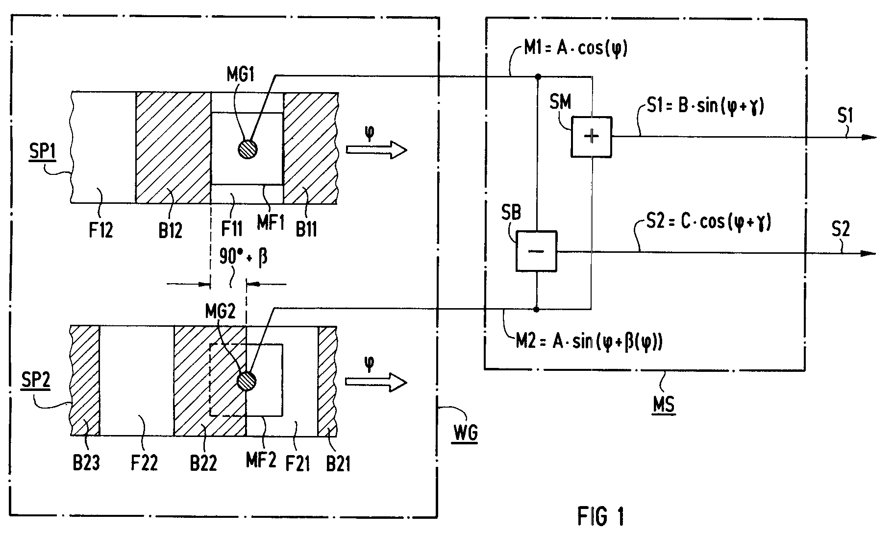
- FIG. 1 shows an example of a section WG framed in dash-dot lines by the surface of an “optical” encoder disk serving as a code carrier.
- two mutually corresponding incremental tracks SP1, SP2 from equidistant areas with alternating high and low light transmission are shown by way of example.
- the section of track SP1 shown has the areas B11, B12 with low light transmittance ("webs") and the areas F11, F12 with high light transmittance ("slots").
- the section represented by track SP2 has the areas B21, B22, B23 with low light transmission ("webs") and the areas F21, F22 with high light transmission (“slots").
- this movement can be a linear displacement, in which case the tracks SP1, SP2 have a rectilinear shape.
- this movement can also be a rotation, so that in this case the cutouts of the tracks SP1, SP2 in FIG. 1 represent ring segments.
- each incremental track SP1 or SP2 is assigned an optical encoder MG1 or MG2, which is located in the interior of an associated measurement window MF1 or MF2.
- the measuring windows have a width which approximately corresponds to the width of the areas with high or low light transmission of the track grooves SP1, SP2.
- FIG. 1 The illustration in FIG. 1 is selected by way of example so that the encoder disk WG and with it the first incremental track SP1 just assume such a position that the area F11 with high light transmission comes to lie completely above the measurement window MF1. No part of the measurement window is therefore covered by one of the adjacent areas B11, B12 with low light transmission.
- the sensor MG1 can in this case detect a maximum amount of light through the measuring window MF1, so that the first measuring signal M1 generated by it has a maximum value in this position.
- the corresponding areas with low or high light transmittance B21, B22 or F21, F22 on track SP2 are like this arranged offset that a sensor MG2, which is in the same position as the sensor MG1, generates a second measuring signal M2 in the measuring window MF2 of the track SP2, which signal is 90 ° out of phase with the measuring signal M1.
- the representation in FIG. 1 is again chosen such that the measuring window MF2 and the measuring transducer MG2 located therein are only half irradiated over the area F21 with high light transmittance, while the other half is covered by the area B22 with low light transmittance.
- phase error angle ⁇ has the position-independent, constant value of 15 °.
- second measurement signal M1 which is subject to the error angle
- the measurement signals S1, S2 are thus ideally cosine and sinusoidal to one another, and have a constant phase shift of 90 ° to one another at each value of the running factor ⁇ , regardless of the presence and the respective position-dependent value of an error angle ⁇ ( ⁇ ).
- the correction circuit according to the invention has the advantage that without precise knowledge of a possibly existing phase error angle ⁇ ( ⁇ ) at any time and at any value of the running factor ⁇ , i.e. A pair of S1, S2 of ideal cosine and sinusoidal measurement signals is available for each angular position or linear position of the encoder. With the aid of these error-angle-free measurement signals, the actual value of the position of the encoder disk WG and associated machine elements can be continuously measured with high accuracy in known evaluation circuits, not explained here in detail.
- FIG. 3 finally shows the pair of error-free measurement signals S1, S2, which can be determined with the aid of the correction circuit according to the invention on the basis of the error-signaled measurement signal shown in FIG M1, M2 results.
- the functions are shown in FIG. 3 as a reference Acos ( ⁇ ) and A ⁇ sin ( ⁇ ) additionally shown in dashed lines for a better overview.
- This variable is shown in FIG. 3 by dash-dotted lines, for example between the zero crossing of A ⁇ sin ( ⁇ ) at 180 ° and the zero crossing of S1 at 127.5 °. Furthermore, this variable is entered between the zero crossing of Acos ( ⁇ ) at 90 ° and the zero crossing of S2 at 37.5 °.
- the value of the running factor ⁇ occurring at the moment of the zero crossing of the second measurement signal S2 is recorded by measurement.
Landscapes
- Physics & Mathematics (AREA)
- General Physics & Mathematics (AREA)
- Engineering & Computer Science (AREA)
- Signal Processing (AREA)
- Transmission And Conversion Of Sensor Element Output (AREA)
Abstract
Die erfindungsgemäße Korrekturschaltung (MS) weist einen Summierer (SM) und einen Subtrahierer (SB) auf. Beiden wird ein erstes Paar an Meßsignalen ( ![]()
![]()
![]()
![]()
![]()
![]()
![]()
![]()
![]()
![]()
Description
Die Erfindung betrifft eine Vorrichtung zum Ausgleich eines Fehlwinkels.The invention relates to a device for compensating a misalignment.
Lagegeber, insbesondere Geber zur Erfassung der aktuellen Winkellage einer Welle bzw. der aktuellen Verschiebungsposition eines Linearmaßstabes, bilden lageabhängige, d.h. winkel- bzw. wegabhängige Signale mit möglichst gleicher Amplitude und Periode. Hierbei handelt es sich meist um Meßsignale, welche möglichst ideal cosinus- und sinusförmig zueinander sein sollen und eine Phasenverschiebung von 90° zueinander aufweisen. Aus einem oder mehreren Paaren von derartigen Meßsignalen wird dann in einer Auswerteschaltung des Gebers eine die aktuelle Winkellage bzw. Linearposition des Meßobjektes kennzeichnende Größe abgeleitet. Eine derartige Auswerteschaltung ist z.B. aus der Europäischen Patentanmeldung EP 0 325 981 A1 bekannt.Position encoders, in particular encoders for detecting the current angular position of a shaft or the current displacement position of a linear scale, form position-dependent, i.e. angle or path-dependent signals with the same amplitude and period as possible. These are mostly measurement signals, which should be ideally cosine and sinusoidal to each other and have a phase shift of 90 ° to each other. A variable characterizing the current angular position or linear position of the measurement object is then derived from one or more pairs of such measurement signals in an evaluation circuit of the transmitter. Such an evaluation circuit is e.g. known from European
Der Lagegeber kann z.B. nach dem optischen Prinzip arbeiten. Er weist dabei einen rotierenden bzw. linear verschiebbaren Codeträger in Form einer transparenten bzw. reflektierenden Scheibe auf. Diese ist mit Spuren belegt, die Bereiche mit abwechselnd hoher bzw. niedriger Lichtdurchlässigkeit aufweisen. Die Bereiche können z.B. dreieckförmig, in der Breite analog veränderlich oder inkrementell, d.h. mit äquidistanten Bereichen abwechselnd hoher bzw. niedriger Lichtdurchlässigkeit bzw. Refektionsfähigkeit, ausgeführt sein. Eine Lichtquelle dient zur Be- bzw. Durchleuchtung der Geberscheibe. Bei Rotation bzw. Linearverschiebung des Codeträgers verursachen die Bereiche mit abwechselnd hoher bzw. niedriger Lichtdurchlässigkeit bzw. Reflektionsfähigkeit auf den Spuren Lichtschwankungen, welche von Sensoren erfaßt und in die oben beschriebenen Meßsignalpaare umgesetzt werden.The position encoder can work according to the optical principle, for example. It has a rotating or linearly displaceable code carrier in the form of a transparent or reflecting disc. This is covered with traces that have areas with alternating high and low light transmission. The areas can, for example, be triangular, the width can be varied analogously or incrementally, ie with equidistant areas alternating with high or low light transmittance or refectivity. A light source is used to illuminate and illuminate the encoder disc. With rotation or linear displacement of the code carrier, the areas with alternating high or low light transmission or Reflectivity on the tracks of light fluctuations, which are detected by sensors and converted into the measurement signal pairs described above.
Darüber hinaus sind auch Lagegeber bekannt, welche nach magnetischen Prinzipien arbeiten. So ist z.B. in der Deutschen Patentanmeldung mit dem Aktenzeichen P 40 30 450 ein Dreh- oder Linearpositionsgeber beschrieben. Dieser weist einen Codeträger auf, dessen Oberfläche mit mindestens einer Spur aus einer Speicherschicht belegt ist, die ein inkrementelles Muster wechselnder Magnetisierungsrichtungen aufweist. Drehungen bzw. Linearbewegungen des Codeträgers werden in diesem Fall von einem ortsfesten, magnetoresistiven Sensor erfaßt. Dabei verursachen die Magnetisierungsmuster in der Speicherschicht auf der Oberfläche des Codeträgers bei Vorbeigleiten am Sensor einen wechselnden magnetischen Fluß, welcher in mindestens ein Meßsignalpaar der oben beschriebenen Art umgesetzt wird.In addition, position encoders are known which work according to magnetic principles. For example, in the German patent application with the file number P 40 30 450 describes a rotary or linear position encoder. This has a code carrier, the surface of which is covered with at least one track from a storage layer, which has an incremental pattern of changing magnetization directions. In this case, rotations or linear movements of the code carrier are detected by a fixed, magnetoresistive sensor. The magnetization patterns in the memory layer on the surface of the code carrier cause an alternating magnetic flux when sliding past the sensor, which is converted into at least one pair of measurement signals of the type described above.
Eine weitere Art von Lagegebern weist als Codeträger ein rotierendes Zahnrad bzw. eine linearverschiebbare Zahnstange auf. Ein derartiger "Zahnradgeber" ist z.B. im Deutschen Gebrauchsmuster mit dem Aktenzeichen G 91 10 524 beschrieben. In diesem Fall wird eine durch Bewegung der Zahnrad- bzw. Zahnstangenaußenseite hervorgerufene abwechselnd hohe bzw. niedrige magnetische Kopplung von einem magnetischen Sensor erfaßt, und bei entsprechender Form der Zähne bzw. der dazwischen liegenden Nuten in mindestens ein Paar der oben genannten Meßsignale umgesetzt. Schließlich sind noch weitere Formen von rotierenden bzw. linearverschiebbaren Codeträgern denkbar, welche ebenfalls Meßsignalpaare der oben genannten Art abgeben.Another type of position encoder has a rotating gear or a linearly displaceable rack as a code carrier. Such a "gear encoder" is e.g. described in German utility model with file number G 91 10 524. In this case, an alternating high or low magnetic coupling caused by movement of the outside of the gear wheel or rack is detected by a magnetic sensor and, with a corresponding shape of the teeth or the grooves located therebetween, converted into at least one pair of the above-mentioned measurement signals. Finally, other forms of rotating or linearly displaceable code carriers are also conceivable, which also emit measurement signal pairs of the type mentioned above.
Für die Genauigkeit der Erfassung des aktuellen Wertes der Winkellage bzw. Linearposition ist es bei allen Gebern von ausschlaggebender Bedeutung, daß die Meßsignale eines jeden Paares möglichst ideal cosinus- und sinusförmig zueinander sind, d.h. eine von der aktuellen Winkellage bzw. Linearposition unabhängige konstante Phasenverschiebung von 90° zueinander aufweisen. In der Praxis gibt es jedoch eine Vielzahl von Ursachen, welche einen unerwünschten, u.U. sogar von der aktuellen Winkellage bzw. Linearposition abhängigen Fehlwinkel bzw. Phasenfehler zwischen den cosinus- und sinusförmigen Meßsignalen eines jeden Paares hervorrufen können.For the accuracy of the detection of the current value of the angular position or linear position, it is of crucial importance for all encoders that the measurement signals of each pair are ideally cosine and sinusoidal to one another are, ie have a constant phase shift of 90 ° to one another which is independent of the current angular position or linear position. In practice, however, there are a number of causes which can cause an undesirable error angle or phase error, depending on the current angular position or linear position, between the cosine and sinusoidal measurement signals of each pair.
So können z.B. unvermeidbare fertigungstechnische Toleranzen eine mechanische Schiefstellung des rotierenden bzw. linear verschiebbaren Codeträgers relativ zu den ortsfesten, die Codeträgeroberfläche abtastenden Sensoren verursachen. Codeträger und Sensoren nehmen in diesem Fall somit keine ideale und ggf. zusätzlich lageabhängig veränderliche Relativposition zueinander ein. Derartige mechanische Toleranzen zwischen Codeträger und Sensoren können einen, die gewünschte Phasenverschiebung von 90° zwischen den cosinus- und sinusförmigen Meßsignalen störenden Fehlwinkel verursachen.For example, unavoidable manufacturing tolerances cause mechanical misalignment of the rotating or linearly displaceable code carrier relative to the stationary sensors that scan the code carrier surface. In this case, code carriers and sensors therefore do not assume an ideal relative position relative to one another, which may also vary depending on the position. Such mechanical tolerances between the code carrier and sensors can cause an error angle which disturbs the desired phase shift of 90 ° between the cosine and sinusoidal measurement signals.
Eine weitere Ursache für einen Fehlwinkel können Toleranzen in den Maßen des Codeträgers selbst bzw. der aufgebrachten Spuren sein. So können z.B. bei einer optischen Geberscheibe die Bereiche mit abwechselnd hoher bzw. niedriger Lichtdurchlässigkeit bzw. Reflektionsfähigkeit auf einer Inkrementalspur nicht exakt gleich groß und äquidistant sein. Auch bei Zahnradgebern ist ein jeder Zahn mit formbedingten Toleranzen behaftet. Eine weitere Ursache von Fehlwinkeln kann in der Erwärmung des Meßsystems liegen. Auch in diesem Fall wird duch Ausdehnung einer als Codeträger dienenden optischen Geberscheibe bzw. eines Meßzahnrades bzw. einer Zahnstange die Relativposition zwischen Codeträger und ortsfesten Abtastsensoren beeinträchtigt. Abhängig vom jeweiligen mechanischen Aufbau insbesondere des Codeträgers und der Sensoreinheit im Lagegeber, und abhängig von dem zur Lageerfassung eingesetzten Meßprinzip können im Einzelfall weitere Einflüsse auftreten, welche einen exemplarbedingten und lokal veränderlichen Fehlerwinkel in der Phasenlage eines jeden Paares von cosinus- und sinusförmigen Meßsignalen verursachen.Another cause of a misalignment can be tolerances in the dimensions of the code carrier itself or the traces applied. For example, in the case of an optical encoder disc, the areas with alternating high or low light transmission or reflectivity on an incremental track cannot be exactly the same size and equidistant. Even with gear wheel encoders, each tooth is subject to shape-related tolerances. Another cause of incorrect angles can be the heating of the measuring system. In this case, too, the relative position between the code carrier and the stationary scanning sensors is adversely affected by the expansion of an optical encoder disc or a measuring gear or a toothed rack serving as a code carrier. Depending on the respective mechanical structure, in particular of the code carrier and the sensor unit in the position transmitter, and depending on the measuring principle used for position detection, the In individual cases, further influences occur which cause an exemplary and locally variable error angle in the phase position of each pair of cosine and sinusoidal measurement signals.
Der Erfindung liegt die Aufgabe zugrunde, eine Meßschaltung anzugeben, die aus einem ersten Paar von fehlerwinkelbehafteten cosinus- und sinusförmigen Meßsignalen ein zweites Paar von fehlerwinkelfreien Meßsignalen abgeleitet.The invention is based on the object of specifying a measuring circuit which derives a second pair of measuring angle-free measuring signals from a first pair of cosine and sinusoidal measuring signals with a fault angle.
Die Aufgabe wird gelöst mit der im Anspruch angegebenen Vorrichtung. Die Erfindung wird desweiteren anhand eines in den nachfolgend kurz angeführten Figuren dargestellten Ausführungsbeispieles näher beschrieben. Dabei zeigt
- FIG 1
- beispielhaft einen Ausschnitt von der Oberfläche einer optischen Geberscheibe, und die erfindungsgemäße Vorrichtung in der Darstellung als Blockschaltbild,
- FIG 2
- beispielhaft ein erstes Paar von cosinus- und sinusförmigen Meßsignalen, welches einen Phasenfehlerwinkel aufweist, und
- FIG 3
- ein am Ausgang der erfindungsgemäßen Vorrichtung von FIG 1 auftretendes, phasenfehlerwinkelfreies zweites Paar an Meßsignalen.
- FIG. 1
- an example of a section of the surface of an optical encoder disk, and the device according to the invention in the illustration as a block diagram,
- FIG 2
- for example, a first pair of cosine and sinusoidal measurement signals, which has a phase error angle, and
- FIG 3
- a occurring at the output of the device according to the invention of FIG 1, phase error angle free second pair of measurement signals.
In FIG 1 ist beispielhaft ein Ausschnitt WG von der Oberfläche einer als Codeträger dienenden "optischen" Geberscheibe strichpunktiert umrahmt dargestellt. Darin sind beispielhaft zwei zueinander korrespondierende Inkrementalspuren SP1,SP2 aus äquidistanten Bereichen mit abwechselnd hoher und niedriger Lichtdurchlässigkeit dargestellt. Dabei weist der dargestellte Ausschnitt von Spur SP1 die Bereiche B11,B12 mit niedriger Lichtdurchlässigkeit ("Stege") und die Bereiche F11,F12 mit hoher Lichtdurchlässigkeit ("Schlitze") auf. Entsprechend weist der von Spur SP2 dargestellte Ausschnitt die Bereich B21,B22,B23 mit niedriger Lichtdurchlässigkeit ("Stege") und die Bereiche F21,F22 mit hoher Lichtdurchlässigkeit ("Schlitze") auf. Ferner sei angenommen, daß sich die Geberscheibe WG und mit ihr die Inkrementalspuren SP1,SP2 in eine Richtung bewegen, die in FIG 1 jeweils durch einen mit dem Lauffaktor φ markierten Pfeil angedeutet ist. Abhängig von Größe und Form der Geberscheibe WG kann es sich bei dieser Bewegung um eine Linearverschiebung handeln, wobei in diesem Fall die Spuren SP1,SP2 eine geradlinige Form aufweisen. Andererseits kann diese Bewegung auch eine Drehung sein, so daß in diesem Fall die Ausschnitte der Spuren SP1,SP2 in FIG 1 Ringsegmente darstellen.FIG. 1 shows an example of a section WG framed in dash-dot lines by the surface of an “optical” encoder disk serving as a code carrier. In it, two mutually corresponding incremental tracks SP1, SP2 from equidistant areas with alternating high and low light transmission are shown by way of example. The section of track SP1 shown has the areas B11, B12 with low light transmittance ("webs") and the areas F11, F12 with high light transmittance ("slots"). Correspondingly, the section represented by track SP2 has the areas B21, B22, B23 with low light transmission ("webs") and the areas F21, F22 with high light transmission ("slots"). Furthermore, it is assumed that the encoder disk WG and with it the incremental tracks SP1, SP2 move in a direction which is indicated in FIG. 1 by an arrow marked with the running factor φ. Depending on the size and shape of the encoder disk WG, this movement can be a linear displacement, in which case the tracks SP1, SP2 have a rectilinear shape. On the other hand, this movement can also be a rotation, so that in this case the cutouts of the tracks SP1, SP2 in FIG. 1 represent ring segments.
Bei der Geberscheibe WG im Beispiel der FIG 1 ist jeder Inkrementalspur SP1 bzw.SP2 ein optischer Meßgeber MG1 bzw. MG2 zugeordnet, welcher sich im Inneren eines dazugehörigen Meßfensters MF1 bzw.MF2 befindet. Die Meßfenster haben dabei eine Breite, welche annäherend der Breite der Bereiche mit hoher bzw. niedriger Lichtdurchlässigkeit der Spurrillen SP1,SP2 entsprechen.In the encoder disk WG in the example in FIG. 1, each incremental track SP1 or SP2 is assigned an optical encoder MG1 or MG2, which is located in the interior of an associated measurement window MF1 or MF2. The measuring windows have a width which approximately corresponds to the width of the areas with high or low light transmission of the track grooves SP1, SP2.
Die Darstellung in FIG 1 ist beispielhaft so gewählt, daß die Geberscheibe WG und mit ihr die erste Inkrementalspur SP1 gerade eine solche Position einnimmt, daß der Bereich F11 mit hoher Lichtdurchlässigkeit vollständig oberhalb des Meßfensters MF1 zu liegen kommt. Kein Teil des Meßfensters ist somit durch einen der benachbarten Bereiche B11,B12 mit niedriger Lichtdurchlässigkeit abgedeckt. Bei Beleuchtung der Geberscheibe WG kann in diesem Fall der Meßgeber MG1 durch das Meßfenster MF1 eine maximale Lichtmenge erfassen, so daß das von ihm erzeugte erste Meßsignal M1 bei dieser Lage einen maximalen Wert aufweist.The illustration in FIG. 1 is selected by way of example so that the encoder disk WG and with it the first incremental track SP1 just assume such a position that the area F11 with high light transmission comes to lie completely above the measurement window MF1. No part of the measurement window is therefore covered by one of the adjacent areas B11, B12 with low light transmission. When the sensor disk WG is illuminated, the sensor MG1 can in this case detect a maximum amount of light through the measuring window MF1, so that the first measuring signal M1 generated by it has a maximum value in this position.
Relativ zu den Bereichen mit niedriger bzw. hoher Lichtdurchlässigkeit B11,B12 bzw. F11,F12 der Spur SP1 sind die entsprechenden Bereiche mit niedriger bzw. hoher Lichtdurchlässigkeit B21,B22 bzw. F21,F22 auf der Spur SP2 so versetzt angeordnet, daß ein im Vergleich zum Meßgeber MG1 lagegleicher Meßgeber MG2 im Meßfenster MF2 der Spur SP2 ein zweites Meßsignal M2 erzeugt, welches zum Meßsignal M1 um 90° phasenversetzt ist. Dementsprechend ist wiederum in FIG 1 die Darstellung gerade so gewählt, daß das Meßfenster MF2 und der darin befindliche Meßgeber MG2 über den Bereich F21 mit hoher Lichtdurchlässigkeit nur noch zur Hälfte bestrahlt ist, während die andere Hälfte vom Bereich B22 mit niedriger Lichtdurchlässigkeit abgedeckt ist.Relative to the areas with low or high light transmittance B11, B12 or F11, F12 of track SP1, the corresponding areas with low or high light transmittance B21, B22 or F21, F22 on track SP2 are like this arranged offset that a sensor MG2, which is in the same position as the sensor MG1, generates a second measuring signal M2 in the measuring window MF2 of the track SP2, which signal is 90 ° out of phase with the measuring signal M1. Accordingly, the representation in FIG. 1 is again chosen such that the measuring window MF2 and the measuring transducer MG2 located therein are only half irradiated over the area F21 with high light transmittance, while the other half is covered by the area B22 with low light transmittance.
Bei Bewegung der Geberscheibe WG und damit der ersten und zweiten Inkrementalspur SP1,SP2 in Richtung des Lauffaktores φ entsteht somit am Ausgang der Meßgeber MG1,MG2 ein erstes Paar an Meßsignalen ![]()
![]()
![]()
![]()
In FIG 2 ist beispielhaft ein derartiges Paar von Meßsignalen M1 und M2 dargestellt. Dabei ist beispielhaft angenommen, daß der Phasenfehlerwinkel β den lageunabhängigen, konstanten Wert von 15° aufweist. Ferner ist angenommen, daß sich das erste, cosinusförmige Meßsignal ![]()
![]()
![]()
![]()
![]()
![]()
![]()
![]()
Im rechten Bereich von FIG 1 ist die erfindungsgemäße Korrekturschaltung MS strichpunktiert umrahmt in Form eines Blockschaltbildes dargestellt. Sie besteht aus einem Summierer SM und einem Subtrahierer SB, welche bevorzugt in Form von Operationsverstärkerschaltungen aufgebaut werden können. Erfindungsgemäß werden sowohl dem Summierer SM als auch dem Subtrahierer SB das erste Meßwertpaar ![]()
![]()
![]()
![]()
Durch Summierung M1 + M2 und Subtrahierung M1 - M2 wird erfindungsgemäß ein zweites Paar an Meßsignalen
![]()
![]()
gebildet. Erfindungsgemäß zeichnen sich die Meßsignale S1, S2 derart aus, daß sie bei jedem Wert des Lauffaktors φ der trigonometrischen Funktionen eine übereinstimmende Phasenverschiebung von
![]()
relativ zu einem Bezugspunkt aufweisen. Die Meßsignale S1,S2 sind somit ideal cosinus- und sinusförmig zueinander, und weisen bei jedem Wert des Lauffaktores φ unabhängig vom Vorhandensein und dem jeweiligen, gegebenenfalls lageabhängigen Wert eines Fehlerwinkels β(φ) eine konstante Phasenverschiebung von 90° zueinander auf.By summing M1 + M2 and subtracting M1 - M2, a second pair of measurement signals is obtained according to the invention
![]()
![]()
educated. According to the invention, the measurement signals S1, S2 are characterized in such a way that they have a corresponding phase shift of each time the run factor φ of the trigonometric functions
![]()
have relative to a reference point. The measurement signals S1, S2 are thus ideally cosine and sinusoidal to one another, and have a constant phase shift of 90 ° to one another at each value of the running factor φ, regardless of the presence and the respective position-dependent value of an error angle β (φ).
Die erfindungsgemäße Korrekturschaltung weist den Vorteil auf, daß ohne genaue Kenntnis eines möglicherweise vorhandenen Phasenfehlerwinkels β(φ) zu jedem Zeitpunkt und bei jedem Wert des Lauffaktores φ, d.h. bei jeder Winkellage bzw. Linearposition des Gebers ein Paar S1,S2 von ideal cosinus- und sinusförmigen Meßsignalen zur Verfügung steht. Mit Hilfe dieser fehlerwinkelfreien Meßsignale kann in bekannten, hier nicht näher erläuterten Auswerteschaltungen der Istwert der Lageposition der Geberschreibe WG und damit verbundener Maschinenelemente ständig mit hoher Genauigkeit meßtechnisch erfaßt werden.The correction circuit according to the invention has the advantage that without precise knowledge of a possibly existing phase error angle β (φ) at any time and at any value of the running factor φ, i.e. A pair of S1, S2 of ideal cosine and sinusoidal measurement signals is available for each angular position or linear position of the encoder. With the aid of these error-angle-free measurement signals, the actual value of the position of the encoder disk WG and associated machine elements can be continuously measured with high accuracy in known evaluation circuits, not explained here in detail.
In FIG 3 ist schließlich das Paar an fehlerwinkelfreien Meßsignalen S1,S2 dargestellt, welches sich mit Hilfe der erfindungsgemäßen Korrekturschaltung unter Zugrundelegung der in FIG 2 dargestellten, fehlerwinkelbehafteten Meßsignal M1,M2 ergibt. Als Referenz sind in FIG 3 zusätzlich zur besseren übersicht die Funktionen ![]()
![]()
![]()
![]()
Bei Zugrundelegung des in den Figuren 2,3 beispielhaft angenommenen, konstanten Phasenfehlerwinkels β = 15° weist die Phasenverschiebung der beiden Meßsignale S1,S2 am Ausgang der Korrekturschaltung MS übereinstimmend den Wert ![]()
![]()
Diese Größe ist in FIG 3 durch strichpunktierte Linien z.B. zwischen dem Nulldurchgang von ![]()
![]()
![]()
![]()
Bei Vorliegen des zweiten, fehlerwinkelfreien Paares an Meßsignalen S1,S2 ist es mit weiteren, im Detail nicht dargestellten Elementen leicht möglich, die unterschiedlichen Amplituden B,C der Signale S1,S2 anzugleichen. Nach einer derartigen Maßnahme stehen ideal cosinus- und sinusförmige, phasenfehlerfreie und amplitudengleiche Meßsignale zur Verfügung, welche besonders vorteilhaft zur hochgenauen Bestimmung der aktuellen Lageposition eines Winkellagegebers bzw. eines Linearmaßstabes benutzt werden können, d.h. zur Bestimmung des jeweiligen Wertes des Lauffaktores φ.In the presence of the second pair of measurement signals S1, S2, free of error angles, it is easily possible with further elements, not shown in detail, to adjust the different amplitudes B, C of the signals S1, S2. After such a measure, ideally cosine and sinusoidal, phase error-free and amplitude-equal measurement signals are available, which can be used particularly advantageously for the highly accurate determination of the current position of an angular position encoder or a linear scale, i.e. to determine the respective value of the running factor φ.
Mit Hilfe des zweiten Paares an Meßsignalen S1,S2 ist es desweiteren vorteilhaft möglich, den Fehlerwinkel bei jedem Wert des Lauffaktors φ zu bestimmen. Um dies zu erreichen wird z.B. bei einer ersten Ausführungsform der im Moment des Nulldurchganges des zweiten Meßsignales S2 auftretende Wert des Lauffaktores φ meßtechnisch erfasst. Gemäß der Beziehung
![]()
muß der cos in diesem Punkt den Winkelwert 90° aufweisen, d.h.
![]()
With the aid of the second pair of measurement signals S1, S2, it is furthermore advantageously possible to determine the error angle for each value of the running factor φ. In order to achieve this, for example in a first embodiment, the value of the running factor φ occurring at the moment of the zero crossing of the second measurement signal S2 is recorded by measurement. According to the relationship
![]()
the cos must have an angular value of 90 ° at this point, ie
![]()
Durch Gleichungsumstellung ergibt sich schließlich für den Wert des Fehlerwinkels an dieser Stelle
![]()
![]()
Claims (1)
in einem Geber zur Erfassung der Winkellage einer Welle bzw. einer Linearposition durch Abtastung (MF1,MG1; MF2,MG2) eines drehbaren oder linear verschiebbaren Codeträgers (WG; SP1: B11,F11,B12,F12; SP2: B21,F21,B22, F22,B23) gewonnen werden, und
bei Nichtauftreten eines Fehlwinkels (β(φ)) mit gleichem Lauffaktor (φ) rein cosinus- und sinusförmig zueinander sind, mit
Summierung (M1 + M2) und Subtrahierung (M1 - M2) der Meßwerte des ersten Paares (
in an encoder for detecting the angular position of a shaft or a linear position by scanning (MF1, MG1; MF2, MG2) a rotatable or linearly displaceable code carrier (WG; SP1: B11, F11, B12, F12; SP2: B21, F21, B22 , F22, B23) and
in the absence of an error angle (β (φ)) with the same running factor (φ) are purely cosine and sinusoidal to each other, with
Summation (M1 + M2) and subtraction (M1 - M2) of the measured values of the first pair (
Applications Claiming Priority (2)
| Application Number | Priority Date | Filing Date | Title |
|---|---|---|---|
| DE4242145A DE4242145A1 (en) | 1992-12-14 | 1992-12-14 | Device for compensating an error angle between a cosine and a sinusoidal, position-dependent measurement signal in the case of an angle encoder or a linear scale |
| DE4242145 | 1992-12-14 |
Publications (2)
| Publication Number | Publication Date |
|---|---|
| EP0602479A2 true EP0602479A2 (en) | 1994-06-22 |
| EP0602479A3 EP0602479A3 (en) | 1995-09-06 |
Family
ID=6475227
Family Applications (1)
| Application Number | Title | Priority Date | Filing Date |
|---|---|---|---|
| EP93119538A Withdrawn EP0602479A3 (en) | 1992-12-14 | 1993-12-03 | Compensation device for an angle error between a cosinusoidal and a sinusoidal position dependant measurement signal in an angle or linear length sensor. |
Country Status (2)
| Country | Link |
|---|---|
| EP (1) | EP0602479A3 (en) |
| DE (1) | DE4242145A1 (en) |
Cited By (2)
| Publication number | Priority date | Publication date | Assignee | Title |
|---|---|---|---|---|
| WO2004048899A3 (en) * | 2002-11-25 | 2004-10-14 | Matsushita Electric Ind Co Ltd | Device and method of detecting rotation angle |
| EP1544579A1 (en) * | 2003-12-16 | 2005-06-22 | Alps Electric Co., Ltd. | Angle detecting sensor with a phase compensating function |
Families Citing this family (6)
| Publication number | Priority date | Publication date | Assignee | Title |
|---|---|---|---|---|
| DE19601674B4 (en) * | 1996-01-18 | 2005-08-04 | Valeo Schalter Und Sensoren Gmbh | According to Differenzmeßprinzip working steering angle sensor for motor vehicles |
| DE19720968A1 (en) * | 1997-05-17 | 1998-11-19 | Ingolf Dr Weingaertner | Angle division error determination method |
| DE10036090B4 (en) * | 2000-07-25 | 2004-01-29 | Lust Antriebstechnik Gmbh | Method for the suppression of systematic errors by incremental position sensors |
| DE10056926A1 (en) | 2000-11-20 | 2002-07-18 | Optolab Licensing Gmbh | Method and device for conditioning a periodic analog signal |
| CN103234504B (en) * | 2013-04-18 | 2017-10-13 | 上海翱翼汽车电子有限公司 | A kind of error calibration, compensation method and its computer program, computer-readable recording medium |
| JP6770300B2 (en) | 2015-09-29 | 2020-10-14 | 株式会社ミツトヨ | Signal processing circuit for measuring equipment |
Family Cites Families (13)
| Publication number | Priority date | Publication date | Assignee | Title |
|---|---|---|---|---|
| DE2411627A1 (en) * | 1974-03-11 | 1975-05-28 | Perthen Johannes Dr Ing | Electrical compensation of mechanical quantity - uses method of superposition of several harmonics of fundamental wave |
| DE2544039A1 (en) * | 1975-10-02 | 1977-04-14 | Bbc Brown Boveri & Cie | Inductive position measuring system or resolver - uses amplifiers and integrator to determine amount and direction of error voltage |
| US4318617A (en) * | 1979-12-14 | 1982-03-09 | Keuffel & Esser Company | DC Shift error correction for electro-optical measuring system |
| DE3201005A1 (en) * | 1982-01-15 | 1983-07-28 | Dr. Johannes Heidenhain Gmbh, 8225 Traunreut | DEVICE FOR ERROR CORRECTION IN POSITION MEASURING SYSTEMS |
| DE3202818A1 (en) * | 1982-01-29 | 1983-08-11 | Pierburg Gmbh & Co Kg, 4040 Neuss | Method and device for conditioning an air throughput signal |
| GB2137755A (en) * | 1983-04-04 | 1984-10-10 | Computer Memories Inc | Position Encoder System having Quadrature Outputs |
| DE3409891C2 (en) * | 1984-03-17 | 1986-04-17 | Kuhnke, Falko, Dr., 3300 Braunschweig | Method for interpolating spatially periodic electrical signals |
| FR2614695B1 (en) * | 1987-04-28 | 1989-06-23 | Commissariat Energie Atomique | METHOD FOR THE DIGITIZATION AND LINEARIZATION OF A SENSOR WITH QUASI-SINUSOIDAL PERIODIC CHARACTERISTICS AND CORRESPONDING DEVICE |
| DE3901546A1 (en) * | 1987-08-07 | 1990-08-02 | Heidenhain Gmbh Dr Johannes | Position measuring device having a plurality of scanning points |
| US5043608A (en) * | 1989-08-24 | 1991-08-27 | Tektronix, Inc. | Avalanche photodiode non-linearity cancellation |
| DE4141000B4 (en) * | 1990-12-13 | 2010-11-25 | Papst Licensing Gmbh & Co. Kg | Arrangements and methods for measuring angles of rotation |
| DE9103653U1 (en) * | 1991-03-25 | 1991-06-27 | Siemens AG, 8000 München | Digital guide |
| CH683641A5 (en) * | 1991-10-01 | 1994-04-15 | Baumer Electric Ag | Converting measurement signal of absolute position measuring pick=up - Comparing measurement signal of each cycle at interface with incremental sum produced in process |
-
1992
- 1992-12-14 DE DE4242145A patent/DE4242145A1/en not_active Withdrawn
-
1993
- 1993-12-03 EP EP93119538A patent/EP0602479A3/en not_active Withdrawn
Cited By (3)
| Publication number | Priority date | Publication date | Assignee | Title |
|---|---|---|---|---|
| WO2004048899A3 (en) * | 2002-11-25 | 2004-10-14 | Matsushita Electric Ind Co Ltd | Device and method of detecting rotation angle |
| US7040025B2 (en) | 2002-11-25 | 2006-05-09 | Matsushita Electric Industrial Co., Ltd. | Device and method of detecting rotation angle |
| EP1544579A1 (en) * | 2003-12-16 | 2005-06-22 | Alps Electric Co., Ltd. | Angle detecting sensor with a phase compensating function |
Also Published As
| Publication number | Publication date |
|---|---|
| EP0602479A3 (en) | 1995-09-06 |
| DE4242145A1 (en) | 1994-06-16 |
Similar Documents
| Publication | Publication Date | Title |
|---|---|---|
| DE3239108C2 (en) | ||
| EP0914590B1 (en) | Device for determining the position of rotating shafts | |
| EP1329696B1 (en) | Absolute position detector with scale | |
| DE69930341T2 (en) | Encoder for the supply of incremental and absolute position values | |
| EP1983308B1 (en) | Position measuring device | |
| DE3325803C2 (en) | Incremental photoelectric measuring device | |
| EP0313999B1 (en) | Arrangement for measuring torque of a rotating shaft | |
| DE19962278A1 (en) | Position measuring device | |
| DE3913983A1 (en) | DEVICE FOR DETECTING SHIFTING | |
| EP1324050A2 (en) | Assembly for the detection of movement of an encoder | |
| EP1195579B1 (en) | Method for determining the absolute position | |
| AT410485B (en) | POSITION MEASURING DEVICE | |
| EP1557646A1 (en) | Rotary encoder and method for scanning the code disk of a rotary encoder | |
| EP0602479A2 (en) | Compensation device for an angle error between a cosinusoidal and a sinusoidal position dependant measurement signal in an angle or linear length sensor | |
| DE2159002C3 (en) | Device for detecting relative changes in position in a predetermined target ratio of moving parts | |
| EP0303008B1 (en) | Incremental length or angle measuring device | |
| DE4115244C2 (en) | Angle sensor for determining the rotational position of a steering shaft of a motor vehicle | |
| DE3619408C2 (en) | ||
| DE4443898A1 (en) | Relative position of two objects measurement appts. | |
| DE3510651A1 (en) | INCREMENTAL GUIDE | |
| EP0341412A1 (en) | Position coded angle sensor | |
| DE69006152T2 (en) | Coding disk. | |
| EP0714171B1 (en) | Device and method for determining the position of a body | |
| DE9217004U1 (en) | Device for compensating an angle error between a cosine and a sinusoidal, position-dependent measuring signal in an angle encoder or a linear scale | |
| EP0526730A1 (en) | Linear or angular position measuring device |
Legal Events
| Date | Code | Title | Description |
|---|---|---|---|
| PUAI | Public reference made under article 153(3) epc to a published international application that has entered the european phase |
Free format text: ORIGINAL CODE: 0009012 |
|
| AK | Designated contracting states |
Kind code of ref document: A2 Designated state(s): AT BE CH DE ES FR GB GR IT LI NL SE |
|
| PUAL | Search report despatched |
Free format text: ORIGINAL CODE: 0009013 |
|
| AK | Designated contracting states |
Kind code of ref document: A3 Designated state(s): AT BE CH DE ES FR GB GR IT LI NL SE |
|
| 17P | Request for examination filed |
Effective date: 19960104 |
|
| 17Q | First examination report despatched |
Effective date: 19960704 |
|
| STAA | Information on the status of an ep patent application or granted ep patent |
Free format text: STATUS: THE APPLICATION IS DEEMED TO BE WITHDRAWN |
|
| 18D | Application deemed to be withdrawn |
Effective date: 19970115 |