EP0602359A2 - Architektur für parallelle Rechnersysteme - Google Patents
Architektur für parallelle Rechnersysteme Download PDFInfo
- Publication number
- EP0602359A2 EP0602359A2 EP93117485A EP93117485A EP0602359A2 EP 0602359 A2 EP0602359 A2 EP 0602359A2 EP 93117485 A EP93117485 A EP 93117485A EP 93117485 A EP93117485 A EP 93117485A EP 0602359 A2 EP0602359 A2 EP 0602359A2
- Authority
- EP
- European Patent Office
- Prior art keywords
- thread
- processors
- computer program
- token
- tdq
- Prior art date
- Legal status (The legal status is an assumption and is not a legal conclusion. Google has not performed a legal analysis and makes no representation as to the accuracy of the status listed.)
- Withdrawn
Links
Images


Classifications
-
- G—PHYSICS
- G06—COMPUTING; CALCULATING OR COUNTING
- G06F—ELECTRIC DIGITAL DATA PROCESSING
- G06F9/00—Arrangements for program control, e.g. control units
- G06F9/06—Arrangements for program control, e.g. control units using stored programs, i.e. using an internal store of processing equipment to receive or retain programs
- G06F9/46—Multiprogramming arrangements
- G06F9/48—Program initiating; Program switching, e.g. by interrupt
- G06F9/4806—Task transfer initiation or dispatching
- G06F9/4843—Task transfer initiation or dispatching by program, e.g. task dispatcher, supervisor, operating system
Definitions
- the present invention generally relates to efficient parallelization of programs in parallel computer systems and, more particularly, to a unique object-storage encapsulation of queuing, communication, and schedule/dispatch systems which provide efficient problem program parallelism.
- the invention provides architectural enhancements to existing operating system tasking structures that support "multi-tasking" or "multi-programming" in a parallel computer environment.
- COHERENCE is the guarantee that there is logically only one copy of data even if there are multiple physical copies or even if it is shared by multiple processors. It includes no guarantees on atomicity, synchronization, sequentiality, etc.
- CONCEPTUAL SEQUENCE is the view that instructions are executed one at a time, in order.
- PHYSICAL SEQUENCE is the actual execution order by a physical processor, which may include execution of instructions out of conceptual sequence.
- OBSERVED SEQUENCE is the actual order of instruction execution which is observed. This may or may not conform to the conceptual or physical sequence.
- TASK SEQUENTIALITY is the guarantee that a task (process) views itself as executing instructions and referencing memory in conceptual sequence.
- INTER-TASK SEQUENTIALITY is the guarantee that a task can view other tasks as appearing to execute instructions and access memory sequentially (in conceptual sequence). This is important when independent tasks synchronize or communicate via shared data, but it is not generally important otherwise.
- ATOMICITY (BLOCK-CONCURRENCY) is the guarantee that modifications to data appear to be completely done or not done, and never partially done.
- SYNCHRONIZATION is the guarantee that an order or point of execution can be specified among two or more tasks. It is a guarantee that inter-task sequentiality, coherence and atomicity among the synchronizing tasks can be specified at that point.
- CACHE as used herein refers to a primarily hardware managed, processor-logical storage, although software may assist.
- PRIVATE STORAGE refers to software managed, task-local storage. This includes, for example, IBM System/370 registers.
- a tightly coupled multiprocessor system is the IBM System/390 9000 series family of computers.
- the basic organization of a tightly coupled multiprocessor (MP) system comprises a plurality of processors which may be selectively connected to a plurality of independently addressable memory modules known as basic storage modules (BSMs).
- BSMs basic storage modules
- N processors and M BSMs where M is typically greater than N . Since all processors require equal access to the BSMs, there is some form of N x M switch, such as a cross-bar switch, which selectively connects a processor to an addressed BSM for storing and retrieval of data.
- the operating system holds one or more processors dedicated to parallel execution.
- processors are dedicated, the context of a thread can be largely held among multiple threads, which reduces the dispatch path. Nevertheless, this method causes other inefficiencies because the dedicated processors are at times idle when the operating systems are not in use.
- Cedar is a development of the Center for Supercomputing Research and Development at the University of Illinois at Urbana-Champaign. It is designed to consist of "clusters" of modified Aliant FX/8 processors. Each cluster consists of eight tightly coupled FX/8 processors. Multiple clusters may be coupled together with a shared global memory. S. P. Midkiff and D. A. Padua, in "Compiler Algorithms for Synchronism", IEEE Transactions on Computers , vol. C-36, no. 12, December 1987, state, "It is assumed here that each processor can be made to wait, until all pending memory accesses issued by it have been completed, by calling the routine wait for memory .”
- test and testset instructions are an enhanced form of compare and swap in S/370, while the set and wait instructions are similar to test and set . This approach requires dedication of processors and spin waiting.
- the Convex Computer Corporation approach provides up to four-way tightly coupled processors.
- CONVEX UNIX uses the unique scheduling capabilities of the hardware architecture to implement an innovative mechanism, avoiding the serial bottleneck present on most parallel systems.
- the system contains a set of global registers to allow communication between processors. Each executing process is allocated one of eight sets of communication registers. Any or all of the CPUs in the system can simultaneously reference the data in a given communication register set by simply loading the appropriate index into an index register. Instructions are provided for the loading and retrieving of data from the communication registers, the locking of individual registers, and for requesting that additional processors join in a computation.
- CONVEX systems implement the division of a program into multiple parts and the synchronization of those parts in hardware, virtually eliminating the software overhead usually associated with parallel processing. This allows CONVEX systems to execute in parallel even very short pieces of parallel code, allowing the parallelization of many more parts of a typical program. While this in itself is not a new idea, traditional parallel processing systems force CPUs to be pre-allocated to a program which wants to use them. This means that no other job may use those processors while a job is running. This is all right in an environment where only one program ever runs, but in practice few systems exist in this environment.
- CONVEX systems provide a unique mechanism for a job to acquire additional CPU resources.
- CONVEX has implemented an asynchronous mechanism which does not require CPUs to be slaved to a CPU executing parallel code.
- a CPU executing a parallel program reaches a portion of the code which can be executed in parallel, it simply posts a flag, called a fork request , in its communications register set. The processor then continues executing the program.
- Any CPUs not executing a program execute a special microcode loop called the ready state.
- the ready loop CPUs scan through all the communication registers looking for a request for help posted by a processor executing a parallelizable application. When they find one, they join in the computation, immediately increasing the rate at which an application executes.
- CONVEX calls this unique feature "Automatic Self Allocating Processors", or "ASAP". ASAP allows a single program to use all the resources of an entire system.
- CONVEX UNIX is extensively tuned to minimize overhead and reduce bottlenecks.
- the system itself is semaphored for parallel execution.
- the scheduling system is designed around the parallel processing capabilities of the hardware, allowing the hardware thread creation activities to proceed without OS intervention. In a heavily loaded environment, threads are created on a priority basis, ensuring that the programs with the highest priorities get the most CPU resources.
- the CONVEX implementation demonstrates recognition of a number of things, including
- Another resource management problem arises if the machine is not dedicated to a job. When one task of the job completes its timeslice and is swapped out, another task from another job cannot be started which tries to use the resource since other tasks from the first job may still be running on other processors. If a job is swapped out, the state of this resource would have to be saved and reloaded when the job is restarted. Additionally, there are load balancing and scheduling problems and no protection within or among jobs.
- FEX By examining the state of the key, it can be determined if it is safe to read or write the corresponding word. "A major drawback to FEX is that a word can only be in two states. If a word is read and written several times in a single loop, more than two states are needed to represent its disposition. To this end some variables will be replaced by a structure with two components. One component, DATA, will hold the value associated with the variable, and the other component, KEY, will hold the integer variable used for synchronized operations. By providing integer keys instead of single bits, many states for each data word can be represented. For our purposes it is necessary to be able to set the key to a constant, or to increment it by one.”
- Counters and queues are generic concepts and are described in many basic programming books on data structures.
- the counters and queues as used in the practice of the subject invention owe many of their features and characteristics to the counters and queues defined originally in the System/38 as part of its internal machine programming interface, which is an interface approximately equivalent to the architected S/370 machine interface, but not seen directly in the S/38 by application programmers.
- the counters and queues of the S/38 are described in the patent to Hoffman et al., supra , and in IBM publication SC21-9037.
- Multi-threading operating systems such as IBM's OS/2 version 2.0 for personal computers and Sun Microsystems' Solaris, are now available, and new multithreading operating systems, such as Microsoft's Windows NT and the Posix multithreading standards for Unix, will be released in the near future or are proposed.
- the multithreading operating systems permit real processors to be accessed without large operating system overhead in the dispatching process.
- an architecture which uses a process, termed “encapsulation”, by which queues and counters are only accessed through a special operand called “object storage”.
- object storage a process, termed "encapsulation”, by which queues and counters are only accessed through a special operand called "object storage”.
- the facility alone is in control of the object storage, and the user cannot access it directly at any time. If the user needs to access a queue, the user must request it from the system. The system will in turn provide such access by issuing the user a "token". Tokens are only valid in the context in which they were issued. This token is the only means of communication between the user and the requested queue. Hence, context switching is not required for dispatch.
- the facility By providing encapsulated communications, objects and functions, the facility allows threads to communicate without incurring system overhead.
- a thread is defined as the smallest unit or path of execution through a process that can be scheduled.
- Operating systems can signal the system through the use of object storage, and the facility can recognize when threads are authorized to access the objects to permit communications without employing the operating system dispatching process.
- real processors since real processors are not dedicated, they can execute other programs when not needed. In fact, the other programs may also employ object dispatching of threads within their context. Indeed, since the state of threads is unknown to the operating system and the object dispatcher is in charge, operating support is kept at a minimum, which in itself is an important advantage of the invention.
- the queuing system is the same as that used in IBM's S/38 computers described in the patent to Hoffman et al., supra .
- the minimum number of machine cycles can be reduced from 10,000 to approximately 100, an order of two magnitude reduction.
- the invention solves not only the problem of inefficient processor use, it also greatly improves granularity.
- the architecture of the invention provides integrity features, such as authorization, sharing and the like, consistent with the environment in which it is being used.
- integrity features such as authorization, sharing and the like
- the problem-state approach is more efficient, but it provides no integrity, or protection, from intentional or accidental misuse.
- the invention provides the efficiency of problem-state operation, yet the integrity of supervisor-state services.
- the integrity is provided in a couple of ways.
- whatever mechanisms are provided by the operating system for sharing address spaces (which may be different in different operating systems) also provides accessibility to the associated object spaces. This not only provides integrity consistent with the current operating system philosophy, but it also avoids the need for yet another integrity architecture for object spaces and corresponding hardware and software expense to support it. Such a flexible integrity protection is totally lacking in current parallel systems.
- the invention makes the implementation of compilers supporting application parallelism simpler. This is done by providing the compiler designer with machine language level constructs to create and control parallelism in the application.
- the instructions, being problem-state can be generated as inline code by the compiler, avoiding the inefficiencies of operating system calls.
- the compiler designer no longer needs to create the algorithms and data structure to establish a parallel application environment or make system calls to supervisor services which degrade performance. This system is also available to the assembler language programmer.
- FTDE Fixed Task Dispatching Element
- the object storage can be implemented in hardware by use of registers or hardware arrays. It can also be implemented purely by the use of software devices. However, the more the object storage is implemented in software, the less performance improvement will be gained. With the architecture which implements the object storage according to the invention, the computer system can be fine tuned by providing a combination of hardware and software access to create the level of performance desired.
- the invention will be disclosed in the context of architectural enhancements to IBM's S/370 computer systems to support application parallelism, and more particularly in a ESA/370 (Enterprise Systems Architecture) environment, as described, for example, in IBM Enterprise Systems Architecture/370, Principles of Operation , publication SA22-7200-0.
- the operating systems which are in current use on these computers are the Multiple Virtual Storage (MVS) and Virtual Machine (VM) operating systems (OS).
- MVS Multiple Virtual Storage
- VM Virtual Machine
- a general understanding of these operating systems may be had by reference to An Introduction to Operating Systems by Harvey M. Deitel, Addison Wesley (1984), Operating Systems by H. Lorin and H. M. Deitel, Addison Wesley (1981), and by Harold S. Stone in High-Performance Computer Architecture , Addison-Wesley (1987). It will be understood, however, that the invention is not limited to either the hardware architecture of the S/370 computer systems or the MVS or VM operating systems.
- the subject invention is characterized as a small grain facility (SGF) which provides an application program with a small set of instructions that can be used to establish and manage a parallel programming environment with an absolute minimum of software or hardware overhead. This permits the speedups derived from the running of relatively small code segments in parallel to be realized rather than being swamped by the overhead associated with running them in parallel.
- SGF small grain facility
- Supervisor state dispatching of tasks in MVS or virtual processors VM is too inefficient for fine grain (less than 1000 operations) or medium grain (less than 10,000 operations) parallelism.
- the compilers and operating systems make use of new facilities provided by the invention which provide efficient "multi-tasking" or "multi-programming" within the existing operating system tasking structures. From an operating system viewpoint, this new facility effectively looks simply like register changing and branching, not a competing and conflicting system dispatcher. This new facility is referred to as thread dispatching.
- Thread dispatching is performed by a thread dispatcher which uses a number of special objects.
- the contents of these structures are not directly addressable by the user but are "created" by the user and may then be referenced in appropriate instructions.
- the content and purpose of these structures can be understood by considering what is required to define, dispatch and synchronize parallel units of work.
- the compiler defines a parallel unit of work, it must have some way of describing where in the program execution it is to begin and its initial state (e.g., general purpose register contents).
- the Thread Dispatching Element (TDE) defined below serves this purpose.
- FIG. 1 an overall block diagram of a parallel processor system incorporating the small grain facility (SGF) 100 according to the invention.
- This parallel processor system includes both tightly coupled and loosely coupled processors to illustrate the general application of the SGF 100. More specifically, in Figure 1, to the left of the SGF 100 are a plurality of processors 1021, 1022 and 1023, which share a common storage 104. Thus, the processors to the left of the SGF 100 constitute a tightly coupled multi-processor system. To the right of SGF 100 in Figure 1 is another processor 106 having a storage 108.
- each of the processors is diagrammatically represented by two blocks designated as "I” for Instruction Unit and "E" for Execution Unit.
- SV state vector
- a similar SV register 112 is associated with processor 106.
- the SGF 100 itself is composed of an object repository 1001, a parallel execution processor (here designed as P3E) 1003, and token processors 1005 and 1007 associated respectively with processors 1021, 1022 and 1023 and with processor 106.
- the object repository 1001 contains Messages Queues, Thread Dispatching Queues (TDQs) and Counter Queues.
- the state vector (SV) register 110 holds the operating and control state of the processors 1021, 1022 and 1023. From this state, the context of the program is determined by the token processor 1005, shown in more detail in Fig.3. Similarly, the SV register 112 holds the operating and control state of processor 106 from which the context of the program is determined by the token processor 1007. It will be noted that in this diagram, a portion of the SGF 100 overlaps the storage 104 and the storage 108, as indicated by respective dotted lines 1041 and 1081. This indicates that the object repository need not be physically located in a separate storage but rather may be distributed between the storages 104 and 108.
- a user i.e., application program
- a portion of the SGF 100 overlaps the execution units of the processors 1021, 1022 and 1023 to the left and the processor 106 to the right.
- P3E 1003 need not be a separate execution unit from those of the processors 1021, 1022 and 1023 and the processor 106.
- the P3E processor is typically distributed among the several processors, either as an integral part of the processors or as a co-processor module for each of the processors.
- the dotted line overlap also indicates the logical relationship established when the token processor associates an object with a problem program during the create operation.
- FIG. 2 is a block diagram of a typical one of the processors 1021, 1022 and 1023 and processor 106.
- the processor has an Instruction Control Unit (ICU) 201, a FiXed point Unit (FXU) 203 and a Floating Point Unit (FPU) 205, all connected by an Instruction (I) Bus 207, as is typical of modern processors.
- ICU Instruction Control Unit
- FXU FiXed point Unit
- FPU Floating Point Unit
- I Instruction
- P3E Unit 209 is connected to the I Bus 207.
- the P3EU 209 may be physically part of the processor or may be a separate chip on the processor module, much like a math co-processor common to many architectures.
- the ICU 201, FXU 203, FPU 205, and P3EU 209 each communicate with a plurality of memory cards 2111 and 2112 through a Data Control Unit (DCU) 213.
- a Storage Control Unit (SCU) 215 communicates via a P-Bus 217 with the ICU 201 and FXU 203 and via an SIO Bus 219 with the DCU 213 and Input/Output (I/O) Unit 221.
- the SCU 215 at power on supplies the Initial Program Load (IPL) routine from Read Only Storage (ROS) 223 to the ICU 201.
- IPL Initial Program Load
- the SCU 215 provides address and control outputs to the memory cards 2111 and 2112 via a repository selector 225 which determines whether the storage addressed is part of program memory (e.g., user or application memory) or part of the object repository, which is partitioned from the program memory in a distributed system.
- program memory e.g., user or application memory
- object repository e.g., partitioned from the program memory in a distributed system.
- processor shown in Figure 2 is generally conventional except for the addition of the P3EU 209 and the repository selector 225, these being part of the SGF 100 shown in Figure 1.
- FIG 3 is a block diagram showing the token processor data flow for encapsulation.
- the space address output 301 from the SV register 110 in Figure 3, is used for context determination when converting the token 305 output on line 303.
- the token 305 is selected by the output on line 307 from operand register (R) 309 in I-Unit 311 into an address 313 for selecting 315 an entry 317 from the object access table 318.
- the entry 317 can be further examined 319 for usage authority by comparing the authority context of the state vector 110 with the authority defined for the object access entry 317.
- queue header 325 is used to access queues 327 (shown in Figure 1) to perform the function described by operation code (Opcode) decoded 329 in I-unit 311, shown in Figures 1 and 3.
- the object repository 1001 contains the queues for the various functions as described in more detail hereinafter. When the queue is selected, the function is performed by the P3E Unit 1003, which includes a task dispatcher as described in the Hoffman et al. patent, supra .
- object repository 1001 can be addressed in a manner consistent with processor storage, making it appear to be in a common address range as suggested by memory sections 1041 and 1081. This can also facilitate hashing algorithms noted in 315 of Figure 3.
- Figure 4 is a diagram illustrating interrelationships between TDQ, SRQ, SRC, instruction stream and base registers
- Figure 5 is a diagram illustrating control unit cycle sequence interrelationships, as described in the patent to Hoffman et al., supra .
- the execution of the send message instruction is generally shown in Figure 4.
- the send message instruction enqueues the message defined in the I-field of the send message instruction; i.e., the R2 register, to a SRQ specified by the OP 1 field in the send message instruction.
- the TDEs on the wait list of the specified SRQ are enqueued to the TDQ in priority sequence.
- LSR is the load storage register array which refers to registers such as GPRs, FPRs, ARs, etc.
- the task handling apparatus includes a task dispatcher and an intertask communication mechanism.
- the task dispatcher renders the highest priority task dispatching element (TDE) on a task dispatching queue (TDQ) active. TDEs are on the TDQ in priority sequence. There are N levels of priority. Each task has a priority key which can be changed under program control.
- the active task causes instructions to be executed whereby work is performed, or it communicates with other tasks requesting the other tasks to do some work.
- the other tasks are either in an inactive dispatchable or inactive waiting state.
- the instruction fetch cycle of the active task always first tests for the need to execute I/O event cycles or dispatch cycles.
- the status of an I/O device is obtained during I/O event cycles.
- Dispatch cycles provide for storing the status of the old task dispatching element (TDE) and for loading the CPU facilities with the status of the new TDE.
- Task status includes an instruction address, instruction length count, condition code and base registers.
- the Thread Send/Receive Counter discussed below is essentially a high function semaphore.
- the literature also discusses the use of queues for synchronization and the communication of information.
- the Thread Send/Receive Queue (SRQ) provides this function.
- TDE Thread Dispatching Element
- a TDQ is a header which may contain a queue of Thread Dispatching Elements (TDEs) which are available to be dispatched. TDEs are ordered on a TDQ in ascending priority sequence (lowest value first, highest value last) by placing them on the queue according to the value in their priority field. A TDE is enqueued last within its priority so that TDEs will be serviced first in, first out (FIFO) with any given priority. This defines priority enqueuing of a TDE.
- a TDQ is "associated" with each SRC (Thread Send/Receive Counter) and SRQ (Thread Send/Receive Queue).
- the TDQ associated with an SRC or an SRQ is the TDQ to which TDEs are moved when they become dispatchable.
- SRCs which have the Short Wait Option set and which have waiting TDEs are said to be "SRCs in short wait”. If the TDQ has associated SRCs which are in short wait, then the TDQ is said to have associated short wait SRCs. There is a special consideration of short wait SRCs by the thread dispatcher. If a program attempts to reference an invalid TDQ (using a valid instruction), a specification exception occurs.
- a TDQ may be operated upon directly by the Enqueue Thread Dispatching Element (EQTDE), Dequeue Thread Dispatching Element (DQTDE), or Dispatch Thread Dispatching Queue (DTDQ) instructions.
- EQTDE Enqueue Thread Dispatching Element
- DQTDE Dequeue Thread Dispatching Element
- DTDQ Dispatch Thread Dispatching Queue
- a TDQ may be implicitly accessed as the result of operations on Thread Send/Receive Counters or Thread Send/Receive Queues which reference the TDQ (i.e., the "associated" TDQ).
- a TDQ is represented by a queue header to which TDEs are chained.
- the format of a TDQ header may be as follows:
- TDE Thread Dispatching Element
- a TDE is used to identify an executable piece of code and the attributes (e.g., priority, register contents) associated with it. TDEs may be explicitly created using the EQTDE (Enqueue Thread Dispatching Element) instruction or implicitly as the result of a send or receive type instruction.
- a TDE is used to store or load the current state at the time of a thread switch. The TDE for a particular thread can appear on a Thread Dispatching Queue (TDQ) or can be enqueued to an SRQ (Thread Send/Receive Queue) or SRC (Thread Send/Receive Counter) wait list. If a thread is eligible for instruction execution (thread dispatching), the associated TDE appears on a TDQ. If a program attempts to reference an invalid TDE (in a DQTDE (Dequeue Thread Dispatch Element) instruction), a specification exception occurs.
- TDQ Thread Dispatching Queue
- SRQ Thread Send/Receive Queue
- the format of the TDE may be as follows:
- An SRQ is an object used to exchange information between threads and to synchronize the transfer of control between threads.
- One thread can communicate with another thread by issuing a send type instruction to an SRQ or an SRC.
- Another thread can then obtain the information from the queue or counter by issuing a receive type instruction.
- Thread synchronization is provided by using Thread Send/Receive Messages and an SRQ in the following manner. When the active thread issues a Receive Message instruction and the target SRQ either (1) has no messages or (2) has no message which satisfies the search argument for the Receive Message instruction, the thread does not proceed.
- the thread is placed in the receive wait state by saving its state in a TDE and enqueuing it onto the wait list of the target SRQ.
- the thread dispatcher is then invoked to determine the next thread to be activated from the associated TDQ of the SRQ.
- the State Flags Vector of the SRQ defines the state to be saved whenever the TDE is put into wait on the SRQ. These flag values are copies to the TDE when the state is saved so that when the TDE is dispatched, the state which must be restored is known.
- Send and receive type operations are executed explicitly as instructions by threads and also be microcode functions. If a program attempts to reference an invalid SRQ, a specification exception occurs.
- the format of the SRQ header my be as follows:
- SRM Thread Send/Receive Message
- An SRM is not a separately created and addressable object like the others defined here.
- SRMs are dynamically "created” as a result of a SENDM or EQM and are "removed” from the SRQ when the information is retrieved using a Receiver Message (RECM) or Dequeue Message (DQM) instruction.
- the message information is extracted from the specified register or registers when the message is placed on an SRQ and placed in the specified register or registers when the message is retrieved from the SRQ.
- the register number or numbers are specified in the SENDM, EQM, RECM, or DQM instructions, but the register type (e.g., General Purpose Register (GPR), Access Register (AR), Floating Point Register (FPR)) is specified when the SRQ is created. In essence, this allows for register-to-register communications between threads.
- the SRM has a priority and contains a "message", which may often be a pointer to information in addressable storage.
- the storage for SRMs can be dynamically allocated from object storage.
- the format of the SRM may be as follows:
- An SRC is a thread object used in much the same way as an SRQ except that no messages are enqueued. Instead, a Send Count (SENDC) instruction causes the count field in the SRC header to be incremented. A Receive Count (RECC) instruction may cause the count to be decremented.
- the State Flags Vector of the SRC defines the state to be saved whenever a TDE is put into wait on the SRC. These flag values are copies to the TDE when the state is saved so that when the TDE is dispatched, the state which must be restored is known. If the program attempts to reference an invalid SRC, a specification exception occurs.
- the format of the SRC may be as follows:
- the objects defined above are unique in that when they are created using the defined create instructions, they are "encapsulated” by the machine. When an object is created, the create instruction returns "an address” into the "object space” which can be used by the instructions defined below to reference the object. Objects do not “reside” in regularly addressable memory and cannot be referenced using regular instructions with references to memory.
- the address returned has the following architectural properties:
- This approach provides object integrity by preventing inappropriate access and yet, potentially, very fast access to system controlled storage. Because the user does not see the actual mechanisms used to represent the object, the implementation may be changed without affecting the user. Even synchronization among threads in loosely coupled systems may be supported with this interface if the implementation mechanisms are provided.
- the dispatching of threads is handled by a machine function known as the thread dispatcher.
- the thread dispatcher is invoked implicitly by the send/receive type instructions and explicitly by the Dispatch Thread Dispatching Queue instruction. It is the responsibility of the thread dispatcher to determine which thread should be dispatched next and to accomplish the thread switch. The status of the new thread is taken from the next thread's TDE.
- TDEs which are available to be dispatched are placed on a TDQ and are usually dequeued (i.e., the TDE storage is freed) by the thread dispatcher when they are dispatched. However, if the "Fixed" option of the TDE is on, the TDE is not removed after dispatching.
- the thread dispatcher is invoked when any of the following conditions occur:
- the top TDE on the TDQ will be dispatched.
- the TDQ may be empty. If the TDQ is empty, the following happens:
- the second situation means that the thread dispatcher has run out of work.
- the programming system should place an "empty TDQ" event TDE on the TDQ to handle this situation. It will thus be dispatched when there are no more TDEs to be dispatched.
- This TDE can be used to define whatever actions the programming system wishes, including the use of system services to place the system dispatchable unit (MVS task, VM virtual processor, etc.) into a system wait.
- This TDE may be a fixed TDE if multiple tasks will attempt to access the TDQ.
- Other events may be defined to help manage the dynamic work load. Thread dispatching can only occur among threads which are logically executing one of the threading instructions. This is unlike system dispatching and can occur at any arbitrary point in a program's execution.
- All the instructions are architected as non-interruptable, since it is an objective of the invention to provide high performance access to these objects. Although it is logically feasible to interrupt operations which are in progress and block the initiation of other operations, the preferred implementation of the invention does not do this since it might cause the queue to be inaccessible by other threads for an indeterminate period. In other words, other threads should never see an SRQ or SRC as "busy" or inaccessible; however, processors in a multi-processor system may find objects inaccessible for short period of time.
- instruction execution must architecturally give the appearance that only one processor at a time is operating on an object, or group of objects, involved in the operation (i.e., object and instruction atomicity). This does not prevent the implementation from overlapping operations on objects so long as the appearance of atomicity is maintained. Some operations may require access to more than one object (e.g., moving TDEs from an SRQ to the associated TDQ).
- the implementation must ensure the consistency of all the objects involved and also that deadlocks do not occur.
- the architecture is defined such that deadlock-free operation can be guaranteed and the implementation can use a simple locking hierarchy.
- the threading instructions are as follows:
- CRSRC Create Thread Send/Receive Counter
- SRC Thread Send/Receive Counter
- the second operand contains the address of a location in storage which defines the SRC to be created.
- the limit value of the counter is set to the value specified by the limit specification. This value is treated as an unsigned binary integer. If no SRCs are allocated, a program check exception occurs.
- the limit value of the counter is set to the value specified by the limit specification. This value is treated as an unsigned binary integer.
- the initial count value is set to zero.
- the count is treated as an unsigned binary 32 bit integer.
- the long/short wait option specification may be used by the implementation to optimize its operation. If no SRCs can be allocated, a Program Check exception occurs. Condition Code: Unchanged. Boundary Requirements: None.
- CRSRQ Create Thread Send/Receive Queue
- An SRQ is created and its token is returned in the register designated by operand 1.
- the second operand must contain the address of a location in storage which defines the SRQ to be created:
- Create Thread Dispatching Queue (CRTDQ) - This instruction creates a TDQ, and its token is returned in the register designated by the first operand.
- the second operand contains the address of a location in storage which defines the TDQ to be created.
- a TDQ is created and its token is returned in the register designated by operand 1.
- the second operand must contain the address of a location in storage which defines the TDQ to be created: BYTEs BITs Description 0-1 Descriptor 0-3 Version (only '0001'B allowed) 4-15 unused
- Dequeue Message This instruction dequeues an SRM (Thread Send/Receive Message) from the designated SRQ (Thread Send/Receive Queue).
- SRM Short Send/Receive Message
- SRQ Thread Send/Receive Queue
- the SRMs on the SRQ designated by the token in R2 are searched sequentially, starting with the first SRM.
- the search is controlled by the Priority designated by bits 24-31 of R4.
- the first SRM satisfying the Search type, designated by I3, is dequeued.
- the message is placed in the register designated by R1 and the actual priority of the message is placed in bits 24-31 of R4.
- the type of register (GPR, FPR, etc.) designated by R1 is determined from the Message Type of the SRQ.
- the Search_Type is the logical inclusive OR of the designated bits. For a Search Type of binary 000x, no priority will satisfy the search type, therefore, this combination is invalid. A specification exception occurs.
- a Search_Type of binary 111x the first message is dequeued. If no message satisfies the Search_Type, or if the message list is empty, R 1 (the message) and R4 (the priority of the message) are not altered. No thread dispatching is involved in a DQM.
- Dequeue Thread Dispatching Element (DQTDE) - This instruction dequeues the designated TDE. Upon dequeue, the TDE is no longer a valid TDE.
- DQTDE Dequeue Thread Dispatching Element
- TDE No Search Priority is used.
- the TDE designated by the token in R1 is dequeued from the SRQ (Thread Send/Receive Queue) wait list, SRC (Thread Send/Receive Counter) wait list, or TDQ (Thread Dispatching Queue) designated by the token in R2.
- SRQ Thread Send/Receive Queue
- SRC Thread Send/Receive Counter
- TDQ Thread Dispatching Queue
- DSSRC Destroy Thread Send/Receive Counter
- the Thread Send/receive Counter designated by the first operand is made unavailable. If the first operand does not specify a valid SRC a specification exception occurs. Subsequent attempts to reference a destroyed SRC will result in a specification exception.
- DSSRQ Destroy Thread Send/Receive Queue
- DSTDQ Destroy Thread Dispatching Queue
- the Thread Dispatching Queue designated by the first operand is made unavailable. If the first operand does not specify a valid TDQ a specification exception occurs. Subsequent attempts to reference a destroyed TDQ will result in a specification exception.
- DTDQ Dispatch Thread Dispatching Queue
- Enqueue Message (EQM) - This instruction causes the message list of the SRQ (Thread Send/Receive Queue) to be searched, in sequence beginning with the first message.
- the Thread Send/Receive Message is enqueued to the message list of the designated Thread Send/Receive Queue with a designated priority.
- the message list of the SRQ designated by R2 is searched, in sequence, beginning with the first message.
- the priority of the message is specified by bits 24-31 of R4.
- the type of the register (GPR, FPR, etc.) designated by R1 is determined from the Message Type field of the SRQ. If there are no messages of the same priority, the new message is enqueued before the first message with a larger priority value, or last if there is none. The priority is treated as an unsigned binary value.
- Enqueue Thread Dispatching Element EQTDE
- TDE Thread Dispatching Element
- TDQ Thread Dispatching Queue
- a TDE Thread Dispatching Element defined by the TDE specification is enqueued to the specified TDQ (Thread Dispatching Queue) wait list designated by R3. Enqueuing is in priority sequence; low priority first, last within priority value. If the TDE is a fixed TDE, the address of the enqueued TDE is returned in the register specified by R1.
- the TDE_specification in the storage location designated by D2(B2), is used to control the content of the TDE:
- the format of the displayed Information is:
- TDE Thread Dispatching Element
- Thread Dispatching Element designated by R1 The contents and characteristics of the Thread Dispatching Element designated by R1 are displayed in the storage location designated by R2 and L3 (starting at the address specified in R2 up to the length specified by L3). L3 is treated as an unsigned binary value. If the number of bytes specified by L3 is inadequate, the operation simply terminates after L3 bytes have been materialized, and the condition code is set accordingly.
- the format of the displayed information is:
- Thread Dispatching Queue designated by R1 The contents and characteristics of the Thread Dispatching Queue designated by R1 are displayed in the storage location designated by R2 and L3 (starting at the address specified in R2 up to the length specified by L3).
- L3 is treated as an unsigned binary value. If the number of bytes specified by L3 is inadequate, the operation Simply terminates after L3 bytes have been materialized, and the condition code is set accordingly.
- the format of the displayed information is:
- PURGE Purge
- Receive Count This instruction causes the current value of the counter to be compared to a set limit.
- Receive Message This instruction causes a Thread Send/Receive Message to be received from a specified Thread Send/Receive Queue.
- the SRMs on the SRQ designated by R2 are searched sequentially, starting with the first SRM.
- the search is controlled by the Priority designated by bits 24-31 of R4.
- the first SRM satisfying the Search_type, designated by I3, is dequeued.
- the message is placed in the register designated by R1 and the actual priority of the message is placed in bits 24-31 of R4.
- the type of register (GPR, FPR, etc.) designated by R1 is determined from the Message Type of the SRQ.
- the meaning of the Search Type is:
- the Search_Type is the logical inclusive OR of the designated bits. For a Search Type of binary 000x, no priority will satisfy the search type, therefore, this combination is invalid. A specification exception occurs.
- a Search Type of binary 111x the first message is dequeued. If no message satisfies the Search_type, or if the message list is empty, R1 and R4 are not altered and the instruction is nullified. The current state is saved in a TDE and enqueued to the SRQ wait list and the thread dispatcher is invoked.
- Send Count This instruction causes the current value of the count field of the SRC (Thread Send/Receive Counter) to be incremented.
- R4 does not indicate register zero, the content of the register designated by R4 is compared to the "owner" value of the SRC. If the SRC is not “owned”, or if it is “owned” but the values are not the same, a specification exception is signaled and the execution of the instruction is halted. This is useful for debugging locking violations when the SRC is used as a lock.
- the current value of the count field in the SRC (Thread Send/Receive Counter) designated by R2 is incremented by the value contained in R1. If the new count value is greater than or equal to the limit value in the counter:
- Send Count and Wait This instruction causes the value of the SRC (Thread Send/Receive Counter) to be incremented by an amount contained in a register designated in the operand.
- the state of the thread issuing the instruction is saved in a TDE and enqueued onto the SRC wait queue.
- the SRC has the Short Wait Option set, and TDEs were in wait on the SRC, and no TDEs remain in wait on the SRC, then the SRC is no longer in short wait ( Engineering Note: the Short Waiters Count in the associated TDQ is decremented). The thread dispatcher is then invoked. The "owned" state and value are unaffected.
- Send Message SENDM
- SRQ Thread Send/Receive Queue
- the message list of the SRQ designated by R2 is searched, in sequence, beginning with the first message.
- the priority of the message is specified by bits 24-31 of R4.
- the type of the register (GPR, FPR, etc.) designated by R1 is determined from the Message Type field of the SRQ. If there are no messages of the same priority, the new message is enqueued before the first message with a larger priority value, or last if there is none. The priority is treated as an unsigned binary value.
- the Dispatch Control Option of the SRQ determines the TDEs (Thread Dispatching Elements) that are dequeued from the SRQ wait list and enqueued in priority sequence to the TDQ (Thread Dispatching Queue) specified in the TDE.
- the Dispatch Control Option is:
- the current state is saved in a TDE (at the same priority as the TDEs from the SRQ or SRC) and enqueued in priority order to the TDQ.
- the thread dispatcher is then invoked causing a thread switch to occur. This thread switch is referred to as a preempt wait to the thread issuing the send operation.
- Set Counter Limit Value (SETCLV) - This instruction sets the limit of the designated Thread Send/Receive Counter (SRC) to the designated value.
- the counter designated by R1 is modified as indicated by the I3 field and the value designated by R2, which is treated as an unsigned binary 32 value.
- the SRC has the Short Wait Option set, and TDEs were in wait on the SRC, and no TDEs remain in wait on the SRC, then the SRC is no longer in short wait.
- the current state is saved in a TDE (at the same priority as the TDEs from the SRQ or SRC) and enqueued in priority order to the TDQ.
- the thread dispatcher is then invoked causing a thread switch to occur. This thread switch is referred to as a preempt wait to the thread issuing the send operation. If the operation would cause an overflow or underflow the operation is initiated and an exception signaled.
- the invention implements parallel FORTRAN functions.
- FIG 6 is a block diagram of the small grain facility (SGF) emulation overview.
- the assumption for this example is that a FORTRAN application is running on an ESA/370 computer under the VM operating system wherein multiple virtual CPUs are defined for a given virtual machine.
- the FORTRAN code includes an opcode "X" which is the emulated opcode.
- the emulated opcode causes a SIE (system intrepretive execution) intercept and an exit from SIE, as described in the IBM System/370 Extended Architecture Interpretive Execution , IBM Publication SA22-7095.
- control program (CP) of the VM operating system gets control to perform the software emulation.
- the opcode is executed directly.
- the next sequential instruction (NSI) gets control, if appropriate, and the FORTRAN application processing continues.
- FIG. 7 illustrates the scenario of a fork and join using the small grain facility (SGF) according to the invention.
- the application program includes a plurality of lines of code, only some of which are represented in the figure.
- the EQTDE instruction spawns the processes; e.g., this is the "fork”.
- the main line of application code i.e., the "parent”
- the main line of code continues until it issues the Receive Count (RECC) instruction.
- the spawned processes execute until complete at which time they each, in turn, encounter the Send Count (SENDC) instruction.
- the spawned processes or threads terminate with the Dequeue Thread Dispatch Element (DQTDE) instruction.
- the count sent by the second of the spawned processes is equal to the count limit set by the Set Count Limit Value (SETCLV) instruction, at which point the parent process executes the next sequential instruction (NSI).
- SCI Set Count Limit Value
- the FORTRAN compiler For the JOIN, the FORTRAN compiler generates an SRC (Thread Send/Receive Counter) and the inline code RECC SRC_address.
- SRC Send/Receive Counter
- the compiler For the FORK (activate parallel thread) function, the compiler generates code to increment the SRC counter limit value. This keeps track of the number of parallel tasks. The compiler must also generate, as part of the thread termination code, the instruction SENDC SRC_address to signal that an offspring thread has completed. When the parent thread issues the RECC instruction, it will proceed if the count has been reached, indicating all offspring threads have terminated, or wait until the last offspring thread issues its SENDC instruction.
- SRQ Thread Send/Receive Queue
- the compiler generates an inline code RECM EQUAL,Thread_id,SRM_reg,SRQ_address.
- the thread waits for a message on its input queue from the designated thread.
- the option to wait or not can be specified on a receive message type function. If a wait is desired, the RECM instruction is used, but if waiting is not desired, the DQM (Dequeue Message) instruction is used to dequeue a message and set a return code.
- the RECM instruction is used, but if waiting is not desired, the DQM (Dequeue Message) instruction is used to dequeue a message and set a return code.
- FIG. 8 shows a barrier scenario which is similar to that of the fork and join scenario shown in Figure 7 except that each of the spawned processes cannot continue beyond the SENDCW until all reach the barrier.
- SENDCW Send Count and Wait
- a barrier has two elements; the determination of the processes making up the "group” and the number of processes in the group. It is assumed here that the FORTRAN programmer codes one or more procedures of the form
- a process group is then invoked whose procedures contain these statements.
- the user expects synchronization at each of the named barriers.
- the FORTRAN environment must do the following.
- the compiler generates a storage area for the SRC (Thread Send/Receive Counter) and inline code to access the counter:
- the "limit" value in the counters is set to the size of the group.
- the dispatching bit in the SRC is set to dispatch all the TDEs when the count is reached.
- Simple locking functions can be based on the SRC or SRM mechanisms.
- a simple locking mechanism can be implemented using an SRC wherein for a specified lock, A, the compiler creates an SRC, SRC_A, initialized with a current and limit value of one.
- event TDEs allow for easy handling of some difficult queue management problems and also provides the basis for dynamic "scheduling" of the processing of units of work.
- Fixed event TDEs allow an arbitrary number of threads to be activated upon demand. The fact that it is not necessary to know how many processes may access the TDQ can be used to advantage in dynamically "scheduling" the work activity of processes. If processes finish work which they are doing and go to a work queue for work, a fixed event TDE can be used to "recruit" available processes to help with some work. This approach makes work “scheduling" and management less static and easier to manage since much of the work management code need not worry about how many tasks are doing what.
- TDQ with "event” TDEs can be used to manage the deactivation and reactivation of system tasks as the workload fluctuates.
- a "no work event” TDE has been enqueued to the TDQ. This is a “fixed” TDE which detects the "empty” TDQ condition. Thus, it will be activated by every system task which encounters this situation.
- the "no work event” does the following:
- the wakeup TDE does the following:
- the only penalty, then, due to the race condition is the unlikely occurrence of the second situation (which has a window of one instruction).
- the benefit is no exposure to interruption while holding critical resources.
- the implementation of the small grain facility (SGF) according to the invention may be in either software or hardware or a combination of both.
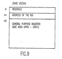
- the SGF uses a state vector (SV) having the data structure shown in Figure 9 to control the creation and dispatching of computer processes.
- the data flow shown in Figure 10 assumes a software implementation under the VM (Virtual Machine) operating system (OS) running on an ESA/370 environment in which there are N virtual CPUs associated with a given virtual machine.
- VM Virtual Machine
- OS Virtual Machine operating system
- a particular feature of the invention is the provision of an encapsulated object memory 401 which is accessed via the virtual machine 402 and not accessible directly by the user.
- S/370 architecture provides program save areas (PSAs) for each virtual CPU in the system.
- PSAs program save areas
- An SGF anchor is held within each PSA. This is a detail specific to this embodiment of the invention and is not required in the general practice of the invention.
- the encapsulated object memory 401 is accessed via the SGF anchor block for a particular virtual CPU which points to an SGF vector table (SVT) address 411 that identifies a particular SGF vector in the SGF vector table 412.
- SVT SGF vector table
- the SGF vector table includes a cell pool pointer which points to a private area 413 in memory, a prime TDQ pointer, a CPU GOWORD and lock, and a CPU TDE pointer.
- the memory 413 includes a static SGF cell pool containing SGF data structures and a bit map of the cell pool.
- Fig. 11 shows in more detail the dispatcher data structure.
- the prime TDQ pointer in SGF vector table 412 points to the TDQ 414.
- the TDQ 414 includes a descriptor (DESCR), a lock, and the address of the next TDE (TDENXT) in the queue.
- the address of the next TDE points to the TDEs 415 in the queue, each of which comprise a header identifying the TDQ and the SGF vector shown in Fig.9.
- the SGF vector table 412 also includes a pointer to the TDE for the virtual CPU (VCPU) on which it is running. This pointer points to the current TDE 416.
- VCPU virtual CPU
- Fig. 12 shows the flowchart for the thread dispatcher control flow.
- the process begins in function block 521 by getting the prime TDQ pointer from the vector table 412 ( Figure 10). Then in function block 522, the next TDE is updated in the TDQ using the compare and swap logic supported by the S/370 architecture for the specific environment taken as the example. The updated next TDE is made the current TDE in function block 523 and then, in function block 524, the state for the virtual CPU is loaded from the TDE. If there is no work, then the triggered wait TDE will be found.
- Fig. 13 shows the flowchart for the triggered wait logic. This process begins in function block 525 by getting the GOWORD lock. A test is made in decision block 526 to determine if the GOWORD lock has been obtained. If not, the re-run dispatch is invoked in function block 527 and a return is made. On the other hand, if the GOWORD lock has been obtained, zeros are stored in the GOWORD and the lock is released in function block 528. Then, in function block 529, the GOWORD is polled for a "1", and if a "1" is found in decision block 530, the dispatcher is entered in function block 531.
- the flowchart for the Dispatch Thread Dispatching Queue is shown in Figure 14.
- the process begins in function block 532 by reading the TDQ descriptor.
- a test is next made in decision block 533 to determine if a valid token has been found. If not, CC is set to "2" in function block 534 and a return is made, which will cause transfer to an address exception handling routine.
- the TDQ address is loaded in the state vector table (SVT) (412 in Figure 11) in function block 535, making this the prime TDQ.
- SVT state vector table
- the GOWORD lock is obtained in function block 536, and in function block 537, the GOWORD is set to ones and the lock released. This will trigger any waiting processors.
- a return is made to the next sequential instruction (NSI) in function block 538.
- the flowchart for the Enqueue TDE is shown in Figure 15.
- the process begins in function block 540 where a validity check is made of the token.
- decision block 541 a decision is made as to whether the token is valid. If it is not, the process fails in function block 542, but if it is valid, the TDE is enqueued in function block 543 on the addresses queue LIFO (last in, first out) stack via the compare and swap of the VM OS.
- a test is next made in decision block 544 to determine if this is the prime TDQ. If it is not, a return is made to the next sequential instruction (NSI) in function block 545.
- NAI next sequential instruction
- Fig. 16 is a flowchart illustrating the logic of the process that creates a token.
- the process begins in function block 551 with the decoding of the operation code (opcode).
- a test is made in decision block 552 to determine if the opcode is a create request. If not, encapsulated token processing is performed in function block 553, the process for which is illustrated in the flowchart of Figure 17, to which reference is made below.
- the object memory manager is called in function block 554.
- a test is made in decision block 555 by the object memory manager to determine if there is a free cell. If so, RC (return code) is set to "0"; otherwise, RC is set to "-1”.
- a free cell test is then made in decision block 556 to determine if RC is "0".
- the free cell test is required by this embodiment to detect over capacity application of the facility.
- This embodiment uses a finite object storage which has a limited capacity, hence fault indication must be provided to the application when capacity is exceeded.
- the object repository can be made to appear infinite by using virtual storage techniques.
- RC is not "0"
- a failure is detected in function block 557 and a return is made, exiting the process.
- the free cell address is placed in the next available object access table entry in function block 558.
- the object token is computed using the object table index and space address.
- CC is set to "0" in function block 560 and the created token is returned.
- encapsulated token processing is shown in the flowchart of Figure 17, to which reference is now made.
- ID the identification of the operation is queued in function block 561. This is done by means of the TDQ, SRQ and SRC.
- a register is selected for the operation in function block 562.
- the token is the address which is accessed from the register in function block 563. This address is associated with an address space ID defined by the host architecture in function block 564.
- an object access table which is accessed with the space ID, the token and the queue ID, an entry is selected in function block 565. The selected entry is tested in decision block 566 to determine if it is valid.
- a program exception is returned in function block 567, but if valid, the authority in the entry is compared to authorization per the host architecture in function block 568. A further test is made in decision block 569 to determine if the compared authorization compared properly. If not, a program exception is returned in function block 570, but if there is proper authorization, the queues are accessed in function block 571, and the function of the encapsulated operations is performed in function block 572.
Landscapes
- Engineering & Computer Science (AREA)
- Software Systems (AREA)
- Theoretical Computer Science (AREA)
- Physics & Mathematics (AREA)
- General Engineering & Computer Science (AREA)
- General Physics & Mathematics (AREA)
- Multi Processors (AREA)
Applications Claiming Priority (2)
| Application Number | Priority Date | Filing Date | Title |
|---|---|---|---|
| US07/970,729 US5485626A (en) | 1992-11-03 | 1992-11-03 | Architectural enhancements for parallel computer systems utilizing encapsulation of queuing allowing small grain processing |
| US970729 | 1992-11-03 |
Publications (2)
| Publication Number | Publication Date |
|---|---|
| EP0602359A2 true EP0602359A2 (de) | 1994-06-22 |
| EP0602359A3 EP0602359A3 (de) | 1995-02-15 |
Family
ID=25517417
Family Applications (1)
| Application Number | Title | Priority Date | Filing Date |
|---|---|---|---|
| EP93117485A Withdrawn EP0602359A3 (de) | 1992-11-03 | 1993-10-28 | Architektur für parallelle Rechnersysteme. |
Country Status (3)
| Country | Link |
|---|---|
| US (1) | US5485626A (de) |
| EP (1) | EP0602359A3 (de) |
| JP (1) | JPH06208552A (de) |
Cited By (6)
| Publication number | Priority date | Publication date | Assignee | Title |
|---|---|---|---|---|
| WO2000040006A1 (en) * | 1998-12-23 | 2000-07-06 | Powertv, Inc. | Method and apparatus for operating system kernel operations |
| EP1222529A1 (de) * | 1999-05-27 | 2002-07-17 | Computer Associates Think, Inc. | Verfahren und vorrichtung zur überwachung der kreierung und zerstörung von kind-prozessen innerhalb einer anwendungs-ausführung in einem computersystem |
| WO2005098624A1 (en) * | 2004-03-31 | 2005-10-20 | Intel Corporation | A method and system to provide user-level multithreading |
| WO2009007169A1 (en) * | 2007-07-06 | 2009-01-15 | Xmos Ltd | Synchronisation in a multithreaded processor |
| CN102023899A (zh) * | 2010-12-14 | 2011-04-20 | 中兴通讯股份有限公司 | 多线程数据同步方法及装置 |
| CN115861026A (zh) * | 2022-12-07 | 2023-03-28 | 格兰菲智能科技有限公司 | 数据处理方法、装置、计算机设备、存储介质 |
Families Citing this family (55)
| Publication number | Priority date | Publication date | Assignee | Title |
|---|---|---|---|---|
| US6035321A (en) * | 1994-06-29 | 2000-03-07 | Acis, Inc. | Method for enforcing a hierarchical invocation structure in real time asynchronous software applications |
| US6704765B1 (en) * | 1994-12-14 | 2004-03-09 | International Business Machines Corporation | System for allocating resources among agent processes |
| US5771383A (en) * | 1994-12-27 | 1998-06-23 | International Business Machines Corp. | Shared memory support method and apparatus for a microkernel data processing system |
| US5794037A (en) * | 1995-05-01 | 1998-08-11 | Intergraph Corporation | Direct access to slave processing by unprotected application using context saving and restoration |
| US5760792A (en) * | 1995-05-01 | 1998-06-02 | Intergraph Corporation | Fifo logical addresses for control and error recovery |
| JPH08328880A (ja) * | 1995-05-31 | 1996-12-13 | Mitsubishi Electric Corp | 複数のアプリケーションプログラムを同時に実行できるオペレーティングシステムにおける計算機運転管理システム |
| US5630136A (en) * | 1995-06-09 | 1997-05-13 | Sun Microsystems, Inc. | Method and apparatus for serializing access to multithreading unsafe resources |
| US5784614A (en) * | 1995-07-27 | 1998-07-21 | Ncr Corporation | Cache affinity scheduling method for multi-processor nodes in a split transaction bus architecture |
| JP3363292B2 (ja) * | 1995-10-12 | 2003-01-08 | 株式会社日立製作所 | データベース管理システム |
| US5796954A (en) * | 1995-10-13 | 1998-08-18 | Apple Computer, Inc. | Method and system for maximizing the use of threads in a file server for processing network requests |
| US6141677A (en) * | 1995-10-13 | 2000-10-31 | Apple Computer, Inc. | Method and system for assigning threads to active sessions |
| US5875329A (en) * | 1995-12-22 | 1999-02-23 | International Business Machines Corp. | Intelligent batching of distributed messages |
| US5931923A (en) * | 1996-02-16 | 1999-08-03 | Advanced Micro Devices, Inc. | System for accessing control to a peripheral device utilizing a synchronization primitive within the peripheral device |
| US5778390A (en) * | 1996-06-07 | 1998-07-07 | Electronic Data Systems Corporation | Method and systems for creating duplicating, and archiving database files |
| US6341301B1 (en) * | 1997-01-10 | 2002-01-22 | Lsi Logic Corporation | Exclusive multiple queue handling using a common processing algorithm |
| US5903770A (en) * | 1997-03-21 | 1999-05-11 | International Business Machines Corporation | Incidence graph based communications and operations method and apparatus for parallel processing architecture |
| US6108340A (en) * | 1997-03-21 | 2000-08-22 | International Business Machines Corporation | Incidence graph based communications and operations method and apparatus for parallel processing architecture |
| US5881304A (en) * | 1997-03-21 | 1999-03-09 | International Business Machines Corporation | Incidence graph based communications and operations method and apparatus for parallel processing architecture |
| US5912893A (en) * | 1997-03-21 | 1999-06-15 | International Business Machines Corporation | Incidence graph based communications and operations method and apparatus for parallel processing architecture |
| US6105112A (en) * | 1997-04-14 | 2000-08-15 | International Business Machines Corporation | Dynamic folding of cache operations for multiple coherency-size systems |
| US6247025B1 (en) * | 1997-07-17 | 2001-06-12 | International Business Machines Corporation | Locking and unlocking mechanism for controlling concurrent access to objects |
| JP3823475B2 (ja) * | 1997-09-18 | 2006-09-20 | ソニー株式会社 | データ処理方法、記録媒体及びデータ処理装置 |
| US6065019A (en) * | 1997-10-20 | 2000-05-16 | International Business Machines Corporation | Method and apparatus for allocating and freeing storage utilizing multiple tiers of storage organization |
| US6081906A (en) * | 1997-11-21 | 2000-06-27 | Fuji Xerox Co., Ltd. | Multi-thread processing with queuing and recovery |
| US6272518B1 (en) | 1998-08-17 | 2001-08-07 | International Business Machines Corporation | System and method for porting a multithreaded program to a job model |
| US6952827B1 (en) * | 1998-11-13 | 2005-10-04 | Cray Inc. | User program and operating system interface in a multithreaded environment |
| US6868541B1 (en) * | 1998-12-21 | 2005-03-15 | Microsoft Corporation | Asynchronous programming environment |
| US6636883B1 (en) * | 1999-02-22 | 2003-10-21 | International Business Machines Corporation | Mechanism for passing information between queuing and de-queuing processes |
| US6792424B1 (en) | 1999-04-23 | 2004-09-14 | International Business Machines Corporation | System and method for managing authentication and coherency in a storage area network |
| US6782537B1 (en) * | 1999-09-23 | 2004-08-24 | International Business Machines Corporation | Establishing a communicator across multiple processes in a multithreaded computing environment |
| US6651146B1 (en) * | 2000-02-24 | 2003-11-18 | International Business Machines Corporation | Method and apparatus for managing access contention to a linear list without the use of locks |
| US6931641B1 (en) * | 2000-04-04 | 2005-08-16 | International Business Machines Corporation | Controller for multiple instruction thread processors |
| US20020010848A1 (en) * | 2000-05-29 | 2002-01-24 | Shoichi Kamano | Data processing system |
| US7487152B1 (en) * | 2000-05-31 | 2009-02-03 | International Business Machines Corporation | Method for efficiently locking resources of a global data repository |
| US7140018B1 (en) * | 2000-06-20 | 2006-11-21 | International Business Machines Corporation | Method of using a distinct flow of computational control as a reusable abstract data object |
| US6615216B1 (en) | 2000-06-29 | 2003-09-02 | Microsoft Corporation | Lock free data structure maintenance |
| DE10055169A1 (de) * | 2000-08-03 | 2002-02-21 | Siemens Ag | Industrielle Steuerung auf der Basis Technologischer Objekte |
| US6882890B2 (en) * | 2000-08-03 | 2005-04-19 | Siemens Aktiengesellschaft | Industrial controller based on distributable technology objects |
| EP1217517A1 (de) * | 2000-12-22 | 2002-06-26 | Sun Microsystems, Inc. | Synchronisierung von Anrufen in einem Server-Klient System |
| US7228375B1 (en) | 2001-01-12 | 2007-06-05 | Slt Logic, Llc | System and method for efficient input/output of a computer system |
| US7240350B1 (en) * | 2002-01-07 | 2007-07-03 | Slt Logic, Llc | System and method for providing communications to processes |
| US7219345B2 (en) * | 2002-12-17 | 2007-05-15 | Hewlett-Packard Development Company, L.P. | System and method for terminating processes in a distributed computing system |
| US7386619B1 (en) * | 2003-01-06 | 2008-06-10 | Slt Logic, Llc | System and method for allocating communications to processors in a multiprocessor system |
| US7900092B2 (en) * | 2003-07-11 | 2011-03-01 | Computer Associates Think, Inc. | Kernel-level method of flagging problems in applications |
| US7873947B1 (en) * | 2005-03-17 | 2011-01-18 | Arun Lakhotia | Phylogeny generation |
| US7823158B2 (en) * | 2005-08-18 | 2010-10-26 | International Business Machines Corporation | Adaptive scheduling and management of work processing in a target context in resource contention |
| US8028295B2 (en) * | 2005-09-30 | 2011-09-27 | Intel Corporation | Apparatus, system, and method for persistent user-level thread |
| US9104508B2 (en) | 2012-01-18 | 2015-08-11 | International Business Machines Corporation | Providing by one program to another program access to a warning track facility |
| US8850450B2 (en) | 2012-01-18 | 2014-09-30 | International Business Machines Corporation | Warning track interruption facility |
| US9110878B2 (en) * | 2012-01-18 | 2015-08-18 | International Business Machines Corporation | Use of a warning track interruption facility by a program |
| JP5859472B2 (ja) * | 2013-03-26 | 2016-02-10 | 株式会社日立製作所 | プロセスの待ち行列を共有する複数のプロセッサを有する計算機、及び、プロセスディスパッチ処理方法 |
| US9195493B2 (en) | 2014-03-27 | 2015-11-24 | International Business Machines Corporation | Dispatching multiple threads in a computer |
| US9772867B2 (en) | 2014-03-27 | 2017-09-26 | International Business Machines Corporation | Control area for managing multiple threads in a computer |
| US9223574B2 (en) | 2014-03-27 | 2015-12-29 | International Business Machines Corporation | Start virtual execution instruction for dispatching multiple threads in a computer |
| US9213569B2 (en) | 2014-03-27 | 2015-12-15 | International Business Machines Corporation | Exiting multiple threads in a computer |
Citations (3)
| Publication number | Priority date | Publication date | Assignee | Title |
|---|---|---|---|---|
| US4333144A (en) * | 1980-02-05 | 1982-06-01 | The Bendix Corporation | Task communicator for multiple computer system |
| EP0205946A2 (de) * | 1985-06-17 | 1986-12-30 | International Business Machines Corporation | Flexible Datenübertragung für nachrichtenorientierte Protokolle |
| EP0362903A2 (de) * | 1985-10-15 | 1990-04-11 | Unisys Corporation | Sonderzweckprozessor zur Übernahme vieler Betriebssystemfunktionen in einem grossen Datenverarbeitungssystem |
Family Cites Families (10)
| Publication number | Priority date | Publication date | Assignee | Title |
|---|---|---|---|---|
| US4402046A (en) * | 1978-12-21 | 1983-08-30 | Intel Corporation | Interprocessor communication system |
| US4901230A (en) * | 1983-04-25 | 1990-02-13 | Cray Research, Inc. | Computer vector multiprocessing control with multiple access memory and priority conflict resolution method |
| US4636942A (en) * | 1983-04-25 | 1987-01-13 | Cray Research, Inc. | Computer vector multiprocessing control |
| JPS6079460A (ja) * | 1983-10-07 | 1985-05-07 | Nec Corp | 密結合多重演算装置における制御方式 |
| US4584639A (en) * | 1983-12-23 | 1986-04-22 | Key Logic, Inc. | Computer security system |
| US5255369A (en) * | 1984-03-10 | 1993-10-19 | Encore Computer U.S., Inc. | Multiprocessor system with reflective memory data transfer device |
| US4754398A (en) * | 1985-06-28 | 1988-06-28 | Cray Research, Inc. | System for multiprocessor communication using local and common semaphore and information registers |
| US4807111A (en) * | 1987-06-19 | 1989-02-21 | International Business Machines Corporation | Dynamic queueing method |
| US5201040A (en) * | 1987-06-22 | 1993-04-06 | Hitachi, Ltd. | Multiprocessor system having subsystems which are loosely coupled through a random access storage and which each include a tightly coupled multiprocessor |
| US5197130A (en) * | 1989-12-29 | 1993-03-23 | Supercomputer Systems Limited Partnership | Cluster architecture for a highly parallel scalar/vector multiprocessor system |
-
1992
- 1992-11-03 US US07/970,729 patent/US5485626A/en not_active Expired - Fee Related
-
1993
- 1993-10-28 EP EP93117485A patent/EP0602359A3/de not_active Withdrawn
- 1993-11-02 JP JP5274030A patent/JPH06208552A/ja active Pending
Patent Citations (3)
| Publication number | Priority date | Publication date | Assignee | Title |
|---|---|---|---|---|
| US4333144A (en) * | 1980-02-05 | 1982-06-01 | The Bendix Corporation | Task communicator for multiple computer system |
| EP0205946A2 (de) * | 1985-06-17 | 1986-12-30 | International Business Machines Corporation | Flexible Datenübertragung für nachrichtenorientierte Protokolle |
| EP0362903A2 (de) * | 1985-10-15 | 1990-04-11 | Unisys Corporation | Sonderzweckprozessor zur Übernahme vieler Betriebssystemfunktionen in einem grossen Datenverarbeitungssystem |
Non-Patent Citations (1)
| Title |
|---|
| 15TH ANNUAL INTERNATIONAL COMPUTER SOFTWARE AND APPLICATIONS CONFERENCE, COMPSAC '91 11 September 1991 , TOKYO,JP pages 398 - 405 INOHARA ET AL. 'A thread facility based on user/kernel cooperation in the XERO operating system' * |
Cited By (15)
| Publication number | Priority date | Publication date | Assignee | Title |
|---|---|---|---|---|
| WO2000040006A1 (en) * | 1998-12-23 | 2000-07-06 | Powertv, Inc. | Method and apparatus for operating system kernel operations |
| EP1222529A1 (de) * | 1999-05-27 | 2002-07-17 | Computer Associates Think, Inc. | Verfahren und vorrichtung zur überwachung der kreierung und zerstörung von kind-prozessen innerhalb einer anwendungs-ausführung in einem computersystem |
| EP1222529A4 (de) * | 1999-05-27 | 2004-06-30 | Computer Ass Think Inc | Verfahren und vorrichtung zur überwachung der kreierung und zerstörung von kind-prozessen innerhalb einer anwendungs-ausführung in einem computersystem |
| US10585667B2 (en) | 2004-03-31 | 2020-03-10 | Intel Corporation | Method and system to provide user-level multithreading |
| US9189230B2 (en) | 2004-03-31 | 2015-11-17 | Intel Corporation | Method and system to provide concurrent user-level, non-privileged shared resource thread creation and execution |
| US9442721B2 (en) | 2004-03-31 | 2016-09-13 | Intel Corporation | Method and system to provide user-level multithreading |
| WO2005098624A1 (en) * | 2004-03-31 | 2005-10-20 | Intel Corporation | A method and system to provide user-level multithreading |
| US10613858B2 (en) | 2004-03-31 | 2020-04-07 | Intel Corporation | Method and system to provide user-level multithreading |
| US10628153B2 (en) | 2004-03-31 | 2020-04-21 | Intel Corporation | Method and system to provide user-level multithreading |
| US10635438B2 (en) | 2004-03-31 | 2020-04-28 | Intel Corporation | Method and system to provide user-level multithreading |
| WO2009007169A1 (en) * | 2007-07-06 | 2009-01-15 | Xmos Ltd | Synchronisation in a multithreaded processor |
| US8966488B2 (en) | 2007-07-06 | 2015-02-24 | XMOS Ltd. | Synchronising groups of threads with dedicated hardware logic |
| CN102023899A (zh) * | 2010-12-14 | 2011-04-20 | 中兴通讯股份有限公司 | 多线程数据同步方法及装置 |
| CN115861026A (zh) * | 2022-12-07 | 2023-03-28 | 格兰菲智能科技有限公司 | 数据处理方法、装置、计算机设备、存储介质 |
| CN115861026B (zh) * | 2022-12-07 | 2023-12-01 | 格兰菲智能科技有限公司 | 数据处理方法、装置、计算机设备、存储介质 |
Also Published As
| Publication number | Publication date |
|---|---|
| JPH06208552A (ja) | 1994-07-26 |
| EP0602359A3 (de) | 1995-02-15 |
| US5485626A (en) | 1996-01-16 |
Similar Documents
| Publication | Publication Date | Title |
|---|---|---|
| US5485626A (en) | Architectural enhancements for parallel computer systems utilizing encapsulation of queuing allowing small grain processing | |
| JP2866241B2 (ja) | コンピュータシステムおよびスケジューリング方法 | |
| EP1839146B1 (de) | Mechanismus zum einteilen von threads auf os-sequestriert ohne betriebssystemintervention | |
| US7962923B2 (en) | System and method for generating a lock-free dual queue | |
| US6785887B2 (en) | Technique for using shared resources on a multi-threaded processor | |
| US6934950B1 (en) | Thread dispatcher for multi-threaded communication library | |
| US6247025B1 (en) | Locking and unlocking mechanism for controlling concurrent access to objects | |
| JP3771957B2 (ja) | プロセッサ・アーキテクチャにおける分散制御のための装置および方法 | |
| US6260057B1 (en) | Apparatus and method for high performance implementation of system calls | |
| US5274823A (en) | Interrupt handling serialization for process level programming | |
| US7844973B1 (en) | Methods and apparatus providing non-blocking access to a resource | |
| US9201689B2 (en) | Software emulation of massive hardware threading for tolerating remote memory references | |
| US20050188177A1 (en) | Method and apparatus for real-time multithreading | |
| WO2007002550A2 (en) | Primitives to enhance thread-level speculation | |
| Grossman et al. | Hardware support for fine-grained event-driven computation in Anton 2 | |
| Keckler et al. | Concurrent event handling through multithreading | |
| WO2005048009A2 (en) | Method and system for multithreaded processing using errands | |
| Armand et al. | Multi-threaded processes in CHORUS/MIX | |
| Takada et al. | A novel approach to multiprogrammed multiprocessor synchronization for real-time kernels | |
| Kissell | MIPS MT: A multithreaded RISC architecture for embedded real-time processing | |
| Michael et al. | Relative performance of preemption-safe locking and non-blocking synchronization on multiprogrammed shared memory multiprocessors | |
| US20010005880A1 (en) | Information-processing device that executes general-purpose processing and transaction processing | |
| Alfieri | An Efficient Kernel-Based Implementation of POSIX Threads. | |
| Kavi et al. | Multithreaded systems | |
| Michael et al. | Concurrent update on multiprogrammed shared memory multiprocessors |
Legal Events
| Date | Code | Title | Description |
|---|---|---|---|
| PUAI | Public reference made under article 153(3) epc to a published international application that has entered the european phase |
Free format text: ORIGINAL CODE: 0009012 |
|
| AK | Designated contracting states |
Kind code of ref document: A2 Designated state(s): DE FR GB |
|
| 17P | Request for examination filed |
Effective date: 19940927 |
|
| PUAL | Search report despatched |
Free format text: ORIGINAL CODE: 0009013 |
|
| AK | Designated contracting states |
Kind code of ref document: A3 Designated state(s): DE FR GB |
|
| STAA | Information on the status of an ep patent application or granted ep patent |
Free format text: STATUS: THE APPLICATION HAS BEEN WITHDRAWN |
|
| 18W | Application withdrawn |
Withdrawal date: 19961029 |