EP0602119B2 - Photo-acoustic leak detection and method - Google Patents
Photo-acoustic leak detection and method Download PDFInfo
- Publication number
- EP0602119B2 EP0602119B2 EP92918578A EP92918578A EP0602119B2 EP 0602119 B2 EP0602119 B2 EP 0602119B2 EP 92918578 A EP92918578 A EP 92918578A EP 92918578 A EP92918578 A EP 92918578A EP 0602119 B2 EP0602119 B2 EP 0602119B2
- Authority
- EP
- European Patent Office
- Prior art keywords
- leak
- gas
- component
- light beam
- scan
- Prior art date
- Legal status (The legal status is an assumption and is not a legal conclusion. Google has not performed a legal analysis and makes no representation as to the accuracy of the status listed.)
- Expired - Lifetime
Links
- 238000000034 method Methods 0.000 title claims abstract description 42
- 238000001514 detection method Methods 0.000 title claims abstract description 20
- 238000012360 testing method Methods 0.000 claims abstract description 29
- 239000000700 radioactive tracer Substances 0.000 claims abstract description 11
- 238000010521 absorption reaction Methods 0.000 claims description 9
- 238000012545 processing Methods 0.000 claims description 9
- 229910018503 SF6 Inorganic materials 0.000 claims description 4
- SFZCNBIFKDRMGX-UHFFFAOYSA-N sulfur hexafluoride Chemical compound FS(F)(F)(F)(F)F SFZCNBIFKDRMGX-UHFFFAOYSA-N 0.000 claims description 2
- 229960000909 sulfur hexafluoride Drugs 0.000 claims description 2
- 239000007789 gas Substances 0.000 description 38
- QGZKDVFQNNGYKY-UHFFFAOYSA-N Ammonia Chemical compound N QGZKDVFQNNGYKY-UHFFFAOYSA-N 0.000 description 11
- 229910021529 ammonia Inorganic materials 0.000 description 5
- 238000007654 immersion Methods 0.000 description 5
- 239000007788 liquid Substances 0.000 description 5
- 239000003973 paint Substances 0.000 description 5
- 239000001307 helium Substances 0.000 description 4
- 229910052734 helium Inorganic materials 0.000 description 4
- SWQJXJOGLNCZEY-UHFFFAOYSA-N helium atom Chemical compound [He] SWQJXJOGLNCZEY-UHFFFAOYSA-N 0.000 description 4
- 238000004519 manufacturing process Methods 0.000 description 4
- 230000000903 blocking effect Effects 0.000 description 3
- 238000003384 imaging method Methods 0.000 description 3
- 230000002411 adverse Effects 0.000 description 2
- 238000010586 diagram Methods 0.000 description 2
- 238000002845 discoloration Methods 0.000 description 2
- WRQGPGZATPOHHX-UHFFFAOYSA-N ethyl 2-oxohexanoate Chemical compound CCCCC(=O)C(=O)OCC WRQGPGZATPOHHX-UHFFFAOYSA-N 0.000 description 2
- 238000002347 injection Methods 0.000 description 2
- 239000007924 injection Substances 0.000 description 2
- VNWKTOKETHGBQD-UHFFFAOYSA-N methane Chemical compound C VNWKTOKETHGBQD-UHFFFAOYSA-N 0.000 description 2
- 238000012986 modification Methods 0.000 description 2
- 230000004048 modification Effects 0.000 description 2
- 238000012544 monitoring process Methods 0.000 description 2
- 238000010895 photoacoustic effect Methods 0.000 description 2
- 239000000344 soap Substances 0.000 description 2
- XLYOFNOQVPJJNP-UHFFFAOYSA-N water Substances O XLYOFNOQVPJJNP-UHFFFAOYSA-N 0.000 description 2
- 230000005534 acoustic noise Effects 0.000 description 1
- 230000003321 amplification Effects 0.000 description 1
- 238000013459 approach Methods 0.000 description 1
- 230000015572 biosynthetic process Effects 0.000 description 1
- KYKAJFCTULSVSH-UHFFFAOYSA-N chloro(fluoro)methane Chemical compound F[C]Cl KYKAJFCTULSVSH-UHFFFAOYSA-N 0.000 description 1
- 230000002596 correlated effect Effects 0.000 description 1
- 230000000875 corresponding effect Effects 0.000 description 1
- 238000001035 drying Methods 0.000 description 1
- 239000000835 fiber Substances 0.000 description 1
- 238000001914 filtration Methods 0.000 description 1
- 239000000446 fuel Substances 0.000 description 1
- 239000002828 fuel tank Substances 0.000 description 1
- 238000004868 gas analysis Methods 0.000 description 1
- 231100001261 hazardous Toxicity 0.000 description 1
- 238000011090 industrial biotechnology method and process Methods 0.000 description 1
- 230000001678 irradiating effect Effects 0.000 description 1
- 239000000463 material Substances 0.000 description 1
- 238000005259 measurement Methods 0.000 description 1
- 239000000203 mixture Substances 0.000 description 1
- 239000003345 natural gas Substances 0.000 description 1
- 238000003199 nucleic acid amplification method Methods 0.000 description 1
- 238000010422 painting Methods 0.000 description 1
- 238000010561 standard procedure Methods 0.000 description 1
- 231100000331 toxic Toxicity 0.000 description 1
- 230000002588 toxic effect Effects 0.000 description 1
Images

Classifications
-
- G—PHYSICS
- G01—MEASURING; TESTING
- G01M—TESTING STATIC OR DYNAMIC BALANCE OF MACHINES OR STRUCTURES; TESTING OF STRUCTURES OR APPARATUS, NOT OTHERWISE PROVIDED FOR
- G01M3/00—Investigating fluid-tightness of structures
- G01M3/38—Investigating fluid-tightness of structures by using light
-
- G—PHYSICS
- G01—MEASURING; TESTING
- G01M—TESTING STATIC OR DYNAMIC BALANCE OF MACHINES OR STRUCTURES; TESTING OF STRUCTURES OR APPARATUS, NOT OTHERWISE PROVIDED FOR
- G01M3/00—Investigating fluid-tightness of structures
- G01M3/02—Investigating fluid-tightness of structures by using fluid or vacuum
- G01M3/04—Investigating fluid-tightness of structures by using fluid or vacuum by detecting the presence of fluid at the leakage point
- G01M3/24—Investigating fluid-tightness of structures by using fluid or vacuum by detecting the presence of fluid at the leakage point using infrasonic, sonic, or ultrasonic vibrations
Definitions
- the present invention relates to gas leak alarm generally, and, more specifically, the inventior is directed to an apparatus and method for leak-checking of gas or liquid-tight components on the production line or in the field.
- the pressure-hold method is essentially a yes/no leak-tight test in that it only indicates to the operator whether or not the unit has a leak - it does not tell him the leak location. Furthermore, for large components with small leaks, a lengthy time period is required The procedure is also affected by any temperature changes which may occur during the monitoring period.
- a more sensitive technique involves drawing a vacuum on the component and then completely surrounding it with helium gas.
- a detector inside the vacuum system notifies the operator if helium is present in the air being pumped from the component.
- This technique is capable of detecting leaks as small as 10 -9 standard cubic centimeters/second (scc/sec), but is very expensive to set-up and to maintain, and as with the pressure-decay technique, does not indicate the location of the leak.
- the pressurization/immersion technique consists of pressurizing the component, totally immersing it in water or some other clear liquid, and observing the point of bubble emergence. This technique works quite nicely in situations involving small components which are not adversely affected by liquid immersion. However, the technique usually requires some post-test clean-up and/or drying procedure. This technique is capable of locating leaks as small as 10 -4 scc/sec with proper lighting, use of low surface tension liquids, and if adequate viewing time is allowed. It is a very labor intensive, time consuming method which requires extreme worker concentration for long periods of time. It is a leak location technique which does not very easily lend itself to automation.
- Pressurization/soaping is another leak location technique which is generally used to locate leaks from components or larger complex systems where total immersion is not practical.
- the leaky component is pressurized with air, painted or sprayed with a thin viscous liquid (usually soap), and observed for the presence of bubbles which indicate the leak location
- a thin viscous liquid usually soap
- This technique requires that the liquid soap be placed on the leak, and observed for bubble formation before it either evaporates or flows away.
- Experienced technicians say they can locate leaks as small as 10 -3 scc/sec with this technique, making it about 10 times less sensitive than the pressurization/submersion technique.
- the component With the pressurization/ammonia-sensitive painting technique, the component is coated with a water soluble, ammonia-sensitive paint, a small amount of liquid ammonia is injected into the component, it is sealed and pressurized with air.
- the ammonia/air mixture emerging from the leak produces a discoloring of the special paint thus pin-pointing the location of the leak.
- This technique is quite expensive, involves the use of a toxic material (ammonia), and requires extensive post-test clean-up. However, it offers complete coverage of the component and is quite sensitive.
- an observer can see paint discoloration within one minute at a distance of 5 meters produced by a 10 ⁇ m diameter pinhole leak pressurized to 1.3 atmospheres. Under the same conditions, a 30 ⁇ m pinhole leak will produce a 6 mm diameter discoloration within one minute.
- These leak rates are estimated to be in the 10 -3 scc/sec range.
- the tracer gas injection/detection technique involves pressurizing the component with a tracer gas. usually helium (He) or a chlorofluorocarbon (CFC), and surveying the exterior with a sensitive sniffer-type detector.
- a tracer gas usually helium (He) or a chlorofluorocarbon (CFC)
- CFC chlorofluorocarbon
- This technique is extremely sensitive, capable of locating leaks as small as 10 -6 scc/sec if the intake of the sniffer is placed directly over the source of the leak.
- Drawbacks to the He approach are the cost of the gas and the detection system: however, this technique is relatively free of background gas false readings.
- the cost of the CFC gas and detectors is quite reasonable, but these sniffers are affected by a host of common background gases, and are currently being phased out as tracer gases due to their adverse affect on the environment. Also with this technique, location of small leaks can be masked by the presence of a large leak located nearby.
- the instant invention involves a physical process commonly known as the photo-acoustic effect, which is used in various forms as a gas detection technique.
- U. S. Pat. No. 4,516,858 to Gelbwachs describes an apparatus in which a laser beam is distributed to a number of photo-acoustic cells via fiber optic cables for the purpose of monitoring hazardous gas concentrations at multiple sites.
- U. S. Pat. No. 4,557,603 to Oehler et al. discloses an apparatus for the selective detection of a variety of gases using the photo-acoustic effect.
- a monochromator is used to vary the wavelength of the light introduced to a photo-acoustic cell containing the gas to be analyzed.
- U. S. Pat. No. 4,622,845 to Ryan, et al. discloses an apparatus using a pulsed infrared light source and an acousto-optic tuneable filter to provide illumination of a photo-acoustic cell containing a gas sample extracted from the environment.
- the gas to be detected must be introduced into a photo-acoustic cell which is then irradiated with pulsed or modulated light which is spectrally selected to be strongly absorbed by the gas within the cell.
- the purpose of all of the above mentioned inventions is for concentration measurements of the gases of interest. Futher US-A-4 457 162, which describes gas analysis device including a photoacoustic cell, does specifically mention application to leak detection in natural gas systems. No further detail is provided.
- the invention provides a process and an apparatus for the detection of leaks which may exist in supposedly gas-tight or liquid-tight components and/or systems.
- the invention is based on the photo-acoustic effect which occurs when a gas absorbs light. When the wavelength of the light coincides with an absorption line of the gas, the energy absorbed produces temperature and pressure increases in the gas. If the energy absorbed is of sufficient magnitude, a pressure, or acoustic, wave is generated which may be detected by a pressure transducer, such as a microphone.
- the invention is comprised of a continuous-wave laser beam, or other well collimated beam of light, which is scanned across the component to be leak tested. The component under test is pressurized with a gas which strongly absorbs the scanned light beam.
- the emerging gas absorbs the light as it passes through it, and produces an acoustic emission which is then detected by a microphone or similar detector.
- the resulting signal may then be used to notify the operator that a leak is present.
- the scanning of the light beam across the component under test is in a repeatable or controlled pattern, the resulting acoustic signal can be used to indicate the location of the leak on the component.
- Still another object of the invention is to provide a method and apparatus for the detection of leaks by scanning the component under test with a collimated beam of light and detecting a resulting acoustic signal.
- Fig. 1 shows the primary components, of a photo-acoustic leak location/alarm (PALLA) system of the invention.
- Fig. 2 is a diagram of a one-dimensional PALLA system of the invention.
- PALLA photo-acoustic leak location/alarm
- the invention is a method and apparatus for detecting the presence of a gas leak.
- the invention comprises a collimated light source 11 and a beam scanning mechanism 12 which irradiates the leaking component 13 and an acoustic detection system 14 to detect the acoustic waves generated by the leaking gas 15 upon absorption of the light beam 16.
- the resulting signal may be used to notify the operator that the component has a leak, or if coordinated with the light beam scanning pattern, may be used to determine the location of the leak on the component 13 under test.
- FIG. 1 A block diagram showing the major components of a PALLA system is shown in Fig. 1.
- a collimated light beam 16 such as a laser beam, is scanned across the component 13 under test by a beam scanning mechanism 12.
- the component 13 has been injected with a tracer gas 17 which strongly absorbs the wavelength of the light beam 16. If the component 13 has a leak, the leaking gas 15 will absorb the scanned light as it passes through the gas 15. The absorption of the light energy results in a momentary and local pressure disturbance within the leaking gas 15 which propagates away in all directions, generally as an acoustic emission 19.
- the frequency(s) of this acoustic emission 19 will depend on the frequency(s) of irradiation of the leaking gas 15 by the scanning light beam 16.
- This acoustic emission 19 is detected by an acoustic detection system 14 and processed by a signal processing unit 20.
- the resulting leak indication signal 21 may then be used as an alarm to notify the operator that the component 13 has a leak, and/or to aid the operator in locating the source of the leak.
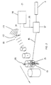
- Fig. 1 shows a two-dimensional scanning PALLA system which may be used for either leak alarm or leak location situations.
- a collimated light source 11 for example, the light beam from a CO 2 laser operating at a wavelength of 10.5514 microns, is introduced to a raster scan mechanism 12.
- the beam scanning may be accomplished by any number of standard techniques such as a two-axis scan mirror arrangement, a two-axis rotating polygon arrangement, holographic scanners, acousto-optic scanners, electro-optic scanners, pan and tilt mountings, or combinations thereof.
- the component 13 under test is positioned so as to be fully enveloped by the total 2-dimensional scan field-of-view 18, or so as to pass through the total scan field-of-view 18.
- the component 13 is pressurized with a tracer gas 17, such as sulfur hexafluoride (SF 6 ), which strongly absorbs the 10.5514 micron light. If a leak is present, the acoustic emission produced by the absorption of the laser light 16 by the SF 6 gas 15, is detected by a directional shot-gun microphone or sensitive microphone 22 and parabolic reflector 23 arrangement which is aimed at the component 13 under test.
- the signal from the microphone 22, along with scan positioning signals 26 from the beam scanning mechanism 12, are submitted to the signal processing unit 20. Careful attention must be paid so as to eliminate background acoustical noise, so use of the beam scan frequency and position signals 26 in the signal processing unit 20 is essential.
- Standard practices for extracting the acoustic emission 19 from the background acoustic noise(s), such as tuned microphones, acoustical filtering, lock-in detection and amplification, digital signal processing, or combinations thereof, are used in the signal processing unit 20 to generate the appropriate leak indication signal 21.
- Fig. 1 In its simplest application, the embodiment of Fig. 1 would be used as a leak alarm system, in which the exact location of the leak within the total scan field-of-view 18 is not required. However, due to the two-dimensional nature of the beam raster scan pattem 25, the exact location of the leak can also be determined by a number of different techniques.
- the simplest leak location technique consists of manually blocking, or shadowing, the light beam irradiation of the component by positioning a small area disc between the PALLA system and the component. As this blocking disk is passed over the component 13, it interrupts the light beam from irradiating a small area on the component 13.
- the acoustic emission 19 will still be detected. However, as the disk is positioned so as to block the light beam 16 irradiation of that region within the beam raster scan pattern 25 where the leaking gas 15 is present, the acoustic emission 19 will cease, notifying the operator that he has successfully pinpointed the leak source.
- This same leak location technique ie, local shadowing of the component 13 under test, may also be accomplished internal to the PALLA system by systematically modulating or chopping the light beam 16 at different positions of the beam raster scan pattern 25 while simultaneously noting the acoustic emission signal 19. In this manner, the horizontal and vertical position within the total scan field-of-view 18 corresponding to the reduction, or loss, of the acoustic signal indicates the location of the leak.
- a second relatively simple method of determining the location of a leak within the total scan field-of-view 18 would be to temporarily reduce the scan area, or zoom-in the field-of-view, and then manually or automatically direct this reduced scan area to various points on the component under test until the acoustic emission signal 19 is maximized.
- FIG. 2 shows a one-dimensional version of the PALLA system which may also be used as a leak alarm system.
- the collimated light beam 11 is scanned by a scanning mechanism 12 in one direction only, ie, a one-dimensional line scan pattern 29, while cross-wise motion of the component 13 under test, which has been pressurized with the tracer gas 17, provides complete coverage for leak detection purposes.
- processing of the acoustic emission signal 19 can be such as to allow for the simple alarm mode of operation, or correlated with the line scan position signal 26 and component 13 cross-wise movement to provide leak information.
Landscapes
- Physics & Mathematics (AREA)
- General Physics & Mathematics (AREA)
- Examining Or Testing Airtightness (AREA)
- Investigating Or Analyzing Materials By The Use Of Ultrasonic Waves (AREA)
Abstract
Description
- The present invention relates to gas leak alarm generally, and, more specifically, the inventior is directed to an apparatus and method for leak-checking of gas or liquid-tight components on the production line or in the field.
- The leak testing of compressors, heat exchangers, fuel tanks, fuel and hydraulic lines, pressure vessels, and window and door seals, etc, is an important manufacturing consideration in many different industries. In many cases, the gas-tight or liquid-tight integrity of these components and/or systems is usually determined by some form of a pressure-decay test. With this technique the unit under test is injected with air to some specified overpressure, and the pressure is monitored for a specified time period. If the pressure does not decay below a specified value at the end of the designated time period, the component under test is considered to be leak-free. This is a very simple, cost-effective leak checking method, and it is used for production line leak checking whenever possible. However, the pressure-hold method is essentially a yes/no leak-tight test in that it only indicates to the operator whether or not the unit has a leak - it does not tell him the leak location. Furthermore, for large components with small leaks, a lengthy time period is required The procedure is also affected by any temperature changes which may occur during the monitoring period.
- A more sensitive technique involves drawing a vacuum on the component and then completely surrounding it with helium gas. A detector inside the vacuum system notifies the operator if helium is present in the air being pumped from the component. This technique is capable of detecting leaks as small as 10-9 standard cubic centimeters/second (scc/sec), but is very expensive to set-up and to maintain, and as with the pressure-decay technique, does not indicate the location of the leak.
- Generally components which fail the pressure-decay or helium leak tests are rejected from the production process and submitted to some form of leak location testing. Pressurization/immersion, pressurization/soaping, ammonia-sensitive paint and tracer gas injection/detection, are the most common industrial techniques currently being used to pinpoint leak sources.
- The pressurization/immersion technique consists of pressurizing the component, totally immersing it in water or some other clear liquid, and observing the point of bubble emergence. This technique works quite nicely in situations involving small components which are not adversely affected by liquid immersion. However, the technique usually requires some post-test clean-up and/or drying procedure. This technique is capable of locating leaks as small as 10-4 scc/sec with proper lighting, use of low surface tension liquids, and if adequate viewing time is allowed. It is a very labor intensive, time consuming method which requires extreme worker concentration for long periods of time. It is a leak location technique which does not very easily lend itself to automation.
- Pressurization/soaping is another leak location technique which is generally used to locate leaks from components or larger complex systems where total immersion is not practical. In this technique the leaky component is pressurized with air, painted or sprayed with a thin viscous liquid (usually soap), and observed for the presence of bubbles which indicate the leak location This technique requires that the liquid soap be placed on the leak, and observed for bubble formation before it either evaporates or flows away. It is a somewhat more labor intensive technique than pressurization/immersion and always requires post-test clean-up Experienced technicians say they can locate leaks as small as 10-3 scc/sec with this technique, making it about 10 times less sensitive than the pressurization/submersion technique.
- With the pressurization/ammonia-sensitive painting technique, the component is coated with a water soluble, ammonia-sensitive paint, a small amount of liquid ammonia is injected into the component, it is sealed and pressurized with air. The ammonia/air mixture emerging from the leak produces a discoloring of the special paint thus pin-pointing the location of the leak. This technique is quite expensive, involves the use of a toxic material (ammonia), and requires extensive post-test clean-up. However, it offers complete coverage of the component and is quite sensitive. According to the paint manufacturer, an observer can see paint discoloration within one minute at a distance of 5 meters produced by a 10 µm diameter pinhole leak pressurized to 1.3 atmospheres. Under the same conditions, a 30 µm pinhole leak will produce a 6 mm diameter discoloration within one minute. These leak rates are estimated to be in the 10-3 scc/sec range.
- The tracer gas injection/detection technique involves pressurizing the component with a tracer gas. usually helium (He) or a chlorofluorocarbon (CFC), and surveying the exterior with a sensitive sniffer-type detector. This technique is extremely sensitive, capable of locating leaks as small as 10-6 scc/sec if the intake of the sniffer is placed directly over the source of the leak. Drawbacks to the He approach are the cost of the gas and the detection system: however, this technique is relatively free of background gas false readings. On the other hand, the cost of the CFC gas and detectors is quite reasonable, but these sniffers are affected by a host of common background gases, and are currently being phased out as tracer gases due to their adverse affect on the environment. Also with this technique, location of small leaks can be masked by the presence of a large leak located nearby.
- The instant invention involves a physical process commonly known as the photo-acoustic effect, which is used in various forms as a gas detection technique. For example, U. S. Pat. No. 4,516,858 to Gelbwachs describes an apparatus in which a laser beam is distributed to a number of photo-acoustic cells via fiber optic cables for the purpose of monitoring hazardous gas concentrations at multiple sites.
- U. S. Pat. No. 4,557,603 to Oehler et al., discloses an apparatus for the selective detection of a variety of gases using the photo-acoustic effect. In this case, a monochromator is used to vary the wavelength of the light introduced to a photo-acoustic cell containing the gas to be analyzed.
- U. S. Pat. No. 4,622,845 to Ryan, et al., discloses an apparatus using a pulsed infrared light source and an acousto-optic tuneable filter to provide illumination of a photo-acoustic cell containing a gas sample extracted from the environment.
- In all of the above cases, the gas to be detected must be introduced into a photo-acoustic cell which is then irradiated with pulsed or modulated light which is spectrally selected to be strongly absorbed by the gas within the cell. The purpose of all of the above mentioned inventions is for concentration measurements of the gases of interest. Futher US-A-4 457 162, which describes gas analysis device including a photoacoustic cell, does specifically mention application to leak detection in natural gas systems. No further detail is provided.
- In a article entitled "Photo-acoustic detection and ranging - a new technique for the remote detection of gases", Brassington, J. Phys. D: Appl. Phys.,
volume 15, page 219, 1982, an apparatus is described for determining the presence and range to a gas source using a pulsed laser and a microphone detector. The distance to the gas source, or range along the line-of-sight of the pulsed laser beam, is determined from the delay in receiving the acoustic pulse generated when the laser light is absorbed by the gas of interest. This technique requires a pulsed laser, and is not capable of rapidly determining the precise source of gas leaks. - The invention provides a process and an apparatus for the detection of leaks which may exist in supposedly gas-tight or liquid-tight components and/or systems. The invention is based on the photo-acoustic effect which occurs when a gas absorbs light. When the wavelength of the light coincides with an absorption line of the gas, the energy absorbed produces temperature and pressure increases in the gas. If the energy absorbed is of sufficient magnitude, a pressure, or acoustic, wave is generated which may be detected by a pressure transducer, such as a microphone. The invention is comprised of a continuous-wave laser beam, or other well collimated beam of light, which is scanned across the component to be leak tested. The component under test is pressurized with a gas which strongly absorbs the scanned light beam. If a leak occurs, the emerging gas absorbs the light as it passes through it, and produces an acoustic emission which is then detected by a microphone or similar detector. The resulting signal may then be used to notify the operator that a leak is present. Furthermore, if the scanning of the light beam across the component under test is in a repeatable or controlled pattern, the resulting acoustic signal can be used to indicate the location of the leak on the component. This invention will be a valuable addition to the Backscatter Absorption Gas Imaging system of U.S. Pat. No. 4,555,627.
- Accordingly, it is a principal object of the invention to provide a new and improved leak detection process and apparatus.
- It is another an object of this invention to provide a process that will quickly notify the operator that a component or system has a leak.
- Still another object of the invention is to provide a method and apparatus for the detection of leaks by scanning the component under test with a collimated beam of light and detecting a resulting acoustic signal.
- These and other objects of the invention will become apparent to those skilled in the art to which the invention pertains when taken in light of the annexed drawings.
- Fig. 1 shows the primary components, of a photo-acoustic leak location/alarm (PALLA) system of the invention. Fig. 2 is a diagram of a one-dimensional PALLA system of the invention.
- The invention is a method and apparatus for detecting the presence of a gas leak. The invention comprises a collimated
light source 11 and abeam scanning mechanism 12 which irradiates the leakingcomponent 13 and anacoustic detection system 14 to detect the acoustic waves generated by the leakinggas 15 upon absorption of thelight beam 16. The resulting signal may be used to notify the operator that the component has a leak, or if coordinated with the light beam scanning pattern, may be used to determine the location of the leak on thecomponent 13 under test. - A block diagram showing the major components of a PALLA system is shown in Fig. 1. A collimated
light beam 16, such as a laser beam, is scanned across thecomponent 13 under test by abeam scanning mechanism 12. Thecomponent 13 has been injected with atracer gas 17 which strongly absorbs the wavelength of thelight beam 16. If thecomponent 13 has a leak, the leakinggas 15 will absorb the scanned light as it passes through thegas 15. The absorption of the light energy results in a momentary and local pressure disturbance within the leakinggas 15 which propagates away in all directions, generally as anacoustic emission 19. The frequency(s) of thisacoustic emission 19 will depend on the frequency(s) of irradiation of the leakinggas 15 by thescanning light beam 16. Thisacoustic emission 19 is detected by anacoustic detection system 14 and processed by asignal processing unit 20. The resultingleak indication signal 21 may then be used as an alarm to notify the operator that thecomponent 13 has a leak, and/or to aid the operator in locating the source of the leak. - The embodiment of Fig. 1 shows a two-dimensional scanning PALLA system which may be used for either leak alarm or leak location situations. A collimated
light source 11, for example, the light beam from a CO2 laser operating at a wavelength of 10.5514 microns, is introduced to araster scan mechanism 12. The beam scanning may be accomplished by any number of standard techniques such as a two-axis scan mirror arrangement, a two-axis rotating polygon arrangement, holographic scanners, acousto-optic scanners, electro-optic scanners, pan and tilt mountings, or combinations thereof. Thecomponent 13 under test is positioned so as to be fully enveloped by the total 2-dimensional scan field-of-view 18, or so as to pass through the total scan field-of-view 18. Thecomponent 13 is pressurized with atracer gas 17, such as sulfur hexafluoride (SF6), which strongly absorbs the 10.5514 micron light. If a leak is present, the acoustic emission produced by the absorption of thelaser light 16 by the SF6 gas 15, is detected by a directional shot-gun microphone orsensitive microphone 22 andparabolic reflector 23 arrangement which is aimed at thecomponent 13 under test. The signal from themicrophone 22, along with scan positioning signals 26 from thebeam scanning mechanism 12, are submitted to thesignal processing unit 20. Careful attention must be paid so as to eliminate background acoustical noise, so use of the beam scan frequency and position signals 26 in thesignal processing unit 20 is essential. Standard practices for extracting theacoustic emission 19 from the background acoustic noise(s), such as tuned microphones, acoustical filtering, lock-in detection and amplification, digital signal processing, or combinations thereof, are used in thesignal processing unit 20 to generate the appropriateleak indication signal 21. - In its simplest application, the embodiment of Fig. 1 would be used as a leak alarm system, in which the exact location of the leak within the total scan field-of-
view 18 is not required. However, due to the two-dimensional nature of the beamraster scan pattem 25, the exact location of the leak can also be determined by a number of different techniques. The simplest leak location technique consists of manually blocking, or shadowing, the light beam irradiation of the component by positioning a small area disc between the PALLA system and the component. As this blocking disk is passed over thecomponent 13, it interrupts the light beam from irradiating a small area on thecomponent 13. If the blocking disk is in a region of the beamraster scan pattern 25 where no gas is present, then theacoustic emission 19 will still be detected. However, as the disk is positioned so as to block thelight beam 16 irradiation of that region within the beamraster scan pattern 25 where the leakinggas 15 is present, theacoustic emission 19 will cease, notifying the operator that he has successfully pinpointed the leak source. This same leak location technique, ie, local shadowing of thecomponent 13 under test, may also be accomplished internal to the PALLA system by systematically modulating or chopping thelight beam 16 at different positions of the beamraster scan pattern 25 while simultaneously noting theacoustic emission signal 19. In this manner, the horizontal and vertical position within the total scan field-of-view 18 corresponding to the reduction, or loss, of the acoustic signal indicates the location of the leak. - A second relatively simple method of determining the location of a leak within the total scan field-of-
view 18 would be to temporarily reduce the scan area, or zoom-in the field-of-view, and then manually or automatically direct this reduced scan area to various points on the component under test until theacoustic emission signal 19 is maximized. - Another embodiment of Fig. 2 shows a one-dimensional version of the PALLA system which may also be used as a leak alarm system. In this embodiment, the collimated
light beam 11 is scanned by ascanning mechanism 12 in one direction only, ie, a one-dimensionalline scan pattern 29, while cross-wise motion of thecomponent 13 under test, which has been pressurized with thetracer gas 17, provides complete coverage for leak detection purposes. As with the embodiment of Fig. 1, processing of theacoustic emission signal 19 can be such as to allow for the simple alarm mode of operation, or correlated with the linescan position signal 26 andcomponent 13 cross-wise movement to provide leak information. - Two embodiments of a Backscatter Absorption Gas Imaging (BAGI) System which would accomplish the two-dimensional raster scan of a laser beam across the component under test are shown in U.S. Patent No. 4,555,627 to McRae, a pint inventor of the instant invention. The synchro-scan mechanism is a modification of a conventional IR imager, e.g., the Inframetrics, Inc. Model 500L Fast Scan IR Thermal Imager, and is currently used in the Laser Imaging Systems (LIS) GasVue leak location systems.
- While the invention has been explained with respect to a preferred embodiment thereof, it is contemplated that various changes may be made in the invention without departing from the scope thereof. Changes and modifications of the specifically described embodiments can be carried out without departing from the scope of the invention and is intended to be limited only by the scope of the appended claims.
Claims (9)
- Apparatus for rapid detection of a gas leak emerging from a gas-tight or liquid-tight component (13) under test comprising:a light source (11) for providing a collimated continuous light beam (16) at a wavelength strongly absorbed by the leaking gas.beam scanning means (12) optically aligned with said light source for scanning said light beam across said component under test at a beam scan frequency in a predetermined pattern and for providing a scan positioning signal output,acoustic detection means (14) for detecting acoustic waves generated by said gas leak up-on absorption of said light beam and for producing an electrical signal proportional to the acoustic emission, andsignal processing means (20) connected to said beam scanning means (12) and said acoustic detection means (14) processing said detected acoustic waves with relation to the beam scan frequency and scan position signals for extracting the gas leak acoustic emissions from background acoustic emissions and generating a leak indication signal.
- Apparatus according to claim 1 wherein said wavelength is an absorption wavelength of sulfur hexafluoride which in use of the apparatus is injected into the component under test.
- Apparatus according to claim 1 wherein said light source comprises a laser.
- Apparatus according to claim 3 wherein said laser compnses a CO2 laser operating at a wavelength of 10.5514 microns.
- Apparatus according to claim 1 wherein said component under test is positioned so as to be irradiated by a two-dimensional, raster-type scan of said light beam.
- Apparatus according to claim 1 wherein said component under test is positioned to be scanned by said light beam in one dimension with cross-wise motion of said component providing complete coverage for leak detection.
- A method for detecting a gas leak emerging from a gas-tight or liquid-tight component under test compnsing the steps of:injecting a tracer gas into said component under test.scanning a continuous collimated light beam at a wave length strongly absorbed by the tracer gas across said component at a beam scan frequency in a predetermined pattern, and generating a scan position signal indicating the location of said light beam in a predetermined field of view.detecting acoustic emissions generated by said tracer gas upon absorption of said light beam. andprocessing said detected acoustic waves with relation to the beam scan frequency and scan position signals and providing leak indicating signals for indicating the existence of a leak.
- A method according to claim 7 wherein said predetermined pattern consists of a two-dimensional scan pattern of said light beam.
- A method according to claim 7 wherein said predetermined pattern consists of a cross-wise movement of said component and a one-dimensional scan by said light beam.
Applications Claiming Priority (3)
| Application Number | Priority Date | Filing Date | Title |
|---|---|---|---|
| US07/749,910 US5161408A (en) | 1991-08-26 | 1991-08-26 | Photo-acoustic leak detection system and method |
| PCT/US1992/006949 WO1993004352A1 (en) | 1991-08-26 | 1992-08-20 | Photo-acoustic leak detection and method |
| US749910 | 1996-11-15 |
Publications (4)
| Publication Number | Publication Date |
|---|---|
| EP0602119A1 EP0602119A1 (en) | 1994-06-22 |
| EP0602119A4 EP0602119A4 (en) | 1994-06-29 |
| EP0602119B1 EP0602119B1 (en) | 1996-06-05 |
| EP0602119B2 true EP0602119B2 (en) | 1999-04-07 |
Family
ID=25015727
Family Applications (1)
| Application Number | Title | Priority Date | Filing Date |
|---|---|---|---|
| EP92918578A Expired - Lifetime EP0602119B2 (en) | 1991-08-26 | 1992-08-20 | Photo-acoustic leak detection and method |
Country Status (7)
| Country | Link |
|---|---|
| US (1) | US5161408A (en) |
| EP (1) | EP0602119B2 (en) |
| JP (1) | JP3040474B2 (en) |
| AT (1) | ATE139029T1 (en) |
| CA (1) | CA2116345C (en) |
| DE (1) | DE69211350T3 (en) |
| WO (1) | WO1993004352A1 (en) |
Families Citing this family (50)
| Publication number | Priority date | Publication date | Assignee | Title |
|---|---|---|---|---|
| EP0552044B1 (en) * | 1992-01-16 | 1996-10-09 | Kabushiki Kaisha Toshiba | Method and apparatus for detecting the position of an abnormal site of a buried pipe |
| US5576480A (en) * | 1992-11-06 | 1996-11-19 | Pall Corporation | System and method for testing the integrity of porous elements |
| US5417113A (en) * | 1993-08-18 | 1995-05-23 | The United States Of America As Represented By The Administrator Of The National Aeronautics And Space Administration | Leak detection utilizing analog binaural (VLSI) techniques |
| EP0640822B1 (en) * | 1993-08-30 | 1998-04-22 | Millipore Investment Holdings Limited | Integrity test for porous structures using acoustic emission |
| DE4415852A1 (en) * | 1994-05-05 | 1995-11-09 | Gerhart Schroff | Holder, housing, receptacle imperviousness testing method |
| AU4391096A (en) * | 1995-01-14 | 1996-07-31 | Gerhart Schroff | Method and device for checking tightness |
| JPH09304281A (en) * | 1996-05-09 | 1997-11-28 | Tokyo Electric Power Co Inc:The | Oil detector |
| US5854422A (en) * | 1996-07-10 | 1998-12-29 | K-Line Industries, Inc. | Ultrasonic detector |
| US5780724A (en) * | 1997-03-27 | 1998-07-14 | United Technologies Corp | Photo-acoustic leak detector with improved signal-to-noise response |
| US5834632A (en) * | 1997-03-27 | 1998-11-10 | United Technologies Corporation | Photo-acoustic leak detector with multiple beams |
| US5979239A (en) * | 1997-04-28 | 1999-11-09 | The United States Of America As Represented By The Administrator Of The National Aeronautics And Space Administration | Ultrasonic imaging system |
| US6157033A (en) * | 1998-05-18 | 2000-12-05 | Power Distribution Services, Inc. | Leak detection system |
| US6154307A (en) | 1998-09-18 | 2000-11-28 | United Technologies Corporation | Method and apparatus to diffract multiple beams |
| US6089076A (en) * | 1998-09-18 | 2000-07-18 | United Technologies Corporation | System to control the power of a beam |
| US6227036B1 (en) | 1998-10-28 | 2001-05-08 | The Regents Of The University Of Michigan | Multiple microphone photoacoustic leak detection and localization system and method |
| FR2786566B1 (en) * | 1998-11-26 | 2000-12-29 | Cit Alcatel | METHOD AND DEVICE FOR DETECTING LEAKS ON AUTOMOTIVE EXCHANGERS |
| GB0015691D0 (en) * | 2000-06-28 | 2000-08-16 | Bae Systems Plc | Detection of fuel leak sites in aricraft |
| US6553809B1 (en) | 2001-11-01 | 2003-04-29 | Plastic Technologies, Inc. | Method and apparatus for detecting holes in plastic containers |
| US6866089B2 (en) * | 2002-07-02 | 2005-03-15 | Carrier Corporation | Leak detection with thermal imaging |
| US20040016700A1 (en) * | 2002-07-23 | 2004-01-29 | Benjamin Kellam | System and a method for determining integrity of a dialyzer |
| US7375814B2 (en) * | 2005-03-11 | 2008-05-20 | Sandia Corporation | Natural gas leak mapper |
| US7492806B2 (en) | 2005-06-15 | 2009-02-17 | Daylight Solutions, Inc. | Compact mid-IR laser |
| US7535656B2 (en) | 2005-06-15 | 2009-05-19 | Daylight Solutions, Inc. | Lenses, optical sources, and their couplings |
| US7644606B2 (en) * | 2007-01-29 | 2010-01-12 | Uchicago Argonne, Llc | Photoacoustic spectroscopy system and technique for remote sensing of explosives and toxic chemicals |
| US8659664B2 (en) | 2007-03-23 | 2014-02-25 | Flir Systems, Inc. | Thermography camera configured for leak detection |
| US8653461B1 (en) | 2007-03-23 | 2014-02-18 | Flir Systems, Inc. | Thermography camera tuned to detect absorption of infrared radiation in a selected spectral bandwidth |
| US20090159798A1 (en) * | 2007-12-20 | 2009-06-25 | Daylight Solutions, Inc. | Gas imaging system |
| US7848382B2 (en) | 2008-01-17 | 2010-12-07 | Daylight Solutions, Inc. | Laser source that generates a plurality of alternative wavelength output beams |
| US8468874B2 (en) * | 2008-02-06 | 2013-06-25 | Radiaulics, Inc. | Laser indicator for remote measuring devices and methods therefor |
| EP2257781A2 (en) * | 2008-03-17 | 2010-12-08 | Plastic Technologies, Inc. | Method and apparatus for improved detection of holes in plastic containers |
| US20100110198A1 (en) * | 2008-04-01 | 2010-05-06 | Daylight Solutions, Inc. | Mid infrared optical illuminator assembly |
| US8306077B2 (en) | 2008-04-29 | 2012-11-06 | Daylight Solutions, Inc. | High output, mid infrared laser source assembly |
| US8565275B2 (en) | 2008-04-29 | 2013-10-22 | Daylight Solutions, Inc. | Multi-wavelength high output laser source assembly with precision output beam |
| DE102008057458B4 (en) * | 2008-11-14 | 2012-04-26 | Sartorius Stedim Biotech Gmbh | Method and device for carrying out integrity tests |
| US8774244B2 (en) | 2009-04-21 | 2014-07-08 | Daylight Solutions, Inc. | Thermal pointer |
| US20110080311A1 (en) * | 2009-10-05 | 2011-04-07 | Michael Pushkarsky | High output laser source assembly with precision output beam |
| EP2548271A2 (en) | 2010-03-15 | 2013-01-23 | Daylight Solutions Inc. | Laser source that generates a rapidly changing output beam |
| US8335413B2 (en) | 2010-05-14 | 2012-12-18 | Daylight Solutions, Inc. | Optical switch |
| US8467430B2 (en) | 2010-09-23 | 2013-06-18 | Daylight Solutions, Inc. | Continuous wavelength tunable laser source with optimum orientation of grating and gain medium |
| US9225148B2 (en) | 2010-09-23 | 2015-12-29 | Daylight Solutions, Inc. | Laser source assembly with thermal control and mechanically stable mounting |
| US9042688B2 (en) | 2011-01-26 | 2015-05-26 | Daylight Solutions, Inc. | Multiple port, multiple state optical switch |
| IN2014DN09257A (en) * | 2012-04-16 | 2015-07-10 | Vestas Wind Sys As | |
| JP5936529B2 (en) * | 2012-12-14 | 2016-06-22 | 三菱重工業株式会社 | Gas leak detection system |
| CN103439060A (en) * | 2013-08-27 | 2013-12-11 | 南京诺威尔光电系统有限公司 | Laser synchronous scanning imaging trace gas detection method and system |
| US9939343B2 (en) * | 2014-09-30 | 2018-04-10 | Uchicago Argonne, Llc | Acoustic building infiltration measurement system |
| US11243190B2 (en) | 2015-09-24 | 2022-02-08 | Frito-Lay North America, Inc. | Quantitative liquid texture measurement method |
| US9541537B1 (en) * | 2015-09-24 | 2017-01-10 | Frito-Lay North America, Inc. | Quantitative texture measurement apparatus and method |
| US20160205810A1 (en) * | 2016-03-21 | 2016-07-14 | Sam A Marshall | Inherently leak free liquid cooling of equipment |
| CN114832517B (en) * | 2022-06-17 | 2024-03-22 | 河南工小艺物联科技有限公司 | Pulse control system with bag breaking and positioning functions |
| CN116878741B (en) * | 2023-09-06 | 2023-12-01 | 江苏炎启自动化有限公司 | Detection device for GIS indoor gas leakage and application method thereof |
Family Cites Families (6)
| Publication number | Priority date | Publication date | Assignee | Title |
|---|---|---|---|---|
| CA1007325A (en) * | 1973-11-14 | 1977-03-22 | Her Majesty In Right Of Canada As Represented By Atomic Energy Of Canada Limited | Gas detection system |
| SU868389A1 (en) * | 1980-01-02 | 1981-09-30 | Предприятие П/Я А-3503 | Fluid-tightness testing device |
| US4457162A (en) * | 1982-09-17 | 1984-07-03 | Institute Of Gas Technology | Multi-frequency photo-acoustic detector |
| US4555627A (en) * | 1983-04-05 | 1985-11-26 | The United States Of America As Represented By The United States Department Of Energy | Backscatter absorption gas imaging system |
| SU1281947A1 (en) * | 1984-12-19 | 1987-01-07 | Организация П/Я М-5222 | Device for checking tightness of articles filled with check gas |
| US4772789A (en) * | 1987-12-28 | 1988-09-20 | Rockwell International Corporation | Leak imaging using differential absorption |
-
1991
- 1991-08-26 US US07/749,910 patent/US5161408A/en not_active Expired - Fee Related
-
1992
- 1992-08-20 AT AT92918578T patent/ATE139029T1/en not_active IP Right Cessation
- 1992-08-20 WO PCT/US1992/006949 patent/WO1993004352A1/en active IP Right Grant
- 1992-08-20 EP EP92918578A patent/EP0602119B2/en not_active Expired - Lifetime
- 1992-08-20 DE DE69211350T patent/DE69211350T3/en not_active Expired - Fee Related
- 1992-08-20 CA CA002116345A patent/CA2116345C/en not_active Expired - Fee Related
- 1992-08-20 JP JP5504540A patent/JP3040474B2/en not_active Expired - Fee Related
Non-Patent Citations (3)
| Title |
|---|
| Chemical Processing,Aug.1989,pp.40-44; A.Sobel:"Locating leaks with lasers" † |
| J.Phys.D:Appl.Phys.,vol.15, 1982, pp219-228; D.J.Brassington: "Photo-acoustic detection and ranging - a new technique for the remote detection of gases" † |
| Material Evaluation,vor.47,Nov.1989, pp.1308-1312; T.G.McRae:"Remote Sensing Technique for Leak Testing of Components and Systems" † |
Also Published As
| Publication number | Publication date |
|---|---|
| WO1993004352A1 (en) | 1993-03-04 |
| DE69211350D1 (en) | 1996-07-11 |
| JP3040474B2 (en) | 2000-05-15 |
| ATE139029T1 (en) | 1996-06-15 |
| EP0602119A4 (en) | 1994-06-29 |
| JPH06510121A (en) | 1994-11-10 |
| EP0602119B1 (en) | 1996-06-05 |
| DE69211350T2 (en) | 1997-01-16 |
| CA2116345C (en) | 1999-06-01 |
| DE69211350T3 (en) | 1999-07-22 |
| US5161408A (en) | 1992-11-10 |
| CA2116345A1 (en) | 1993-03-04 |
| EP0602119A1 (en) | 1994-06-22 |
Similar Documents
| Publication | Publication Date | Title |
|---|---|---|
| EP0602119B2 (en) | Photo-acoustic leak detection and method | |
| US6227036B1 (en) | Multiple microphone photoacoustic leak detection and localization system and method | |
| US5780724A (en) | Photo-acoustic leak detector with improved signal-to-noise response | |
| US3925666A (en) | Gas detection system | |
| US5824884A (en) | Photo-acoustic leak detector with baseline measuring | |
| US5163315A (en) | Leak detecting method for vessels | |
| US3838593A (en) | Acoustic leak location and detection system | |
| US4612797A (en) | Leak locating and mapping system and method | |
| US4529317A (en) | Method of and apparatus for monitoring gaseous pollutants | |
| JP3538516B2 (en) | Concentration distribution measuring device | |
| Huang et al. | High-sensitivity photoacoustic leak testing | |
| JP3431660B2 (en) | Apparatus and method for detecting damaged nuclear fuel rods | |
| US7894072B1 (en) | Laser-based gas differential spectral analysis | |
| Yönak et al. | Parametric dependencies for photoacoustic leak localization | |
| US5790617A (en) | Method and apparatus for detection of failed fuel rods by use of acoustic energy frequency attenuation | |
| CN105548041A (en) | Device and method for detecting gas leakage | |
| Martinsen et al. | Optical measurements of ripples using a scanning-laser slope gauge: Part I--instrumentation and preliminary results | |
| Moon et al. | Ultrasound Techniques for Leak Detection in Vehicle and Pressure Vessel Production Lines,“ | |
| US20230288375A1 (en) | Coating inspection using steady-state excitation | |
| CN105548042A (en) | Detection apparatus and method for gas leakage | |
| CA1133276A (en) | Laser scanning apparatus | |
| JPH04331366A (en) | Zirconia ferrule evaluator | |
| JPH0425739A (en) | Detection of bubble by ultrasonic pulse reflection method | |
| PL227186B1 (en) | Method for gas detection and location and the system to execute this method | |
| Allan et al. | Gas detection system |
Legal Events
| Date | Code | Title | Description |
|---|---|---|---|
| PUAI | Public reference made under article 153(3) epc to a published international application that has entered the european phase |
Free format text: ORIGINAL CODE: 0009012 |
|
| 17P | Request for examination filed |
Effective date: 19940308 |
|
| AK | Designated contracting states |
Kind code of ref document: A1 Designated state(s): AT BE CH DE DK ES FR GB GR IE IT LI LU MC NL SE |
|
| A4 | Supplementary search report drawn up and despatched |
Effective date: 19940509 |
|
| AK | Designated contracting states |
Kind code of ref document: A4 Designated state(s): AT BE CH DE DK ES FR GB GR IE IT LI LU MC NL SE |
|
| RIN1 | Information on inventor provided before grant (corrected) |
Inventor name: DEWEY, ALAN H. Inventor name: MCRAE, THOMAS |
|
| RAP1 | Party data changed (applicant data changed or rights of an application transferred) |
Owner name: LASER IMAGING SYSTEMS |
|
| 17Q | First examination report despatched |
Effective date: 19950908 |
|
| GRAH | Despatch of communication of intention to grant a patent |
Free format text: ORIGINAL CODE: EPIDOS IGRA |
|
| GRAA | (expected) grant |
Free format text: ORIGINAL CODE: 0009210 |
|
| AK | Designated contracting states |
Kind code of ref document: B1 Designated state(s): AT BE CH DE DK ES FR GB GR IE IT LI LU MC NL SE |
|
| PG25 | Lapsed in a contracting state [announced via postgrant information from national office to epo] |
Ref country code: NL Free format text: LAPSE BECAUSE OF FAILURE TO SUBMIT A TRANSLATION OF THE DESCRIPTION OR TO PAY THE FEE WITHIN THE PRESCRIBED TIME-LIMIT Effective date: 19960605 Ref country code: LI Free format text: LAPSE BECAUSE OF FAILURE TO SUBMIT A TRANSLATION OF THE DESCRIPTION OR TO PAY THE FEE WITHIN THE PRESCRIBED TIME-LIMIT Effective date: 19960605 Ref country code: GR Free format text: LAPSE BECAUSE OF FAILURE TO SUBMIT A TRANSLATION OF THE DESCRIPTION OR TO PAY THE FEE WITHIN THE PRESCRIBED TIME-LIMIT Effective date: 19960605 Ref country code: ES Free format text: THE PATENT HAS BEEN ANNULLED BY A DECISION OF A NATIONAL AUTHORITY Effective date: 19960605 Ref country code: DK Effective date: 19960605 Ref country code: CH Free format text: LAPSE BECAUSE OF FAILURE TO SUBMIT A TRANSLATION OF THE DESCRIPTION OR TO PAY THE FEE WITHIN THE PRESCRIBED TIME-LIMIT Effective date: 19960605 Ref country code: BE Effective date: 19960605 Ref country code: AT Effective date: 19960605 |
|
| REF | Corresponds to: |
Ref document number: 139029 Country of ref document: AT Date of ref document: 19960615 Kind code of ref document: T |
|
| REG | Reference to a national code |
Ref country code: IE Ref legal event code: FG4D Free format text: 68641 |
|
| REF | Corresponds to: |
Ref document number: 69211350 Country of ref document: DE Date of ref document: 19960711 |
|
| PG25 | Lapsed in a contracting state [announced via postgrant information from national office to epo] |
Ref country code: IE Free format text: LAPSE BECAUSE OF NON-PAYMENT OF DUE FEES Effective date: 19960820 |
|
| ITF | It: translation for a ep patent filed | ||
| PG25 | Lapsed in a contracting state [announced via postgrant information from national office to epo] |
Ref country code: LU Free format text: LAPSE BECAUSE OF NON-PAYMENT OF DUE FEES Effective date: 19960831 |
|
| PG25 | Lapsed in a contracting state [announced via postgrant information from national office to epo] |
Ref country code: SE Effective date: 19960905 |
|
| ET | Fr: translation filed | ||
| NLV1 | Nl: lapsed or annulled due to failure to fulfill the requirements of art. 29p and 29m of the patents act | ||
| REG | Reference to a national code |
Ref country code: CH Ref legal event code: PL |
|
| PG25 | Lapsed in a contracting state [announced via postgrant information from national office to epo] |
Ref country code: MC Effective date: 19970228 |
|
| PLBI | Opposition filed |
Free format text: ORIGINAL CODE: 0009260 |
|
| PLBQ | Unpublished change to opponent data |
Free format text: ORIGINAL CODE: EPIDOS OPPO |
|
| PLBF | Reply of patent proprietor to notice(s) of opposition |
Free format text: ORIGINAL CODE: EPIDOS OBSO |
|
| 26 | Opposition filed |
Opponent name: GEMTEC LASEROPTISCHE SYSTEME GMBH Effective date: 19970219 |
|
| PLBF | Reply of patent proprietor to notice(s) of opposition |
Free format text: ORIGINAL CODE: EPIDOS OBSO |
|
| PLBF | Reply of patent proprietor to notice(s) of opposition |
Free format text: ORIGINAL CODE: EPIDOS OBSO |
|
| PLBF | Reply of patent proprietor to notice(s) of opposition |
Free format text: ORIGINAL CODE: EPIDOS OBSO |
|
| PLBF | Reply of patent proprietor to notice(s) of opposition |
Free format text: ORIGINAL CODE: EPIDOS OBSO |
|
| PLAW | Interlocutory decision in opposition |
Free format text: ORIGINAL CODE: EPIDOS IDOP |
|
| PLAW | Interlocutory decision in opposition |
Free format text: ORIGINAL CODE: EPIDOS IDOP |
|
| PUAH | Patent maintained in amended form |
Free format text: ORIGINAL CODE: 0009272 |
|
| STAA | Information on the status of an ep patent application or granted ep patent |
Free format text: STATUS: PATENT MAINTAINED AS AMENDED |
|
| ITF | It: translation for a ep patent filed | ||
| 27A | Patent maintained in amended form |
Effective date: 19990407 |
|
| AK | Designated contracting states |
Kind code of ref document: B2 Designated state(s): AT BE CH DE DK ES FR GB GR IE IT LI LU MC NL SE |
|
| REG | Reference to a national code |
Ref country code: CH Ref legal event code: AEN |
|
| ET3 | Fr: translation filed ** decision concerning opposition | ||
| PGFP | Annual fee paid to national office [announced via postgrant information from national office to epo] |
Ref country code: GB Payment date: 20010629 Year of fee payment: 10 |
|
| PGFP | Annual fee paid to national office [announced via postgrant information from national office to epo] |
Ref country code: FR Payment date: 20010802 Year of fee payment: 10 |
|
| REG | Reference to a national code |
Ref country code: GB Ref legal event code: IF02 |
|
| PG25 | Lapsed in a contracting state [announced via postgrant information from national office to epo] |
Ref country code: GB Free format text: LAPSE BECAUSE OF NON-PAYMENT OF DUE FEES Effective date: 20020820 |
|
| GBPC | Gb: european patent ceased through non-payment of renewal fee |
Effective date: 20020820 |
|
| PG25 | Lapsed in a contracting state [announced via postgrant information from national office to epo] |
Ref country code: FR Free format text: LAPSE BECAUSE OF NON-PAYMENT OF DUE FEES Effective date: 20030430 |
|
| REG | Reference to a national code |
Ref country code: FR Ref legal event code: ST |
|
| PGFP | Annual fee paid to national office [announced via postgrant information from national office to epo] |
Ref country code: DE Payment date: 20050812 Year of fee payment: 14 |
|
| PGFP | Annual fee paid to national office [announced via postgrant information from national office to epo] |
Ref country code: IT Payment date: 20060831 Year of fee payment: 15 |
|
| PG25 | Lapsed in a contracting state [announced via postgrant information from national office to epo] |
Ref country code: DE Free format text: LAPSE BECAUSE OF NON-PAYMENT OF DUE FEES Effective date: 20070301 |
|
| PG25 | Lapsed in a contracting state [announced via postgrant information from national office to epo] |
Ref country code: IT Free format text: LAPSE BECAUSE OF NON-PAYMENT OF DUE FEES Effective date: 20070820 |