EP0602104B1 - Manufacturing corrugated board - Google Patents
Manufacturing corrugated board Download PDFInfo
- Publication number
- EP0602104B1 EP0602104B1 EP92918375A EP92918375A EP0602104B1 EP 0602104 B1 EP0602104 B1 EP 0602104B1 EP 92918375 A EP92918375 A EP 92918375A EP 92918375 A EP92918375 A EP 92918375A EP 0602104 B1 EP0602104 B1 EP 0602104B1
- Authority
- EP
- European Patent Office
- Prior art keywords
- adhesive
- paperboard
- corrugated
- liner
- medium
- Prior art date
- Legal status (The legal status is an assumption and is not a legal conclusion. Google has not performed a legal analysis and makes no representation as to the accuracy of the status listed.)
- Expired - Lifetime
Links
Images


Classifications
-
- B—PERFORMING OPERATIONS; TRANSPORTING
- B32—LAYERED PRODUCTS
- B32B—LAYERED PRODUCTS, i.e. PRODUCTS BUILT-UP OF STRATA OF FLAT OR NON-FLAT, e.g. CELLULAR OR HONEYCOMB, FORM
- B32B37/00—Methods or apparatus for laminating, e.g. by curing or by ultrasonic bonding
- B32B37/12—Methods or apparatus for laminating, e.g. by curing or by ultrasonic bonding characterised by using adhesives
- B32B37/1207—Heat-activated adhesive
-
- B—PERFORMING OPERATIONS; TRANSPORTING
- B31—MAKING ARTICLES OF PAPER, CARDBOARD OR MATERIAL WORKED IN A MANNER ANALOGOUS TO PAPER; WORKING PAPER, CARDBOARD OR MATERIAL WORKED IN A MANNER ANALOGOUS TO PAPER
- B31F—MECHANICAL WORKING OR DEFORMATION OF PAPER, CARDBOARD OR MATERIAL WORKED IN A MANNER ANALOGOUS TO PAPER
- B31F1/00—Mechanical deformation without removing material, e.g. in combination with laminating
- B31F1/20—Corrugating; Corrugating combined with laminating to other layers
- B31F1/24—Making webs in which the channel of each corrugation is transverse to the web feed
- B31F1/26—Making webs in which the channel of each corrugation is transverse to the web feed by interengaging toothed cylinders cylinder constructions
- B31F1/28—Making webs in which the channel of each corrugation is transverse to the web feed by interengaging toothed cylinders cylinder constructions combined with uniting the corrugated webs to flat webs ; Making double-faced corrugated cardboard
- B31F1/2804—Methods
- B31F1/2809—Methods characterised by the chemical composition of the glue
-
- B—PERFORMING OPERATIONS; TRANSPORTING
- B31—MAKING ARTICLES OF PAPER, CARDBOARD OR MATERIAL WORKED IN A MANNER ANALOGOUS TO PAPER; WORKING PAPER, CARDBOARD OR MATERIAL WORKED IN A MANNER ANALOGOUS TO PAPER
- B31F—MECHANICAL WORKING OR DEFORMATION OF PAPER, CARDBOARD OR MATERIAL WORKED IN A MANNER ANALOGOUS TO PAPER
- B31F1/00—Mechanical deformation without removing material, e.g. in combination with laminating
- B31F1/20—Corrugating; Corrugating combined with laminating to other layers
- B31F1/24—Making webs in which the channel of each corrugation is transverse to the web feed
- B31F1/26—Making webs in which the channel of each corrugation is transverse to the web feed by interengaging toothed cylinders cylinder constructions
- B31F1/28—Making webs in which the channel of each corrugation is transverse to the web feed by interengaging toothed cylinders cylinder constructions combined with uniting the corrugated webs to flat webs ; Making double-faced corrugated cardboard
- B31F1/2845—Details, e.g. provisions for drying, moistening, pressing
- B31F1/285—Heating or drying equipment
-
- B—PERFORMING OPERATIONS; TRANSPORTING
- B32—LAYERED PRODUCTS
- B32B—LAYERED PRODUCTS, i.e. PRODUCTS BUILT-UP OF STRATA OF FLAT OR NON-FLAT, e.g. CELLULAR OR HONEYCOMB, FORM
- B32B38/00—Ancillary operations in connection with laminating processes
- B32B38/0036—Heat treatment
-
- Y—GENERAL TAGGING OF NEW TECHNOLOGICAL DEVELOPMENTS; GENERAL TAGGING OF CROSS-SECTIONAL TECHNOLOGIES SPANNING OVER SEVERAL SECTIONS OF THE IPC; TECHNICAL SUBJECTS COVERED BY FORMER USPC CROSS-REFERENCE ART COLLECTIONS [XRACs] AND DIGESTS
- Y10—TECHNICAL SUBJECTS COVERED BY FORMER USPC
- Y10T—TECHNICAL SUBJECTS COVERED BY FORMER US CLASSIFICATION
- Y10T156/00—Adhesive bonding and miscellaneous chemical manufacture
- Y10T156/10—Methods of surface bonding and/or assembly therefor
- Y10T156/1002—Methods of surface bonding and/or assembly therefor with permanent bending or reshaping or surface deformation of self sustaining lamina
- Y10T156/1007—Running or continuous length work
- Y10T156/1016—Transverse corrugating
-
- Y—GENERAL TAGGING OF NEW TECHNOLOGICAL DEVELOPMENTS; GENERAL TAGGING OF CROSS-SECTIONAL TECHNOLOGIES SPANNING OVER SEVERAL SECTIONS OF THE IPC; TECHNICAL SUBJECTS COVERED BY FORMER USPC CROSS-REFERENCE ART COLLECTIONS [XRACs] AND DIGESTS
- Y10—TECHNICAL SUBJECTS COVERED BY FORMER USPC
- Y10T—TECHNICAL SUBJECTS COVERED BY FORMER US CLASSIFICATION
- Y10T156/00—Adhesive bonding and miscellaneous chemical manufacture
- Y10T156/10—Methods of surface bonding and/or assembly therefor
- Y10T156/1002—Methods of surface bonding and/or assembly therefor with permanent bending or reshaping or surface deformation of self sustaining lamina
- Y10T156/1025—Methods of surface bonding and/or assembly therefor with permanent bending or reshaping or surface deformation of self sustaining lamina to form undulated to corrugated sheet and securing to base with parts of shaped areas out of contact
Definitions
- This invention relates to an improved method of bonding liner boards to corrugated mediums in the manufacture of corrugated board for box manufacture.
- the first liner is applied at the single facer to form a single faced board and this is achieved by applying adhesive to the flute tips while the medium is contained on the corrugating roll and then applying the liner under pressure and heat.
- the combination of heat from the corrugating roll and pressure roll and mechanical pressure itself forms the first liner to medium bond.
- the single face board is passed to a double facer or double backer where adhesive is applied to flute tips and the board passed over a series of steam heated platens to bond the second liner.
- Pressure is also applied by a transport belt on top of the board and a series of small rollers riding on that belt. Travel of the double face board through the double facer or double backer is assisted by sandwich belts after the steam heated platens.
- the size of the plant and the length of the production floor is quite long in conventional plant for producing corrugated board.
- the heating platens are of extensive length to ensure sufficient curing of the adhesive bond as the board passes over the platens at speeds of up to 300 to 400 metres per minute.
- the present invention provides a method of forming corrugated paperboard in which at least one liner is applied to the corrugated medium using low mechanical pressure and the adhesive bonding is achieved with the application of radiant energy at a wavelength for which water, paper and adhesive have a low absorption co-efficient.
- the wavelength is in the near infrared region of 1.0 to 2.1 microns more preferably 1.0 to 1.5 microns.
- Infra-red radiation from a thermal source ranging in temperature from 1100°C to 2300°C with peak wavelengths ranging between 2.1 and 1.0 microns is the preferred radiation for effectively bonding liners and mediums.
- paper water and adhesives have a low co-efficient of absorption with the energy absorbed increasing with increasing thickness of paper and adhesive film.
- the radiant thermal energy therefore penetrates deep into the paper structure and into the adhesive film or bead leading to rapid temperature rise of the adhesive and throughout the paper structure and the adhesive. This results in rapid gelling of adhesive and therefore rapid bond development.
- the high concentration of water in the adhesive film or bead in particular contributes to a high energy absorption and temperature rise in the glue.
- Totally transmitted radiation is reflected back through the paper layers and the adhesive film or beads by the metal surface against which the paper rests or by reflector plates situated opposite the source of radiant energy.
- the radiant emittance of the source is sufficiently high to effectively bond the product components at required commercially viable operating speeds to make practicable the use of small radiating areas required by the constraints of the commercial corrugator design.
- the IR radiators are disposed axially along the rollers and not tangentially.
- the amount of energy for bonding may be reduced significantly by locating the lamps axially and parallel to the sheet surface. Such an arrangement allows the bank of I-R lamps to conform to the sheet which passes past the IR banks. Such conformance results in higher efficiency and has reduced the amount of energy used in bonding by 60%.
- the facility to conform to curved surfaces allows concentration of the IR beam and application to areas where space is a limitation.
- the air pressure at the face of the board adjacent the radiant energy source should be as close to ambient pressure as possible.
- infra-red radiation is used instead of steam heated rollers to prepare mediums for corrugation.
- the traditional method of heating and softening the mediums to assist in their conforming to the flute profiles of the corrugating rolls and maintaining that conformance is to heat the rolls by steam injection into roll bodies.
- the high intensity short wavelength unit has a tuning range 1.0 to 2.5 mcirons which is used to optimise the heating and softening of variable thickness paper sheets.
- Another advantage is a significant, if not total, reduction in the use of steam for heating corrugating roll bodies and avoiding the need to manufacture the corrugating rolls as pressure vessels. This avoidance also increases the rigidity of the roll bodies and trunnions so reducing roll vibration.
- starch or starch based water soluble adhesives have been used for bonding corrugated boards.
- Starch adhesives are quite acceptable for use with the present invention and curing times are greatly decreased.
- polymeric adhesives are also suitable and provide an adequate bond comparable or superior to that of starch based adhesives.
- Figure 1 is a schematic view of a recently proposed conventional single facer unit
- Figure 2 is a schematic view of the single facer unit according to this invention
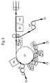
- Figure 3 illustrates schematically the formation of an unconventional double wall board having two corrugated mediums bonded at their flute tips without an intermediate liner.
- a medium 1 is corrugated between the corrugating rolls 4 and 5.
- Adhesive is applied to the flutes of medium 1 at adhesive applicator station 6 and a liner board 2 is then passed around pressure roller 7 to press the liner 2 onto the fluted medium 1 to form the single faced board 3.
- the product of this process exhibits the pressure lines.
- the medium 1 is passed in the usual way through the nip of corrugating rolls 10 and 11 and subsequently adhesives applied to the flutes of medium 1 by the adhesive applicator 12.
- the medium 1 is heated by an IR radiator 14 of this invention prior to entering the corrugating labrynth between corrugating rolls 10 and 11.
- a liner board 2 is passed over the S-wrap rollers 13 to contact and lightly adhere to the fluted medium 1.
- the adhesive bond between the medium 1 and liner 2 is bonded by using an I-R heater 14 of this invention which has a face shaped to conform to the surface of the liner as it passes over the corrugating roll 11.
- the heater 14 extends axially parallel to the roll 11.
- the single faced board 3 is thus formed without the application of excess pressure or the creation of pressure lines in the single faced board.
- the two mediums 22 and 23 are corrugated on corrugating rolls 33 and 34 and 31 and 32 respectively.
- IR radiators 44 which are axially aligned and shaped to conform to the surface of the corrugating rollers, are disposed adjacent corrugators 31 and 33 to preheat and soften the mediums 23 and 22 respectively prior to corrugation.
- adhesive is applied by adhesive station 35.
- Mediums 22 and 23 are then bonded together at their flute tips by passing through the nip of synchronised rollers 32 and 34 and the joined mediums are then passed onto the carrier roll 37.
- Adhesive is applied to the outer medium 22 at the adhesive station 38 and the liner 21 is brought into low pressure contact with the mediums by feeding through a series of feed rolls including S-wrap rolls 39.
- the mediums and liner are then carried by carrier roll 37 past the radiant energy station 44 which is axially aligned above the carrier roll 37.
- the IR radiators 44 are shaped to conform to the contour of the roll 37.
- the adhesive used by adhesive applicator 12 in Figure 2 or adhesive applicators 32 and 38 in Figure 3 may be starch or a polymeric adhesive.
- thermoplastic film capable of bonding paperboard may be fed between the nip of corrugating rolls 10 and 11 in Figure 2 or 32 and 34 in Figure 3 and subsequently subjected to IR radiation to melt the film into an adhesive layer.
- a polymer film may be fed with the liner board 2 in Figure 2 or liner 21 in Figure 3 and thus do away with the adhesive stations.
- the radiant energy sources 14 in Figure 2 and 44 in Figure 3 are incandescent sources at 2100°C emitting in a wavelength range centred at 1.2 ⁇ m.
- the surface of the carrier roll 37 acts as a reflector.
- the IR lamps are preferably located at a distance of 30 - 40 mm from the surface of the liner being bonded. Cooling air may be supplied to the lamps to prolong lamp life and provide rapid cooling down and should have an exit air pressure in the range zero to 70 mm water gauge.
- Zero pressure I-R units or "closed face" bonding units which draw in air at the operating face are an alternative which are judged to be equally effective or more effective than the I-R units cooled by air forced from within the units and discharging onto the sheet.
- adhesive is applied to exposed medium 23 and a liner 24 is applied to the single faced double flute structure by roll 42.
- the liner 24 is brought to the roll 42 over a conventional array of rollers including S-wrap feed rollers 41.
- the adhesive bond is formed by use of the radiant heaters 44 as described above.
- a reflector plate 45 is used to reflect radiation back on to the corrugated board.
- an air cushion is created over the surface of the reflector plate 45 to protect the reflective coating from abrasion by the corrugated board.
- the liner medium bonds do not exhibit pressure lines" or wash boarding and both sides of the double wall board are suitable for printing.
Landscapes
- Engineering & Computer Science (AREA)
- Mechanical Engineering (AREA)
- Physics & Mathematics (AREA)
- Thermal Sciences (AREA)
- Machines For Manufacturing Corrugated Board In Mechanical Paper-Making Processes (AREA)
- Laminated Bodies (AREA)
- Adhesives Or Adhesive Processes (AREA)
- Paper (AREA)
Abstract
Description
- This invention relates to an improved method of bonding liner boards to corrugated mediums in the manufacture of corrugated board for box manufacture.
- Conventionally, in applying liners to corrugated medium the first liner is applied at the single facer to form a single faced board and this is achieved by applying adhesive to the flute tips while the medium is contained on the corrugating roll and then applying the liner under pressure and heat. The combination of heat from the corrugating roll and pressure roll and mechanical pressure itself forms the first liner to medium bond. Subsequently, the single face board is passed to a double facer or double backer where adhesive is applied to flute tips and the board passed over a series of steam heated platens to bond the second liner. Pressure is also applied by a transport belt on top of the board and a series of small rollers riding on that belt. Travel of the double face board through the double facer or double backer is assisted by sandwich belts after the steam heated platens.
- The size of the plant and the length of the production floor is quite long in conventional plant for producing corrugated board. The heating platens are of extensive length to ensure sufficient curing of the adhesive bond as the board passes over the platens at speeds of up to 300 to 400 metres per minute.
- Another characteristic of conventional corrugated board is that of "pressure lines" which result from the pressure applied by the pressure roll at the single facer. This is compounded by "washboarding" which is the effect of the adhesive, when drying, drawing the liner out of its linearity. These effects make the board unsuitable for high quality printing on that side.
- It is an object of this invention to improve the quality of corrugated board and decrease the size of the plant required to produce board at commercially acceptable speeds.
- To this end the present invention provides a method of forming corrugated paperboard in which at least one liner is applied to the corrugated medium using low mechanical pressure and the adhesive bonding is achieved with the application of radiant energy at a wavelength for which water, paper and adhesive have a low absorption co-efficient. Preferably the wavelength is in the near infrared region of 1.0 to 2.1 microns more preferably 1.0 to 1.5 microns.
- The selection of the wavelength range is critical to this invention. Radiant heaters have been proposed previously for curing adhesives in corrugated board and laminates but the wavelengths used have resulted in absorption of the radiant energy near the surface of the paperboard and the heat input into tie adhesive layer has been by conduction through the paper. This did not radically improve the speed of bond development and there was little advantage compared to the use of conventional methods of heat input. For example US Patents 4169007 and 4589944 propose the use of IR-radiation in heating corrugated board and adhesives but without avoiding use of pressure or significantly reducing the curing time. US-A-4169007 discloses the use of radiation with wavelengths within the mange 2.6 to 3.5 microns for making single face board but without the aforesaid advantages of this invention.
- Tabulated data supplied by IR equipment suppliers, show that the percentage energy radiated within the range 1.0 to 1.5 microns and 2.5 to 3.5 microns varies with the peak wavelength transmission as follows.
Peak wavelength Source Temperature °C % Energy in 1.0 - 1.5 micron wavelength % Energy in 2.5 to 3.5 micron range 3.04 675 1.0 17.5 2.64 816 2.2 23.8 2.35 954 4.0 24.5 1.75 1370 13.6 21.5 1.50 1650 19.4 18.2 1.23 2065 23.5 13.6 1.05 2480 28.9 9.2 - An infra-red absorption spectrum, as supplies by the IR lamp suppliers, for a typical paper sheet of 185 gsm basis weight, shows that in the 2.5 to 3.5 micron wavelength range only 5% of the incident radiation is transmitted and 95% is absorbed to generate heat in the paper. In the 1.0 to 2.1 micron wavelength range 41.0% of the incident radiation is transmitted. Based on these figures, 18.2% of the radiant energy is then available for heating and gelling the starch glue, using the preferred 1.0 to 2.1 micron wavelength range, whereas only 0.7% of the radiant energy is available for this purpose in the 2.5 to 3.5 micron range which is the range recommended in US Patent 4,169,007.
- Our use of IR is to effectively utilise the transmitted element.
- It is a feature of thermal radiation as described by the laws of Stefan-Boltzmann and Wien that the radiant emittance of the source of thermal energy is proportional to the fourth power of the source temperature and that the energy is emitted over a range of wavelengths. The dominant wavelength is inversely proportional to the source temperature.
- Infra-red radiation from a thermal source ranging in temperature from 1100°C to 2300°C with peak wavelengths ranging between 2.1 and 1.0 microns is the preferred radiation for effectively bonding liners and mediums. At these wavelengths paper, water and adhesives have a low co-efficient of absorption with the energy absorbed increasing with increasing thickness of paper and adhesive film. The radiant thermal energy therefore penetrates deep into the paper structure and into the adhesive film or bead leading to rapid temperature rise of the adhesive and throughout the paper structure and the adhesive. This results in rapid gelling of adhesive and therefore rapid bond development. The high concentration of water in the adhesive film or bead in particular contributes to a high energy absorption and temperature rise in the glue. Totally transmitted radiation is reflected back through the paper layers and the adhesive film or beads by the metal surface against which the paper rests or by reflector plates situated opposite the source of radiant energy.
- At 1100°C to 2300°C temperature range, the radiant emittance of the source is sufficiently high to effectively bond the product components at required commercially viable operating speeds to make practicable the use of small radiating areas required by the constraints of the commercial corrugator design.
- It is preferred that the IR radiators are disposed axially along the rollers and not tangentially. The amount of energy for bonding may be reduced significantly by locating the lamps axially and parallel to the sheet surface. Such an arrangement allows the bank of I-R lamps to conform to the sheet which passes past the IR banks. Such conformance results in higher efficiency and has reduced the amount of energy used in bonding by 60%. The facility to conform to curved surfaces allows concentration of the IR beam and application to areas where space is a limitation.
- Preferably the air pressure at the face of the board adjacent the radiant energy source should be as close to ambient pressure as possible.
- In another aspect of this invention infra-red radiation is used instead of steam heated rollers to prepare mediums for corrugation.
- The traditional method of heating and softening the mediums to assist in their conforming to the flute profiles of the corrugating rolls and maintaining that conformance is to heat the rolls by steam injection into roll bodies. With the use of high intensity infra-red energy applied to the mediums before they enter the corrugating labyrinth equivalent heating and softening of the sheets can be obtained. The high intensity short wavelength unit has a tuning range 1.0 to 2.5 mcirons which is used to optimise the heating and softening of variable thickness paper sheets.
- Another advantage is a significant, if not total, reduction in the use of steam for heating corrugating roll bodies and avoiding the need to manufacture the corrugating rolls as pressure vessels. This avoidance also increases the rigidity of the roll bodies and trunnions so reducing roll vibration.
- The use of high intensity electrical energy does involve installation of additional transformer capacity, cabling and switchgear.
- Conventionally starch or starch based water soluble adhesives have been used for bonding corrugated boards. Starch adhesives are quite acceptable for use with the present invention and curing times are greatly decreased. However, polymeric adhesives are also suitable and provide an adequate bond comparable or superior to that of starch based adhesives.
- The various aspects of this invention are applicable to conventional corrugated board manufacture but is also applicable to the production of unconventional board having two intermediate corrugated mediums bonded at their flute tips. This type of board and methods of manufacture are described in European Patent Specifications 213957, 279609 and Applications 88311884.6 and 89903961.4.
- The invention will be further explained with reference to the drawings in which Figure 1 is a schematic view of a recently proposed conventional single facer unit, Figure 2 is a schematic view of the single facer unit according to this invention and Figure 3 illustrates schematically the formation of an unconventional double wall board having two corrugated mediums bonded at their flute tips without an intermediate liner.
- In the conventional single facer of Figure 1 a
medium 1 is corrugated between thecorrugating rolls 4 and 5. Adhesive is applied to the flutes ofmedium 1 at adhesive applicator station 6 and aliner board 2 is then passed aroundpressure roller 7 to press theliner 2 onto thefluted medium 1 to form the single facedboard 3. - The product of this process exhibits the pressure lines.
- In Figure 2 the
medium 1 is passed in the usual way through the nip ofcorrugating rolls medium 1 by theadhesive applicator 12. Themedium 1 is heated by anIR radiator 14 of this invention prior to entering the corrugating labrynth betweencorrugating rolls - A
liner board 2 is passed over the S-wrap rollers 13 to contact and lightly adhere to thefluted medium 1. The adhesive bond between themedium 1 andliner 2 is bonded by using anI-R heater 14 of this invention which has a face shaped to conform to the surface of the liner as it passes over thecorrugating roll 11. Theheater 14 extends axially parallel to theroll 11. The single facedboard 3 is thus formed without the application of excess pressure or the creation of pressure lines in the single faced board. - In Figure 3 the production of unconventional board is illustrated in which the two
mediums liner boards - The two
mediums corrugating rolls IR radiators 44 which are axially aligned and shaped to conform to the surface of the corrugating rollers, are disposedadjacent corrugators 31 and 33 to preheat and soften themediums adhesive station 35.Mediums synchronised rollers 32 and 34 and the joined mediums are then passed onto thecarrier roll 37. Adhesive is applied to the outer medium 22 at theadhesive station 38 and theliner 21 is brought into low pressure contact with the mediums by feeding through a series of feed rolls including S-wrap rolls 39. - After applying the liner the mediums and liner are then carried by
carrier roll 37 past theradiant energy station 44 which is axially aligned above thecarrier roll 37. TheIR radiators 44 are shaped to conform to the contour of theroll 37. - The adhesive used by
adhesive applicator 12 in Figure 2 oradhesive applicators 32 and 38 in Figure 3 may be starch or a polymeric adhesive. Alternatively thermoplastic film capable of bonding paperboard may be fed between the nip of corrugating rolls 10 and 11 in Figure 2 or 32 and 34 in Figure 3 and subsequently subjected to IR radiation to melt the film into an adhesive layer. Similarly a polymer film may be fed with theliner board 2 in Figure 2 orliner 21 in Figure 3 and thus do away with the adhesive stations. - It should be noted that the apparatus as shown in Figure 3 can be used to make conventional corrugated board by simply not using corrugating rollers 31 and 32.
- The
radiant energy sources 14 in Figure 2 and 44 in Figure 3 are incandescent sources at 2100°C emitting in a wavelength range centred at 1.2 µm. The surface of thecarrier roll 37 acts as a reflector. - The IR lamps are preferably located at a distance of 30 - 40 mm from the surface of the liner being bonded. Cooling air may be supplied to the lamps to prolong lamp life and provide rapid cooling down and should have an exit air pressure in the range zero to 70 mm water gauge.
- Zero pressure I-R units or "closed face" bonding units which draw in air at the operating face are an alternative which are judged to be equally effective or more effective than the I-R units cooled by air forced from within the units and discharging onto the sheet.
- After leaving the
carrier roll 37 adhesive is applied to exposedmedium 23 and aliner 24 is applied to the single faced double flute structure byroll 42. Theliner 24 is brought to theroll 42 over a conventional array of rollers including S-wrap feed rollers 41. - The adhesive bond is formed by use of the
radiant heaters 44 as described above. - In the case of the second liners a reflector plate 45 is used to reflect radiation back on to the corrugated board. Preferably an air cushion is created over the surface of the reflector plate 45 to protect the reflective coating from abrasion by the corrugated board.
- At speeds of 80 to 100 metres per minute bonding times of less than a second can be achieved compared to conventional bonding times of up to 4 seconds at the double backer station.
- By the use of this invention the liner medium bonds do not exhibit
 pressure lines" orwash boarding
 and both sides of the double wall board are suitable for printing.
 - The key process advantages are:
- 1. Absence of the steam heated platen unit which occupies extensive floor space on the conventional line.
- 2. Absence of the "bridge" between single facer and double backer which requires transfer belts and facilities to assist feeding to the double backer. Both
advantages - 3. Reduced losses as a conventional machine stoppage results in board remaining in the steam platen area and overheating to lose required quality.
- 4. Reduced adhesive usage compared to conventional double backers.
Claims (4)
- A method of forming corrugated paperboard structures in which adhesive is applied to one paperboard layer (1;22,23) and another paperboard layer (2;21,22,24) is brought into pressure contact with it and infra-red heat is applied to the layers to cure the adhesive bond characterised in that the adhesive used is rendered effective by the application of low mechanical pressure and exposure to a thermal radiation source (14;44) ranging from 1100°C to 2300°C emitting a dominant wavelength between 2.1 and 1.0 microns to improve the speed of bond development between the layers (1,2;22,23;21,22;23,24).
- A method as claimed in claim 1 wherein at least one of the layers is a corrugated paperboard medium (1;22,23) and the other layer is a paperboard liner (2;21,24) or another corrugated paperboard medium.
- A method as claimed in claim 1 or claim 2 in which the radiant energy source (14;44) is an infra-red source aligned axially of corrugating (10,11;31,32,33, 34) or carrier (37) rolls and parallel to the paperboard layers (1,2;21,22,23,24).
- A corrugated paperboard (1,2;21,22,23,24) composed of at least one liner (2;21,24) and at least one corrugated medium (1;22,23) which exhibits reduced pressure lines and washboarding, formed by a method as defined in claim 2 or claim 3 and claim 2.
Applications Claiming Priority (5)
| Application Number | Priority Date | Filing Date | Title |
|---|---|---|---|
| AU7849/91 | 1991-08-19 | ||
| AUPK784991 | 1991-08-19 | ||
| AU9949/91 | 1991-12-10 | ||
| AUPK994991 | 1991-12-10 | ||
| PCT/AU1992/000439 WO1993003913A1 (en) | 1991-08-19 | 1992-08-18 | Manufacturing corrugated board |
Publications (3)
| Publication Number | Publication Date |
|---|---|
| EP0602104A1 EP0602104A1 (en) | 1994-06-22 |
| EP0602104A4 EP0602104A4 (en) | 1994-07-06 |
| EP0602104B1 true EP0602104B1 (en) | 1997-01-08 |
Family
ID=25644098
Family Applications (1)
| Application Number | Title | Priority Date | Filing Date |
|---|---|---|---|
| EP92918375A Expired - Lifetime EP0602104B1 (en) | 1991-08-19 | 1992-08-18 | Manufacturing corrugated board |
Country Status (12)
| Country | Link |
|---|---|
| US (1) | US5498304A (en) |
| EP (1) | EP0602104B1 (en) |
| JP (1) | JP3385021B2 (en) |
| AT (1) | ATE147324T1 (en) |
| AU (1) | AU653431B2 (en) |
| CA (1) | CA2112116C (en) |
| DE (1) | DE69216625T2 (en) |
| DK (1) | DK0602104T3 (en) |
| FI (1) | FI109774B (en) |
| HK (1) | HK1005439A1 (en) |
| NO (1) | NO306202B1 (en) |
| WO (1) | WO1993003913A1 (en) |
Families Citing this family (17)
| Publication number | Priority date | Publication date | Assignee | Title |
|---|---|---|---|---|
| FR2697201B1 (en) * | 1992-10-28 | 1994-12-16 | Saint Gobain Papier Bois Gie C | Method and device for manufacturing corrugated cardboard. |
| DE19506778A1 (en) * | 1995-02-27 | 1996-08-29 | Bhs Corr Masch & Anlagenbau | Process for the production of corrugated cardboard |
| AUPN367095A0 (en) * | 1995-06-20 | 1995-07-13 | Amcor Limited | Corrugated board manufacture |
| GB2303385A (en) * | 1995-07-14 | 1997-02-19 | Scm Container Mach Ltd | Apparatus for producing corrugated paperboard |
| US5788803A (en) * | 1996-10-16 | 1998-08-04 | Interfic, Inc. | Corrugated paperboard manufacturing apparatus with controllable preheating |
| US5837974A (en) * | 1996-10-16 | 1998-11-17 | Interfic, Inc. | Corrugated paperboard manufacturing apparatus with board profile monitoring and related methods |
| US5902502A (en) * | 1996-10-16 | 1999-05-11 | Interfic, Inc. | Corrugated paperboard manufacturing apparatus and related methods |
| US5847362A (en) * | 1996-10-16 | 1998-12-08 | Interfic, Inc. | Corrugated paperboard manufacturing apparatus providing controllable heat and related methods |
| US6149751A (en) * | 1996-11-01 | 2000-11-21 | Marquip, Inc. | Low pressure single facer |
| DE19716706A1 (en) * | 1997-04-21 | 1998-10-29 | Bhs Corr Masch & Anlagenbau | Machine for producing corrugated cardboard length coated on one side |
| US6007658A (en) * | 1998-03-04 | 1999-12-28 | Westvaco Corporation | Carton sealing method utilizing radiation curable pressure-sensitive adhesives |
| US20030041963A1 (en) * | 2001-08-20 | 2003-03-06 | Lie-Zhong Gong | Reactivatable adhesives |
| US20040164134A1 (en) * | 2003-02-22 | 2004-08-26 | Lie-Zhong Gong | Packaging system |
| US7517307B2 (en) * | 2005-01-21 | 2009-04-14 | Kraft Foods Global Brands Llc | Method of assembling a carton blank into a carton |
| EP2792478B1 (en) * | 2013-04-19 | 2019-03-20 | BP Agnati S.r.L. | Assembly and process for manufacturing corrugated board |
| US9952160B2 (en) | 2014-04-04 | 2018-04-24 | Packaging Corporation Of America | System and method for determining an impact of manufacturing processes on the caliper of a sheet material |
| US12049058B2 (en) * | 2020-09-16 | 2024-07-30 | Packsize Llc | Systems and methods for forming dual fluted corrugated board |
Family Cites Families (14)
| Publication number | Priority date | Publication date | Assignee | Title |
|---|---|---|---|---|
| US3660200A (en) * | 1969-07-09 | 1972-05-02 | Robert E Anderson | Process for bonding preheated thermoplastic film to a dissimilar substrate |
| US4169007A (en) * | 1977-10-26 | 1979-09-25 | Flynn Drying System, Inc. | Dryer-cooling machine for producing corrugated doubleface corrugated board |
| US4419304A (en) * | 1980-07-15 | 1983-12-06 | Western Electric Company, Inc. | Method for forming seals with heat shrinkable materials |
| GB2121353B (en) * | 1982-05-28 | 1985-09-11 | Eurobond Coatings Limited | Laminating |
| FR2555101B1 (en) * | 1983-11-17 | 1987-10-23 | Martin Sa | METHOD AND DEVICE FOR MANUFACTURING A CORRUGATED CARDBOARD STRIP |
| ZA866491B (en) * | 1985-09-04 | 1987-05-27 | Amcor Ltd | Corrugated board |
| USH556H (en) * | 1985-12-02 | 1988-12-06 | Method of manufacture and machine for manufacturing subterranean wall drain | |
| BR8800608A (en) * | 1987-02-18 | 1988-09-27 | Amcor Ltd | APPARATUS AND METHOD FOR MANUFACTURING CORRUGATED PAPER WITH FACE SINGLE |
| CA1312540C (en) * | 1987-12-18 | 1993-01-12 | Peter Gordon Bennett | Forming corrugated board structures |
| JP2724894B2 (en) * | 1988-03-31 | 1998-03-09 | アムコー・リミテツド | Single-sided corrugated cardboard manufacturing equipment |
| WO1990000970A1 (en) * | 1988-07-28 | 1990-02-08 | Swartz Henry D | Bonding of plastic and plastic matrix composite materials |
| US4950348A (en) * | 1988-10-13 | 1990-08-21 | Elva Induksjon A/S | Method for joining structural elements by heating of a binder |
| SE465214B (en) * | 1990-01-16 | 1991-08-12 | Tetra Pak Holdings Sa | SETTLE TO HEAT PART OF CURRENT MATERIALS |
| US5035045A (en) * | 1990-09-10 | 1991-07-30 | Globe-Union Inc. | Method of joining bipolar battery frames |
-
1992
- 1992-08-18 DE DE69216625T patent/DE69216625T2/en not_active Expired - Fee Related
- 1992-08-18 EP EP92918375A patent/EP0602104B1/en not_active Expired - Lifetime
- 1992-08-18 US US08/190,146 patent/US5498304A/en not_active Expired - Fee Related
- 1992-08-18 HK HK98104576A patent/HK1005439A1/en not_active IP Right Cessation
- 1992-08-18 JP JP50396893A patent/JP3385021B2/en not_active Expired - Fee Related
- 1992-08-18 WO PCT/AU1992/000439 patent/WO1993003913A1/en not_active Ceased
- 1992-08-18 AU AU24725/92A patent/AU653431B2/en not_active Ceased
- 1992-08-18 CA CA002112116A patent/CA2112116C/en not_active Expired - Fee Related
- 1992-08-18 AT AT92918375T patent/ATE147324T1/en not_active IP Right Cessation
- 1992-08-18 DK DK92918375.4T patent/DK0602104T3/en active
-
1994
- 1994-02-17 NO NO940553A patent/NO306202B1/en unknown
- 1994-02-17 FI FI940755A patent/FI109774B/en not_active IP Right Cessation
Also Published As
| Publication number | Publication date |
|---|---|
| FI940755L (en) | 1994-02-17 |
| ATE147324T1 (en) | 1997-01-15 |
| NO940553L (en) | 1994-02-17 |
| US5498304A (en) | 1996-03-12 |
| DE69216625T2 (en) | 1997-07-31 |
| CA2112116C (en) | 2001-10-23 |
| NO306202B1 (en) | 1999-10-04 |
| WO1993003913A1 (en) | 1993-03-04 |
| FI940755A0 (en) | 1994-02-17 |
| JP3385021B2 (en) | 2003-03-10 |
| DK0602104T3 (en) | 1997-07-07 |
| AU2472592A (en) | 1993-03-16 |
| CA2112116A1 (en) | 1993-03-04 |
| EP0602104A1 (en) | 1994-06-22 |
| NO940553D0 (en) | 1994-02-17 |
| JPH06509758A (en) | 1994-11-02 |
| EP0602104A4 (en) | 1994-07-06 |
| DE69216625D1 (en) | 1997-02-20 |
| FI109774B (en) | 2002-10-15 |
| HK1005439A1 (en) | 1999-01-08 |
| AU653431B2 (en) | 1994-09-29 |
Similar Documents
| Publication | Publication Date | Title |
|---|---|---|
| US5498304A (en) | Method of manufacturing corrugated board using a thermal radiant energy source | |
| HK1005439B (en) | Manufacturing corrugated board | |
| CA1298767C (en) | Process for on-line lamination of plastic film in a corrugator for making corrugated paperboard | |
| CA1312540C (en) | Forming corrugated board structures | |
| US4589944A (en) | Process and apparatus for producing a strip of corrugated cardboard | |
| CN108501454B (en) | Multilayer corrugated board production line and production process thereof | |
| US3712843A (en) | Method and apparatus for producing corrugated board | |
| EP0279609B1 (en) | Manufacturing corrugated board | |
| TWM486545U (en) | One-side corrugated paper forming machine without internal heating | |
| CN219947481U (en) | Corrugated board wet-end production facility | |
| US5348610A (en) | Apparatus for manufacturing corrugated board | |
| JP2007030171A (en) | Method and apparatus for manufacturing corrugate cardboard | |
| JPH11503374A (en) | Corrugated cardboard manufacturing method and apparatus | |
| HK1005438B (en) | Manufacturing corrugated board | |
| HK1005438A1 (en) | Manufacturing corrugated board | |
| CN212353199U (en) | Material composite processing equipment | |
| US12552128B2 (en) | Method and apparatus for manufacturing corrugated paperboard | |
| US6782935B2 (en) | Hot laminating apparatus having single-sided transmitting and heating roller | |
| JP3492085B2 (en) | Method and apparatus for manufacturing corrugated cardboard sheet | |
| JPH0655675A (en) | Single-faced corrugated board producing machine | |
| JP4405644B2 (en) | Corrugated cardboard warpage prevention device | |
| JP2678785B2 (en) | Manufacturing method of composite corrugated board | |
| JPH06270299A (en) | Double facer in corrugated cardboard machine | |
| JP2713645B2 (en) | Corrugator | |
| JP2002113799A (en) | Method for manufacturing double side corrugated board and manufacturing device therefor |
Legal Events
| Date | Code | Title | Description |
|---|---|---|---|
| PUAI | Public reference made under article 153(3) epc to a published international application that has entered the european phase |
Free format text: ORIGINAL CODE: 0009012 |
|
| 17P | Request for examination filed |
Effective date: 19940208 |
|
| AK | Designated contracting states |
Kind code of ref document: A1 Designated state(s): AT BE CH DE DK ES FR GB GR IE IT LI LU MC NL SE |
|
| A4 | Supplementary search report drawn up and despatched | ||
| AK | Designated contracting states |
Kind code of ref document: A4 Designated state(s): AT BE CH DE DK ES FR GB GR IE IT LI LU MC NL SE |
|
| 17Q | First examination report despatched |
Effective date: 19950510 |
|
| GRAG | Despatch of communication of intention to grant |
Free format text: ORIGINAL CODE: EPIDOS AGRA |
|
| GRAH | Despatch of communication of intention to grant a patent |
Free format text: ORIGINAL CODE: EPIDOS IGRA |
|
| GRAH | Despatch of communication of intention to grant a patent |
Free format text: ORIGINAL CODE: EPIDOS IGRA |
|
| GRAA | (expected) grant |
Free format text: ORIGINAL CODE: 0009210 |
|
| AK | Designated contracting states |
Kind code of ref document: B1 Designated state(s): AT BE CH DE DK ES FR GB GR IE IT LI LU MC NL SE |
|
| PG25 | Lapsed in a contracting state [announced via postgrant information from national office to epo] |
Ref country code: NL Free format text: LAPSE BECAUSE OF FAILURE TO SUBMIT A TRANSLATION OF THE DESCRIPTION OR TO PAY THE FEE WITHIN THE PRESCRIBED TIME-LIMIT Effective date: 19970108 Ref country code: LI Effective date: 19970108 Ref country code: GR Free format text: LAPSE BECAUSE OF FAILURE TO SUBMIT A TRANSLATION OF THE DESCRIPTION OR TO PAY THE FEE WITHIN THE PRESCRIBED TIME-LIMIT Effective date: 19970108 Ref country code: ES Free format text: THE PATENT HAS BEEN ANNULLED BY A DECISION OF A NATIONAL AUTHORITY Effective date: 19970108 Ref country code: CH Effective date: 19970108 Ref country code: BE Effective date: 19970108 Ref country code: AT Effective date: 19970108 |
|
| REF | Corresponds to: |
Ref document number: 147324 Country of ref document: AT Date of ref document: 19970115 Kind code of ref document: T |
|
| REG | Reference to a national code |
Ref country code: CH Ref legal event code: EP |
|
| REF | Corresponds to: |
Ref document number: 69216625 Country of ref document: DE Date of ref document: 19970220 |
|
| REG | Reference to a national code |
Ref country code: IE Ref legal event code: FG4D Free format text: 71449 |
|
| ITF | It: translation for a ep patent filed | ||
| ET | Fr: translation filed | ||
| NLV1 | Nl: lapsed or annulled due to failure to fulfill the requirements of art. 29p and 29m of the patents act | ||
| REG | Reference to a national code |
Ref country code: DK Ref legal event code: T3 |
|
| REG | Reference to a national code |
Ref country code: CH Ref legal event code: PL |
|
| PG25 | Lapsed in a contracting state [announced via postgrant information from national office to epo] |
Ref country code: IE Free format text: LAPSE BECAUSE OF NON-PAYMENT OF DUE FEES Effective date: 19970818 |
|
| PG25 | Lapsed in a contracting state [announced via postgrant information from national office to epo] |
Ref country code: LU Free format text: LAPSE BECAUSE OF NON-PAYMENT OF DUE FEES Effective date: 19970831 |
|
| PLBE | No opposition filed within time limit |
Free format text: ORIGINAL CODE: 0009261 |
|
| PGFP | Annual fee paid to national office [announced via postgrant information from national office to epo] |
Ref country code: IE Payment date: 19971231 Year of fee payment: 6 |
|
| 26N | No opposition filed | ||
| PG25 | Lapsed in a contracting state [announced via postgrant information from national office to epo] |
Ref country code: MC Free format text: LAPSE BECAUSE OF NON-PAYMENT OF DUE FEES Effective date: 19980228 |
|
| REG | Reference to a national code |
Ref country code: FR Ref legal event code: CA |
|
| REG | Reference to a national code |
Ref country code: IE Ref legal event code: MM4A |
|
| REG | Reference to a national code |
Ref country code: GB Ref legal event code: IF02 |
|
| PGFP | Annual fee paid to national office [announced via postgrant information from national office to epo] |
Ref country code: SE Payment date: 20050804 Year of fee payment: 14 |
|
| PGFP | Annual fee paid to national office [announced via postgrant information from national office to epo] |
Ref country code: FR Payment date: 20050809 Year of fee payment: 14 |
|
| PGFP | Annual fee paid to national office [announced via postgrant information from national office to epo] |
Ref country code: DE Payment date: 20050811 Year of fee payment: 14 |
|
| PGFP | Annual fee paid to national office [announced via postgrant information from national office to epo] |
Ref country code: DK Payment date: 20050815 Year of fee payment: 14 |
|
| PGFP | Annual fee paid to national office [announced via postgrant information from national office to epo] |
Ref country code: GB Payment date: 20050817 Year of fee payment: 14 |
|
| PG25 | Lapsed in a contracting state [announced via postgrant information from national office to epo] |
Ref country code: SE Free format text: LAPSE BECAUSE OF NON-PAYMENT OF DUE FEES Effective date: 20060819 |
|
| PG25 | Lapsed in a contracting state [announced via postgrant information from national office to epo] |
Ref country code: DK Free format text: LAPSE BECAUSE OF NON-PAYMENT OF DUE FEES Effective date: 20060831 |
|
| PGFP | Annual fee paid to national office [announced via postgrant information from national office to epo] |
Ref country code: IT Payment date: 20060831 Year of fee payment: 15 |
|
| PG25 | Lapsed in a contracting state [announced via postgrant information from national office to epo] |
Ref country code: DE Free format text: LAPSE BECAUSE OF NON-PAYMENT OF DUE FEES Effective date: 20070301 |
|
| REG | Reference to a national code |
Ref country code: DK Ref legal event code: EBP |
|
| EUG | Se: european patent has lapsed | ||
| GBPC | Gb: european patent ceased through non-payment of renewal fee |
Effective date: 20060818 |
|
| REG | Reference to a national code |
Ref country code: FR Ref legal event code: ST Effective date: 20070430 |
|
| PG25 | Lapsed in a contracting state [announced via postgrant information from national office to epo] |
Ref country code: GB Free format text: LAPSE BECAUSE OF NON-PAYMENT OF DUE FEES Effective date: 20060818 |
|
| PG25 | Lapsed in a contracting state [announced via postgrant information from national office to epo] |
Ref country code: FR Free format text: LAPSE BECAUSE OF NON-PAYMENT OF DUE FEES Effective date: 20060831 |
|
| PG25 | Lapsed in a contracting state [announced via postgrant information from national office to epo] |
Ref country code: IT Free format text: LAPSE BECAUSE OF NON-PAYMENT OF DUE FEES Effective date: 20070818 |