EP0601552B1 - Electric coffee machine - Google Patents
Electric coffee machine Download PDFInfo
- Publication number
- EP0601552B1 EP0601552B1 EP93119739A EP93119739A EP0601552B1 EP 0601552 B1 EP0601552 B1 EP 0601552B1 EP 93119739 A EP93119739 A EP 93119739A EP 93119739 A EP93119739 A EP 93119739A EP 0601552 B1 EP0601552 B1 EP 0601552B1
- Authority
- EP
- European Patent Office
- Prior art keywords
- filter cup
- wall
- water container
- coffee machine
- contour
- Prior art date
- Legal status (The legal status is an assumption and is not a legal conclusion. Google has not performed a legal analysis and makes no representation as to the accuracy of the status listed.)
- Expired - Lifetime
Links
- XLYOFNOQVPJJNP-UHFFFAOYSA-N water Substances O XLYOFNOQVPJJNP-UHFFFAOYSA-N 0.000 claims description 42
- 238000007373 indentation Methods 0.000 claims 1
- 238000004519 manufacturing process Methods 0.000 description 4
- 238000003780 insertion Methods 0.000 description 2
- 230000037431 insertion Effects 0.000 description 2
- 238000007789 sealing Methods 0.000 description 2
- 238000010276 construction Methods 0.000 description 1
- 238000009434 installation Methods 0.000 description 1
Images


Classifications
-
- A—HUMAN NECESSITIES
- A47—FURNITURE; DOMESTIC ARTICLES OR APPLIANCES; COFFEE MILLS; SPICE MILLS; SUCTION CLEANERS IN GENERAL
- A47J—KITCHEN EQUIPMENT; COFFEE MILLS; SPICE MILLS; APPARATUS FOR MAKING BEVERAGES
- A47J31/00—Apparatus for making beverages
- A47J31/44—Parts or details or accessories of beverage-making apparatus
- A47J31/4403—Constructional details
- A47J31/446—Filter holding means; Attachment of filters to beverage-making apparatus
Definitions
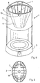
- the invention relates to an electric coffee machine with a filter cup which can be inserted into a space defined by a water container and which has a substantially conically tapering outer contour, wall sections of the water container being adapted to the outer contour of the filter cup.
- Such a coffee machine has become known, for example, from DE-A-31 04 542.
- the filter cup has a horizontal web surface, via which the filter cup can be inserted into corresponding grooves or steps in the body of the water container so that it hangs over the edge. This insertion of the filter cup over the land surface into the grooves of the water container requires a certain amount of attention from a user in order to orient and insert the land surface with respect to the grooves.
- the outer wall of the filter cup starting from an essentially flat cup base, has an oval, in particular elliptical cross-sectional contour, which gradually changes to a circular cross-sectional contour towards the upper edge and that the filter cup sits in the water container with the correct position in a form-fitting manner , wherein the first centering means are formed by the positive connection between the oval, in particular elliptical, wall cross-sectional contour of the filter cup and the matching, also oval, in particular elliptical, wall cross-sectional contour of the water container.
- the basic idea of the invention is to make wall sections of the water container so adapted to the outer contour of the filter cup that the latter sits positively in the water container in the correct position.
- the filter cup in the water container Due to the positive locking of the filter cup in the water container and the oval or elliptical filter cup wall contour according to the invention and the correspondingly adapted water container wall, it is possible in a particularly simple manner to use the filter cup without further aids such as web surfaces or grooves in the space defined by the water container. Due to the special cross-sectional contour of the filter cup and the water container, the orientation of the filter cup in the water container is only possible in two insertion positions. One of the two installation positions can then be easily favored using a handle or an engagement recess on the filter cup.
- the coffee drain of the filter cup is liquid-tight separated from the water in the water tank.
- the filter cup has a handle on a front side, for example, according to a preferred development of the invention, the filter cup in the area of the wall section adjoining its bottom and the wall section of the water container which is adapted to it each have cooperating centering means which self-center the filter cup in the direction of the Water container cause defined space, so that in particular the handle comes to lie directly forward.
- the front thereof partially protrude from a front wall of the water tank.
- said front wall has a pre-design an opening opening upwards with a parabolic contour.
- this front part of the filter cup i. H. whose outer wall is form-fitting with the parabolic edge of the cutout in the front wall of the water tank.
- Further centering means can be formed by a groove in the area of the rear wall of the filter cup, this groove running in the direction of a surface line of the filter cup and interacting with a corresponding knob on the wall of the water container adjacent to it.
- the described form-fitting seat of the filter cup in the space defined by the water container advantageously enables a compact structure and cost-effective production of the electric coffee machine.
- the preferably provided centering means advantageously ensures that the filter cup assumes the correct fit in every case.
- a water container 4 is provided above a base 5 with an oval, in particular elliptical, outer contour.
- the water tank 4 is enclosed by a front wall 3 and a rear wall 9.
- the front wall 3 and an intermediate wall 8 form a receptacle or a seat for a filter cup, not shown in FIG. 1, which can be inserted into this receptacle from above.
- the front wall 3 is located above a recess projecting into the lower part of the water container, into which the carafe (not shown) can be partially adjusted. In addition, the front wall 3 is offset from the front edge of the base 5 to the rear.
- the lower section 8 ′ of the intermediate wall 8 and the contour of the inner part 3 of the front wall 3 are elliptical, whereas the contour of the intermediate wall 8 is circular in its upper section with a radius R 1 .
- the outer contour of the front wall 3 has a larger radius of curvature R 2 > R 1 .
- the filter cup seat has a lower opening E with an oval, in particular elliptical, contour, as clearly shown in FIG.
- the section shown in FIG. 2 through the space defined by the water tank 4 along the section line II-II in FIG. 1 clearly shows the essentially conically tapering shape of that of the through the intermediate wall 8, 8 'and the inner part 3' of the front wall 3 formed filter cup seat.
- the filter cup 2 is shown in its correct seat in this receptacle with dashed lines.
- the front wall 3 is cut obliquely along a sectional plane, so that the filter cup 2 with the upper part of its front wall 16 looks out of this cutout 6 to the front.
- this cutout 6 is cut out along an oblique cutting plane, so that an approximately parabolic edge results. (Fig. 6).
- the outer wall of the filter cup 2 is adapted to the course of the inner surfaces of the intermediate wall 8, 8 'and the front wall 3', so that the filter cup sits in a form-fitting manner.
- the filter cup 2 is explained in more detail below with reference to FIGS. 3 to 5.
- the filter cup 2 is shown in a top view in FIG.
- the contour of the upper section 18 of the filter cup wall is essentially circular, but has a recessed grip 19 on the front of the filter cup. The edge bulges outward somewhat at this point.
- a groove 11 running along a surface line, which is molded in from the outside and which has an opening 12 to the inside of the filter cup 2.
- the contour of this wall section 18 ' is oval, in particular elliptical, so that the outer dimensions of the filter cup 2 correspond to the dimensions of the filter cup seat formed by the intermediate wall 8, 8' and the front wall 3 in the space of Water tank 4 is adapted positively.
- the bottom 7 is essentially flat and has in its center a valve 20 which opens under mechanical pressure from the lid of the coffee carafe and of which a valve member 23 and a sealing ring 21 can be seen.
- the bottom 7 is elliptical in plan view and does not protrude beyond the wall section 18 '.
- ribs 26 can be provided on the inner surface of the filter cup wall 18, 18 '.
- FIG. 4 represents a section along the section line IV-IV in FIG.
- the aforementioned pressure valve 20 consists of a plunger 25 biased by a coil spring 22, which at its other end, the is located within the filter cup, has a valve member 23 which seals against a sealing ring 21 serving as a valve seat.
- FIG. 5 shows a representation of a section along the section line V-V in FIG. 4.
- FIG. 6 finally shows the preferred embodiment of the coffee machine according to the invention in a perspective front view, the coffee carafe and the lid being omitted.
- FIG. 6 shows particularly clearly that the front upper part of the filter cup 2 looks forward from the cutout 6 formed in the front wall 3, the parabolic edge of the cutout 6 being form-fitting with the outer wall of the filter cup 2.
- the filter cup sits in a form-fitting manner in wall sections of the space defined by the water container, which results in a compact construction and an inexpensive manufacture of the filter machine.
Landscapes
- Engineering & Computer Science (AREA)
- Food Science & Technology (AREA)
- Apparatus For Making Beverages (AREA)
Description
Die Erfindung betrifft eine elektrische Kaffeemaschine mit einem in einen durch einen Wasserbehälter definierten Raum einsetzbaren Filterbecher, der eine im wesentlichen konisch nach unten zulaufende Außenkontur hat, wobei Wandabschnitte des Wasserbehälters an die Außenkontur des Filterbechers angepaßt sind.The invention relates to an electric coffee machine with a filter cup which can be inserted into a space defined by a water container and which has a substantially conically tapering outer contour, wall sections of the water container being adapted to the outer contour of the filter cup.
Eine derartige Kaffeemaschine ist beispielsweise durch die DE-A-31 04 542 bekanntgeworden.Such a coffee machine has become known, for example, from DE-A-31 04 542.
Bei modernen Kaffeemaschinen ist man bestrebt, die Forderungen nach ästhetisch gefälligem Aussehen, kompakter Bauweise und kostengünstiger Herstellung in effektiver Weise miteinander zu kombinieren. Dabei hat es sich als günstig herausgestellt, statt des früher separat auf die Karaffe aufgesetzten Filters, den Filterbecher in den durch den Wasserbehälter definierten Raum einzubeziehen. Manche Hersteller bekannter Kaffeemaschinen sind dabei den Weg gegangen, den Filterbecher in eine über die Karaffe schwenkbare, separate Aufnahme einzusetzen, wobei diese Aufnahme dann dafür sorgt, daß der Auslauf des Filterbechers über den Einlauf der Karaffe zu liegen kommt.In modern coffee machines, efforts are made to effectively combine the demands for an aesthetically pleasing appearance, compact design and cost-effective production. It turned out to be advantageous to include the filter cup in the space defined by the water container instead of the filter that was previously separately attached to the carafe. Some manufacturers of known coffee machines have gone the way of inserting the filter cup into a separate receptacle that can be pivoted over the carafe, this receptacle then ensuring that the outlet of the filter cup comes to lie over the inlet of the carafe.
Die separate Filterbecheraufnahme und der dafür notwendige Schwenkmechanismus verteuern jedoch die Herstellungskosten der Kaffeemaschine.However, the separate filter cup holder and the necessary swivel mechanism make the production costs of the coffee machine more expensive.
Bei der aus der DE-A-31 04 542 bekannten elektrischen Kaffeemaschine ist in dem Wasserbehälter eine spezielle horizontale Führung für den Filterbecher vorgesehen. Der Filterbecher weist eine horizontale Stegfläche auf, über die der Filterbecher in entsprechende Nuten oder Stufen im Körper des Wasserbehälters so einschiebbar ist, daß er über der Kante hängt. Dieses Einführen des Filterbechers über die Stegfläche in die Nuten des Wasserbehälters erfordert von einem Benutzer eine gewisse Aufmerksamkeit, um die Stegfläche bezüglich den Nuten zu orientieren und einzuführen.In the electric coffee machine known from DE-A-31 04 542 there is a special horizontal one in the water container Guide provided for the filter cup. The filter cup has a horizontal web surface, via which the filter cup can be inserted into corresponding grooves or steps in the body of the water container so that it hangs over the edge. This insertion of the filter cup over the land surface into the grooves of the water container requires a certain amount of attention from a user in order to orient and insert the land surface with respect to the grooves.
Weiterhin ist aus der DE-A-26 05 957 eine elektrische Kaffeemaschine mit einer formschlüssigen Verbindung des Filterbechers in dem Wasserbehälter bekannt. Der Filterbecher ist mit einem keilförmigen Haken in Aussparungen am Wasserbehälter eingehängt, wobei sich der Filterrand auf eine Filterauflage des Gehäuses stützt. Der Wasserbehälter ist über einen halbkreisförmigen Mantel an die Wandkontur des Filterbechers angepaßt.Furthermore, from DE-A-26 05 957 an electric coffee machine with a positive connection of the filter cup in the water tank is known. The filter cup is hooked into a recess on the water tank with a wedge-shaped hook, the filter rim being supported on a filter support of the housing. The water tank is adapted to the wall contour of the filter cup via a semicircular jacket.
Es ist deshalb Aufgabe der Erfindung, eine gattungsgemäße elektrische Kaffeemaschine dahingehend weiterzubilden, daß die Anordnung des Filterbechers in der Kaffeemaschine ohne große Aufmerksamkeit erfolgen kann.It is therefore an object of the invention to further develop a generic electric coffee machine in such a way that the filter cup can be arranged in the coffee machine without great attention.
Diese Aufgabe wird dadurch gelöst, daß die Außenwand des Filterbechers ausgehend von einem im wesentlichen flachen Becherboden eine ovale, insbesondere elliptische Querschnittskontur aufweist, die allmählich zu einer kreisförmigen Querschnittskontur in Richtung zum oberen Rand hin übergeht und daß der Filterbecher im Wasserbehälter bei korrekter Stellung formschlüssig sitzt, wobei erste Zentriermittel durch den Formschluß zwischen der ovalen, insbesondere ellipitischen Wandquerschnittskontur des Filterbechers und der daran angepaßten, ebenfalls ovalen, insbesondere elliptischen Wandquerschnittskontur des Wasserbehälters gebildet sind.This object is achieved in that the outer wall of the filter cup, starting from an essentially flat cup base, has an oval, in particular elliptical cross-sectional contour, which gradually changes to a circular cross-sectional contour towards the upper edge and that the filter cup sits in the water container with the correct position in a form-fitting manner , wherein the first centering means are formed by the positive connection between the oval, in particular elliptical, wall cross-sectional contour of the filter cup and the matching, also oval, in particular elliptical, wall cross-sectional contour of the water container.
Der Grundgedanke der Erfindung besteht darin, Wandabschnitte des Wasserbehälters so angepaßt an die Außenkontur des Filterbechers zu gestalten, daß letzterer in dem Wasserbehälter bei korrekter Stellung formschlüssig sitzt.The basic idea of the invention is to make wall sections of the water container so adapted to the outer contour of the filter cup that the latter sits positively in the water container in the correct position.
Durch den Formschluß des Filterbechers im Wasserbehälter und durch die erfindungsgemäße ovale bzw. elliptische Filterbecher-Wandkontur und entsprechend daran angepaßter Wasserbehälterwand ist es auf besonders einfache Weise möglich, den Filterbecher ohne weitere Hilfsmittel wie Stegflächen oder Nuten in den durch den Wasserbehälter definierten Raum einzusetzen. Durch die besondere Querschnittskontur des Filterbechers und des Wasserbehälters ist dabei die Orientierung des Filterbechers in dem Wasserbehälter nur in zwei Einsetzpositionen möglich. Über einen Griff oder eine Eingriffsmulde am Filterbecher kann eine der beiden Einbaupositionen dann leicht favorisiert werden.Due to the positive locking of the filter cup in the water container and the oval or elliptical filter cup wall contour according to the invention and the correspondingly adapted water container wall, it is possible in a particularly simple manner to use the filter cup without further aids such as web surfaces or grooves in the space defined by the water container. Due to the special cross-sectional contour of the filter cup and the water container, the orientation of the filter cup in the water container is only possible in two insertion positions. One of the two installation positions can then be easily favored using a handle or an engagement recess on the filter cup.
Selbstverständlich ist dabei der Kaffeeablauf des Filterbechers flüssigkeitsdicht getrennt von dem im Wasserbehälter befindlichen Wasser.Of course, the coffee drain of the filter cup is liquid-tight separated from the water in the water tank.
Wenn der Filterbecher zum Beispiel an einer Vorderseite einen Griff hat, so weisen gemäß einer bevorzugten Weiterbildung der Erfindung der Filterbecher im Bereich des an seinen Boden anschließenden Wandabschnitts und der daran angepaßte Wandabschnitt des Wasserbehälters jeweils zusammenwirkende Zentriermittel auf, die eine Selbstzentrierung des Filterbechers in dem vom Wasserbehälter definierten Raum bewirken, so daß insbesondere der Griff direkt nach vorne zu liegen kommt.If the filter cup has a handle on a front side, for example, according to a preferred development of the invention, the filter cup in the area of the wall section adjoining its bottom and the wall section of the water container which is adapted to it each have cooperating centering means which self-center the filter cup in the direction of the Water container cause defined space, so that in particular the handle comes to lie directly forward.
Für eine gute Handhabung des Filterbechers kann es wünschenswert sein, dessen Vorderseite teilweise aus einer Vorderwand des Wasserbehälters herausragen zu lassen. In diesem Fall hat die genannte Vorderwand gemäß einer bevorAusbildung einen nach oben sich öffnenden Ausschnitt mit parabelförmiger Kontur.For good handling of the filter cup, it may be desirable to have the front thereof partially protrude from a front wall of the water tank. In this case, said front wall has a pre-design an opening opening upwards with a parabolic contour.
Durch die beschriebenen Zentriermittel ist es nun möglich, daß dieser Vorderteil des Filterbechers, d. h. dessen Außenwand formschlüssig mit dem parabelförmigen Rand des Ausschnitts in der Vorderwand des Wasserbehälters abschließt.Due to the centering means described, it is now possible that this front part of the filter cup, i. H. whose outer wall is form-fitting with the parabolic edge of the cutout in the front wall of the water tank.
Weitere Zentriermittel können durch eine Rinne im Bereich der Hinterwand des Filterbechers gebildet sein, wobei diese Rinne in Richtung einer Mantellinie des Filterbechers verläuft und mit einer entsprechenden Noppe an der daran anliegenden Wand des Wasserbehälters zusammenwirkt.Further centering means can be formed by a groove in the area of the rear wall of the filter cup, this groove running in the direction of a surface line of the filter cup and interacting with a corresponding knob on the wall of the water container adjacent to it.
Durch den beschriebenen formschlüssigen Sitz des Filterbechers in dem durch den Wasserbehälter definierten Raum wird in vorteilhafter Weiser ein kompakter Aufbau und eine kostengünstige Herstellung der elektrischen Kaffeemaschine ermöglicht.The described form-fitting seat of the filter cup in the space defined by the water container advantageously enables a compact structure and cost-effective production of the electric coffee machine.
Durch die bevorzugt vorgesehenen Zentriermittel wird vorteilhafterweise erreicht, daß in jedem Fall der Filterbecher den korrekten Sitz einnimmt.The preferably provided centering means advantageously ensures that the filter cup assumes the correct fit in every case.
Nachfolgend wird eine bevorzugte Ausführungsart der Erfindung anhand der Zeichnung näher beschrieben. Es zeigen:
- Fig. 1
- schematisch eine Draufsicht auf eine erfindungsgemäße elektrische Kaffeemaschine ohne Karaffe und Filterbecher bei abgenommenem Deckel;
- Fig. 2
- einen Schnitt durch den durch den Wasserbehälter definierten Raum längs der Schnittlinie II-II in Figur 1;
- Fig. 3
- eine Draufsicht auf die bevorzugte Ausführung eines Filterbechers;
- Fig. 4
- einen Schnitt durch den Filterbecher längs der Schnittlinie IV-IV in
Figur 3; - Fig. 5
- einen Querschnitt durch den Bodenabschnitt des Filterbechers längs der Schnittlinie V-V in
Figur 4; und - Fig. 6
- schematisch eine perspektivische Vorderansicht der erfindungsgemäßen elektrischen Kaffeemaschine.
- Fig. 1
- schematically shows a plan view of an electric coffee machine according to the invention without carafe and filter cup with the lid removed;
- Fig. 2
- a section through the space defined by the water tank along the section line II-II in Figure 1;
- Fig. 3
- a plan view of the preferred embodiment of a filter cup;
- Fig. 4
- a section through the filter cup along the section line IV-IV in Figure 3;
- Fig. 5
- a cross section through the bottom portion of the filter cup along the section line VV in Figure 4; and
- Fig. 6
- schematically shows a perspective front view of the electric coffee machine according to the invention.
Bei der in Figur 1 in Draufsicht dargestellten elektrischen Kaffeemaschine 1 ist oberhalb eines Sockels 5 mit ovaler, insbesondere elliptischer Außenkontur ein Wasserbehälter 4 vorgesehen. Der Wasserbehälter 4 ist von einer Vorderwand 3 und einer Hinterwand 9 umschlossen. Die Vorderwand 3 und eine Zwischenwand 8 bilden eine Aufnahme bzw. einen Sitz für einen in Figur 1 nicht dargestellten Filterbecher, welcher von oben in diese Aufnahme eingestellt werden kann.In the electric coffee machine 1 shown in plan view in FIG. 1, a
Die Vorderwand 3 befindet sich oberhalb einer in das Unterteil des Wasserbehälters ragenden Ausnehmung, in die die nicht dargestellte Karaffe teilweise einstellbar ist. Außerdem ist die Vorderwand 3 gegenüber dem vorderen Rand des Sockels 5 nach hinten versetzt.The
In bevorzugter Ausführung ist der untere Abschnitt 8' der Zwischenwand 8 sowie die Kontur des inneren Teils 3 der Vorderwand 3 elliptisch ausgebildet, wohingegen die Kontur der Zwischenwand 8 in deren oberem Abschnitt kreisförmig unter einem Radius R1 ausgebildet ist. Die Außenkontur der Vorderwand 3 hat einen größeren Krümmungsradius R2 > R1. Auf die beschriebene Weise hat der Filterbechersitz eine untere Öffnung E mit ovaler insbesondere elliptischer Kontur, wie Figur 1 deutlich zeigt. Der in Figur 2 dargestellte Schnitt durch den durch den Wasserbehälter 4 definierten Raum längs der Schnittlinie II-II in Figur 1 zeigt deutlich die im wesentlichen konisch nach unten zulaufende Form der des durch die Zwischenwand 8, 8' und den Innenteil 3' der Vorderwand 3 gebildeten Filterbechersitzes.In a preferred embodiment, the
Mit gestrichelten Linien ist der Filterbecher 2 in seinem korrekten Sitz in dieser Aufnahme dargestellt.The
Die Vorderwand 3 ist schräg entlang einer Schnittebene abgeschnitten, so daß der Filterbecher 2 mit dem oberen Teil seiner Vorderwand 16 aus diesem Ausschnitt 6 nach vorne herausschaut.The
Wie weiter unten anhand der Figur 6 näher beschrieben wird, ist dieser Ausschnitt 6 entlang einer schrägen Schnittebene ausgeschnitten, so daß sich eine etwa parabelförmige Kante ergibt. (Fig. 6). Die Außenwand des Filterbechers 2 ist an den Verlauf der Innenflächen der Zwischenwand 8, 8' und der Vorderwand 3' angepaßt, sodaß der Filterbecher formschlüssig darin sitzt.As will be described in more detail below with reference to FIG. 6, this
Der Filterbecher 2 wird nachstehend anhand der Figuren 3 bis 5 näher erläutert. Zunächst ist der Filterbecher 2 in Figur 3 in Draufsicht dargestellt. Ersichtlich verläuft die Kontur des oberen Abschnitts 18 der Filterbecherwand im wesentlichen kreisförmig, hat jedoch an der Vorderseite des Filterbechers eine Griffmulde 19. Der Rand buchtet sich an dieser Stelle etwas nach außen aus. An der hinteren Seite der Filterbecherwand 18 ist eine entlang einer Mantellinie verlaufende Rinne 11 vorgesehen, die von außen eingeformt ist und die eine Öffnung 12 zum Inneren des Filterbechers 2 hat. In dem an den Boden 7 des Filterbechers 2 anschließenden Bereich ist jedoch die Kontur dieses Wandabschnitts 18' oval insbesondere elliptisch, so daß die Außenabmessungen des Filterbechers 2 an die Abmessungen des durch die Zwischenwand 8, 8' und die Vorderwand 3 gebildeten Filterbechersitzes im Raum des Wasserbehälters 4 formschlüssig angepaßt ist. Der Boden 7 ist im wesentlichen flach und hat in seinem Zentrum ein auf mechanischem Druck vom Deckel der Kaffeekaraffe sich öffnendes Ventil 20, von dem ein Ventilglied 23 und ein Dichtungsring 21 zu sehen sind. Der Boden 7 ist in der Draufsicht elliptisch und ragt nicht über den Wandabschnitt 18' hinaus.The
Ferner können, wie in den Figuren 3 bis 5 gezeigt, Rippen 26 an der Innenfläche der Filterbecherwand 18, 18' vorgesehen sein.Furthermore, as shown in FIGS. 3 to 5,
Die im wesentlichen konische Form des Filterbechers 2 ist deutlich in Figur 4 zu sehen, welche einen Schnitt längs der Schnittlinie IV-IV in Figur 3 darstellt. Das erwähnte Druckventil 20 besteht aus einem durch eine Schraubenfeder 22 vorgespannten Stößel 25, der an seinem anderen Ende, das sich innerhalb des Filterbechers befindet, ein Ventilglied 23 aufweist, welches gegenüber einem als Ventilsitz dienenden Dichtungsring 21 dichtend abschließt. Bei korrekt zentriertem Sitz des Filterbechers 2 und der darunter geschobenen Karaffe drückt deren Deckel von unten gegen den Stößel 25 des Ventils 20, woraufhin dieses öffnet. Solche Druckventile sind bei Filterbechern für Kaffeemaschinen bekannt und gehören nicht zur Erfindung.The essentially conical shape of the
Um die ovale und insbesondere elliptische Außenkontur des Filterbechers im unteren Abschnitt 18' der Wand 18 zu verdeutlichen, zeigt Figur 5 eine Darstellung eines Schnitts längs der Schnittlinie V-V in Fig. 4.In order to clarify the oval and in particular elliptical outer contour of the filter cup in the lower section 18 'of the
Figur 6 schließlich zeigt die bevorzugte Ausführung der erfindungsgemäßen Kaffeemaschine in einer perspektivischen Frontansicht, wobei die Kaffeekaraffe und der Deckel weggelassen sind. Wie bereits erwähnt, zeigt Figur 6 besonders deutlich, daß der vordere obere Teil des Filterbechers 2 nach vorne aus dem in der Vorderwand 3 gebildeten Ausschnitts 6 herausschaut, wobei die parabelförmige Kante des Ausschnitts 6 mit der Außenwand des Filterbechers 2 formschlüssig abschließt.Figure 6 finally shows the preferred embodiment of the coffee machine according to the invention in a perspective front view, the coffee carafe and the lid being omitted. As already mentioned, FIG. 6 shows particularly clearly that the front upper part of the
Bei erfindungsgemäß korrekt zentriertem Sitz des Filterbechers 2 befindet sich dessen Griffmulde 19 an der Vorderseite der Kaffeemaschine immer an derselben Stelle, so daß sich der Filter 2 praktisch ohne hinzuschauen in die Kaffeemaschine 1 einsetzen und herausnehmen läßt.When the
Der korrekte Sitz des Filterbechers mit nach vorne schauender Griffmulde wird durch die miteinander zusammenwirkende Rinne 11 und die Noppe 10 an der Zwischenwand 8 bewirkt.The correct fit of the filter cup with the recessed handle facing forward is brought about by the interacting
Wesentlich ist jedenfalls, daß der Filterbecher formschlüssig in Wandabschnitten des durch den Wasserbehälter definierten Raums sitzt, wodurch sich ein kompakter Aufbau und eine preisgünstige Herstellung der Filtermaschine ergeben.In any case, it is essential that the filter cup sits in a form-fitting manner in wall sections of the space defined by the water container, which results in a compact construction and an inexpensive manufacture of the filter machine.
Claims (5)
- Electrical coffee machine having a filter cup (2) which can be disposed within a region defined by a water container (4) and which has a substantially conical downwardly tapered outer contour (18, 18'), wherein wall sections (3, 8, 8') of the water container (4) are adapted to the outer contour of the filter cup (2), characterized in that
the outer wall (18') of the filter cup (2), beginning with a substantially flat cup floor (7), has an oval, in particular, an elliptical cross-sectional contour which gradually maps into a circular cross-sectional contour in the direction towards the upper edge (18) and the filter cup (2) interlockingly seats in the water container (4) when correctly positioned, wherein first centering means are formed by the interlocking fit between the oval, in particular, elliptical wall cross-sectional contour of the filter cup (2) and the likewise oval, in particular, elliptical wall cross-sectional contour of the water container (4) adapted thereto. - Coffee machine according to claim 1, characterized in that the filter cup (2) has mutually cooperating centering means in the vicinity of the wall section (18') adjacent to its floor (7) and of the water container (4) wall section (8') adjacent thereto which effect self-centering and proper seating of the filter cup (4) in the region defined by the water container.
- Coffee machine according to claim 1 or 2, characterized in that the front wall of the water container (4) has a cutout (6) which is outwardly tapered in the upward direction and having parabolic contour so that an outwardly projecting section of the filter cup (2) is interlockingly contiguous with this parabolic contour.
- Coffee machine according to one or more of the preceding claims characterized in that the outer wall of the filter cup (2) has an indentation (19) in the vicinity of its upper edge which serves as a recessed grip and a groove (11) travelling in the direction of a surface line and lying diametrically opposed thereto and the outer wall of the water container (4) adjacent to the filter cup (2) has a nub-shaped protrusion (10) in the vicinity of this groove (11) which, together with the groove (11), form two centering means to effect a properly centered seating of the filter cup (2) in such a fashion that the recessed grip seats on the front side of the water container in the middle of the cutout (6).
- Coffee machine according to one or more of the preceding claims characterized in that the filter cup (2) has a outlet valve (20) in the center of the floor (7) which opens in response to the mechanical pressure of a carafe lid and the centering means center the filter cup (2) in such a fashion that the outlet valve (20) precisely seats centered over the carafe lid.
Applications Claiming Priority (2)
| Application Number | Priority Date | Filing Date | Title |
|---|---|---|---|
| DE4241615 | 1992-12-10 | ||
| DE4241615A DE4241615A1 (en) | 1992-12-10 | 1992-12-10 | Electric coffee machine |
Publications (2)
| Publication Number | Publication Date |
|---|---|
| EP0601552A1 EP0601552A1 (en) | 1994-06-15 |
| EP0601552B1 true EP0601552B1 (en) | 1997-04-02 |
Family
ID=6474890
Family Applications (1)
| Application Number | Title | Priority Date | Filing Date |
|---|---|---|---|
| EP93119739A Expired - Lifetime EP0601552B1 (en) | 1992-12-10 | 1993-12-08 | Electric coffee machine |
Country Status (2)
| Country | Link |
|---|---|
| EP (1) | EP0601552B1 (en) |
| DE (2) | DE4241615A1 (en) |
Cited By (1)
| Publication number | Priority date | Publication date | Assignee | Title |
|---|---|---|---|---|
| DE10335824B4 (en) * | 2003-08-05 | 2013-05-29 | BSH Bosch und Siemens Hausgeräte GmbH | beverage brewer |
Family Cites Families (8)
| Publication number | Priority date | Publication date | Assignee | Title |
|---|---|---|---|---|
| DE7508456U (en) * | 1975-03-18 | 1976-09-23 | Philips Patentverwaltung Gmbh, 2000 Hamburg | |
| DE2605957B2 (en) * | 1976-02-14 | 1978-06-01 | Wigo Gottlob Widmann & Soehne Gmbh Und Co Kg, 7220 Villingen-Schwenningen | Electric coffee maker |
| DE3104542A1 (en) * | 1981-02-09 | 1982-08-26 | Peter 8101 Wallgau Florjancic | Coffee maker |
| DE3112231A1 (en) * | 1981-03-27 | 1982-10-28 | Süddeutsche Elektro-Hausgeräte GmbH & Co KG, 8000 München | Electrical appliance for preparing hot beverages |
| DE8810770U1 (en) * | 1988-08-26 | 1988-10-13 | A. Severin & Co Gmbh, 5768 Sundern | Device for brewing beverages |
| GB2229354A (en) * | 1989-01-26 | 1990-09-26 | Russell Hobbs Tower Limited | Filter coffee machine |
| DE3938446C1 (en) * | 1989-11-18 | 1991-04-18 | Melitta Haushaltsprodukte Gmbh & Co Kg, 4950 Minden, De | |
| DE9106584U1 (en) * | 1991-05-29 | 1991-07-18 | Braun Ag, 6000 Frankfurt | Beverage preparation machine |
-
1992
- 1992-12-10 DE DE4241615A patent/DE4241615A1/en not_active Withdrawn
-
1993
- 1993-12-08 DE DE59306026T patent/DE59306026D1/en not_active Expired - Fee Related
- 1993-12-08 EP EP93119739A patent/EP0601552B1/en not_active Expired - Lifetime
Cited By (1)
| Publication number | Priority date | Publication date | Assignee | Title |
|---|---|---|---|---|
| DE10335824B4 (en) * | 2003-08-05 | 2013-05-29 | BSH Bosch und Siemens Hausgeräte GmbH | beverage brewer |
Also Published As
| Publication number | Publication date |
|---|---|
| DE4241615A1 (en) | 1994-06-16 |
| EP0601552A1 (en) | 1994-06-15 |
| DE59306026D1 (en) | 1997-05-07 |
Similar Documents
| Publication | Publication Date | Title |
|---|---|---|
| DE60215010T3 (en) | LOCKING DEVICE AND CONTAINER WITH SUCH A DEVICE | |
| DE2752733C2 (en) | Cartridge containing ground coffee for a beverage machine | |
| DE3018908C2 (en) | ||
| DE69808491T2 (en) | VALVE FOR PACKAGING CONTAINERS | |
| DE4431006A1 (en) | Electrical connection terminal | |
| DE643176T1 (en) | Space-saving vacuum toilet arrangement. | |
| DE69928096T2 (en) | toilet seat | |
| DE69007265T2 (en) | Sealing strips for a motor vehicle. | |
| DE69807637T2 (en) | Storage tank for the fuel tank of a motor vehicle | |
| EP1098689B1 (en) | Filter for fluids | |
| EP0625019B1 (en) | Cooking vessel | |
| DE4004656C1 (en) | ||
| DE69409695T2 (en) | Adjustable device for floor drains | |
| DE3718440C2 (en) | Traffic beacon | |
| EP0585811B1 (en) | Resilient connector for a windscreen wiper system | |
| DE69402796T2 (en) | Filling head for a vehicle fuel tank | |
| EP4400756B1 (en) | Low flow resistance line connector | |
| EP0601552A1 (en) | Electric coffee machine | |
| DE2425951B2 (en) | SINGLE-PIECE DESIGNED SPRAY HEAD FOR AN AEROSOL PRESSURE CAN AND MOLD FOR ITS PRODUCTION | |
| DE20102217U1 (en) | Filters for liquids, especially fuels | |
| DE3730567A1 (en) | LIQUID PUMP | |
| DE29914016U1 (en) | Chest-like furniture with a hinged lid on the top | |
| DE2042946A1 (en) | Filter coffee pot with an adjustment device for the throughput | |
| DE3414863A1 (en) | WIPER FOR MOTOR VEHICLES | |
| DE29501997U1 (en) | Basket valve, especially for sinks |
Legal Events
| Date | Code | Title | Description |
|---|---|---|---|
| PUAI | Public reference made under article 153(3) epc to a published international application that has entered the european phase |
Free format text: ORIGINAL CODE: 0009012 |
|
| 17P | Request for examination filed |
Effective date: 19940408 |
|
| AK | Designated contracting states |
Kind code of ref document: A1 Designated state(s): CH DE DK FR IT LI NL SE |
|
| 17Q | First examination report despatched |
Effective date: 19950807 |
|
| GRAG | Despatch of communication of intention to grant |
Free format text: ORIGINAL CODE: EPIDOS AGRA |
|
| GRAH | Despatch of communication of intention to grant a patent |
Free format text: ORIGINAL CODE: EPIDOS IGRA |
|
| GRAH | Despatch of communication of intention to grant a patent |
Free format text: ORIGINAL CODE: EPIDOS IGRA |
|
| GRAA | (expected) grant |
Free format text: ORIGINAL CODE: 0009210 |
|
| AK | Designated contracting states |
Kind code of ref document: B1 Designated state(s): CH DE DK FR IT LI NL SE |
|
| PG25 | Lapsed in a contracting state [announced via postgrant information from national office to epo] |
Ref country code: NL Effective date: 19970402 Ref country code: IT Free format text: LAPSE BECAUSE OF FAILURE TO SUBMIT A TRANSLATION OF THE DESCRIPTION OR TO PAY THE FEE WITHIN THE PRE;WARNING: LAPSES OF ITALIAN PATENTS WITH EFFECTIVE DATE BEFORE 2007 MAY HAVE OCCURRED AT ANY TIME BEFORE 2007. THE CORRECT EFFECTIVE DATE MAY BE DIFFERENT FROM THE ONE RECORDED.SCRIBED TIME-LIMIT Effective date: 19970402 Ref country code: DK Effective date: 19970402 |
|
| REG | Reference to a national code |
Ref country code: CH Ref legal event code: NV Representative=s name: NOVATOR AG Ref country code: CH Ref legal event code: EP |
|
| RAP4 | Party data changed (patent owner data changed or rights of a patent transferred) |
Owner name: EMIDE-METALLINDUSTRIE GEBR. STREICHER |
|
| REF | Corresponds to: |
Ref document number: 59306026 Country of ref document: DE Date of ref document: 19970507 |
|
| ET | Fr: translation filed | ||
| NLV1 | Nl: lapsed or annulled due to failure to fulfill the requirements of art. 29p and 29m of the patents act | ||
| PLBE | No opposition filed within time limit |
Free format text: ORIGINAL CODE: 0009261 |
|
| STAA | Information on the status of an ep patent application or granted ep patent |
Free format text: STATUS: NO OPPOSITION FILED WITHIN TIME LIMIT |
|
| 26N | No opposition filed | ||
| PGFP | Annual fee paid to national office [announced via postgrant information from national office to epo] |
Ref country code: SE Payment date: 20011218 Year of fee payment: 9 |
|
| PGFP | Annual fee paid to national office [announced via postgrant information from national office to epo] |
Ref country code: FR Payment date: 20011221 Year of fee payment: 9 |
|
| PGFP | Annual fee paid to national office [announced via postgrant information from national office to epo] |
Ref country code: CH Payment date: 20011224 Year of fee payment: 9 |
|
| PGFP | Annual fee paid to national office [announced via postgrant information from national office to epo] |
Ref country code: DE Payment date: 20011228 Year of fee payment: 9 |
|
| PG25 | Lapsed in a contracting state [announced via postgrant information from national office to epo] |
Ref country code: SE Free format text: LAPSE BECAUSE OF NON-PAYMENT OF DUE FEES Effective date: 20021209 |
|
| PG25 | Lapsed in a contracting state [announced via postgrant information from national office to epo] |
Ref country code: LI Free format text: LAPSE BECAUSE OF NON-PAYMENT OF DUE FEES Effective date: 20021231 Ref country code: CH Free format text: LAPSE BECAUSE OF NON-PAYMENT OF DUE FEES Effective date: 20021231 |
|
| PG25 | Lapsed in a contracting state [announced via postgrant information from national office to epo] |
Ref country code: DE Free format text: LAPSE BECAUSE OF NON-PAYMENT OF DUE FEES Effective date: 20030701 |
|
| EUG | Se: european patent has lapsed | ||
| REG | Reference to a national code |
Ref country code: CH Ref legal event code: PL |
|
| PG25 | Lapsed in a contracting state [announced via postgrant information from national office to epo] |
Ref country code: FR Free format text: LAPSE BECAUSE OF NON-PAYMENT OF DUE FEES Effective date: 20030901 |
|
| REG | Reference to a national code |
Ref country code: FR Ref legal event code: ST |