EP0601263A1 - Batterie und Elektroden für eine solche - Google Patents
Batterie und Elektroden für eine solche Download PDFInfo
- Publication number
- EP0601263A1 EP0601263A1 EP92810984A EP92810984A EP0601263A1 EP 0601263 A1 EP0601263 A1 EP 0601263A1 EP 92810984 A EP92810984 A EP 92810984A EP 92810984 A EP92810984 A EP 92810984A EP 0601263 A1 EP0601263 A1 EP 0601263A1
- Authority
- EP
- European Patent Office
- Prior art keywords
- strands
- electrodes
- electrode
- properties
- conductive
- Prior art date
- Legal status (The legal status is an assumption and is not a legal conclusion. Google has not performed a legal analysis and makes no representation as to the accuracy of the status listed.)
- Withdrawn
Links
Images




Classifications
-
- H—ELECTRICITY
- H01—ELECTRIC ELEMENTS
- H01M—PROCESSES OR MEANS, e.g. BATTERIES, FOR THE DIRECT CONVERSION OF CHEMICAL ENERGY INTO ELECTRICAL ENERGY
- H01M4/00—Electrodes
- H01M4/02—Electrodes composed of, or comprising, active material
-
- H—ELECTRICITY
- H01—ELECTRIC ELEMENTS
- H01M—PROCESSES OR MEANS, e.g. BATTERIES, FOR THE DIRECT CONVERSION OF CHEMICAL ENERGY INTO ELECTRICAL ENERGY
- H01M10/00—Secondary cells; Manufacture thereof
- H01M10/04—Construction or manufacture in general
-
- H—ELECTRICITY
- H01—ELECTRIC ELEMENTS
- H01M—PROCESSES OR MEANS, e.g. BATTERIES, FOR THE DIRECT CONVERSION OF CHEMICAL ENERGY INTO ELECTRICAL ENERGY
- H01M4/00—Electrodes
- H01M4/02—Electrodes composed of, or comprising, active material
- H01M4/64—Carriers or collectors
- H01M4/70—Carriers or collectors characterised by shape or form
- H01M4/72—Grids
-
- H—ELECTRICITY
- H01—ELECTRIC ELEMENTS
- H01M—PROCESSES OR MEANS, e.g. BATTERIES, FOR THE DIRECT CONVERSION OF CHEMICAL ENERGY INTO ELECTRICAL ENERGY
- H01M50/00—Constructional details or processes of manufacture of the non-active parts of electrochemical cells other than fuel cells, e.g. hybrid cells
- H01M50/50—Current conducting connections for cells or batteries
- H01M50/531—Electrode connections inside a battery casing
-
- H—ELECTRICITY
- H01—ELECTRIC ELEMENTS
- H01M—PROCESSES OR MEANS, e.g. BATTERIES, FOR THE DIRECT CONVERSION OF CHEMICAL ENERGY INTO ELECTRICAL ENERGY
- H01M50/00—Constructional details or processes of manufacture of the non-active parts of electrochemical cells other than fuel cells, e.g. hybrid cells
- H01M50/50—Current conducting connections for cells or batteries
- H01M50/531—Electrode connections inside a battery casing
- H01M50/533—Electrode connections inside a battery casing characterised by the shape of the leads or tabs
-
- Y—GENERAL TAGGING OF NEW TECHNOLOGICAL DEVELOPMENTS; GENERAL TAGGING OF CROSS-SECTIONAL TECHNOLOGIES SPANNING OVER SEVERAL SECTIONS OF THE IPC; TECHNICAL SUBJECTS COVERED BY FORMER USPC CROSS-REFERENCE ART COLLECTIONS [XRACs] AND DIGESTS
- Y02—TECHNOLOGIES OR APPLICATIONS FOR MITIGATION OR ADAPTATION AGAINST CLIMATE CHANGE
- Y02E—REDUCTION OF GREENHOUSE GAS [GHG] EMISSIONS, RELATED TO ENERGY GENERATION, TRANSMISSION OR DISTRIBUTION
- Y02E60/00—Enabling technologies; Technologies with a potential or indirect contribution to GHG emissions mitigation
- Y02E60/10—Energy storage using batteries
-
- Y—GENERAL TAGGING OF NEW TECHNOLOGICAL DEVELOPMENTS; GENERAL TAGGING OF CROSS-SECTIONAL TECHNOLOGIES SPANNING OVER SEVERAL SECTIONS OF THE IPC; TECHNICAL SUBJECTS COVERED BY FORMER USPC CROSS-REFERENCE ART COLLECTIONS [XRACs] AND DIGESTS
- Y02—TECHNOLOGIES OR APPLICATIONS FOR MITIGATION OR ADAPTATION AGAINST CLIMATE CHANGE
- Y02P—CLIMATE CHANGE MITIGATION TECHNOLOGIES IN THE PRODUCTION OR PROCESSING OF GOODS
- Y02P70/00—Climate change mitigation technologies in the production process for final industrial or consumer products
- Y02P70/50—Manufacturing or production processes characterised by the final manufactured product
Definitions
- the present invention relates to an electric battery and the electrodes which constitute it.
- One of the major drawbacks of certain known conventional batteries is their large weight or mass, in particular for those whose electrodes are made of an alloy comprising one or more heavy metals such as lead, platinum or cadmium.
- the electrodes constituting these batteries generally consist of massive plates, arranged vertically and spaced apart in order to leave free spaces for the circulation of the dielectric liquid. Spacers or insulating plates occupy part of these intermediate spaces. Since the electrode plates must support themselves, they are relatively thick in order to have sufficient mechanical resistance and therefore comprise an amount of heavy active material in excess of what is strictly necessary for electro-chemical reactions. Thus, a large part of the mass of a conventional battery comes from the fact that a large quantity of heavy active materials is only necessary for the mechanical maintenance of the electrodes.
- a first object of the invention is to provide electrodes for batteries, constituted in a different way than the known electrodes, thus making it possible to greatly reduce their mass for a capacity of given charge and therefore the total mass of the battery.
- Another object of the invention is to provide a battery composed of the preceding electrodes, the technical characteristics of which (voltage / current) can be determined as required and comprising connection means in order to connect the electrodes to each other and with external terminals .
- the first object is achieved by proposing electrodes comprising the technical characteristics of claims 1 to 11.
- the second object is achieved by proposing a battery and connection means as described in claims 12 to 17.
- FIG. 1 there is a portion of a battery made up of a portion of positive electrode 1, of a portion of separating grid 2 and of a portion of negative electrode 3, the positive 1 and negative 3 electrodes. also in the form of grids.
- the two electrodes 1 and 3, as well as the grid 2 are shown here spaced from each other for clarity of the drawing, but it should be understood that the battery is generally composed of a plurality of grids stacked on top of each other according to a sequence such as: positive electrode 1, separating grid 2, negative electrode 3, separating grid 2, positive electrode 1, separating grid 2, ... negative electrode 3.
- the stack can comprise at least one positive electrode 1, one separating grid 2 and a negative electrode 3 or up to more than a hundred such elements according to the desired electrical characteristics of the battery.
- each positive 1 or negative 3 electrode is composed of an assembly of strands 10, respectively 30, arranged perpendicularly to each other in order to form a grid.
- Each strand 10 or 30 is separated from its neighbor by a step p, the step p preferably being the same in each of the transverse directions of the grid without this being absolutely necessary.
- the pitch p will preferably be of the order of a few mm to a few tens of mm.
- FIG. 2 we see a stack of grids seen from above, in the particular case where the electrodes 1 and 3 are directly aligned with one another while the separating grids 2 are offset by half a step p relative to the previous ones.
- the pitch p relative to the transverse dimensions of the grids 1, 2 or 3, which can be of the order of a few tens of cm to more than one meter, it is generally not possible to align the grids in a predetermined manner; therefore they will therefore be rather randomly aligned.
- the important thing in the alignment of the grids is that free spaces remain between the strands 10 or 30 as well as between those of the separating grids 2 allowing the circulation of the dielectric liquid from one grid to the other for reasons which will be explained. further.
- each strand 10 or 30 firstly comprises a support part 11 or 31, here of circular section, essentially responsible for ensuring the mechanical strength electrode 1 or 3; this support part 11, 31 will therefore preferably be made of a dielectric material having adequate mechanical strength and rigidity, preferably a synthetic material.
- the diameter of the strands of the support part 11 or 31 will preferably be between a few tenths of a mm and a few mm.
- the support part of the electrode 1 or 3 will be obtained by any method known in the art, for example by molding, thermoforming, stamping, etc. There is thus thus an insulating grid, of generally rectangular shape, the dimensions of which are adapted or can be subsequently adapted to the internal dimensions of the battery tank.
- a conductive layer 12, respectively 32, is then deposited on this grid.
- This conductive layer will be responsible for draining the current inside the electrode grid 1, respectively 3, in order to bring it to the current sockets as will be seen below.
- the conductive layer 12 or 32 can be relatively thin; it will generally be of the order of a few ⁇ m to a few tenths of a mm.
- This conductive layer is deposited on the insulating grid by a deposition process known in the art, for example dipping, vaporization, chemical or electro-chemical deposition of an alloy comprising at least one component which is a good conductor such as for example copper, l aluminum, silver or gold or one of said metals in its pure state.
- a deposition process known in the art, for example dipping, vaporization, chemical or electro-chemical deposition of an alloy comprising at least one component which is a good conductor such as for example copper, l aluminum, silver or gold or one of said metals in its pure state.
- the choice of the alloy, respectively of the metal to be deposited will be made according to the planned deposition process, the expected electrical characteristics of the battery, its dimensions, the material used for the support strands 11 or 31, as well as the type of electrode. , positive 1 or negative 3.
- the active layer 13 which can be solid or viscous, is preferably made of a material usual for this purpose such as for example nickel or lead dioxide or any other active, conductive products or superconductors obtained by mixing, alloying, sintering or other electrolytic, mechanical or chemical processes, while to form a negative electrode grid 3, the active layer 33, which can also be solid or viscous, is also preferably made of a usual material for this purpose as for example in iron, cadmium, lead or any other active products, conductors or superconductors obtained by mixing, alloy, sintering or other electrolytic, mechanical or chemical processes.
- the thickness of the active layer 13 or 33 can be relatively small; it is also generally between a few ⁇ m and a few tenths of a mm.
- the active layer 13 or 33 is also deposited according to one of the methods mentioned above, the choice of the method being made according to the alloy to be deposited as well as according to the material of the conductive layer 12 or 32.
- Electrodes 1 or 3 can be envisaged for the construction of the electrodes 1 or 3.
- an active electrode layer 14, respectively 34 made of an active material having a sufficient electrical conductivity so that layer 14 or 34 fulfills the functions of the two layers 12 and 13, respectively 32 and 33 of the form described above.
- This conductive and active layer 14 or 34 is deposited as indicated above on a grid consisting of strands 11 or 31 as described above.
- the strand 15 or 35 fulfills the functions of the support strand 11 or 31 and of the conductive layer 12 or 32.
- Each electrode grid 1 or 3 therefore consists of a grid of metal strands 15 or 35 on which the active layer 13 or 33 is deposited as before.
- an electrode composed of strands 16 or 36 made of an active material, sufficiently conductive and having sufficient mechanical strength so that the juxtaposition of layers having differentiated functions is no longer necessary.
- the electrodes described above are all made up of strands 11, 31 or 15, 35 or 16, 36 of circular shape; it is obvious that it is possible to provide strands of another shape, for example a rectangular or square shape as in FIGS. 3E and 3F, a polygonal shape, for example a hexagon as in FIG. 3G, or a triangle as in Figure 3H or a generally oval shape as in Figure 3I.
- a polygonal shape for example a hexagon as in FIG. 3G, or a triangle as in Figure 3H or a generally oval shape as in Figure 3I.
- FIG. 3H in the case of a polygonal shape comprising a sharp edge which has to support the grids which will be superimposed on it, it may be advantageous to form at least this edge according to a rounding. Only a few geometric shapes have been indicated here by way of example, it being understood that other shapes may also be considered.
- each of the strands has been shown in the alternative embodiment comprising several differentiated layers, but it is also possible to provide for them according to
- the electrode may consist, instead of a grid of strands as described above, of elementary strands 10, 30 assembled together by weaving, as seen in FIG. 4.
- each strand 10 or 30 can be made as indicated above, according to one or other of the forms or variants of layers indicated, continuous manufacturing methods, such as for example a multi-layer extrusion, which can also be envisaged.
- the wire is woven in order to constitute either a positive electrode 1 or a negative electrode 3 depending on the active material.
- a woven electrode it is also possible to use a strand 10, 30 as shown in FIG.
- 3J consisting of a stranded central body, comprising for example a central strand of mechanical support 17 or 37, surrounded by a plurality conductive strands 18 or 38, the whole being covered with an active layer 13, respectively 33.
- the advantage of a stranded strand 10, 30 of this type is that it is relatively more flexible than a solid strand as described previously, thus lending itself better to a weaving operation.
- the active layers 13 of the strands 10 of the positive electrodes 1 must not be in contact with the active layers 33 of the strands 30 of the negative electrodes 3.
- a separating grid 2 between each electrode 1 or 3, so as to keep them in the separated position.
- Figure 2 shows the special case of a separating grid 2 whose spacing of the strands corresponds to the same pitch p as that of the grids of the electrodes 1 or 3, the grids being aligned.
- the grids 1, 2 and 3 are arranged randomly, the strands 10 and 30 not being aligned one under the other, this representing the general embodiment of the battery.
- the pitch of the strands of the separating grids 2 is not equal to that of the grids 1 and 3 but is worth 2p; generally it can be any.
- any suitable insulating means resistant to the acids present during reactions, can be used for this purpose. It is in particular possible to use an insulating grid made up of strands 11 or 31 as described above; one can also take a grid specially made for this purpose, as shown in FIGS. 1, 2 and 5, that is to say made up of strands whose height is sufficient to ensure the desired spacing of the electrode grids 1 and 3 and whose width is minimum to ensure optimum circulation of the dielectric liquid in the mesh of the grids.
- the same constraints as described above apply to the woven electrodes as shown in FIG. 4; in this case it may also be advantageous for the separating grid to be obtained by weaving insulating strands.
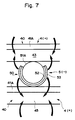
- the strands 40 or 50 forming the electrodes 4 or 5 are only partially covered with the conductive and active layers.
- the grid made up of insulating strands 41 or 51 is absolutely similar to that described above with regard to the embodiment corresponding to FIG. 3A. Is then deposited on the insulating strands 41 or 51 the conductive layers 42 or 52 and active 43 and 53 only on a portion of the perimeter of the strand 41 or 51, so as to leave a free portion 41A or 51A of insulating material.
- the active layers 43 and 53 are separated by the insulating portions 41A and 51A.
- the determination of the amplitude of the portion of the periphery of the strand 41 or 51 which must be covered with the conductive and active layers 42, 52 and 43, 53 depends on the quantity of active material required in the active layer 43 or 53 as well as on the minimum insulating space required between two consecutive grids 4 and 5 in order to completely isolate them and in particular to avoid that, during electrochemical reactions of charge or discharge of the battery, bridges of active material do not form between the active layers electrodes.
- the insulation between the electrodes must also be ensured in the case of slight relative movements of the electrodes between them, due for example to the vibrations of a vehicle on which a battery composed of such elements is installed.
- the method of manufacturing electrodes 4 or 5 differs from what has been described above with regard to electrodes 1 or 3 in that it is necessary to provide masks so that the conductive layers 42.52 and / or active 43.53 don't settle over the entire outer surface of the electrodes and that an insulating face of these remains. These masking operations are known in themselves for other applications. It is also possible to remove a portion of the conductive and active layers already deposited, by chemical or mechanical attack, for example by sanding, of the layers deposited on the surface portion which must remain insulating. According to another alternative embodiment, it is also possible to cover one face of each electrode with an insulating layer. The same methods as described above can be used for woven electrodes.
- FIG. 6B there is an insulating strand 41 or 51 partially covered with a portion of active layer 44 or 54 having conduction properties.
- FIG. 6C shows the variant where the strand 45 or 55 is conductive; in this case it is necessary to deposit a portion of insulating layer 45A or 55A in opposition to the active layer 43 or 53.
- the strand 46, 56 of FIG. 6D having supporting, conductive and active qualities, it is also necessary to deposit a partial insulating layer 46A or 56A.
- FIG. 6B there is an insulating strand 41 or 51 partially covered with a portion of active layer 44 or 54 having conduction properties.
- FIG. 6C shows the variant where the strand 45 or 55 is conductive; in this case it is necessary to deposit a portion of insulating layer 45A or 55A in opposition to the active layer 43 or 53.
- the strand 46, 56 of FIG. 6D having supporting, conductive and active qualities, it is also necessary to deposit a partial insulating layer 46A or 56A.
- FIG. 6E there is a strand of generally rectangular shape 41 or 51 of which only one face is covered with a conductive layer 42, 52 and an active layer 43 or 53, while a similar strand of square shape, as in FIG. 6E also sees two of its lateral faces partially covered with said layers.
- FIG. 6G it can be seen in particular that the active layer 43 or 53 can completely enclose the conductive layer 42 or 52.
- FIG. 6H shows the variant applied to a triangular shape, while FIG. 6I shows it applied to an oval shape : we see here that unlike the variant of FIG. 6G, the conductive layer 42 or 52 may protrude from the active layer 43 or 53. It is understood that the variant forms described here are not exhaustive and that they can also be combined with the variant embodiments of layers mentioned above.
- FIG. 8 shows yet another embodiment of an electrode 6, which may be positive or negative, composed of active strands 60 held by support strands 61.
- the active strands 60 for example of rectangular shape, are formed according to the any of the variant embodiments of the layers described above.
- the support strands 61 are preferably made of an insulating material, their cross section being able to be arbitrary, here rectangular, and preferably comprising notches 62 in order to accommodate and fix the active strands 60.
- an electrode 6 As seen in the figure 8, to constitute an electrode 6, a plurality of supporting strands 61 are spaced apart, parallel to each other, and a plurality of active strands 60 are installed, parallel to each other and perpendicular to the supporting strands 61, each of the active strands 60 being introduced in the aligned notches 62 of the support strands 61, as shown by the arrows in the figure.
- an electrode 6 is obtained, which is sufficiently rigid, also in the form of a grid, electrodes of reverse polarity which can be superimposed since the support strands 61 comprise an additional thickness 63 insulating each electrode 6 with respect to that which it covers.
- FIG. 9A there is an upper electrode, for example a negative electrode 3 or 5 which is superimposed on a lower electrode, for example a positive electrode 1 or 4. Only two electrodes are shown, excluding any grids separation, so as not to overload the figure.
- the two electrodes remain arranged so that their strands are parallel or perpendicular, these strands all having an angle, here 45 °, with respect to to the side walls 72 of the tank 7 of the battery.
- FIG. 9B only half of the electrodes, for example the negatives 3 or 5 are rotated by 45 ° while the other half of the electrodes remains with its strands parallel or perpendicular to the side walls 72.
- the orientation of the strands between the electrodes and with the side walls of the battery tank does not matter and can be arbitrary.
- the positive and negative electrodes as well as the possible separator are made in the form of grids, leaving large spaces between the strands for the circulation of the dielectric liquid.
- the dielectric liquid When the dielectric liquid has passed through all of the electrodes, gradually heating up, as well as any separating grids, it will arrive against the upper cover plate of the battery tank where it will cool and flow along this plate. as well as along the side walls of the battery tank to restart its circuit towards the lower electrode of the battery.
- the ions + supplying or produced by the reaction between the negative and positive electrodes flow through the conductive parts of the strands, whether these conductive parts are formed from a separate layer or are combined with other parts of each strand as explained above. It is then a question of collecting these elementary currents flowing in each strand of the electrodes in order to bring them towards the positive or negative terminals of the battery.
- FIGS. 10A and 11A Means provided for collecting the current on the edges of the positive or negative electrodes are shown in FIGS. 10A and 11A.
- FIG. 10A there is a sectional view portion of a battery enclosed in a tank 7 comprising a bottom wall 70, a cover wall 71 and side walls of which only the side wall 72 is shown.
- the battery itself here consists of six electrodes, three positive electrodes 1 and three negative electrodes 3, separated by separation grids 2.
- Two other separation grids 20 are preferably provided below and above the stacking of electrodes in order to isolate them from the walls 70 and 71 of the tank 7.
- These grids 20 will preferably be slightly different from the grids 2 described until now insofar as conduits located in the plane of said grids are provided to allow the circulation of the dielectric liquid as described above. We can see on the edges of electrodes 1 and 3, conductive areas 19 and 39 prepared as indicated above.
- connection bars 73 For the mode of connection of the electrodes in series, as can be seen schematically represented in FIG. 10B, there are connection bars 73, fully conductive, which are placed between the edges of the electrodes which it is desired to connect.
- this first connection bar 73 comprising a connection shown diagrammatically connecting it to the negative terminal 74 of the battery.
- a second connection bar 73 connects in series the first positive electrode 1 and the second negative electrode 3 and a third connection bar 73 connects in series the second positive electrode 1 and the third negative electrode 3.
- the third positive electrode 1 is connected by a fourth connection bar to the positive terminal 75 of the battery in the same way as seen before for the negative terminal 74. It can be seen in the figure that the separation grids 2 or 20 arranged in the same planes as the bars of connection 73 are stopped at 21 in order to make room for said connection bars.
- the connection bars 73 are preferably slightly thicker than the thickness of a separation grid 2 and have two slightly inclined bearing faces in order to be pressed between the conductive edges of the electrodes and to ensure good electrical contact. .
- FIG. 11A shows a battery similar to the previous one but composed of electrodes which do not require intermediate separation grids.
- the stack of electrodes is preferably taken between two insulating grids 20 in order to isolate it from the walls 70 and 71 of the tank 7 of the battery.
- At least one border of each electrode 4 or 5 is treated in order to reveal a conductive zone 49 or 59 as before. Since the space between the electrodes 4 or 5 is very small, the conductive bars 76 must in this case be sufficiently tapered in order to be able to be inserted between two consecutive electrodes.
- parallel coupling electrodes as shown diagrammatically in FIG.
- connection bars 76 has a connection to one of the terminals 74 or 75 of the battery.
- connection bars 73 or 76 can be seen clearly in FIGS. 12A and 12B; the length of the connection bar corresponds approximately to the longitudinal dimension of the edges of the electrodes, their thickness is a function of the desired clamping effect while their width is chosen so as to have a sufficient contact surface to ensure good contact.
- Similar devices can be provided for the electrodes in woven form, as shown in FIG. 4 or in the form of active strands intertwined with support strands as in FIG. 8. In the latter case, it is also possible to provide conductive parts. on the support strands 61 in order to make connections between the active strands 60 and / or between the electrodes 6, according to the desired coupling mode. We may then not need connection bars as described above.
- connection bars instead of connection bars, it is possible to have connection frames whose dimensions correspond to the dimensions of the sides of the electrodes.
- connection bars 73 or 76 and the terminals 74 and 75 have been shown diagrammatically outside the tank 7; it is also quite possible that these connections are arranged inside the tank 7, for example between the edges of the electrodes and one or the other of the side walls 72.
- the electrodes can be connected in series by crimping or welding the conductive areas of their edges or else contact clips can come to clamp one or two superimposed edges, connection conductors can even be directly welded to said edges.
- the means described can be combined with one another, this on one or more of the side faces of the battery.
- the separation grid 20 is first deposited on the bottom 70, then the connection frame or bar 73 or 76 or the other chosen connection means, then a first electrodes 1 or 3, respectively 4 or 5, then if necessary a separation grid 2 as well as the necessary connection means, then a new electrode of polarity opposite to the previous one and so on until the number of electrodes corresponding to the desired electrical characteristics of the battery are reached. If necessary, the conductive areas still visible after the connections have been made can be coated with an adequate coating in order to protect them from the corrosive effects of the dielectric liquid.
- the operation is completed by depositing the upper separation grid 20 and applying slight compression to the stack of electrodes in order to ensure good electrical contact between the connection elements and to avoid relative displacement of the electrodes during battery usage. If the connections between electrodes are internal to the tank 7, these can be established during the assembly of the electrode stack. Then simply deposit the cover wall 71 and fix it in known manner to the side walls 72, install the terminals 74 and 75 and connect them to the corresponding connections, then fill the battery with its dielectric liquid.
- the elements 70, 71 and 72 of FIGS. 10A and 11A then representing portions of a chassis 7 on which the electrodes and the grids are mounted as described above. Then the chassis 7 is introduced into the battery tank which is then closed as already indicated.
- the electric battery according to the invention comprising electrodes as described above has the advantage compared to the usual known batteries, of being significantly lighter than these since the amount of active material on the electrodes is that necessary only for electro-chemical reactions, the electrical conductance and the mechanical strength of the electrodes being provided by other means. Due to its low mass, such a battery is particularly intended to be carried on a vehicle, although static use is obviously also possible.
- An advantage over other types of reduced mass batteries is that the battery according to the invention can be used in the same way as a conventional battery, without auxiliary heating means for example. Given the horizontal arrangement of the electrodes, they can be housed in a tank of relatively small height but which can have relatively large width and length dimensions as described in application EP-92810450.4.
Landscapes
- Chemical & Material Sciences (AREA)
- Chemical Kinetics & Catalysis (AREA)
- Electrochemistry (AREA)
- General Chemical & Material Sciences (AREA)
- Engineering & Computer Science (AREA)
- Manufacturing & Machinery (AREA)
- Secondary Cells (AREA)
Priority Applications (1)
| Application Number | Priority Date | Filing Date | Title |
|---|---|---|---|
| EP92810984A EP0601263A1 (de) | 1992-12-10 | 1992-12-10 | Batterie und Elektroden für eine solche |
Applications Claiming Priority (1)
| Application Number | Priority Date | Filing Date | Title |
|---|---|---|---|
| EP92810984A EP0601263A1 (de) | 1992-12-10 | 1992-12-10 | Batterie und Elektroden für eine solche |
Publications (1)
| Publication Number | Publication Date |
|---|---|
| EP0601263A1 true EP0601263A1 (de) | 1994-06-15 |
Family
ID=8212050
Family Applications (1)
| Application Number | Title | Priority Date | Filing Date |
|---|---|---|---|
| EP92810984A Withdrawn EP0601263A1 (de) | 1992-12-10 | 1992-12-10 | Batterie und Elektroden für eine solche |
Country Status (1)
| Country | Link |
|---|---|
| EP (1) | EP0601263A1 (de) |
Cited By (1)
| Publication number | Priority date | Publication date | Assignee | Title |
|---|---|---|---|---|
| EP0716465A1 (de) * | 1994-12-06 | 1996-06-12 | Hughes Aircraft Company | Elektrische Vorrichtung mit abwechselenden Schichten aus faserförmigen Elektroden |
Citations (3)
| Publication number | Priority date | Publication date | Assignee | Title |
|---|---|---|---|---|
| US3447967A (en) * | 1967-01-03 | 1969-06-03 | Texas Instruments Inc | Silver-zinc or cadmium type battery with wire mesh screen electrode |
| FR2143212A1 (fr) * | 1971-06-21 | 1973-02-02 | Westinghouse Electric Corp | Procede de fabrication de bandes fibreuses feuilletees |
| EP0097090A1 (de) * | 1982-06-11 | 1983-12-28 | Societe Civile Des Composites Electrolytiques | Anoden aus zusammengesetzten Materialien und Anwendung dieser Anoden in Akkumulatoren |
-
1992
- 1992-12-10 EP EP92810984A patent/EP0601263A1/de not_active Withdrawn
Patent Citations (3)
| Publication number | Priority date | Publication date | Assignee | Title |
|---|---|---|---|---|
| US3447967A (en) * | 1967-01-03 | 1969-06-03 | Texas Instruments Inc | Silver-zinc or cadmium type battery with wire mesh screen electrode |
| FR2143212A1 (fr) * | 1971-06-21 | 1973-02-02 | Westinghouse Electric Corp | Procede de fabrication de bandes fibreuses feuilletees |
| EP0097090A1 (de) * | 1982-06-11 | 1983-12-28 | Societe Civile Des Composites Electrolytiques | Anoden aus zusammengesetzten Materialien und Anwendung dieser Anoden in Akkumulatoren |
Cited By (1)
| Publication number | Priority date | Publication date | Assignee | Title |
|---|---|---|---|---|
| EP0716465A1 (de) * | 1994-12-06 | 1996-06-12 | Hughes Aircraft Company | Elektrische Vorrichtung mit abwechselenden Schichten aus faserförmigen Elektroden |
Similar Documents
| Publication | Publication Date | Title |
|---|---|---|
| CA2051611C (fr) | Procede de preparation d'ensembles collecteurs-electrodes pour generateurs de films minces, ensembles collecteurs- electrodes et generateurs obtenus | |
| FR2960706A1 (fr) | Procede et dispositif pour fabriquer une batterie en couche mince | |
| FR2910721A1 (fr) | Ensemble collecteur de courant-electrode avec des cavites d'expansion pour accumulateur au lithium sous forme de films minces. | |
| EP2073300A2 (de) | Bipolare Batterie mit verbesserter Abdichtung zwischen den Platten | |
| EP3149790A1 (de) | Bleisäurebatterie und verfahren zur herstellung solch einer batterie | |
| FR2461766A1 (fr) | Electrodes avec sorties de courant | |
| FR2489603A1 (fr) | Element accumulateur electrochimique | |
| FR3044659A1 (fr) | Traversee etanche de type verre-metal, utilisation en tant que borne pour accumulateur electrochimique au lithium, procede de realisation associe | |
| CA3179086A1 (fr) | Procede de fabrication d'une batterie a ions de lithium | |
| FR3064116A1 (fr) | Accumulateur deformable | |
| FR3125172A1 (fr) | Pièce de connexion pour élément électrochimique de format prismatique | |
| CA2783080A1 (fr) | Cellule de supercondensateur et module supercapacitif incorporant une pluralite de ces celllules | |
| EP0601263A1 (de) | Batterie und Elektroden für eine solche | |
| EP1964203B1 (de) | Verfahren zur herstellung einer brennstoffzelle mit im festelektrolyt integrierten stromkollektoren | |
| WO2021198843A1 (fr) | Batterie a ions de lithium et son procede de fabrication | |
| EP4162533B1 (de) | Verfahren zur herstellung einer anordnung von solarzellen, die über eine verbindungsstruktur überlappen | |
| EP0538154B1 (de) | Bipolare Elektroden für Bleiakkumulator | |
| EP4016677A1 (de) | Verfahren zur herstellung einer ablaufführung für elektrochemischen reaktor | |
| FR3077681A1 (fr) | Batterie en couches minces | |
| EP4078714A1 (de) | Elektrochemische zelle mit dreidimensionaler elektrodenstruktur | |
| FR2806211A1 (fr) | Ruban faisant office d'ossature pour electrodes a structure fibreuse, plaque d'electrode fabriquee a partir de celui-ci, et leur procede de fabrication | |
| FR2851080A1 (fr) | Batterie comportant plusieurs cellules et procede pour connecter les cellules d'une telle batterie | |
| FR3097370A1 (fr) | Batterie à ions de lithium et son procédé de fabrication | |
| FR3021812A1 (fr) | Accumulateur au plomb-acide, procede de fabrication d'un tel accumulateur et procede de fabrication d'une electrode | |
| FR2616593A1 (fr) | Procede de fabrication de groupes de plaques ou grilles electrodes negatives pour des accumulateurs au plomb, et groupes de plaques ou grilles realises selon ce procede |
Legal Events
| Date | Code | Title | Description |
|---|---|---|---|
| PUAI | Public reference made under article 153(3) epc to a published international application that has entered the european phase |
Free format text: ORIGINAL CODE: 0009012 |
|
| AK | Designated contracting states |
Kind code of ref document: A1 Designated state(s): AT BE CH DE DK ES FR GB GR IE IT LI LU MC NL PT SE |
|
| RBV | Designated contracting states (corrected) |
Designated state(s): AT BE CH DE DK ES FR GB IT LI LU MC NL SE |
|
| 18D | Application deemed to be withdrawn |
Effective date: 19941216 |