EP0601076B1 - Slip control sheeting and articles covered with same - Google Patents
Slip control sheeting and articles covered with same Download PDFInfo
- Publication number
- EP0601076B1 EP0601076B1 EP92919091A EP92919091A EP0601076B1 EP 0601076 B1 EP0601076 B1 EP 0601076B1 EP 92919091 A EP92919091 A EP 92919091A EP 92919091 A EP92919091 A EP 92919091A EP 0601076 B1 EP0601076 B1 EP 0601076B1
- Authority
- EP
- European Patent Office
- Prior art keywords
- sheeting
- bases
- protrusions
- major surface
- further characterized
- Prior art date
- Legal status (The legal status is an assumption and is not a legal conclusion. Google has not performed a legal analysis and makes no representation as to the accuracy of the status listed.)
- Expired - Lifetime
Links
Images



Classifications
-
- B—PERFORMING OPERATIONS; TRANSPORTING
- B32—LAYERED PRODUCTS
- B32B—LAYERED PRODUCTS, i.e. PRODUCTS BUILT-UP OF STRATA OF FLAT OR NON-FLAT, e.g. CELLULAR OR HONEYCOMB, FORM
- B32B3/00—Layered products comprising a layer with external or internal discontinuities or unevennesses, or a layer of non-planar shape; Layered products comprising a layer having particular features of form
- B32B3/26—Layered products comprising a layer with external or internal discontinuities or unevennesses, or a layer of non-planar shape; Layered products comprising a layer having particular features of form characterised by a particular shape of the outline of the cross-section of a continuous layer; characterised by a layer with cavities or internal voids ; characterised by an apertured layer
- B32B3/30—Layered products comprising a layer with external or internal discontinuities or unevennesses, or a layer of non-planar shape; Layered products comprising a layer having particular features of form characterised by a particular shape of the outline of the cross-section of a continuous layer; characterised by a layer with cavities or internal voids ; characterised by an apertured layer characterised by a layer formed with recesses or projections, e.g. hollows, grooves, protuberances, ribs
-
- B—PERFORMING OPERATIONS; TRANSPORTING
- B25—HAND TOOLS; PORTABLE POWER-DRIVEN TOOLS; MANIPULATORS
- B25G—HANDLES FOR HAND IMPLEMENTS
- B25G1/00—Handle constructions
- B25G1/10—Handle constructions characterised by material or shape
-
- B—PERFORMING OPERATIONS; TRANSPORTING
- B29—WORKING OF PLASTICS; WORKING OF SUBSTANCES IN A PLASTIC STATE IN GENERAL
- B29C—SHAPING OR JOINING OF PLASTICS; SHAPING OF MATERIAL IN A PLASTIC STATE, NOT OTHERWISE PROVIDED FOR; AFTER-TREATMENT OF THE SHAPED PRODUCTS, e.g. REPAIRING
- B29C37/00—Component parts, details, accessories or auxiliary operations, not covered by group B29C33/00 or B29C35/00
- B29C37/0053—Moulding articles characterised by the shape of the surface, e.g. ribs, high polish
-
- B—PERFORMING OPERATIONS; TRANSPORTING
- B32—LAYERED PRODUCTS
- B32B—LAYERED PRODUCTS, i.e. PRODUCTS BUILT-UP OF STRATA OF FLAT OR NON-FLAT, e.g. CELLULAR OR HONEYCOMB, FORM
- B32B27/00—Layered products comprising a layer of synthetic resin
- B32B27/40—Layered products comprising a layer of synthetic resin comprising polyurethanes
-
- B—PERFORMING OPERATIONS; TRANSPORTING
- B32—LAYERED PRODUCTS
- B32B—LAYERED PRODUCTS, i.e. PRODUCTS BUILT-UP OF STRATA OF FLAT OR NON-FLAT, e.g. CELLULAR OR HONEYCOMB, FORM
- B32B7/00—Layered products characterised by the relation between layers; Layered products characterised by the relative orientation of features between layers, or by the relative values of a measurable parameter between layers, i.e. products comprising layers having different physical, chemical or physicochemical properties; Layered products characterised by the interconnection of layers
- B32B7/04—Interconnection of layers
- B32B7/05—Interconnection of layers the layers not being connected over the whole surface, e.g. discontinuous connection or patterned connection
-
- B—PERFORMING OPERATIONS; TRANSPORTING
- B32—LAYERED PRODUCTS
- B32B—LAYERED PRODUCTS, i.e. PRODUCTS BUILT-UP OF STRATA OF FLAT OR NON-FLAT, e.g. CELLULAR OR HONEYCOMB, FORM
- B32B7/00—Layered products characterised by the relation between layers; Layered products characterised by the relative orientation of features between layers, or by the relative values of a measurable parameter between layers, i.e. products comprising layers having different physical, chemical or physicochemical properties; Layered products characterised by the interconnection of layers
- B32B7/04—Interconnection of layers
- B32B7/12—Interconnection of layers using interposed adhesives or interposed materials with bonding properties
-
- A—HUMAN NECESSITIES
- A63—SPORTS; GAMES; AMUSEMENTS
- A63B—APPARATUS FOR PHYSICAL TRAINING, GYMNASTICS, SWIMMING, CLIMBING, OR FENCING; BALL GAMES; TRAINING EQUIPMENT
- A63B71/00—Games or sports accessories not covered in groups A63B1/00 - A63B69/00
- A63B71/0054—Features for injury prevention on an apparatus, e.g. shock absorbers
- A63B2071/0063—Shock absorbers
-
- A—HUMAN NECESSITIES
- A63—SPORTS; GAMES; AMUSEMENTS
- A63B—APPARATUS FOR PHYSICAL TRAINING, GYMNASTICS, SWIMMING, CLIMBING, OR FENCING; BALL GAMES; TRAINING EQUIPMENT
- A63B2209/00—Characteristics of used materials
- A63B2209/10—Characteristics of used materials with adhesive type surfaces, i.e. hook and loop-type fastener
-
- A—HUMAN NECESSITIES
- A63—SPORTS; GAMES; AMUSEMENTS
- A63B—APPARATUS FOR PHYSICAL TRAINING, GYMNASTICS, SWIMMING, CLIMBING, OR FENCING; BALL GAMES; TRAINING EQUIPMENT
- A63B5/00—Apparatus for jumping
- A63B5/12—Bolster vaulting apparatus, e.g. horses, bucks, tables
-
- B—PERFORMING OPERATIONS; TRANSPORTING
- B32—LAYERED PRODUCTS
- B32B—LAYERED PRODUCTS, i.e. PRODUCTS BUILT-UP OF STRATA OF FLAT OR NON-FLAT, e.g. CELLULAR OR HONEYCOMB, FORM
- B32B2305/00—Condition, form or state of the layers or laminate
- B32B2305/08—Reinforcements
-
- B—PERFORMING OPERATIONS; TRANSPORTING
- B32—LAYERED PRODUCTS
- B32B—LAYERED PRODUCTS, i.e. PRODUCTS BUILT-UP OF STRATA OF FLAT OR NON-FLAT, e.g. CELLULAR OR HONEYCOMB, FORM
- B32B2307/00—Properties of the layers or laminate
- B32B2307/70—Other properties
- B32B2307/744—Non-slip, anti-slip
-
- B—PERFORMING OPERATIONS; TRANSPORTING
- B32—LAYERED PRODUCTS
- B32B—LAYERED PRODUCTS, i.e. PRODUCTS BUILT-UP OF STRATA OF FLAT OR NON-FLAT, e.g. CELLULAR OR HONEYCOMB, FORM
- B32B2475/00—Frictional elements
-
- Y—GENERAL TAGGING OF NEW TECHNOLOGICAL DEVELOPMENTS; GENERAL TAGGING OF CROSS-SECTIONAL TECHNOLOGIES SPANNING OVER SEVERAL SECTIONS OF THE IPC; TECHNICAL SUBJECTS COVERED BY FORMER USPC CROSS-REFERENCE ART COLLECTIONS [XRACs] AND DIGESTS
- Y10—TECHNICAL SUBJECTS COVERED BY FORMER USPC
- Y10S—TECHNICAL SUBJECTS COVERED BY FORMER USPC CROSS-REFERENCE ART COLLECTIONS [XRACs] AND DIGESTS
- Y10S16/00—Miscellaneous hardware, e.g. bushing, carpet fastener, caster, door closer, panel hanger, attachable or adjunct handle, hinge, window sash balance
- Y10S16/12—Hand grips, preformed and semi-permanent
-
- Y—GENERAL TAGGING OF NEW TECHNOLOGICAL DEVELOPMENTS; GENERAL TAGGING OF CROSS-SECTIONAL TECHNOLOGIES SPANNING OVER SEVERAL SECTIONS OF THE IPC; TECHNICAL SUBJECTS COVERED BY FORMER USPC CROSS-REFERENCE ART COLLECTIONS [XRACs] AND DIGESTS
- Y10—TECHNICAL SUBJECTS COVERED BY FORMER USPC
- Y10T—TECHNICAL SUBJECTS COVERED BY FORMER US CLASSIFICATION
- Y10T428/00—Stock material or miscellaneous articles
- Y10T428/23—Sheet including cover or casing
- Y10T428/239—Complete cover or casing
-
- Y—GENERAL TAGGING OF NEW TECHNOLOGICAL DEVELOPMENTS; GENERAL TAGGING OF CROSS-SECTIONAL TECHNOLOGIES SPANNING OVER SEVERAL SECTIONS OF THE IPC; TECHNICAL SUBJECTS COVERED BY FORMER USPC CROSS-REFERENCE ART COLLECTIONS [XRACs] AND DIGESTS
- Y10—TECHNICAL SUBJECTS COVERED BY FORMER USPC
- Y10T—TECHNICAL SUBJECTS COVERED BY FORMER US CLASSIFICATION
- Y10T428/00—Stock material or miscellaneous articles
- Y10T428/24—Structurally defined web or sheet [e.g., overall dimension, etc.]
- Y10T428/24174—Structurally defined web or sheet [e.g., overall dimension, etc.] including sheet or component perpendicular to plane of web or sheet
- Y10T428/24182—Inward from edge of web or sheet
-
- Y—GENERAL TAGGING OF NEW TECHNOLOGICAL DEVELOPMENTS; GENERAL TAGGING OF CROSS-SECTIONAL TECHNOLOGIES SPANNING OVER SEVERAL SECTIONS OF THE IPC; TECHNICAL SUBJECTS COVERED BY FORMER USPC CROSS-REFERENCE ART COLLECTIONS [XRACs] AND DIGESTS
- Y10—TECHNICAL SUBJECTS COVERED BY FORMER USPC
- Y10T—TECHNICAL SUBJECTS COVERED BY FORMER US CLASSIFICATION
- Y10T428/00—Stock material or miscellaneous articles
- Y10T428/24—Structurally defined web or sheet [e.g., overall dimension, etc.]
- Y10T428/24355—Continuous and nonuniform or irregular surface on layer or component [e.g., roofing, etc.]
-
- Y—GENERAL TAGGING OF NEW TECHNOLOGICAL DEVELOPMENTS; GENERAL TAGGING OF CROSS-SECTIONAL TECHNOLOGIES SPANNING OVER SEVERAL SECTIONS OF THE IPC; TECHNICAL SUBJECTS COVERED BY FORMER USPC CROSS-REFERENCE ART COLLECTIONS [XRACs] AND DIGESTS
- Y10—TECHNICAL SUBJECTS COVERED BY FORMER USPC
- Y10T—TECHNICAL SUBJECTS COVERED BY FORMER US CLASSIFICATION
- Y10T428/00—Stock material or miscellaneous articles
- Y10T428/24—Structurally defined web or sheet [e.g., overall dimension, etc.]
- Y10T428/24479—Structurally defined web or sheet [e.g., overall dimension, etc.] including variation in thickness
- Y10T428/2457—Parallel ribs and/or grooves
-
- Y—GENERAL TAGGING OF NEW TECHNOLOGICAL DEVELOPMENTS; GENERAL TAGGING OF CROSS-SECTIONAL TECHNOLOGIES SPANNING OVER SEVERAL SECTIONS OF THE IPC; TECHNICAL SUBJECTS COVERED BY FORMER USPC CROSS-REFERENCE ART COLLECTIONS [XRACs] AND DIGESTS
- Y10—TECHNICAL SUBJECTS COVERED BY FORMER USPC
- Y10T—TECHNICAL SUBJECTS COVERED BY FORMER US CLASSIFICATION
- Y10T428/00—Stock material or miscellaneous articles
- Y10T428/24—Structurally defined web or sheet [e.g., overall dimension, etc.]
- Y10T428/24479—Structurally defined web or sheet [e.g., overall dimension, etc.] including variation in thickness
- Y10T428/24612—Composite web or sheet
-
- Y—GENERAL TAGGING OF NEW TECHNOLOGICAL DEVELOPMENTS; GENERAL TAGGING OF CROSS-SECTIONAL TECHNOLOGIES SPANNING OVER SEVERAL SECTIONS OF THE IPC; TECHNICAL SUBJECTS COVERED BY FORMER USPC CROSS-REFERENCE ART COLLECTIONS [XRACs] AND DIGESTS
- Y10—TECHNICAL SUBJECTS COVERED BY FORMER USPC
- Y10T—TECHNICAL SUBJECTS COVERED BY FORMER US CLASSIFICATION
- Y10T428/00—Stock material or miscellaneous articles
- Y10T428/24—Structurally defined web or sheet [e.g., overall dimension, etc.]
- Y10T428/24942—Structurally defined web or sheet [e.g., overall dimension, etc.] including components having same physical characteristic in differing degree
-
- Y—GENERAL TAGGING OF NEW TECHNOLOGICAL DEVELOPMENTS; GENERAL TAGGING OF CROSS-SECTIONAL TECHNOLOGIES SPANNING OVER SEVERAL SECTIONS OF THE IPC; TECHNICAL SUBJECTS COVERED BY FORMER USPC CROSS-REFERENCE ART COLLECTIONS [XRACs] AND DIGESTS
- Y10—TECHNICAL SUBJECTS COVERED BY FORMER USPC
- Y10T—TECHNICAL SUBJECTS COVERED BY FORMER US CLASSIFICATION
- Y10T428/00—Stock material or miscellaneous articles
- Y10T428/28—Web or sheet containing structurally defined element or component and having an adhesive outermost layer
- Y10T428/2813—Heat or solvent activated or sealable
-
- Y—GENERAL TAGGING OF NEW TECHNOLOGICAL DEVELOPMENTS; GENERAL TAGGING OF CROSS-SECTIONAL TECHNOLOGIES SPANNING OVER SEVERAL SECTIONS OF THE IPC; TECHNICAL SUBJECTS COVERED BY FORMER USPC CROSS-REFERENCE ART COLLECTIONS [XRACs] AND DIGESTS
- Y10—TECHNICAL SUBJECTS COVERED BY FORMER USPC
- Y10T—TECHNICAL SUBJECTS COVERED BY FORMER US CLASSIFICATION
- Y10T428/00—Stock material or miscellaneous articles
- Y10T428/28—Web or sheet containing structurally defined element or component and having an adhesive outermost layer
- Y10T428/2848—Three or more layers
-
- Y—GENERAL TAGGING OF NEW TECHNOLOGICAL DEVELOPMENTS; GENERAL TAGGING OF CROSS-SECTIONAL TECHNOLOGIES SPANNING OVER SEVERAL SECTIONS OF THE IPC; TECHNICAL SUBJECTS COVERED BY FORMER USPC CROSS-REFERENCE ART COLLECTIONS [XRACs] AND DIGESTS
- Y10—TECHNICAL SUBJECTS COVERED BY FORMER USPC
- Y10T—TECHNICAL SUBJECTS COVERED BY FORMER US CLASSIFICATION
- Y10T74/00—Machine element or mechanism
- Y10T74/20—Control lever and linkage systems
- Y10T74/20576—Elements
- Y10T74/20732—Handles
- Y10T74/2078—Handle bars
- Y10T74/20828—Handholds and grips
Definitions
- the present invention relates to slip control sheetings with a structured surface and articles, e.g., gymnastic apparatuses and handles of tools, mallets, racquets, baseball bats, golf clubs, and sport sticks, with such sheeting applied thereto.
- a structured surface and articles e.g., gymnastic apparatuses and handles of tools, mallets, racquets, baseball bats, golf clubs, and sport sticks, with such sheeting applied thereto.
- the handles of many tools, mallets, racquets, golf clubs and sport sticks have leather grips
- some of the same problems associated with the use of leather covers for gymnastic apparatuses are also encountered during use of these handles.
- the leather grips can be slippery when new.
- the leather grips tend to become impregnated with perspiration during use of the grips, causing the grips to become more slippery with increasing use.
- this can result in reduced gripping of the handle and a consequent drop in safety and performance potential.
- users of leather gripped handles often apply chalk or tacky substances to the grips to improve their gripping.
- U.S. Patent No. 3,585,101 discloses a material comprising a film having a knurled pattern, e.g., a series of ridges, on one surface and an adhesive layer on the opposite surface.
- U.S. Patent No. 4,488,918 discloses a plastic film having a non-slip surface comprising spaced random patterns of rigid peaks and ridges formed of a second thermoplastic layer coextruded with and bonded to the plastic film.
- European Patent Application No. 81830005.5, Publication No. 033,301 discloses handle coverings for tennis racquets and the like which comprise sleeves with relief patterns for a good grip.
- U.K. Patent No. 2,057,894 discloses a tape for grips of game and sports appliances, e.g., racquets.
- Document FR-A-2,125,305 discloses anti-slip garments comprising a textile material, typically rough, that has braking elements protruding therefrom.
- the braking elements can be in the form of cylindrical or conical projections or truncated cones, pyramids, or fractions of a sphere.
- the braking elements can be inserted in the sports garment in the form of strips or pieces or can be permanently placed in certain spots on the garment by, for example, sewing, riveting, glueing, or vulcanization operations.
- Document DE-A-28 07 658 discloses a sports glove, especially for use by goalkeepers, comprising an elastic lining material and a multi-level profile of nub-shaped or otherwise designed elevations protruding from a base plane of the elastic lining material as well as circular or rectangular recesses provided in the base plane.
- the multi-level profile typically takes the form of at least three levels lying in different planes.
- Document DE-A-32 03 023 discloses a sports glove, especially for use by goalkeepers, comprising correspondingly shaped inner and outer palm linings, wherein the inner palm lining is provided on its outside with a contact-fastening layer that is adapted to be detachably mated with a fleece layer provided on the inside of the outer palm lining.
- a slip control sheeting comprising a backing having a first and a second major surface and an array of protrusions on said first major surface, characterized in that said protrusions have a height of between 75 and 750 ⁇ m, said protrusions comprise at least one of pyramids with polygonal bases or pyramidal frustums with polygonal bases, said array is defined in part by a pattern of intersecting sets of parallel grooves formed in said first major surface, which grooves define major axes of said sheeting, and at least one of the following:
- the sheeting may be applied to articles which are adapted for interaction with hands or feet, such as gymnastic stations particularly for example a pommel horse, athletic equipment, tools and mallets.
- articles to which sheetings of the invention have been applied exhibit more uniform and more consistent slip control properties, thereby enhancing their safe, convenient, and effective use.
- articles such as gymnastic equipment covered with sheetings of the invention exhibit improved durability, retention of more uniform slip properties over entire service life time, and more consistent slip properties over the entire apparatus.
- Sheetings of the invention may be applied to new or older gymnastic equipment.
- Figures 1-3 are idealized and are not to scale.
- Figure 1 illustrates an illustrative slip control sheeting of the invention 10 comprising backing 12 having first major surface 14 and second major surface 16 and optional adhesive layer 18 on second major surface 16.
- First major surface 14 and second major surface 16 are typically generally planar.
- Adhesive layer 18 will typically be covered by optional release liner 20 during shipping and storage of sheeting 10.
- First major surface 14 bears an array (i.e., an orderly arrangement such as a regularly repeating pattern) of protrusions 22 thereon.
- Protrusions 22 may be discrete elements laminated to backing 12 or may be integral parts of backing 12, i.e., backing 12 may be structured in the form of protrusions 22.
- protrusions 22 comprise pyramidal protrusions, i.e., pyramids with polygonal bases or pyramidal frustums with polygonal bases.
- Each polygonal base is disposed on first major surface 14 of backing 12 and is defined by a plurality of line segments which lie in or on the plane of first major surface 14.
- the polygonal bases of protrusions 22 are preferably selected from the group consisting of triangular bases, quadrilateral bases, pentagonal bases, hexagonal bases, heptagonal bases, octagonal bases, nonagonal bases and decagonal bases.
- protrusions 22 are triangular pyramids, i.e., three-sided pyramids having triangular bases.
- the polygonal bases of protrusions 22 are typically immediately adjacent one another such that there is no land separating the polygonal bases.
- the line segments defining the sides of the polygonal base of each pyramidal protrusion are preferably relatively equal in length, but need not be. By relatively equal, it is meant that the length of the shortest line segment is equal to at least about 50 percent of the length of the longest line segment. Most preferably, the line segments defining the sides of the polygonal base of each pyramidal protrusion are equal in length.
- Each line segment is typically between 5 and 75 mils (125 and 1,875 ⁇ m), but preferably is between 5 and 30 mils (125 and 750 ⁇ m), and most preferably between 10 and 20 mils (250 and 500 ⁇ m), in length.
- a pattern of three intersecting sets of parallel v-shaped grooves yields the structured surface.
- the apexes of each set of grooves are identified as a, b, and c.
- the base of each individual protrusion 22 is defined by one groove of each of the three sets.
- the three sides of the base of each three-sided pyramid are typically relatively equal in length. This can be controlled by selection of the intersection angles between the three sets of grooves, i.e., angles alpha, beta, and gamma.
- Each side of the base of a pyramidal protrusion and the peak of that protrusion defines a plane, referred to herein as a face of the protrusion.
- the faces of each protrusion are preferably relatively equal in area.
- sheeting shown in Figure 2 has three major axes.
- sheetings of the invention are characterized as having directional gripping characteristics.
- each frustum typically has a planar top or upper surface which is parallel to its base, although it is contemplated that the planar top or upper surface of the frustum can be inclined at an angle relative to the frustum's base. Further, the tops or upper surfaces of the frustums are not necessarily planar.
- a sheeting of the invention comprises pyramids or cones, it is typically preferred, but not essential, that the peak of the pyramid or cone be centered over the geometric center of the base of the pyramid or cone. If a sheeting of the invention comprises pyramidal or conical frustums, it is preferred, but not essential, that the planar tops of the frustums have geometric centers which are centered over the geometric centers of their respective bases. In some instances, if the protrusions of a sheeting have peaks or planar tops which are "horizontally offset" from their respective bases, the sheeting may have directional gripping characteristics as a result. Sheetings having directional gripping characteristics would likely be considered desirable in many envisioned applications.
- the protrusions are typically between 3 mils and 21 mils (75 and 525 ⁇ m), preferably between 5 mils and 9 mils (125 and 225 ⁇ m), and most preferably 7 mils (175 ⁇ m), in height.
- sheetings of the invention can comprise protrusions up to 30 mils (750 ⁇ m) in height, although such sheetings may tend to be abrasive to one's skin.
- the height h of a protrusion refers to the length of the shortest possible line segment extending from the protrusion's peak P to its base.
- the protrusion's peak is defined to be the highest point of the protrusion, i.e., the point of the protrusion located furthest from the plane in which first major surface 14 lies.
- the shape of a protrusion is characterized by its aspect ratio, which is defined as the ratio of the protrusion's height h to its equivalent base diameter D eq .
- the equivalent base diameter D eq is simply the diameter of the circle.
- the equivalent base diameter D eq is defined as the diameter of a hypothetical circle having the same area as the base. It is believed that the invention can be practiced satisfactorily if the protrusions have an aspect ratio which is from about 0.1 to about 5. Most preferably, the aspect ratio for pyramidal protrusions is from about 0.3 to about 0.6.
- Backing 12 typically comprises a polymeric film selected from, for example, the group consisting of polyvinyls, polyurethanes, polyesters, e.g., polyethylene terephthalate, polyacrylics, polycarbonates, polyolefins, and mixtures thereof.
- Polyurethanes are presently preferred because they typically yield slip control sheetings which offer an optimum combination of high toughness and durability coupled with high softness and flexibility.
- Polyacrylics typically yield slip control sheetings that are relatively rigid.
- the backing can be a solid film or a foamed film.
- the sheeting of the invention can include optional release liner 20 and optional adhesive layer 18, adhesive layer 18 typically comprising an adhesive selected to provide a strong bond to the substrate article to which the resultant sheeting is to be applied.
- adhesive layer 18 typically comprising an adhesive selected to provide a strong bond to the substrate article to which the resultant sheeting is to be applied.
- heat-activated adhesives, pressure-sensitive adhesives, and mixtures thereof can be used.
- An illustrative example of a useful adhesive is Adhesive Transfer Tape 950 from Minnesota Mining and Manufacturing Company. Many suitable epoxy, urethane, and acrylic adhesives are commercially available.
- sheetings of the invention need not include adhesive layer 18 or release liner 20.
- the sheeting of the invention can alternatively comprise a reinforcing web, e.g., a sheet of fabric, or a mechanical fastening component for fastening the backing to a substrate.
- sheetings of the invention can include combinations of two or more of the above. Sheetings having a reinforcing web are considered especially useful when it is desired to sew the sheeting to a substrate.
- the sheeting comprises a reinforcing web
- backing 12 will in some instances be sufficiently thick to embed the web therein.
- the web can merely be suitably secured to second major surface 16 of backing 12.
- Embedded webs can impart increased tear resistance and tensile strength, enabling the slip control sheeting to be attached to a substrate via sewing more effectively.
- the web in cases where the web protrudes from second major surface 16 of backing 12, the web can provide an increased surface area, thereby improving the bond to an adhesive layer or substrate.
- the sheeting of the invention comprises a mechanical fastening component for fastening the backing to a substrate
- the mechanical fastening component can take the form of a plurality of hooks or a plurality of loops disposed on second major surface 16, the hooks or loops constituting part of a hook and loop type fastening system, e.g., a VELCRO Brand fastener.
- the mechanical fastening component would take the form of a structured surface which includes a plurality of tapered elements.
- Each tapered element can comprise a side which is inclined relative to the plane of the structured surface at an angle sufficient to form a taper.
- each tapered element is adapted to mate through a frictional or torsional force of adherence with at least one corresponding element of a complementarily structured surface of a substrate.
- An example of a mechanical fastening component which utilizes a frictional force of adherence is disclosed in U.S. Patent No. 4,875,259 (Appeldorn).
- a torsional force of adherence can be effected if at least one of the tapered elements of the structured surface of the sheeting or the complementarily structured surface of the substrate can be axially bent or torsionally flexed relative to its relaxed, unfastened position. This permits the sheeting to be fastened with a substrate in a random alignment.
- the protrusions of the sheeting may be made of a first, relatively hard and highly durable material, and the backing may be made of a relatively more flexible material.
- the material of the protrusions can comprise an abrasive or other fillers.
- the protrusions preferably comprise a substantially solid material, it is contemplated that the protrusions can be made of foam.
- all or a portion of each protrusion can be filled with a fluid, e.g., a gas such as air or nitrogen. If a gas were used, the pressure of the gas within each protrusion would have to be selected to provide the protrusions with the desired amount of compressibility.
- Properly constructed sheetings of the invention generally exhibit a combination of high durability and friction due to the coupling of hard protrusions (e.g., polycarbonate), which are typically substantially incompressible and non-collapsible, with a more conformable, flexible backing material (e.g., polyurethane) that results in a more cushioned impact during use.
- a sheeting of the invention is sufficiently flexible to be wound about itself on a 1 inch (2.54 cm) diameter mandrel.
- sheetings of the invention can be made using techniques which are somewhat similar to those used to make cube-corner retroreflective sheetings. It will be understood, however, that a sheeting of the invention can be made of a substantially non-retroreflective material such as a substantially opaque or translucent material if desired, and can even be made in a variety of colors if desired.
- sheeting 10 can be made such that it will retroreflect less than about 10 percent of a beam of electromagnetic radiation which is incident at any angle to second major surface 16, the electromagnetic radiation having any wavelength within the visible light or infrared radiation regions, i.e., wavelengths ranging from about 0.39 microns to about 1,000 microns.
- sheeting 10 can have a structure similar to retroreflective sheetings, but need not be retroreflective. This means that sheeting 10 can be made of less expensive materials because optical performance is not a concern. Further, sheeting 10 need not necessarily be manufactured in as precise a manner as retroreflective sheetings of the prior art since optical performance is not needed.
- a sheeting of the invention may be formed by cutting a series of v-shaped grooves into a solid sheeting, molding a sheeting with the desired protrusions thereon, or molding protrusions and then applying them to a desired backing sheet.
- Many of the techniques used for fabricating cube-corner retroreflective sheeting may be used to form slip control sheets of the invention, with the important advantage that the optical properties critical to retroreflective sheetings are not necessary for sheets of the invention.
- U.S. Patent No. 4,576,850 (Martens) discloses a process for replicating microstructured surfaces that may be used in making sheetings of the invention.
- U.S. Patent No. 3,689,346 also discloses a method comprising applying a hardenable molding material over a mold having a multiplicity of cube-corner formations therein.
- FIG. 1 illustrates vaulting horse 100 with body 102 on legs 104.
- a slip control sheeting 10 has been applied to surface 106.
- Desired flexibility, elasticity, and conformability of the sheeting is dependent in part upon the station to which it is to be applied.
- the sheeting should be somewhat elastic and conformable so as to give or compress under pressure of the gymnasts' hands and/or feet.
- the parallel bars, uneven bars, and high bar do not compress in this fashion but they typically flex. Accordingly, a sheeting of the invention for use thereon should be flexible.
- Sheetings of the invention may be applied to the handles of such athletic equipment as baseball bats, golf clubs, and tennis, racquetball, squash, and badminton racquets. If desired, sheetings of the invention may be applied to the gripping surfaces of gloves to improve the grip obtained with conformable surfaces, e.g., rubber or foam-covered bats or water ski handles. Sheetings of the invention may be applied to the handles of mallets or tools such as hammers, pliers, wire cutters, screw drivers, wrenches, etc.
- Sheetings of the invention may be used with bars provided in rest rooms for handicapped persons or railings in stairwells as they are a convenient means for providing secure, effective slip control and readily cleaned or washed surfaces. They may also be applied to such articles as diving boards and the areas around swimming pools. Further, sheetings of the invention can be applied to the support surfaces of eye glasses, especially the support surfaces which come in contact with the wearer's nose.
- a slip control sheeting of the invention can be secured to a surface of an article which is adapted for interaction with hands or feet to impart favorable slip control properties to the surface. It is contemplated that such articles would include articles adapted to be manipulated by one's hand, such as hammers, as well as articles which provide secure footing, such as shower mats.
- the protrusions were three-sided pyramids about 7 mils (175 ⁇ m) in height formed from a master made by cutting v-shaped grooves, with angles alpha and beta equal to about 55° and angle gamma equal to about 70°.
- the grooves in set a were spaced about 14 mils (355 ⁇ m) apart
- the grooves in set b were spaced about 16 mils (410 ⁇ m) apart
- those in set c were spaced about 16 mils (410 ⁇ m) apart.
- Each gymnast wore a reflective target on the outside of his right hand near the proximal head of the fifth metacarpal.
- Digital analysis was performed using the Peak Performance Video and Analog Motion Measurement System from Peak Performance Technologies, Inc., Englewood, Colorado, U.S.A.
- the video digitizing/playback system employed a Panasonic AG-7300 video cassette recorder, a Sony Trinitron monitor, and an IBM-compatible computer. Coordinate data was smoothed using a low-pass, fourth order, zero lag Butterworth digital filter with a cutoff frequency of 5 Hertz. Smoothed coordinate data were used to calculate displacement and velocity parameters.
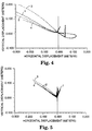
- Table I contains the displacement results from Horse A. This information is shown graphically in Figure 4.
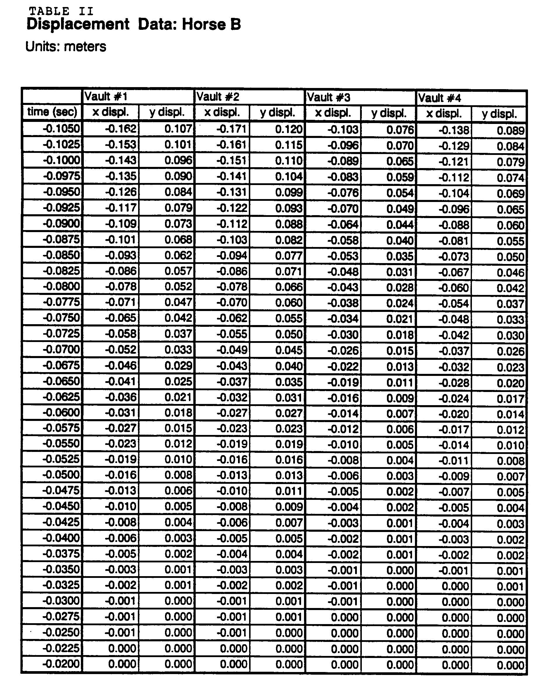
- Table II contains the displacement results from Horse B. This information is shown graphically in Figure 5.
- Table III contains the resultant velocities for vaults 1 and 2 on Horse A.
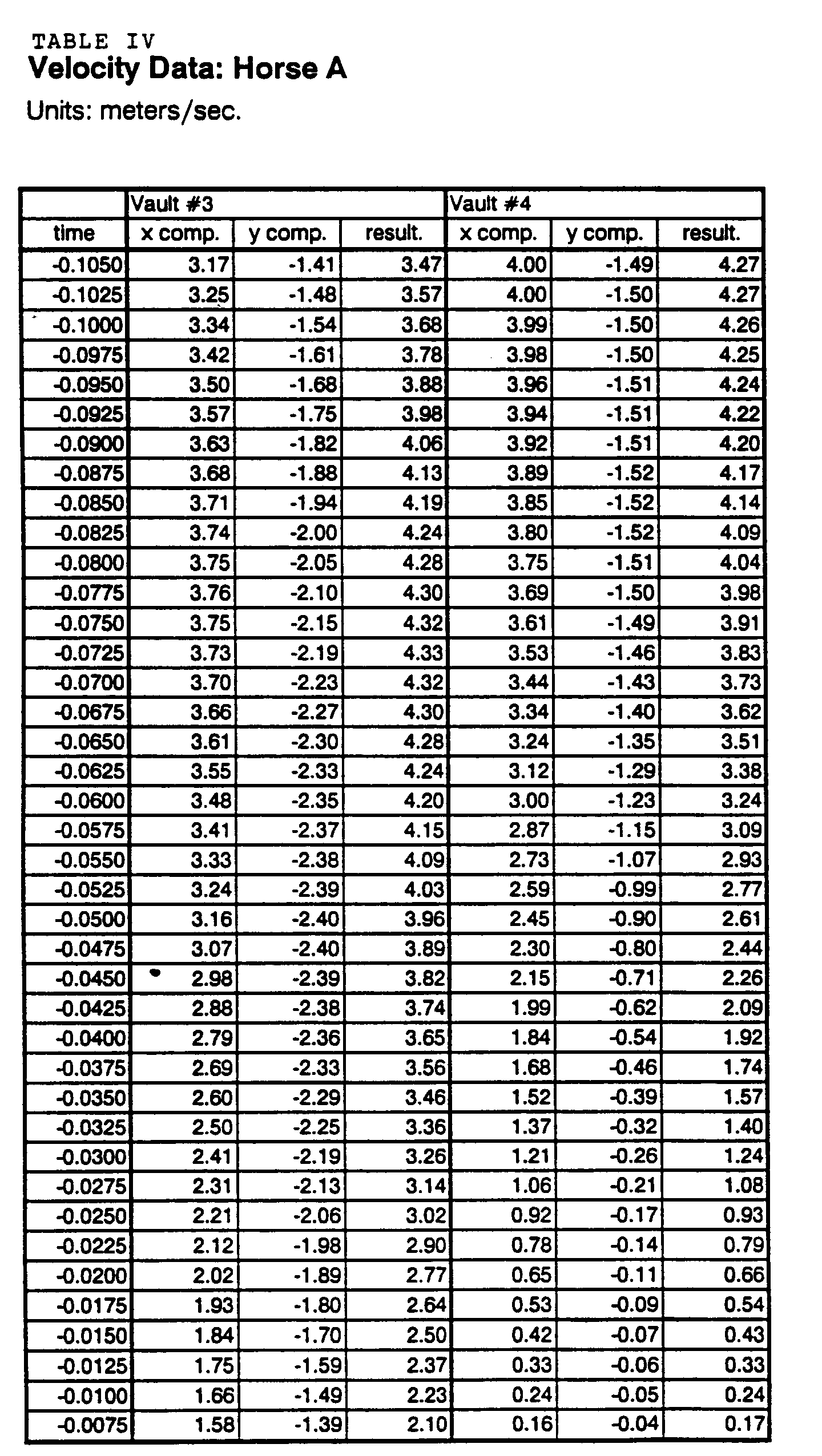
- Table IV contains the resultant velocities for vaults 3 and 4 on Horse A. This information is shown graphically in Figure 6.
- Table V contains the resultant velocities for vaults 1 and 2 on Horse B.
- Table VI contains the resultant velocities for vaults 3 and 4 on Horse B. This information is shown graphically in Figure 7.
- Figure 4 shows the path of the target over time for each of the vaults by both gymnasts on Horse A.
- Figure 5 shows the path of the target over time for each vault by both gymnasts on Horse B.
- curves 1 and 3 represent the vaults by the first gymnast and curves 2 and 4 represent the vaults by the second gymnast.
- Figure 6 is a graphical illustration of the resultant velocities of the gymnasts in the vaults shown in Figure 4 and Figure 7 is a corresponding graphical illustration of the resultant velocities of the gymnasts in the vaults shown in Figure 5.
- "Resultant velocity” is the magnitude of the vector sum of the vertical and horizontal velocities as calculated from the tables.
Landscapes
- Engineering & Computer Science (AREA)
- Mechanical Engineering (AREA)
- Laminated Bodies (AREA)
- Manufacture Of Macromolecular Shaped Articles (AREA)
- Golf Clubs (AREA)
- Lubricants (AREA)
Abstract
Description
- The present invention relates to slip control sheetings with a structured surface and articles, e.g., gymnastic apparatuses and handles of tools, mallets, racquets, baseball bats, golf clubs, and sport sticks, with such sheeting applied thereto.
- Gymnastic apparatuses such as pommel horses are typically covered with leather covers. Because such covers are usually somewhat slippery when new, they are typically conditioned by roughening with scouring pads, wire brushes, knives, etc. Scouring is typically done by hand with a circular motion resulting in a visible pattern of swirls on the surface. Conditioning in this fashion entails cutting and gouging the surface of the cover, tending to result in shortened life of the cover, making it necessary to have the apparatus recovered periodically.
- Gymnasts frequently apply chalk to their hands when practicing and during performances. This chalk builds up on the cover of the apparatus, filling in the texture and leaving a smooth, somewhat hard surface that must be brushed or sanded to remove the chalk. Because of the pattern of swirls and rough texture of a hand-conditioned cover, it is difficult to remove chalk as desired. In addition to chalk, such substances as KARO Brand Corn Syrup, pine tar, and spray adhesive are sometimes used by gymnasts to improve their grip to conventional covers.
- In light of these conditions, conventional gymnastic apparatus covers, which cost several hundred dollars, may wear out after relatively short periods, presenting substantial costs to schools and other gymnasium operators. Also, surface conditioning practices and uneven wear may impart substantially non-uniform characteristics to a cover, presenting potentially unsafe conditions to a gymnast as seemingly similar portions of a cover may exhibit substantially different properties. In some cases, falls may lead to serious injuries such as broken bones and paralysis. The need for higher grip surfaces for gymnastics apparatuses has been known for a long time.
- Because the handles of many tools, mallets, racquets, golf clubs and sport sticks have leather grips, some of the same problems associated with the use of leather covers for gymnastic apparatuses are also encountered during use of these handles. For example, the leather grips can be slippery when new. Perhaps more importantly, the leather grips tend to become impregnated with perspiration during use of the grips, causing the grips to become more slippery with increasing use. Of course, this can result in reduced gripping of the handle and a consequent drop in safety and performance potential. For this reason, users of leather gripped handles often apply chalk or tacky substances to the grips to improve their gripping. The repeated cycles of impregnation of the leather grip with perspiration and subsequent drying in the periods when the grip is not being used, combined with natural aging, result in rapid drying of the leather grip, which loses its softness and must be replaced. Further, if chalk or tacky substances are applied to the leather grip, there may be a tendency for these materials to build up on the grip and further reduce the life of the grip.
- In light of the above drawbacks associated with the use of leather grips, some people have substituted rubber or plastic grips for the leather grips. These substitute grips have some advantages over leather grips since they tend to resist perspiration impregnation, can be easier to dry, may not age as quickly, and may be washable. However, the need for better gripping characteristics has remained.
- U.S. Patent No. 3,585,101 (Stratton et al.) discloses a material comprising a film having a knurled pattern, e.g., a series of ridges, on one surface and an adhesive layer on the opposite surface. U.S. Patent No. 4,488,918 (Jofs) discloses a plastic film having a non-slip surface comprising spaced random patterns of rigid peaks and ridges formed of a second thermoplastic layer coextruded with and bonded to the plastic film. European Patent Application No. 81830005.5, Publication No. 033,301 (Gibello) discloses handle coverings for tennis racquets and the like which comprise sleeves with relief patterns for a good grip. U.K. Patent No. 2,057,894 (Sasaki) discloses a tape for grips of game and sports appliances, e.g., racquets.
- Document FR-A-2,125,305 discloses anti-slip garments comprising a textile material, typically rough, that has braking elements protruding therefrom. The braking elements can be in the form of cylindrical or conical projections or truncated cones, pyramids, or fractions of a sphere. The braking elements can be inserted in the sports garment in the form of strips or pieces or can be permanently placed in certain spots on the garment by, for example, sewing, riveting, glueing, or vulcanization operations. Document DE-A-28 07 658 discloses a sports glove, especially for use by goalkeepers, comprising an elastic lining material and a multi-level profile of nub-shaped or otherwise designed elevations protruding from a base plane of the elastic lining material as well as circular or rectangular recesses provided in the base plane. The multi-level profile typically takes the form of at least three levels lying in different planes. Document DE-A-32 03 023 discloses a sports glove, especially for use by goalkeepers, comprising correspondingly shaped inner and outer palm linings, wherein the inner palm lining is provided on its outside with a contact-fastening layer that is adapted to be detachably mated with a fleece layer provided on the inside of the outer palm lining.
- According to the present invention there is provided a slip control sheeting comprising a backing having a first and a second major surface and an array of protrusions on said first major surface, characterized in that said protrusions have a height of between 75 and 750 µm, said protrusions comprise at least one of pyramids with polygonal bases or pyramidal frustums with polygonal bases, said array is defined in part by a pattern of intersecting sets of parallel grooves formed in said first major surface, which grooves define major axes of said sheeting, and at least one of the following:
- a) said sheeting comprises at least one of a layer of adhesive on said second major surface, a reinforcing web, or a mechanical fastening component for fastening said backing to a substrate; and
- b) said sheeting retroreflects less than 10 percent of a beam of electromagnetic radiation which is incident at any angle to said second major surface, the electromagnetic radiation having any wavelength from 0.39 µm to 1,000 µm.
- Optional features of the invention are set out in
claims 2 to 10 below. - The sheeting may be applied to articles which are adapted for interaction with hands or feet, such as gymnastic stations particularly for example a pommel horse, athletic equipment, tools and mallets.
- Among the many advantages that can be provided by this invention are that articles to which sheetings of the invention have been applied exhibit more uniform and more consistent slip control properties, thereby enhancing their safe, convenient, and effective use. Also, articles such as gymnastic equipment covered with sheetings of the invention exhibit improved durability, retention of more uniform slip properties over entire service life time, and more consistent slip properties over the entire apparatus. Sheetings of the invention may be applied to new or older gymnastic equipment.
- The invention will be further explained with reference to the drawing, wherein:
- Figure 1 is a cross-section of a portion of an illustrative slip control sheeting of the invention;
- Figure 2 is a plan view of a portion of the first major surface of an illustrative slip control sheeting of the invention;
- Figure 3 is a side view of a gymnastic station to which a sheeting of the invention has been applied;
- Figure 4 is a graphical illustration of the paths of motion of the hands of illustrative gymnasts performing handspring full vaults using a horse with a conventional cover;
- Figure 5 is a graphical illustration of the paths of motion of the hands of illustrative gymnasts performing handspring full vaults using a horse covered with an illustrative slip control sheeting of the invention;
- Figure 6 is a graphical illustration of the resultant speed of the gymnasts in the vaults shown in Figure 4; and
- Figure 7 is a graphical illustration of the resultant speed of the gymnasts in the vaults shown in Figure 5.
- Figures 1-3 are idealized and are not to scale.
- Figure 1 illustrates an illustrative slip control sheeting of the
invention 10 comprisingbacking 12 having firstmajor surface 14 and secondmajor surface 16 and optionaladhesive layer 18 on secondmajor surface 16. Firstmajor surface 14 and secondmajor surface 16 are typically generally planar.Adhesive layer 18 will typically be covered byoptional release liner 20 during shipping and storage ofsheeting 10. Firstmajor surface 14 bears an array (i.e., an orderly arrangement such as a regularly repeating pattern) ofprotrusions 22 thereon.Protrusions 22 may be discrete elements laminated to backing 12 or may be integral parts of backing 12, i.e., backing 12 may be structured in the form ofprotrusions 22. - In a first embodiment of the invention,
protrusions 22 comprise pyramidal protrusions, i.e., pyramids with polygonal bases or pyramidal frustums with polygonal bases. Each polygonal base is disposed on firstmajor surface 14 ofbacking 12 and is defined by a plurality of line segments which lie in or on the plane of firstmajor surface 14. - The polygonal bases of
protrusions 22 are preferably selected from the group consisting of triangular bases, quadrilateral bases, pentagonal bases, hexagonal bases, heptagonal bases, octagonal bases, nonagonal bases and decagonal bases. In a most preferred form of the first embodiment, as shown in Figures 1 and 2,protrusions 22 are triangular pyramids, i.e., three-sided pyramids having triangular bases. As shown in Figure 2, the polygonal bases ofprotrusions 22 are typically immediately adjacent one another such that there is no land separating the polygonal bases. - The line segments defining the sides of the polygonal base of each pyramidal protrusion are preferably relatively equal in length, but need not be. By relatively equal, it is meant that the length of the shortest line segment is equal to at least about 50 percent of the length of the longest line segment. Most preferably, the line segments defining the sides of the polygonal base of each pyramidal protrusion are equal in length. Each line segment is typically between 5 and 75 mils (125 and 1,875 µm), but preferably is between 5 and 30 mils (125 and 750 µm), and most preferably between 10 and 20 mils (250 and 500 µm), in length.
- In the illustrative embodiment shown in Figure 2, a pattern of three intersecting sets of parallel v-shaped grooves yields the structured surface. The apexes of each set of grooves are identified as a, b, and c. The base of each
individual protrusion 22 is defined by one groove of each of the three sets. As mentioned above, the three sides of the base of each three-sided pyramid are typically relatively equal in length. This can be controlled by selection of the intersection angles between the three sets of grooves, i.e., angles alpha, beta, and gamma. Each side of the base of a pyramidal protrusion and the peak of that protrusion defines a plane, referred to herein as a face of the protrusion. The faces of each protrusion are preferably relatively equal in area. - The direction parallel to each set of grooves is referred to herein as a major axis of the sheeting. Thus, the sheeting shown in Figure 2 has three major axes. We have found that the maximum grip or friction provided by sheeting of the invention is obtained in a direction perpendicular to one of the major axes of the sheeting. In some instances, sheetings of the invention are characterized as having directional gripping characteristics.
- With respect to sheetings of the invention in general, if the protrusions comprise pyramidal or conical frustums, each frustum typically has a planar top or upper surface which is parallel to its base, although it is contemplated that the planar top or upper surface of the frustum can be inclined at an angle relative to the frustum's base. Further, the tops or upper surfaces of the frustums are not necessarily planar.
- If a sheeting of the invention comprises pyramids or cones, it is typically preferred, but not essential, that the peak of the pyramid or cone be centered over the geometric center of the base of the pyramid or cone. If a sheeting of the invention comprises pyramidal or conical frustums, it is preferred, but not essential, that the planar tops of the frustums have geometric centers which are centered over the geometric centers of their respective bases. In some instances, if the protrusions of a sheeting have peaks or planar tops which are "horizontally offset" from their respective bases, the sheeting may have directional gripping characteristics as a result. Sheetings having directional gripping characteristics would likely be considered desirable in many envisioned applications.
- With respect to either embodiment of the invention, the protrusions are typically between 3 mils and 21 mils (75 and 525 µm), preferably between 5 mils and 9 mils (125 and 225 µm), and most preferably 7 mils (175 µm), in height. In some embodiments, sheetings of the invention can comprise protrusions up to 30 mils (750 µm) in height, although such sheetings may tend to be abrasive to one's skin. As used herein and shown in Figure 1, the height h of a protrusion refers to the length of the shortest possible line segment extending from the protrusion's peak P to its base. The protrusion's peak is defined to be the highest point of the protrusion, i.e., the point of the protrusion located furthest from the plane in which first
major surface 14 lies. - The shape of a protrusion is characterized by its aspect ratio, which is defined as the ratio of the protrusion's height h to its equivalent base diameter Deq. Where the base of the protrusion is a circle, the equivalent base diameter Deq is simply the diameter of the circle. Where the base of the protrusion is not a circle, the equivalent base diameter Deq is defined as the diameter of a hypothetical circle having the same area as the base. It is believed that the invention can be practiced satisfactorily if the protrusions have an aspect ratio which is from about 0.1 to about 5. Most preferably, the aspect ratio for pyramidal protrusions is from about 0.3 to about 0.6.
-
Backing 12 typically comprises a polymeric film selected from, for example, the group consisting of polyvinyls, polyurethanes, polyesters, e.g., polyethylene terephthalate, polyacrylics, polycarbonates, polyolefins, and mixtures thereof. Polyurethanes are presently preferred because they typically yield slip control sheetings which offer an optimum combination of high toughness and durability coupled with high softness and flexibility. Polyacrylics typically yield slip control sheetings that are relatively rigid. Further, the backing can be a solid film or a foamed film. -
Backing 12, excluding the height of the protrusions, is typically between 2 mils and 100 mils (50 and 2,500 µm) thick, and most preferably between 4 mils and 20 mils (100 and 500 µm) thick. Referring again to Figure 1, the sheeting of the invention can includeoptional release liner 20 and optionaladhesive layer 18,adhesive layer 18 typically comprising an adhesive selected to provide a strong bond to the substrate article to which the resultant sheeting is to be applied. For example, heat-activated adhesives, pressure-sensitive adhesives, and mixtures thereof can be used. An illustrative example of a useful adhesive is Adhesive Transfer Tape 950 from Minnesota Mining and Manufacturing Company. Many suitable epoxy, urethane, and acrylic adhesives are commercially available. - However, sheetings of the invention need not include
adhesive layer 18 orrelease liner 20. For instance, the sheeting of the invention can alternatively comprise a reinforcing web, e.g., a sheet of fabric, or a mechanical fastening component for fastening the backing to a substrate. Further, sheetings of the invention can include combinations of two or more of the above. Sheetings having a reinforcing web are considered especially useful when it is desired to sew the sheeting to a substrate. - If the sheeting comprises a reinforcing web, backing 12 will in some instances be sufficiently thick to embed the web therein. Alternatively, the web can merely be suitably secured to second
major surface 16 ofbacking 12. Embedded webs can impart increased tear resistance and tensile strength, enabling the slip control sheeting to be attached to a substrate via sewing more effectively. Also, in cases where the web protrudes from secondmajor surface 16 of backing 12, the web can provide an increased surface area, thereby improving the bond to an adhesive layer or substrate. - If the sheeting of the invention comprises a mechanical fastening component for fastening the backing to a substrate, the mechanical fastening component can take the form of a plurality of hooks or a plurality of loops disposed on second
major surface 16, the hooks or loops constituting part of a hook and loop type fastening system, e.g., a VELCRO Brand fastener. - Most preferably, the mechanical fastening component would take the form of a structured surface which includes a plurality of tapered elements. Each tapered element can comprise a side which is inclined relative to the plane of the structured surface at an angle sufficient to form a taper. With such a construction, each tapered element is adapted to mate through a frictional or torsional force of adherence with at least one corresponding element of a complementarily structured surface of a substrate. An example of a mechanical fastening component which utilizes a frictional force of adherence is disclosed in U.S. Patent No. 4,875,259 (Appeldorn). A torsional force of adherence can be effected if at least one of the tapered elements of the structured surface of the sheeting or the complementarily structured surface of the substrate can be axially bent or torsionally flexed relative to its relaxed, unfastened position. This permits the sheeting to be fastened with a substrate in a random alignment.
- In some instances, the protrusions of the sheeting may be made of a first, relatively hard and highly durable material, and the backing may be made of a relatively more flexible material. Further, the material of the protrusions can comprise an abrasive or other fillers. Although the protrusions preferably comprise a substantially solid material, it is contemplated that the protrusions can be made of foam. Further, all or a portion of each protrusion can be filled with a fluid, e.g., a gas such as air or nitrogen. If a gas were used, the pressure of the gas within each protrusion would have to be selected to provide the protrusions with the desired amount of compressibility.
- Properly constructed sheetings of the invention generally exhibit a combination of high durability and friction due to the coupling of hard protrusions (e.g., polycarbonate), which are typically substantially incompressible and non-collapsible, with a more conformable, flexible backing material (e.g., polyurethane) that results in a more cushioned impact during use. Typically, a sheeting of the invention is sufficiently flexible to be wound about itself on a 1 inch (2.54 cm) diameter mandrel.
- Some embodiments of sheetings of the invention can be made using techniques which are somewhat similar to those used to make cube-corner retroreflective sheetings. It will be understood, however, that a sheeting of the invention can be made of a substantially non-retroreflective material such as a substantially opaque or translucent material if desired, and can even be made in a variety of colors if desired. For example, referring to Figure 1, sheeting 10 can be made such that it will retroreflect less than about 10 percent of a beam of electromagnetic radiation which is incident at any angle to second
major surface 16, the electromagnetic radiation having any wavelength within the visible light or infrared radiation regions, i.e., wavelengths ranging from about 0.39 microns to about 1,000 microns. Thus, at least a portion ofsheeting 10 can have a structure similar to retroreflective sheetings, but need not be retroreflective. This means that sheeting 10 can be made of less expensive materials because optical performance is not a concern. Further, sheeting 10 need not necessarily be manufactured in as precise a manner as retroreflective sheetings of the prior art since optical performance is not needed. - A sheeting of the invention may be formed by cutting a series of v-shaped grooves into a solid sheeting, molding a sheeting with the desired protrusions thereon, or molding protrusions and then applying them to a desired backing sheet. Many of the techniques used for fabricating cube-corner retroreflective sheeting may be used to form slip control sheets of the invention, with the important advantage that the optical properties critical to retroreflective sheetings are not necessary for sheets of the invention. U.S. Patent No. 4,576,850 (Martens), discloses a process for replicating microstructured surfaces that may be used in making sheetings of the invention. U.S. Patent No. 3,689,346 (Rowland) also discloses a method comprising applying a hardenable molding material over a mold having a multiplicity of cube-corner formations therein.
- Illustrative examples of gymnastic apparatuses or stations to which sheetings of the invention may be applied include vaulting horses, pommel horses, parallel bars, uneven bars, high bars, balance beams, vault spring boards, vault runways, still rings and landing mats. Figure 3 illustrates vaulting
horse 100 withbody 102 onlegs 104. Aslip control sheeting 10 has been applied tosurface 106. - Desired flexibility, elasticity, and conformability of the sheeting is dependent in part upon the station to which it is to be applied. For instance, in the case of the balance beam, vaulting horse, pommel horse, vault spring board and landing mats, the sheeting should be somewhat elastic and conformable so as to give or compress under pressure of the gymnasts' hands and/or feet. During use, the parallel bars, uneven bars, and high bar do not compress in this fashion but they typically flex. Accordingly, a sheeting of the invention for use thereon should be flexible.
- Sheetings of the invention may be applied to the handles of such athletic equipment as baseball bats, golf clubs, and tennis, racquetball, squash, and badminton racquets. If desired, sheetings of the invention may be applied to the gripping surfaces of gloves to improve the grip obtained with conformable surfaces, e.g., rubber or foam-covered bats or water ski handles. Sheetings of the invention may be applied to the handles of mallets or tools such as hammers, pliers, wire cutters, screw drivers, wrenches, etc.
- Sheetings of the invention may be used with bars provided in rest rooms for handicapped persons or railings in stairwells as they are a convenient means for providing secure, effective slip control and readily cleaned or washed surfaces. They may also be applied to such articles as diving boards and the areas around swimming pools. Further, sheetings of the invention can be applied to the support surfaces of eye glasses, especially the support surfaces which come in contact with the wearer's nose.
- In general, a slip control sheeting of the invention can be secured to a surface of an article which is adapted for interaction with hands or feet to impart favorable slip control properties to the surface. It is contemplated that such articles would include articles adapted to be manipulated by one's hand, such as hammers, as well as articles which provide secure footing, such as shower mats.
- The invention will be further explained by the following illustrative examples
- Two resident male gymnastic athletes at the Olympic Training Center in Colorado Springs, Colorado, regional finalists for the Senior National Team, were videotaped using a high speed video camera, NAC HSV-44, operating at 400 frames/second while performing two handspring full vaults each on two different vaulting horses. The vaulting horses were substantially identical except that Horse A was covered with a conventional plasticized polyvinyl chloride cover that was about 1 year old and Horse B was covered with a slip control sheeting comprising a 10 mil (250 µm) thick polyurethane backing with polyurethane protrusions thereon. The protrusions were three-sided pyramids about 7 mils (175 µm) in height formed from a master made by cutting v-shaped grooves, with angles alpha and beta equal to about 55° and angle gamma equal to about 70°. The grooves in set a were spaced about 14 mils (355 µm) apart, the grooves in set b were spaced about 16 mils (410 µm) apart, and those in set c were spaced about 16 mils (410 µm) apart.
- Each gymnast wore a reflective target on the outside of his right hand near the proximal head of the fifth metacarpal. Digital analysis was performed using the Peak Performance Video and Analog Motion Measurement System from Peak Performance Technologies, Inc., Englewood, Colorado, U.S.A. The video digitizing/playback system employed a Panasonic AG-7300 video cassette recorder, a Sony Trinitron monitor, and an IBM-compatible computer. Coordinate data was smoothed using a low-pass, fourth order, zero lag Butterworth digital filter with a cutoff frequency of 5 Hertz. Smoothed coordinate data were used to calculate displacement and velocity parameters.
- Table I contains the displacement results from Horse A. This information is shown graphically in Figure 4. Table II contains the displacement results from Horse B. This information is shown graphically in Figure 5.
- Table III contains the resultant velocities for
vaults vaults - Table V contains the resultant velocities for
vaults vaults 






- Figure 4 shows the path of the target over time for each of the vaults by both gymnasts on Horse A. Figure 5 shows the path of the target over time for each vault by both gymnasts on Horse B. In Figures 4-7, curves 1 and 3 represent the vaults by the first gymnast and curves 2 and 4 represent the vaults by the second gymnast.
- As shown by reference to Figure 4, substantial slipping was encountered during each of the vaults performed on Horse A, i.e., with a conventional cover. In distinction, as is readily determined from Figure 5, very little slipping was encountered during the vaults on Horse B. Using the slip control sheeting of the invention, the gymnasts were able to perform four, very uniform vaults.
- Figure 6 is a graphical illustration of the resultant velocities of the gymnasts in the vaults shown in Figure 4 and Figure 7 is a corresponding graphical illustration of the resultant velocities of the gymnasts in the vaults shown in Figure 5. "Resultant velocity" is the magnitude of the vector sum of the vertical and horizontal velocities as calculated from the tables.
Claims (10)
- A slip control sheeting comprising a backing (12) having a first and a second major surface (14, 16) and an array of protrusions (22) on said first major surface (14), characterized in that said protrusions (22) have a height of between 75 and 750 µm, said protrusions (22) comprise at least one of pyramids with polygonal bases or pyramidal frustums with polygonal bases, said array is defined in part by a pattern of intersecting sets of parallel grooves (a, b, c) formed in said first major surface (14), which grooves define major axes of said sheeting, and at least one of the following:a) said sheeting comprises at least one of a layer of adhesive (18) on said second major surface (16), a reinforcing web, or a mechanical fastening component for fastening said backing to a substrate; andb) said sheeting retroreflects less than 10 percent of a beam of electromagnetic radiation which is incident at any angle to said second major surface, the electromagnetic radiation having any wavelength from 0.39 µm to 1,000 µm.
- The sheeting of claim 1 further characterized in that said sheeting includes said adhesive layer (18), and said adhesive layer (18) is selected from the group consisting of heat-activated adhesives, pressure-sensitive adhesives, and mixtures thereof.
- The sheeting of claim 1 further characterized in that said sheeting includes said reinforcing web, and said reinforcing web is at least partially embedded in said backing (12).
- The sheeting of claim 1 further characterized in that said sheeting includes said mechanical fastening component, and said mechanical fastening component comprises a structured surface which includes a plurality of tapered elements, each tapered element comprising a side which is inclined relative to the plane of the structured surface at an angle sufficient to form a taper such that each tapered element is adapted to mate with at least one corresponding element of a complementarily structured surface of a substrate.
- The sheeting of claim 1 further characterized in that said polygonal bases of said protrusions are selected from the group consisting of triangular bases, quadrilateral bases, pentagonal bases, hexagonal bases, heptagonal bases, octagonal bases, nonagonal bases and decagonal bases.
- The sheeting of claim 1 further characterized in that said protrusions are pyramids with triangular bases.
- The sheeting of claim 1 further characterized in that said polygonal bases of said protrusions are immediately adjacent one another.
- The sheeting of claim 1 further characterized in that said sheeting is sufficiently flexible to be wound about itself on a 2.54 centimeter diameter mandrel.
- A tool, mallet, racquet, baseball bat, golf club, or sport stick, to the handle of which has been applied a sheeting according to claim 1 or an eye glass to the support surface of which has been applied a sheeting according to claim 1 or a diving board to the surface of which has been applied a sheeting according to claim 1, or a glove to the gripping surface of which has been applied a sheeting according to claim 1.
- Gymnastic apparatus to at least a portion of the surface of which has been applied a sheeting according to claim 1.
Applications Claiming Priority (3)
| Application Number | Priority Date | Filing Date | Title |
|---|---|---|---|
| US751147 | 1991-08-28 | ||
| US07/751,147 US5234740A (en) | 1991-08-28 | 1991-08-28 | Slip control sheeting and articles covered with same |
| PCT/US1992/006820 WO1993004858A1 (en) | 1991-08-28 | 1992-08-13 | Slip control sheeting and articles covered with same |
Publications (2)
| Publication Number | Publication Date |
|---|---|
| EP0601076A1 EP0601076A1 (en) | 1994-06-15 |
| EP0601076B1 true EP0601076B1 (en) | 1996-10-02 |
Family
ID=25020693
Family Applications (1)
| Application Number | Title | Priority Date | Filing Date |
|---|---|---|---|
| EP92919091A Expired - Lifetime EP0601076B1 (en) | 1991-08-28 | 1992-08-13 | Slip control sheeting and articles covered with same |
Country Status (8)
| Country | Link |
|---|---|
| US (2) | US5234740A (en) |
| EP (1) | EP0601076B1 (en) |
| JP (1) | JPH06510248A (en) |
| KR (1) | KR100225004B1 (en) |
| AU (1) | AU663521B2 (en) |
| CA (1) | CA2113646A1 (en) |
| DE (1) | DE69214292T2 (en) |
| WO (1) | WO1993004858A1 (en) |
Cited By (3)
| Publication number | Priority date | Publication date | Assignee | Title |
|---|---|---|---|---|
| US7086680B2 (en) | 2002-11-08 | 2006-08-08 | Durakon Industries, Inc. | Bed liner having enhanced frictional characteristics |
| CN104608101A (en) * | 2013-11-04 | 2015-05-13 | 菲斯卡斯花园有限私人公司 | Handle and a method for manufacturing a handle |
| KR20210034540A (en) * | 2018-07-30 | 2021-03-30 | 스미토모 고무 코교 카부시키카이샤 | Golf club grips and golf clubs |
Families Citing this family (88)
| Publication number | Priority date | Publication date | Assignee | Title |
|---|---|---|---|---|
| US5797813A (en) * | 1991-01-14 | 1998-08-25 | Huang; Ben | Handle grip |
| US5584482A (en) * | 1995-04-12 | 1996-12-17 | Huang; Ben | Sleeve-type golf club grip |
| US5508084A (en) * | 1991-08-28 | 1996-04-16 | Minnesota Mining And Manufacturing Company | Repositionable articles having a microstructured surface, kits for producing same, and methods of use |
| US5234740A (en) * | 1991-08-28 | 1993-08-10 | Minnesota Mining And Manufacturing Company | Slip control sheeting and articles covered with same |
| US5876134A (en) | 1992-02-14 | 1999-03-02 | The Gillette Company | Foam grip |
| JPH07509411A (en) * | 1992-07-17 | 1995-10-19 | ミネソタ マイニング アンド マニュファクチャリング カンパニー | Lens processing methods and means used |
| US5492749A (en) * | 1993-09-21 | 1996-02-20 | International Business Machines Corporation | Absorber with optimized low frequency reflection |
| DE69424117T2 (en) * | 1993-10-21 | 2000-12-21 | Sumitomo Chemical Co., Ltd. | Reinforced plastic structure |
| US5618607A (en) * | 1993-10-21 | 1997-04-08 | Sumitomo Chemical Company, Limited | Plastic-made reinforced structure |
| US5506012A (en) * | 1994-04-01 | 1996-04-09 | Engineered Fabrics Corp. | Multiple chambered lift bag |
| US5611533A (en) * | 1994-05-16 | 1997-03-18 | Williams; John P. | Gripping sleeve apparatus and method of using the same |
| US5571051A (en) * | 1995-04-12 | 1996-11-05 | Huang; Ben | Golf club grip |
| TW351205U (en) * | 1995-09-13 | 1999-01-21 | Ben Huang | Tubular golf club grip |
| US6159407A (en) * | 1996-01-26 | 2000-12-12 | 3M Innovative Properties Company | Stacked laminate mold and method of making |
| US5711720A (en) * | 1996-04-19 | 1998-01-27 | Prince Sports Group, Inc. | Decorative handle for implements such as sports racquets |
| US5948488A (en) * | 1996-04-30 | 1999-09-07 | 3M Innovative Properties Company | Glittering cube-corner article |
| US5848769A (en) * | 1996-08-26 | 1998-12-15 | Minnesota Mining & Manufacturing Company | Drag reduction article |
| US5857929A (en) * | 1997-01-23 | 1999-01-12 | Huang; Ben | Two piece handle grip |
| US5795242A (en) * | 1997-02-18 | 1998-08-18 | Ree; Sook H. | Healthy golf club grip |
| US6524681B1 (en) | 1997-04-08 | 2003-02-25 | 3M Innovative Properties Company | Patterned surface friction materials, clutch plate members and methods of making and using same |
| US5851161A (en) * | 1997-07-15 | 1998-12-22 | Sassak; Mark S. | Grippable surface for throwable objects |
| US6036322A (en) * | 1997-12-01 | 2000-03-14 | Reflexite Corporation | Multi-orientation retroreflective structure |
| US6098199A (en) * | 1997-12-26 | 2000-08-08 | Barkin; Andrew J. | Non-slip handle interface |
| US6041533A (en) * | 1998-01-26 | 2000-03-28 | Lemmond, Jr.; R. Nelson | Advertising step systems |
| US6060009A (en) * | 1998-02-18 | 2000-05-09 | 3M Innovative Properties Company | Method of laminate formation |
| US6359068B1 (en) | 1998-02-18 | 2002-03-19 | 3M Innovative Properties Company | High-friction polymer blends comprising polypropylene and thermoplastic block copolymers |
| US6416488B1 (en) * | 1998-08-12 | 2002-07-09 | Playtex Products, Inc. | Tampon applicator with taped finger grip |
| US7309519B2 (en) | 1998-10-05 | 2007-12-18 | 3M Innovative Properties Company | Friction control articles for healthcare applications |
| US8277922B2 (en) * | 1998-10-05 | 2012-10-02 | 3M Innovative Properties Company | Stem web |
| US6372323B1 (en) | 1998-10-05 | 2002-04-16 | 3M Innovative Properties Company | Slip control article for wet and dry applications |
| US6610382B1 (en) | 1998-10-05 | 2003-08-26 | 3M Innovative Properties Company | Friction control article for wet and dry applications |
| US5919562A (en) * | 1998-10-13 | 1999-07-06 | Gm Nameplate, Inc. | Repositionable mouse pad |
| US6280822B1 (en) * | 1999-01-11 | 2001-08-28 | 3M Innovative Properties Company | Cube corner cavity based retroeflectors with transparent fill material |
| US6673417B1 (en) * | 1999-04-12 | 2004-01-06 | Crossville Ceramics Company | Anti-slip floor tiles and their method of manufacture |
| FR2815267A1 (en) * | 2000-10-18 | 2002-04-19 | Adic Promotion S A | ANTI-SLIP DEVICE FOR SAFETY MATS USED IN WINTER SPORTS STATIONS |
| US6305924B1 (en) | 2000-10-31 | 2001-10-23 | 3M Innovative Properties Company | Stacked laminate mold |
| US20040107543A1 (en) * | 2001-06-04 | 2004-06-10 | Ruana Bruce M. | Releasably attachable grip |
| US6854163B1 (en) | 2001-06-04 | 2005-02-15 | Bruce M. Ruana | Releasably attachable grip |
| US6775937B2 (en) * | 2001-06-07 | 2004-08-17 | Bruce M. Ruana | Railing advertising - surface, system and method |
| JP2003039582A (en) * | 2001-07-19 | 2003-02-13 | Three M Innovative Properties Co | Wet-slip resistant sheet and wet-slip resistant structure |
| US6800234B2 (en) | 2001-11-09 | 2004-10-05 | 3M Innovative Properties Company | Method for making a molded polymeric article |
| US7703179B2 (en) * | 2001-11-09 | 2010-04-27 | 3M Innovative Properties Company | Microreplicated surface |
| US6685583B2 (en) * | 2001-11-27 | 2004-02-03 | Wilson Sporting Goods Co. | Handle for a sports racquet |
| US20040010217A1 (en) * | 2002-07-15 | 2004-01-15 | Blette Russell E. | Friction enhancing apparatus and method of application thereof |
| US20040031553A1 (en) * | 2002-08-15 | 2004-02-19 | Ms. Constance Berger | Device and method for protecting a surface |
| TW583863B (en) * | 2002-09-13 | 2004-04-11 | Quanta Comp Inc | Multiple transmitting apparatus for mobile phone |
| US6881164B2 (en) | 2002-11-27 | 2005-04-19 | Akadema Inc. | Sports equipment and/or tool handle grip |
| US20040126556A1 (en) * | 2002-12-27 | 2004-07-01 | Nowak Michael T. | Grip element |
| US7883769B2 (en) * | 2003-06-18 | 2011-02-08 | 3M Innovative Properties Company | Integrally foamed microstructured article |
| US20050177981A1 (en) * | 2004-02-17 | 2005-08-18 | Jack Wang | Handle sleeve |
| US20050233114A1 (en) * | 2004-04-16 | 2005-10-20 | Tien-Jui Chi | Grip tape for golf club |
| US20050260387A1 (en) * | 2004-05-20 | 2005-11-24 | 3M Innovative Properties Company | Three-dimensional textured article and methods of making same |
| US7618306B2 (en) * | 2005-09-22 | 2009-11-17 | 3M Innovative Properties Company | Conformable abrasive articles and methods of making and using the same |
| US7347792B2 (en) | 2006-05-22 | 2008-03-25 | Ben Huang | Decorative golf club grip |
| DK1990476T3 (en) * | 2007-05-11 | 2010-07-12 | Iso Chemie Gmbh | Insulation Tapes |
| US20090038114A1 (en) * | 2007-08-07 | 2009-02-12 | Ching-Wen Chen | Microphone Handle Grip Structure |
| US20090247966A1 (en) * | 2008-03-28 | 2009-10-01 | Gunn Euen T | Methods and products for applying structured compositions to a substrate |
| JP5185741B2 (en) * | 2008-09-02 | 2013-04-17 | 株式会社マキタ | Work tools |
| US8241155B1 (en) * | 2008-10-16 | 2012-08-14 | American Coatings Corp. | Bat safety system |
| US20100192321A1 (en) * | 2009-01-30 | 2010-08-05 | 3M Innovative Properties Company | Hair and lint cleaning tool |
| DE102009015433A1 (en) | 2009-03-28 | 2010-09-30 | Braun Gmbh | Handle area for a working device |
| DE102009015432A1 (en) | 2009-03-28 | 2010-09-30 | Braun Gmbh | Surface structure for a working device |
| US8616892B2 (en) | 2009-04-02 | 2013-12-31 | Nike, Inc. | Training system for an article of footwear with a traction system |
| US8632342B2 (en) * | 2009-05-28 | 2014-01-21 | Nike, Inc. | Training system for an article of footwear |
| US8196322B2 (en) * | 2009-05-29 | 2012-06-12 | Nike, Inc. | Article of footwear with ball control portion |
| US8573981B2 (en) * | 2009-05-29 | 2013-11-05 | Nike, Inc. | Training system for an article of footwear with a ball control portion |
| US8330029B2 (en) * | 2009-10-01 | 2012-12-11 | Dunlop Manufacturing, Inc. | Enhanced gripping surface for use with plectra and other hand-held implements |
| KR101113295B1 (en) | 2010-03-31 | 2012-03-13 | 박상우 | Non-slip grip |
| NZ591507A (en) | 2010-05-26 | 2011-05-27 | Innovigor8 Pty Ltd | Flexible housing of polymer coated or impregnated fibre for washing textile article and having frictional washing surface |
| US20120094051A1 (en) * | 2010-09-23 | 2012-04-19 | Duckle Grip & Co | Elastomeric grip tape |
| US8529267B2 (en) | 2010-11-01 | 2013-09-10 | Nike, Inc. | Integrated training system for articles of footwear |
| US20140079900A1 (en) * | 2012-09-18 | 2014-03-20 | John Ramirez | Attachable grip enhancers and sports tapes for the human body |
| US20140175707A1 (en) | 2012-12-21 | 2014-06-26 | 3M Innovative Properties Company | Methods of using nanostructured transfer tape and articles made therefrom |
| US9711744B2 (en) * | 2012-12-21 | 2017-07-18 | 3M Innovative Properties Company | Patterned structured transfer tape |
| US9415500B2 (en) * | 2013-03-15 | 2016-08-16 | Gbh Products, Llc | Bi-directional grip structure |
| US20150183067A1 (en) * | 2013-12-31 | 2015-07-02 | Lesley Ruskaup | Apparatus and Method for Providing a Friction Surface on a Substantially Cylindrical Object |
| US20150202834A1 (en) | 2014-01-20 | 2015-07-23 | 3M Innovative Properties Company | Lamination transfer films for forming antireflective structures |
| US10590697B2 (en) | 2014-01-22 | 2020-03-17 | 3M Innovative Properties Company | Microoptics for glazing |
| US9694486B2 (en) | 2014-10-06 | 2017-07-04 | Richard Kindley Kidd, III | Tool and tool handle |
| KR20170072272A (en) | 2014-10-20 | 2017-06-26 | 쓰리엠 이노베이티브 프로퍼티즈 컴파니 | Insulated glazing units and microoptical layer comprising microstructured diffuser and methods |
| EP3034246A1 (en) * | 2014-12-18 | 2016-06-22 | HILTI Aktiengesellschaft | Pressure area structure on a tool housing |
| DE102016112699A1 (en) * | 2016-07-11 | 2018-01-11 | Logis AG | Process for producing a one-sided adhesive film for securing cargo and one-sided adhesive film for securing cargo |
| DE102016112700A1 (en) * | 2016-07-11 | 2018-01-11 | Logis AG | Process for producing a one-sided adhesive film and one-sided adhesive film |
| CN108859293A (en) * | 2017-05-10 | 2018-11-23 | 上海入鑫激光科技有限公司 | A kind of imitation surface material decorative cover substrate with multi-angle light refraction |
| JP7031229B2 (en) * | 2017-10-31 | 2022-03-08 | 住友ゴム工業株式会社 | Golf club grips and golf clubs |
| PL3620285T3 (en) | 2018-09-06 | 2021-06-28 | Fiskars Finland Oy Ab | HAND TOOL AND HOW TO MAKE A HAND TOOL |
| FR3089406B1 (en) * | 2018-12-07 | 2020-11-20 | Urgo Rech Innovation Et Developpement | Restraint device and restraint system comprising a restraint article and such a restraint device |
| US20250367902A1 (en) * | 2024-05-30 | 2025-12-04 | Steven Casamento | Grip device |
Family Cites Families (30)
| Publication number | Priority date | Publication date | Assignee | Title |
|---|---|---|---|---|
| CA733014A (en) * | 1966-04-26 | Doerk Klaus | Process and device for the production of non-skid blown films | |
| US3585101A (en) * | 1968-07-25 | 1971-06-15 | Dana D Stratton | Adhesive-applied knurling |
| US3684348A (en) * | 1970-09-29 | 1972-08-15 | Rowland Dev Corp | Retroreflective material |
| US3689346A (en) * | 1970-09-29 | 1972-09-05 | Rowland Dev Corp | Method for producing retroreflective material |
| AT317809B (en) * | 1971-02-12 | 1974-09-10 | Franz Johann Greiter | Winter sportswear |
| GB1458918A (en) * | 1974-10-19 | 1976-12-15 | Globe Ind Corp | Adhesive plastic tape |
| DE2807658A1 (en) * | 1978-02-23 | 1979-09-06 | Uhl Sportartikel Karl | Goalkeeper's glove giving good grip on ball - owing to cross-sectionally stepped latex foam ribs extending over its palm and fingers |
| US4576850A (en) * | 1978-07-20 | 1986-03-18 | Minnesota Mining And Manufacturing Company | Shaped plastic articles having replicated microstructure surfaces |
| US4226418A (en) * | 1978-11-20 | 1980-10-07 | Balfour Ronald S | Game racket hand grip |
| US4259286A (en) * | 1979-05-04 | 1981-03-31 | The Procter & Gamble Company | Method and apparatus for texturing a thermoplastic film |
| US4364723A (en) * | 1979-05-04 | 1982-12-21 | The Procter & Gamble Company | Apparatus for texturing a thermoplastic film |
| CH636770A5 (en) * | 1979-09-17 | 1983-06-30 | Sasaki Co | SLEEVE TAPE AND METHOD FOR MAKING THIS TAPE. |
| FR2468388A1 (en) * | 1979-11-05 | 1981-05-08 | Sasaki Co | IMPROVEMENTS IN SPORTS INSTRUMENTS |
| IT8067102A0 (en) * | 1980-01-24 | 1980-01-24 | Carlo Gibello | COVERING FOR TENNIS RACKET GRIPS AND SIMILAR |
| US4343848A (en) * | 1980-12-15 | 1982-08-10 | Ethyl Corporation | Embossed thermoplastic material |
| CA1186863A (en) * | 1981-04-21 | 1985-05-14 | Jarl-Erik Jofs | Non-slip plastic film |
| DE3203023C2 (en) * | 1982-01-29 | 1984-05-30 | Walter 8540 Schwabach Krumbholz | Sports gloves, in particular goalkeeper gloves |
| US4478769A (en) * | 1982-09-30 | 1984-10-23 | Amerace Corporation | Method for forming an embossing tool with an optically precise pattern |
| DE3414293A1 (en) * | 1984-04-14 | 1985-10-24 | Horst 8502 Zirndorf Kleylein | HANDLE FOR SPORTS EQUIPMENT |
| US4691387A (en) * | 1984-10-09 | 1987-09-08 | Lion's Sports, Inc. | Glove apparatus |
| US4875259A (en) * | 1986-09-08 | 1989-10-24 | Minnesota Mining And Manufacturing Company | Intermeshable article |
| DE3703225A1 (en) * | 1987-02-04 | 1988-08-18 | Uhl Sportartikel Karl | Ball, especially football |
| US5055340A (en) * | 1987-08-06 | 1991-10-08 | Asahi Kagaku Kogyo Co., Ltd. | Grip tape |
| DD263450A1 (en) * | 1987-08-24 | 1989-01-04 | Karl Marx Stadt Sportgeraete | PADDING RACKS, ESPECIALLY FOR TOURS |
| US4881275A (en) * | 1988-06-03 | 1989-11-21 | Albert Cazares | Basketball gripping glove |
| US4959265A (en) * | 1989-04-17 | 1990-09-25 | Minnesota Mining And Manufacturing Company | Pressure-sensitive adhesive tape fastener for releasably attaching an object to a fabric |
| GB9018924D0 (en) * | 1990-08-30 | 1990-10-17 | Knott John Ass | Anti-skid surfaces |
| FR2669543A1 (en) * | 1990-11-27 | 1992-05-29 | Sobanski Nicolas | Flexible and deformable cylindrical envelope which is wound around bars and dumb-bells (barbells) in order to optimise their use |
| US5234740A (en) * | 1991-08-28 | 1993-08-10 | Minnesota Mining And Manufacturing Company | Slip control sheeting and articles covered with same |
| GB2265441B (en) * | 1992-03-26 | 1995-05-24 | Dycem Ltd | A mat |
-
1991
- 1991-08-28 US US07/751,147 patent/US5234740A/en not_active Expired - Lifetime
-
1992
- 1992-08-13 EP EP92919091A patent/EP0601076B1/en not_active Expired - Lifetime
- 1992-08-13 WO PCT/US1992/006820 patent/WO1993004858A1/en not_active Ceased
- 1992-08-13 CA CA002113646A patent/CA2113646A1/en not_active Abandoned
- 1992-08-13 AU AU25032/92A patent/AU663521B2/en not_active Ceased
- 1992-08-13 KR KR1019940700483A patent/KR100225004B1/en not_active Expired - Fee Related
- 1992-08-13 US US07/929,685 patent/US5491015A/en not_active Expired - Lifetime
- 1992-08-13 DE DE69214292T patent/DE69214292T2/en not_active Expired - Fee Related
- 1992-08-13 JP JP5505212A patent/JPH06510248A/en active Pending
Cited By (5)
| Publication number | Priority date | Publication date | Assignee | Title |
|---|---|---|---|---|
| US7086680B2 (en) | 2002-11-08 | 2006-08-08 | Durakon Industries, Inc. | Bed liner having enhanced frictional characteristics |
| CN104608101A (en) * | 2013-11-04 | 2015-05-13 | 菲斯卡斯花园有限私人公司 | Handle and a method for manufacturing a handle |
| CN104608101B (en) * | 2013-11-04 | 2019-02-26 | 菲斯卡斯花园有限私人公司 | Handle and method for manufacturing handle |
| US10583549B2 (en) | 2013-11-04 | 2020-03-10 | Fiskars Garden Oy Ab | Handle and a method for manufacturing a handle |
| KR20210034540A (en) * | 2018-07-30 | 2021-03-30 | 스미토모 고무 코교 카부시키카이샤 | Golf club grips and golf clubs |
Also Published As
| Publication number | Publication date |
|---|---|
| US5491015A (en) | 1996-02-13 |
| AU2503292A (en) | 1993-04-05 |
| DE69214292T2 (en) | 1997-04-24 |
| CA2113646A1 (en) | 1993-03-18 |
| US5234740A (en) | 1993-08-10 |
| JPH06510248A (en) | 1994-11-17 |
| DE69214292D1 (en) | 1996-11-07 |
| AU663521B2 (en) | 1995-10-12 |
| WO1993004858A1 (en) | 1993-03-18 |
| KR100225004B1 (en) | 1999-10-15 |
| EP0601076A1 (en) | 1994-06-15 |
Similar Documents
| Publication | Publication Date | Title |
|---|---|---|
| AU663521B2 (en) | Slip control sheeting and articles covered with same | |
| KR100808733B1 (en) | Friction Control Articles for Use Under Wet and Dry Conditions | |
| McNitt-Gray et al. | Landing strategy adjustments made by female gymnasts in response to drop height and mat composition | |
| McNitt-Gray et al. | Landing strategies used by gymnasts on different surfaces | |
| US20190308050A1 (en) | Plyometric fitness platform with constrained adjustability | |
| US4768234A (en) | Ski glove with a protector | |
| US5055340A (en) | Grip tape | |
| US5127649A (en) | Foam hockey stick blade cover | |
| JPH0421582B2 (en) | ||
| EP1294967B1 (en) | Method and device for improving the frictional engagement between two contact surfaces | |
| AU2011253792A1 (en) | Flexible grip with partially textured surface and method of making same | |
| AU2001260911A1 (en) | Method and device for improving the frictional engagement between two contact surfaces | |
| KR100363265B1 (en) | Takraw balls | |
| US20060247100A1 (en) | Agility training ladder | |
| WO1997027775A1 (en) | Frictional interface between bodies | |
| CN212308736U (en) | Rope ladder for sports training | |
| JP3038885U (en) | Golf practice foot mat | |
| US20190328061A1 (en) | Anti-slip structure | |
| KR102794908B1 (en) | Non-slip Pad for Attaching Glove or Grip | |
| US20250249308A1 (en) | Combination exercise device | |
| JPH0325579B2 (en) | ||
| AU682171B2 (en) | A target assembly | |
| JPH01190378A (en) | Athletic tool | |
| CA2208545A1 (en) | Ground location marker | |
| AU2008261148A1 (en) | Exercise/Stretching Apparatus |
Legal Events
| Date | Code | Title | Description |
|---|---|---|---|
| PUAI | Public reference made under article 153(3) epc to a published international application that has entered the european phase |
Free format text: ORIGINAL CODE: 0009012 |
|
| 17P | Request for examination filed |
Effective date: 19940323 |
|
| AK | Designated contracting states |
Kind code of ref document: A1 Designated state(s): AT BE CH DE DK ES FR GB GR IE IT LI LU MC NL SE |
|
| RBV | Designated contracting states (corrected) |
Designated state(s): DE ES FR GB IT NL |
|
| 17Q | First examination report despatched |
Effective date: 19941227 |
|
| GRAH | Despatch of communication of intention to grant a patent |
Free format text: ORIGINAL CODE: EPIDOS IGRA |
|
| GRAH | Despatch of communication of intention to grant a patent |
Free format text: ORIGINAL CODE: EPIDOS IGRA |
|
| ITF | It: translation for a ep patent filed | ||
| GRAA | (expected) grant |
Free format text: ORIGINAL CODE: 0009210 |
|
| AK | Designated contracting states |
Kind code of ref document: B1 Designated state(s): DE ES FR GB IT NL |
|
| PG25 | Lapsed in a contracting state [announced via postgrant information from national office to epo] |
Ref country code: NL Free format text: LAPSE BECAUSE OF FAILURE TO SUBMIT A TRANSLATION OF THE DESCRIPTION OR TO PAY THE FEE WITHIN THE PRESCRIBED TIME-LIMIT Effective date: 19961002 Ref country code: ES Free format text: THE PATENT HAS BEEN ANNULLED BY A DECISION OF A NATIONAL AUTHORITY Effective date: 19961002 |
|
| REF | Corresponds to: |
Ref document number: 69214292 Country of ref document: DE Date of ref document: 19961107 |
|
| ET | Fr: translation filed | ||
| NLV1 | Nl: lapsed or annulled due to failure to fulfill the requirements of art. 29p and 29m of the patents act | ||
| PLBE | No opposition filed within time limit |
Free format text: ORIGINAL CODE: 0009261 |
|
| 26N | No opposition filed | ||
| REG | Reference to a national code |
Ref country code: GB Ref legal event code: IF02 |
|
| PGFP | Annual fee paid to national office [announced via postgrant information from national office to epo] |
Ref country code: IT Payment date: 20080828 Year of fee payment: 17 Ref country code: FR Payment date: 20080818 Year of fee payment: 17 |
|
| PGFP | Annual fee paid to national office [announced via postgrant information from national office to epo] |
Ref country code: GB Payment date: 20080827 Year of fee payment: 17 |
|
| PGFP | Annual fee paid to national office [announced via postgrant information from national office to epo] |
Ref country code: DE Payment date: 20080930 Year of fee payment: 17 |
|
| GBPC | Gb: european patent ceased through non-payment of renewal fee |
Effective date: 20090813 |
|
| REG | Reference to a national code |
Ref country code: FR Ref legal event code: ST Effective date: 20100430 |
|
| PG25 | Lapsed in a contracting state [announced via postgrant information from national office to epo] |
Ref country code: FR Free format text: LAPSE BECAUSE OF NON-PAYMENT OF DUE FEES Effective date: 20090831 Ref country code: DE Free format text: LAPSE BECAUSE OF NON-PAYMENT OF DUE FEES Effective date: 20100302 |
|
| PG25 | Lapsed in a contracting state [announced via postgrant information from national office to epo] |
Ref country code: GB Free format text: LAPSE BECAUSE OF NON-PAYMENT OF DUE FEES Effective date: 20090813 |
|
| PG25 | Lapsed in a contracting state [announced via postgrant information from national office to epo] |
Ref country code: IT Free format text: LAPSE BECAUSE OF NON-PAYMENT OF DUE FEES Effective date: 20090813 |