EP0600758B1 - Seal for electro-acoustic motors - Google Patents
Seal for electro-acoustic motors Download PDFInfo
- Publication number
- EP0600758B1 EP0600758B1 EP19930402495 EP93402495A EP0600758B1 EP 0600758 B1 EP0600758 B1 EP 0600758B1 EP 19930402495 EP19930402495 EP 19930402495 EP 93402495 A EP93402495 A EP 93402495A EP 0600758 B1 EP0600758 B1 EP 0600758B1
- Authority
- EP
- European Patent Office
- Prior art keywords
- generator
- shell
- sealing device
- discontinuity
- axis
- Prior art date
- Legal status (The legal status is an assumption and is not a legal conclusion. Google has not performed a legal analysis and makes no representation as to the accuracy of the status listed.)
- Expired - Lifetime
Links
- 238000007789 sealing Methods 0.000 claims description 21
- 239000007788 liquid Substances 0.000 claims description 14
- 239000000463 material Substances 0.000 claims description 8
- 239000010409 thin film Substances 0.000 claims description 4
- 239000012777 electrically insulating material Substances 0.000 claims description 3
- 230000005540 biological transmission Effects 0.000 claims description 2
- 230000005489 elastic deformation Effects 0.000 claims 1
- 238000007654 immersion Methods 0.000 description 7
- 238000010292 electrical insulation Methods 0.000 description 5
- 230000000903 blocking effect Effects 0.000 description 3
- 238000009792 diffusion process Methods 0.000 description 3
- 230000000694 effects Effects 0.000 description 3
- 240000008042 Zea mays Species 0.000 description 2
- 239000000919 ceramic Substances 0.000 description 2
- 238000004519 manufacturing process Methods 0.000 description 2
- 239000002184 metal Substances 0.000 description 2
- 230000003416 augmentation Effects 0.000 description 1
- 238000004891 communication Methods 0.000 description 1
- 239000000805 composite resin Substances 0.000 description 1
- 230000001419 dependent effect Effects 0.000 description 1
- 238000006073 displacement reaction Methods 0.000 description 1
- 229920001971 elastomer Polymers 0.000 description 1
- 239000000806 elastomer Substances 0.000 description 1
- 230000005284 excitation Effects 0.000 description 1
- 239000010408 film Substances 0.000 description 1
- 210000002816 gill Anatomy 0.000 description 1
- 238000009413 insulation Methods 0.000 description 1
- 239000012212 insulator Substances 0.000 description 1
- 238000000034 method Methods 0.000 description 1
- 230000004048 modification Effects 0.000 description 1
- 238000012986 modification Methods 0.000 description 1
- 239000000615 nonconductor Substances 0.000 description 1
- 230000002093 peripheral effect Effects 0.000 description 1
- 229920002635 polyurethane Polymers 0.000 description 1
- 239000004814 polyurethane Substances 0.000 description 1
- 239000013535 sea water Substances 0.000 description 1
- XLYOFNOQVPJJNP-UHFFFAOYSA-N water Substances O XLYOFNOQVPJJNP-UHFFFAOYSA-N 0.000 description 1
- 238000005303 weighing Methods 0.000 description 1
Images

Classifications
-
- H—ELECTRICITY
- H04—ELECTRIC COMMUNICATION TECHNIQUE
- H04R—LOUDSPEAKERS, MICROPHONES, GRAMOPHONE PICK-UPS OR LIKE ACOUSTIC ELECTROMECHANICAL TRANSDUCERS; DEAF-AID SETS; PUBLIC ADDRESS SYSTEMS
- H04R1/00—Details of transducers, loudspeakers or microphones
- H04R1/44—Special adaptations for subaqueous use, e.g. for hydrophone
-
- B—PERFORMING OPERATIONS; TRANSPORTING
- B06—GENERATING OR TRANSMITTING MECHANICAL VIBRATIONS IN GENERAL
- B06B—METHODS OR APPARATUS FOR GENERATING OR TRANSMITTING MECHANICAL VIBRATIONS OF INFRASONIC, SONIC, OR ULTRASONIC FREQUENCY, e.g. FOR PERFORMING MECHANICAL WORK IN GENERAL
- B06B1/00—Methods or apparatus for generating mechanical vibrations of infrasonic, sonic, or ultrasonic frequency
- B06B1/02—Methods or apparatus for generating mechanical vibrations of infrasonic, sonic, or ultrasonic frequency making use of electrical energy
- B06B1/06—Methods or apparatus for generating mechanical vibrations of infrasonic, sonic, or ultrasonic frequency making use of electrical energy operating with piezoelectric effect or with electrostriction
- B06B1/0607—Methods or apparatus for generating mechanical vibrations of infrasonic, sonic, or ultrasonic frequency making use of electrical energy operating with piezoelectric effect or with electrostriction using multiple elements
- B06B1/0611—Methods or apparatus for generating mechanical vibrations of infrasonic, sonic, or ultrasonic frequency making use of electrical energy operating with piezoelectric effect or with electrostriction using multiple elements in a pile
- B06B1/0618—Methods or apparatus for generating mechanical vibrations of infrasonic, sonic, or ultrasonic frequency making use of electrical energy operating with piezoelectric effect or with electrostriction using multiple elements in a pile of piezo- and non-piezoelectric elements, e.g. 'Tonpilz'
Definitions
- the present invention relates to sealing devices for acoustic motors, in particular for submersible transducers at great depth.
- the technical sector of the invention is that of the production of electro-acoustic transducers.
- the main application of the invention is to ensure both the sealing and the electrical insulation of the electro-acoustic motors of transducers of the double "Tonpilz" type, capable of emitting low frequency acoustic waves in a liquid in unlimited immersion.
- Such submersible electro-acoustic transducers and in particular piezoelectric transducers, comprise a rigid cylindrical housing, hollow and open at its two axial ends, and inside which are arranged coaxially therewith, two identical electro-acoustic motors. , placed on either side of a central counterweight, and whose opposite ends are surrounded by a flag.
- Said electro-acoustic motors can be produced by two stacks of aligned piezoelectric plates.
- the external faces of the two flags are located in the plane of the axial ends of the housing, so that they are in contact with the liquid, in which the housing is immersed, and the external perimeter of these flags comes as close as possible to the edge. open axial ends of said housing.
- these external faces emit acoustic waves into the liquid when the electro-acoustic motors are electronically excited: these transducers are used in particular to emit low-frequency acoustic waves in water in a determined direction.
- This second category of solution makes it possible to overcome the mechanical and / or pneumatic problems of the first category, but nevertheless poses another problem to which the present invention responds.
- the electro-acoustic motors being directly immersed in the liquid invading the cavity delimited by the non-watertight external housing, must be protected both on a sealing plane against this liquid, and on the electric plane; for this, to date, the ceramic pillar constituting said electro-acoustic motors is coated with a flexible material of polyurethane or elastomer type, conforming to the shape of the pillar, accepting the forces of external pressure: it is thick important enough to providing the two functions of insulation, both sealing and electrical, these two concepts being in this case the same objective; however, if such a sealing device, composed of said material, meets the criteria of electrical insulation and sealing well, it slows down heat exchange, since by definition a good electrical insulator is also a good thermal insulator, which limits then the possible transmission power of said motors.
- the problem posed is therefore to be able to both protect the electro-acoustic motors, of cylindrical shape with axial emission, on an electrical plane and sealing in relation to the ambient environment, without the use of external rigid casings enveloping the assembly.
- transducer and resistant as in those of the first category mentioned above, and to allow both, without much modification of the characteristics, the emission and the axial vibration, and a thermal diffusion of the calories produced by said motors at all their power , while remaining in the realization of the non-waterproof external housings of transducers of the second category mentioned and without creating prestress on the motors themselves.
- a solution to the problem posed is a sealing device for electro-acoustic motors of transducers immersible in a liquid and of cylindrical shape of arbitrary section along an axis xx ', comprising a casing also cylindrical and concentric, a large part of which follows the shape of said motor over its entire length and against its external surface; the other part of the envelope consists of a discontinuity giving a capacity of elasticity longitudinal deformation of the envelope in the direction of the axis xx 'of said motor; which envelope is closed, of material whose thermal conductivity is high, and is associated with any fastening system at its ends to constitute a sealed housing.
- said device comprises a thin film of electrically insulating material situated against the external surface of said electro-acoustic motor, avoiding any direct contact of the latter with said envelope; the latter is also fixed in a sealed manner, at one of its ends to the part integral with the motor and ensuring the emission of the waves emitted by the latter and at its other end to the part blocking the other end of said motor .
- the electro-acoustic motors which it is desired to seal can be of the piezoelectric type, but also magnetostrictive cylinders surrounded by an excitation coil.
- the device according to the present invention responds to the various drawbacks mentioned above, while responding to the problem posed.
- the particular shape of the envelope of the device constituting an internal housing can, on the one hand either be resistant in itself without being too thick because of its small diameter, especially if its section is a circle, or allow to the latter to be supported by the effect of external pressure on the electro-acoustic motor itself and therefore to resist said pressure together; on the other hand, due to this possible contact or its very small distance from it, especially if there is a thin film providing electrical insulation depending on the nature of the material of said envelope, that -this ensures the thermal diffusion effect of the calories emitted by the electro-acoustic motor; in addition, thanks to the longitudinal discontinuity of the envelope, it does not interfere with the vibration of said motor, since it can follow on the one hand, the variations in volume due to immersion and on the other hand the reciprocating movements caused by the vibration of the engines being emitted.
- the envelope constituting the housing of the device according to the invention ensures at least a triple sealing, electrical insulation and thermal diffusion function and allows the electro-acoustic motor with which it is associated, not to be dependent on its immersion, without weighing down the whole of the transducer concerned and allowing the emission at any power of the motor which it protects.
- the present invention can be applied to any type of transducers, even if in the examples cited below it is not described, for the sake of simplification of description and the fact that it is a main application of the invention, that electro-acoustic motors of double type transducers "Tonpilz" of cylindrical shape of revolution.
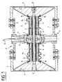
- Figure 1 is an axial sectional view of a transducer of the above type, equipped with two types of devices according to the invention.
- Figure 2 is another view in axial section with two other examples of devices according to the invention.
- the transducers as shown in section in these Figures 1 and 2 therefore comprise in a known manner, two electro-acoustic motors 1 aligned on an axis xx ', placed on either side of a central counterweight 2 and coaxially inside a cylindrical housing 5, which can be called external, covering all of said motors 1 up to the pavilions 3 at the end thereof, the cavity 7, thus delimited by said pavilions , and said housing being filled with liquid 4 in which the whole of the transducer is immersed, such as sea water.
- the characteristics and dimensions of the different parts constituting this assembly as well as of the other elements not shown in these figures, since this is not the aim of the present invention, are such that the Helmholtz frequency of the cavity 7 determined by the housing is close to the fundamental frequency of the axial vibrations of the assembly formed by said electro-acoustic motors 1, said counterweight 2 and said pavilions 3.
- said electro-acoustic motors and the intermediate mass 2 are shown assembled by means of different connecting parts 11, themselves connected to different fixing parts 12, connecting said electro-acoustic motors to the external housing 5.
- the various fastening means are such that they allow freedom of movement, on the one hand of the ends of the electro-acoustic motors on the side of the pavilions, and on the other hand, of the pavilions 3 themselves end relative to said box 5, so as to ensure the full emission of low frequency acoustic waves in the ambient environment.
- the power supply of said electro-acoustic motors 1 is supplied by any power cable 10 fixed to said connection parts 11 by an electrical connector 14.
- the production of such a transducer and all of the various connection parts constituting it are from the field known and achievable by any person skilled in the art: all the other elements making it possible to obtain the Helmholtz frequency as defined above, are not shown here and some have been the subject of various other patent applications such as those in particular cited in the introduction.
- said external housing 5 comprises at least one opening 6 for communication with the outside, said opening possibly consisting of holes distributed around the cylindrical part of the housing or even consisting of a complete circular peripheral opening; moreover, the fact that the cavity 7 is not sealed and communicates with the outside, said end pavilions 3 are not connected at their periphery to the housing 5 and can therefore have freedom of movement all the more.
- the device sealing according to the present invention of the electro-acoustic motors 1 of said submersible transducer, and which are of cylindrical shape with axis xx ', comprises casings 8 also cylindrical, a large part of which closely matches the shape of said motors 1 on their entire length and against their external surface; the other part of the casings 8 consists of a discontinuity 9, giving a capacity for longitudinal elasticity of deformation of the housing 8, in the direction of the axis xx 'of said motors 1.
- said envelopes 8 are closed and sealed both of course along their cylindrical part, and their discontinuity, and at their ends where they are associated with any system of fixing 16, 17 to constitute a sealed box: at one end, they are fixed in a sealed manner to the part 3 integral with the motor 1 and ensuring the emission of the waves emitted by the latter and at the other end to the part 2 blocking the other end of said motor 1.
- the device also preferably comprises a thin film 13 of electrically insulating material, situated against the external surface of said electro-acoustic motors; this said film 13 does not provide a pressure resistance or sealing function, and therefore does not need to be very thick.
- said envelopes 8 are made of a material whose thermal conductivity is high, such as in particular metal or composite resin.
- said discontinuity 9 is produced by at least one fold 92 of small "U" section square in any plane passing through the axis xx '.
- said discontinuity 9 is produced by at least two folds 91 of small sinusoidal section in any plane passing through the axis xx ': in these two embodiments, the folds 91, 92 are of a sufficiently small radius of curvature, so that despite the small thickness of the material constituting the envelopes 8, they can withstand the external pressure, and this small thickness of the material of the envelopes allows the longitudinal elasticity xx 'necessary, thanks to the 'existence said folds making a spring effect.
- said discontinuity 9 is produced by two flanges 9 each situated at the end of two elements 8 phobia, 82 constituting the large continuous part of the casing 8, which flanges being separated and assembled in one sealingly by an elastic seal 15 comprising fixing bolts connected to only one of said flanges and of sufficient thickness to allow the axial displacement of the two elements 81 and 82 relative to each other.
- said discontinuity 9 is produced by a concentric interlocking 93 between two elements 81, 82 also constituting the large continuous part of the casing 8, one of which 82 is sandwiched between the external surface of the motor 1 and the internal surface of the other element 81; it has a part 15 concentric outside the other 82 more extensive than the end of the latter; a seal 18 seals between these two elements, which can thus move axially relative to one another.
- the device comprises two envelopes 8 and each envelope is fixed in a sealed manner at one end 16 to the corresponding flag 3 to the motor 1 concerned and ensuring the emission of the waves emitted by it and at the other end 17, to the central counterweight 2 blocking the other ends of said motors 1.
Description
La présente invention a pour objet des dispositifs d'étanchéité de moteurs acoustiques, en particulier pour des transducteurs immergeables à grande profondeur.The present invention relates to sealing devices for acoustic motors, in particular for submersible transducers at great depth.
Le secteur technique de l'invention est celui de la réalisation de transducteurs électro-acoustiques.The technical sector of the invention is that of the production of electro-acoustic transducers.
L'application principale de l'invention est d'assurer tant l'étanchéité que l'isolation électrique des moteurs électro-acoustiques des transducteurs de type double "Tonpilz", pouvant émettre des ondes acoustiques basses fréquences dans un liquide en immersion illimitée.The main application of the invention is to ensure both the sealing and the electrical insulation of the electro-acoustic motors of transducers of the double "Tonpilz" type, capable of emitting low frequency acoustic waves in a liquid in unlimited immersion.
De tels transducteurs électro-acoustiques immergeables, et en particulier piézo-électriques, comportent un boîtier cylindrique rigide, creux et ouvert à ses deux extrémités axiales, et à l'intérieur duquel sont disposés coaxialement avec celui-ci, deux moteurs électro-acoustiques identiques, placés de part et d'autre d'une contre-masse centrale, et dont les extrémités opposées sont entourées d'un pavillon. Lesdits moteurs électro-acoustiques peuvent être réalisés par deux empilements de plaquettes piézo-électriques alignés. Les faces externes des deux pavillons sont situées dans le plan des extrémités axiales du boîtier, de telle sorte qu'elles sont en contact avec le liquide, dans lequel le boîtier est plongé, et le périmètre externe de ces pavillons vient au plus près du bord des extrémités axiales ouvertes dudit boîtier.Such submersible electro-acoustic transducers, and in particular piezoelectric transducers, comprise a rigid cylindrical housing, hollow and open at its two axial ends, and inside which are arranged coaxially therewith, two identical electro-acoustic motors. , placed on either side of a central counterweight, and whose opposite ends are surrounded by a flag. Said electro-acoustic motors can be produced by two stacks of aligned piezoelectric plates. The external faces of the two flags are located in the plane of the axial ends of the housing, so that they are in contact with the liquid, in which the housing is immersed, and the external perimeter of these flags comes as close as possible to the edge. open axial ends of said housing.
Ainsi, ces faces externes émettent dans le liquide des ondes acoustiques lorsque les moteurs électro-acoustiques sont excités électroniquement : ces transducteurs sont utilisés notamment pour émettre dans l'eau des ondes acoustiques basse-fréquence dans une direction déterminée.Thus, these external faces emit acoustic waves into the liquid when the electro-acoustic motors are electronically excited: these transducers are used in particular to emit low-frequency acoustic waves in water in a determined direction.
Pour éviter la propagation des ondes acoustiques émises par les faces arrière des pavillons, à l'intérieur du boîtier, surtout si celui-ci est également plein de liquide, et qui sont alors retransmises dans le milieu ambiant malgré la rigidité dudit boîtier, deux types de solutions ont été envisagées et proposées telles que :
- l'utilisation de boîtiers étanches remplis de gaz, mais nécessitant soit que le boîtier résiste aux pressions d'immersion dans le liquide, ce qui alourdit considérablement le poids du transducteur quand la profondeur d'immersion est très importante, soit des systèmes de compensation de pression externe par une augmentation de la pression interne de différentes façons, afin de ne pas faire supporter à un boîtier étanche les efforts de résistance à la pression externe : on note par exemple en particulier la demande FR. 2.361.033 déposée par l'Etat Français le 03 Août 1976 sur des transducteurs piézo-électriques et antennes immergeables à grande profondeur, et la demande de brevet No. FR. 2.634.292 de Monsieur Gilles GROSSO et intitulé "procédé et dispositif pour maintenir le gaz contenu dans une enceinte immergée en équilibre de pression avec l'extérieur" déposée le 15 Juillet 1988;.
- l'utilisation de boîtiers rigides mais non étanches, permettant de délimiter une cavité remplie du liquide ambiant à l'arrière des pavillons, dans laquelle on place divers moyens tels que des tubes élastiques fermés, étanches et remplis de gaz, et tel que la fréquence de résonance d'Helmholtz de la cavité soit voisine de la fréquence fondamentale des vibrations axiales de l'ensemble vibrant : un tel dispositif est décrit dans la demande de brevet FR. 2.665.998 du 05 Mai 1988 déposée par l'Etat Français Délégué Général pour l'Armement. On reporte ainsi le problème de la résistance à la pression du boîtier extérieur, à la résistance desdits tubes élastiques, qui étant de diamètres plus faibles, permettent d'avoir un ensemble moins lourd : d'autres moyens peuvent être développés dans le même objectif.
- the use of gas-tight enclosures, but requiring either that the housing withstand the immersion pressures in the liquid, which considerably increases the weight of the transducer when the immersion depth is very large, or external pressure compensation systems by increasing the internal pressure of different ways, so as not to make a sealed housing withstand the forces of resistance to external pressure: there is for example in particular the request FR. 2,361,033 filed by the French State on August 3, 1976 on piezoelectric transducers and submersible antennas at great depth, and patent application No. FR. 2.634.292 by Mr. Gilles GROSSO and entitled "process and device for maintaining the gas contained in an immersed enclosure in pressure balance with the outside" filed on July 15, 1988 ;.
- the use of rigid but not leaktight housings, making it possible to delimit a cavity filled with ambient liquid at the rear of the pavilions, in which various means are placed such as closed elastic tubes, leaktight and filled with gas, and such as the frequency of the Helmholtz resonance of the cavity is close to the fundamental frequency of the axial vibrations of the vibrating assembly: such a device is described in the patent application FR. 2.665.998 of 05 May 1988 filed by the French State General Delegate for Armaments. The problem of resistance to the pressure of the outer casing, to the resistance of said elastic tubes, which are of smaller diameters, is thus transferred to allow a lighter assembly: other means can be developed for the same purpose.
Cette deuxième catégorie de solution permet de s'affranchir des problèmes mécaniques et/ou pneumatiques de la première catégorie, mais pose cependant un autre problème auquel répond la présente invention.This second category of solution makes it possible to overcome the mechanical and / or pneumatic problems of the first category, but nevertheless poses another problem to which the present invention responds.
En effet, les moteurs électro-acoustiques étant directement immergés dans le liquide envahissant la cavité délimitée par le boîtier externe non étanche, doivent être protégés tant sur un plan d'étanchéité contre ce liquide, que sur le plan électrique; pour cela, à ce jour, le pilier de céramique constituant lesdits moteurs électro-acoustiques est enrobé d'un matériau souple de type polyuréthanne ou élastomère, épousant la forme du pilier, acceptant les efforts de la pression externe : il est d'une épaisseur assez importante pour assurer les deux fonctions d'isolation tant d'étanchéité qu'électrique, ces deux notions étant en l'occurrence de même objectif; cependant, si un tel dispositif d'étanchéité, composé dudit matériau, répond bien aux critères d'isolations électriques et d'étanchéité, il freine les échanges thermiques, puisque par définition un bon isolant électrique est aussi un bon isolant thermique, ce qui limite alors la puissance d'émission possible desdits moteurs.Indeed, the electro-acoustic motors being directly immersed in the liquid invading the cavity delimited by the non-watertight external housing, must be protected both on a sealing plane against this liquid, and on the electric plane; for this, to date, the ceramic pillar constituting said electro-acoustic motors is coated with a flexible material of polyurethane or elastomer type, conforming to the shape of the pillar, accepting the forces of external pressure: it is thick important enough to providing the two functions of insulation, both sealing and electrical, these two concepts being in this case the same objective; however, if such a sealing device, composed of said material, meets the criteria of electrical insulation and sealing well, it slows down heat exchange, since by definition a good electrical insulator is also a good thermal insulator, which limits then the possible transmission power of said motors.
On relève également, mais pour d'autres catégories de transducteurs immergeables et pour des objectifs de base différents, le brevet EP 0 247 126 publié le 02 Mai 1990 de la société FERRANTI International en ANGLETERRE, qui décrit, comme dans la présente invention, mais pour une application et un usage spécifiques, une enveloppe métallique externe autour du moteur électro-acoustique : celui-ci est en effet un anneau dont l'émission est donc radiale, contrairement à la présente invention où les moteurs et l'émission sont axiaux, et l'enveloppe, en plus d'une fonction thermique, a un rôle de précontrainte nécessaire pour éviter la rupture de l'anneau.There is also, but for other categories of submersible transducers and for different basic objectives, patent EP 0 247 126 published on May 02, 1990 of the company FERRANTI International in ENGLAND, which describes, as in the present invention, but for a specific application and use, an external metal casing around the electro-acoustic motor: this is in fact a ring whose emission is therefore radial, unlike the present invention where the motors and emission are axial, and the envelope, in addition to a thermal function, has a role of prestressing necessary to avoid rupture of the ring.
On connait également du brevet US-A-5 103 130 des enveloppes étanches pour transducteurs à émission radiale, et comportant une discontinuité longitudinale pour renforcer l'émission d'ondes accoustiques dans la direction de préférence.Also known from US Pat. No. 5,103,130 are sealed envelopes for transducers with radial emission, and comprising a longitudinal discontinuity to reinforce the emission of acoustic waves in the direction preferably.
Le problème posé est donc de pouvoir à la fois protéger les moteurs électro-acoustiques, de forme cylindrique à émission axiale, sur un plan électrique et d'étanchéité par rapport au milieu ambiant, sans l'utilisation de boîtiers rigides externes enveloppant l'ensemble du transducteur et résistant, comme dans ceux de la première catégorie citée précédemment, et de permettre à la fois, sans grande modification des caractéristiques, l'émission et la vibration axiale, et une diffusion thermique des calories produites par lesdits moteurs à toute leur puissance, tout en restant dans la réalisation des boîtiers externes non étanches de transducteurs de la deuxième catégorie citée et sans créer de précontrainte sur les moteurs eux-mêmes.The problem posed is therefore to be able to both protect the electro-acoustic motors, of cylindrical shape with axial emission, on an electrical plane and sealing in relation to the ambient environment, without the use of external rigid casings enveloping the assembly. transducer and resistant, as in those of the first category mentioned above, and to allow both, without much modification of the characteristics, the emission and the axial vibration, and a thermal diffusion of the calories produced by said motors at all their power , while remaining in the realization of the non-waterproof external housings of transducers of the second category mentioned and without creating prestress on the motors themselves.
Une solution au problème posé est un dispositif d'étanchéité de moteurs électro-acoustiques de transducteurs immergeables dans un liquide et de forme cylindrique de section quelconque suivant un axe xx', comportant une enveloppe également cylindrique et concentrique, dont une grande partie épouse la forme dudit moteur sur toute sa longueur et contre sa surface externe; l'autre partie de l'enveloppe est constituée d'une discontinuité donnant une capacité d'élasticité longitudinale de déformation de l'enveloppe dans le sens de l'axe xx' dudit moteur; laquelle enveloppe est fermée, en matériau dont la conductibilité thermique est élevée, et est associée à tout système de fixation à ses extrémités pour constituer un boîtier étanche.A solution to the problem posed is a sealing device for electro-acoustic motors of transducers immersible in a liquid and of cylindrical shape of arbitrary section along an axis xx ', comprising a casing also cylindrical and concentric, a large part of which follows the shape of said motor over its entire length and against its external surface; the other part of the envelope consists of a discontinuity giving a capacity of elasticity longitudinal deformation of the envelope in the direction of the axis xx 'of said motor; which envelope is closed, of material whose thermal conductivity is high, and is associated with any fastening system at its ends to constitute a sealed housing.
De préférence, ledit dispositif comporte un film mince de matériau isolant électriquement situé contre la surface externe dudit moteur électro-acoustique, évitant tout contact direct de celui-ci avec ladite enveloppe; celle-ci est également fixée d'une manière étanche, à une de ses extrémités à la pièce solidaire du moteur et assurant l'émission des ondes émises par celui-ci et à son autre extrémité à la pièce bloquant l'autre extrémité dudit moteur.Preferably, said device comprises a thin film of electrically insulating material situated against the external surface of said electro-acoustic motor, avoiding any direct contact of the latter with said envelope; the latter is also fixed in a sealed manner, at one of its ends to the part integral with the motor and ensuring the emission of the waves emitted by the latter and at its other end to the part blocking the other end of said motor .
Le résultat est de nouveaux dispositifs d'étanchéité de moteurs électro-acoustiques, de transducteurs immergeables, quel que soit en fait le type de transducteurs concernés, car si en effet l'application principale de l'invention est l'étanchéité des moteurs électro-acoustiques, de transducteur de type double "Tonpilz", le dispositif suivant l'invention peut s'appliquer à tout pilier de céramique, et quel que soit le type de transducteurs.The result is new sealing devices for electro-acoustic motors, submersible transducers, regardless of the type of transducers concerned, because if indeed the main application of the invention is the sealing of electro- acoustic, double Tonpilz type transducer, the device according to the invention can be applied to any ceramic pillar, and whatever the type of transducers.
De même, les moteurs électro-acoustiques dont on veut assurer l'étanchéité peuvent être de type piézoélectrique, mais également des cylindres magnétostrictifs entourés d'une bobine d'excitation.Similarly, the electro-acoustic motors which it is desired to seal can be of the piezoelectric type, but also magnetostrictive cylinders surrounded by an excitation coil.
Ainsi, le dispositif suivant la présente invention répond aux divers inconvénients cités précédemment, tout en répondant au problème posé.Thus, the device according to the present invention responds to the various drawbacks mentioned above, while responding to the problem posed.
En effet, la forme particulière de l'enveloppe du dispositif constituant un boîtier interne peut, d'une part soit être résistant en lui-même sans être trop épais du fait de son faible diamètre, surtout si sa section est un cercle, soit permettre à celle-ci de s'appuyer par l'effet de pression externe sur le moteur électro-acoustique lui-même et donc résister ensemble à ladite pression; d'autre part, du fait de ce possible contact ou de sa très faible distance par rapport à celui-ci, surtout si l'on dispose d'un film mince assurant l'isolation électrique suivant la nature du matériau de ladite enveloppe, celle-ci assure l'effet de diffusion thermique des calories émises par le moteur électro-acoustique; de plus, grâce à la discontinuité longitudinale de l'enveloppe, celle-ci ne gène pas la vibration dudit moteur, puisqu'elle peut suivre d'une part, les variations de volume dues à l'immersion et d'autre part les mouvements alternatifs provoqués par la vibration des moteurs en cours d'émission.Indeed, the particular shape of the envelope of the device constituting an internal housing can, on the one hand either be resistant in itself without being too thick because of its small diameter, especially if its section is a circle, or allow to the latter to be supported by the effect of external pressure on the electro-acoustic motor itself and therefore to resist said pressure together; on the other hand, due to this possible contact or its very small distance from it, especially if there is a thin film providing electrical insulation depending on the nature of the material of said envelope, that -this ensures the thermal diffusion effect of the calories emitted by the electro-acoustic motor; in addition, thanks to the longitudinal discontinuity of the envelope, it does not interfere with the vibration of said motor, since it can follow on the one hand, the variations in volume due to immersion and on the other hand the reciprocating movements caused by the vibration of the engines being emitted.
Ainsi, l'enveloppe constituant le boîtier du dispositif suivant l'invention assure au moins une triple fonction d'étanchéité, d'isolation électrique et de diffusion thermique et permet au moteur électro-acoustique auquel elle est associée, de ne pas être tributaire de son immersion, sans alourdir l'ensemble du transducteur concerné et permettant l'émission à toute puissance du moteur qu'elle protège.Thus, the envelope constituting the housing of the device according to the invention ensures at least a triple sealing, electrical insulation and thermal diffusion function and allows the electro-acoustic motor with which it is associated, not to be dependent on its immersion, without weighing down the whole of the transducer concerned and allowing the emission at any power of the motor which it protects.
On pourrait citer d'autres avantages de la présente invention, mais ceux cités ci-dessus en montrent déjà suffisamment pour en démontrer la nouveauté, l'activité inventive et bien sûr l'intérêt.We could cite other advantages of the present invention, but those mentioned above already show enough to demonstrate its novelty, inventive step and of course the advantage.
La description et les figures ci-après représentent des exemples de réalisation de l'invention, mais n'ont aucun caractère limitatif : d'autres réalisations sont possibles dans le cadre de la portée et de l'étendue de la présente invention, surtout en ce qui concerne le type de transducteurs concernés.The description and the figures below represent exemplary embodiments of the invention, but are in no way limiting: other embodiments are possible within the scope and scope of the present invention, especially in regarding the type of transducers involved.
En effet, comme indiqué précédemment, la présente invention peut s'appliquer à tout type de transducteurs, même si dans les exemples cités ci-dessous il n'est décrit, pour des questions de simplification de description et du fait qu'il s'agit d'une application principale de l'invention, que des moteurs électro-acoustiques de transducteurs type double "Tonpilz" de forme cylindrique de révolution.Indeed, as indicated previously, the present invention can be applied to any type of transducers, even if in the examples cited below it is not described, for the sake of simplification of description and the fact that it is a main application of the invention, that electro-acoustic motors of double type transducers "Tonpilz" of cylindrical shape of revolution.
La figure 1 est une vue en coupe axiale d'un transducteur de type ci-dessus, équipé de deux types de dispositifs suivant l'invention.Figure 1 is an axial sectional view of a transducer of the above type, equipped with two types of devices according to the invention.
La figure 2 est une autre vue en coupe axiale avec deux autres exemples de dispositifs suivant l'invention.Figure 2 is another view in axial section with two other examples of devices according to the invention.
Les transducteurs tels que représentés en coupe sur ces figures 1 et 2, comportent donc d'une manière connue, deux moteurs 1 électro-acoustiques alignés sur un axe xx', placés de part et d'autre d'une contre-masse centrale 2 et coaxialement à l'intérieur d'un boîtier 5 cylindrique, que l'on peut appeler externe, recouvrant l'ensemble desdites moteurs 1 jusqu'aux pavillons 3 d'extrémité de ceux-ci, la cavité 7, ainsi délimitée par lesdits pavillons, et ledit boîtier étant remplis du liquide 4 dans lequel l'ensemble du transducteur est immergé, tel que l'eau de mer.The transducers as shown in section in these Figures 1 and 2, therefore comprise in a known manner, two electro-acoustic motors 1 aligned on an axis xx ', placed on either side of a
Dans ce type de transducteurs, les caractéristiques et les dimensions des différentes parties constituant cet ensemble ainsi que des autres éléments non représentés sur ces figures, puisque ce n'est pas le but de la présente invention, sont telles que la fréquence d'Helmholtz de la cavité 7 déterminée par le boîtier soit voisine de la fréquence fondamentale des vibrations axiales de l'ensemble constitué par lesdits moteurs électro-acoustiques 1, ladite contre-masse 2 et lesdits pavillons 3.In this type of transducers, the characteristics and dimensions of the different parts constituting this assembly as well as of the other elements not shown in these figures, since this is not the aim of the present invention, are such that the Helmholtz frequency of the cavity 7 determined by the housing is close to the fundamental frequency of the axial vibrations of the assembly formed by said electro-acoustic motors 1, said
Sur les figures jointes, lesdits moteurs électro-acoustiques et la masse intermédiaire 2 sont représentés assemblés grâce à différentes pièces de liaison 11, reliées elles-mêmes à différentes pièces de fixation 12, reliant lesdits moteurs électro-acoustiques au boîtier externe 5. Les divers moyens de fixation sont tels qu'ils permettent une liberté de déplacement, d'une part des extrémités des moteurs électro-acoustiques du côté des pavillons, et d'autre part, des pavillons 3 eux-mêmes d'extrémité par rapport à ce dit boîtier 5, de façon à assurer la pleine émission d'ondes acoustiques basses fréquences dans le milieu ambiant.In the accompanying figures, said electro-acoustic motors and the
L'alimentation desdits moteurs électro-acoustiques 1 est fournie par tout câble d'alimentation 10 fixé sur lesdites pièces de liaison 11 par un connecteur électrique 14. La réalisation d'un tel transducteur et l'ensemble des différentes pièces de liaison le constituant sont du domaine connu et réalisables par tout homme du métier : tous les autres éléments permettant d'obtenir la fréquence d'Helmholtz telle que définie précédemment, sont non figurés ici et certains ont fait l'objet de diverses autres demandes de brevets comme celles en particulier citées en introduction.The power supply of said electro-acoustic motors 1 is supplied by any
Pour permettre le remplissage de la cavité 7 par ledit liquide 4, ledit boîtier externe 5 comporte au moins une ouverture 6 de communication avec l'extérieur, ladite ouverture pouvant être constituée de trous répartis autour de la partie cylindrique du boîtier ou même constituée d'une ouverture périphérique circulaire complète; de plus, le fait que la cavité 7 n'est pas étanche et communique avec l'extérieur, lesdits pavillons d'extrémité 3 ne sont pas reliés à leur périphérie au boîtier 5 et peuvent d'autant plus avoir une liberté de déplacement.To allow the filling of the cavity 7 with said
Pour permettre cette liberté de déplacement, le dispositif d'étanchéité suivant la présente invention des moteurs électro-acoustiques 1 dudit transducteur immergeable, et qui sont de forme cylindrique d'axe xx', comporte des enveloppes 8 également cylindriques, dont une grande partie épouse au plus près la forme desdits moteurs 1 sur toute leur longueur et contre leur surface externe; l'autre partie des enveloppes 8 est constituée d'une discontinuité 9, donnant une capacité d'élasticité longitudinale de déformation du boîtier 8, dans le sens de l'axe xx' desdits moteurs 1. Pour permettre cette déformation tout en assurant l'étanchéité contre ledit liquide 4 et l'isolation électrique des moteurs électro-acoustiques, lesdites enveloppes 8 sont fermées et étanches tant bien sûr le long de leur partie cylindrique, et de leur discontinuité, qu'à leurs extrémités où elles sont associées à tout système de fixation 16, 17 pour constituer un boîtier étanche : à une extrémité, elles sont fixées d'une manière étanche à la pièce 3 solidaire du moteur 1 et assurant l'émission des ondes émises par celui-ci et à l'autre extrémité à la pièce 2 bloquant l'autre extrémité dudit moteur 1.To allow this freedom of movement, the device sealing according to the present invention of the electro-acoustic motors 1 of said submersible transducer, and which are of cylindrical shape with axis xx ', comprises
Le dispositif comporte également de préférence, un film mince 13 de matériau isolant électriquement, situé contre la surface externe desdits moteurs électro-acoustiques; ce dit film 13 n'assurant pas de fonction de résistance à la pression, ni d'étanchéité, n'a ainsi pas besoin d'être très épais.The device also preferably comprises a
Pour assurer la fonction de radiateur pour diffuser les calories émises par lesdits moteurs électro-acoustiques 1, lesdites enveloppes 8 sont en matériau dont la conductivité thermique est élevée, tel qu'en particulier du métal ou de la résine composite.To perform the function of radiator to diffuse the calories emitted by said electro-acoustic motors 1, said
Sur la partie droite du transducteur représenté à la figure 1, ladite discontinuité 9 est réalisée par au moins une pliure 9₂ de petite section en "U" carré dans tout plan passant par l'axe xx'. Sur la même figure 1, mais en partie gauche, ladite discontinuité 9 est réalisée par au moins deux pliures 9₁ de petite section sinusoïdale dans tout plan passant par l'axe xx' : dans ces deux exemples de réalisation, les pliures 9₁, 9₂ sont d'un rayon de courbure suffisamment faible, pour que malgré la faible épaisseur du matériau constituant les enveloppes 8, elles puissent résister à la pression extérieure, et cette faible épaisseur du matériau des enveloppes permet l'élasticité longitudinale xx' nécessaire, grâce à l'existence desdites pliures faisant un effet ressort.On the right part of the transducer shown in FIG. 1, said discontinuity 9 is produced by at least one
Sur la partie droite de la figure 2, ladite discontinuité 9 est réalisée par deux brides 9 situées chacune à l'extrémité de deux éléments 8₁, 8₂ constituant la grande partie continue de l'enveloppe 8, lesquelles brides étant séparées et assemblées d'une manière étanche par un joint élastique 15 comportant des boulons de fixation reliés à une seule desdites brides et d'épaisseur suffisante pour permettre le déplacement axial des deux éléments 8₁ et 8₂ l'un par rapport à l'autre.On the right part of FIG. 2, said discontinuity 9 is produced by two flanges 9 each situated at the end of two
Sur la partie gauche de cette même figure, ladite discontinuité 9 est réalisée par un emboîtement 9₃ concentrique entre deux éléments 8₁, 8₂ constituant également la grande partie continue de l'enveloppe 8, dont l'un 8₂ est pris en sandwich entre la surface externe du moteur 1 et la surface interne de l'autre élément 8₁; celui-ci comporte une partie 15 concentrique extérieure à l'autre 8₂ plus étendue que l'extrémité de ce dernier; un joint 18 assure l'étanchéité entre ces deux éléments, qui peuvent ainsi se déplacer axialement l'un par rapport à l'autre.On the left part of this same figure, said discontinuity 9 is produced by a
Dans ces différents exemples de réalisation de discontinuité, et dans l'application aux transducteurs de type double "Tonpilz" tels que représentés, le dispositif comporte deux enveloppes 8 et chaque enveloppe est fixée d'une manière étanche à une extrémité 16 au pavillon 3 correspondant au moteur 1 concerné et assurant l'émission des ondes émises par celui-ci et à l'autre extrémité 17, à la contre-masse centrale 2 bloquant les autres extrémités desdits moteurs 1.In these different embodiments of discontinuity, and in the application to transducers of the double "Tonpilz" type as shown, the device comprises two
Claims (8)
- Device for sealing electroacoustic generators in transducers submersible in a liquid (4) and of cylindrical shape and any section along an axis xx', characterised in that it comprises a shell also cylindrical and concentric (8), of which a major part closely fits around the said generator (1) along its entire length and against its outer surface, and of which the other part consists of a discontinuity (9), giving a capability of longitudinal elastic deformation of the shell (8) in the direction of the axis xx' of the said generator (1), the said shell (8) being closed, made of a material whose thermal conductivity is high and combined with any mounting system (16, 17) at its ends to form a watertight box.
- Sealing device according to claim 1, characterised in that the said discontinuity (9) is produced by at least one fold (9₂) of small square "U" section in any plane passing through the axis xx'.
- Sealing device according to claim 1, characterised in that the discontinuity (9) is produced by at least two folds (9₁) of small sinusoidal section in any plane passing through the axis xx'.
- Sealing device according to claim 1, characterised in that the said discontinuity (9) consists of a concentric nesting arrangement (9₃) of two elements (8₁, 8₂) constituting the greater continuous part of the shell (8), one of which (8₂) is sandwiched between the outer surface of the generator (1) and the inner surface of the other element (8₁), the latter comprising a concentric part (15) outside the other (8₂) and extending beyond the end of the latter.
- Sealing device according to claim 1, characterized in that the said discontinuity (9) consists of two flanges (9₄) each located at the end of two elements (8₁, 8₂) forming the greater continuous part of the shell (8), the said flanges being separate and assembled together in a watertight manner by an elastic seal (15) comprising attachment bolts connected to one of the said flanges.
- Sealing device according to any of the claims 1 to 5, characterized in that it comprises a thin film (13) of electrically insulating material positioned against the outer surface of the said electroacoustic generator, preventing any direct contact between this and the said shell (8).
- Sealing device according to any of the claims 1 to 6, characterised in that the said shell (8) is attached in a watertight manner at one end to the horn (3) integral with the generator (1) and assuring the transmission of the waves emitted by the said generator and at the other end to the mass (2) closing the other end of the said generator (1).
- Sealing device according to claim 7, characterised in that it is applied to a transducer comprising two electroacoustic generators (1) aligned on the axis xx', positioned at either side of a central mass (2), and coaxially inside a hollow cylindrical housing (5) covering all of the said generators (1) up to their end horn (3) and filled with the said liquid (4), the said device comprising two shells (8), each attached at one end (16) in a watertight manner to the horn (3) corresponding to the generator (1) concerned, and at the other end (17) to the common central mass (2).
Applications Claiming Priority (2)
| Application Number | Priority Date | Filing Date | Title |
|---|---|---|---|
| FR9213301 | 1992-11-05 | ||
| FR9213301A FR2697709B1 (en) | 1992-11-05 | 1992-11-05 | Sealing device for electro-acoustic motors. |
Publications (2)
| Publication Number | Publication Date |
|---|---|
| EP0600758A1 EP0600758A1 (en) | 1994-06-08 |
| EP0600758B1 true EP0600758B1 (en) | 1995-08-02 |
Family
ID=9435244
Family Applications (1)
| Application Number | Title | Priority Date | Filing Date |
|---|---|---|---|
| EP19930402495 Expired - Lifetime EP0600758B1 (en) | 1992-11-05 | 1993-10-11 | Seal for electro-acoustic motors |
Country Status (5)
| Country | Link |
|---|---|
| EP (1) | EP0600758B1 (en) |
| CA (1) | CA2109465C (en) |
| DE (1) | DE69300325T2 (en) |
| ES (1) | ES2078809T3 (en) |
| FR (1) | FR2697709B1 (en) |
Families Citing this family (5)
| Publication number | Priority date | Publication date | Assignee | Title |
|---|---|---|---|---|
| FR2720585B1 (en) * | 1994-05-26 | 1996-07-05 | France Etat Armement | Electro-acoustic transducer with open sonar antenna. |
| FR2720587B1 (en) * | 1994-05-26 | 1996-07-05 | France Etat Armement | Improvement to sonar antennas provided with a common counterweight. |
| EP0684085A1 (en) * | 1994-05-26 | 1995-11-29 | ETAT FRANCAIS Représenté par le Délégué Général pour l'Armement | Open sonar array comprising electroacoustic transducers |
| FR2728425B1 (en) * | 1994-12-15 | 1997-01-31 | France Etat Armement | ELECTROACOUSTIC LINEAR TRANSMISSION ANTENNA AND TRANSMISSION / RECEPTION ANTENNA COMPRISING SUCH ANTENNA |
| FR2779533B1 (en) * | 1998-06-09 | 2000-08-25 | Total Sa | HIGH RESOLUTION SEISMIC ACQUISITION DEVICE |
Family Cites Families (5)
| Publication number | Priority date | Publication date | Assignee | Title |
|---|---|---|---|---|
| FR2361033A1 (en) * | 1976-08-03 | 1978-03-03 | France Etat | PIEZOELECTRIC TRANSDUCERS AND HIGH DEPTH SUBMERSIBLE ACOUSTICAL ANTENNAS |
| WO1987003448A1 (en) * | 1985-11-30 | 1987-06-04 | Ferranti Plc | Tubular acoustic projector |
| FR2665998B1 (en) * | 1988-05-05 | 1993-10-29 | Etat Francais Delegue Armement | ELECTRO-ACOUSTIC TRANSDUCERS AND METHODS FOR TRANSMITTING LOW FREQUENCY ACOUSTIC WAVES INTO A LIQUID. |
| FR2634292B1 (en) * | 1988-07-15 | 1990-10-19 | Grosso Gilles | METHOD AND DEVICES FOR MAINTAINING THE GAS CONTAINED IN A SUBMERSIBLE PRESSURE BALANCED ENCLOSURE WITH THE OUTSIDE |
| US5103130A (en) * | 1988-12-20 | 1992-04-07 | Rolt Kenneth D | Sound reinforcing seal for slotted acoustic transducers |
-
1992
- 1992-11-05 FR FR9213301A patent/FR2697709B1/en not_active Expired - Fee Related
-
1993
- 1993-10-11 DE DE1993600325 patent/DE69300325T2/en not_active Expired - Fee Related
- 1993-10-11 EP EP19930402495 patent/EP0600758B1/en not_active Expired - Lifetime
- 1993-10-11 ES ES93402495T patent/ES2078809T3/en not_active Expired - Lifetime
- 1993-10-28 CA CA 2109465 patent/CA2109465C/en not_active Expired - Fee Related
Also Published As
| Publication number | Publication date |
|---|---|
| CA2109465C (en) | 2002-01-22 |
| FR2697709A1 (en) | 1994-05-06 |
| DE69300325T2 (en) | 1996-04-18 |
| CA2109465A1 (en) | 1994-05-06 |
| EP0600758A1 (en) | 1994-06-08 |
| FR2697709B1 (en) | 1994-12-30 |
| DE69300325D1 (en) | 1995-09-07 |
| ES2078809T3 (en) | 1995-12-16 |
Similar Documents
| Publication | Publication Date | Title |
|---|---|---|
| EP0462037B1 (en) | Underwater electro-acoustic transducer | |
| EP2670536B1 (en) | Low-frequency electro-acoustic transducer and method of generating acoustic waves | |
| EP0600758B1 (en) | Seal for electro-acoustic motors | |
| EP0367681A1 (en) | Flextensional transducer | |
| EP0684084B1 (en) | Method and transducer for the emission of broadband low frequency acoustic waves in unlimited depth | |
| FR2731129A1 (en) | METHOD AND DEVICE FOR REDUCING THE RESONANCE FREQUENCY OF CAVITIES OF IMMERMABLE TRANSDUCERS | |
| WO1995016211A1 (en) | Electro-acoustic transducer having a mechanical impedance transformer | |
| FR2797552A1 (en) | ELECTRO-ACOUSTIC TRANSDUCER | |
| EP0656232B1 (en) | Method for high power acoustic wave emission and corresponding transducer horns | |
| EP0247126A1 (en) | Tubular acoustic projector. | |
| FR2748183A1 (en) | HYDROPHONE AND METHOD FOR THE PRODUCTION THEREOF | |
| CA2109466C (en) | Method and transducers for transmitting low frequency acoustic waves in a liquid | |
| FR2688972A1 (en) | ELECTRO-ACOUSTIC TRANSDUCERS COMPRISING A FLEXIBLE AND SEALED EMITTING SHELL. | |
| EP0881001B1 (en) | Electrodynamic transducer for underwater acoustics | |
| FR2739521A1 (en) | Pressure resistant piezoelectric transducer for use in sonar antenna | |
| FR2569326A1 (en) | Piezoelectric transducers and sonar antennas capable of being submerged at a great depth | |
| EP0728534A1 (en) | Transducers with light radiating heads submerged in a fluid and process for emitting low-frequency acoustic waves | |
| EP0657868B1 (en) | Process and transducer for emitting very low frequency acoustic waves with high power | |
| CA2306678A1 (en) | Hydrophone for reception of acoustic or seismic waves | |
| FR2728425A1 (en) | Linear electroacoustic antenna for low frequency underwater reception-transmission | |
| FR2697710A1 (en) | Very low frequency sound transmitting procedure for liquid immersion - has flexible elliptical envelope with inlet/outlet holes and acoustic motors mounted internally | |
| FR2720585A1 (en) | Sonar aerial for multi-directional transmission and reception | |
| EP0331591A1 (en) | Electroacoustic capsule with a piezo-electric diaphragm | |
| BE527250A (en) | ||
| FR2783915A1 (en) | Ultrasonic transducer producing high quality acoustic performance uses sensitive element with two electrodes and a protective membrane within an injection molded plastic body |
Legal Events
| Date | Code | Title | Description |
|---|---|---|---|
| PUAI | Public reference made under article 153(3) epc to a published international application that has entered the european phase |
Free format text: ORIGINAL CODE: 0009012 |
|
| 17P | Request for examination filed |
Effective date: 19931026 |
|
| AK | Designated contracting states |
Kind code of ref document: A1 Designated state(s): DE ES GB IT NL |
|
| 17Q | First examination report despatched |
Effective date: 19941017 |
|
| GRAA | (expected) grant |
Free format text: ORIGINAL CODE: 0009210 |
|
| AK | Designated contracting states |
Kind code of ref document: B1 Designated state(s): DE ES GB IT NL |
|
| PG25 | Lapsed in a contracting state [announced via postgrant information from national office to epo] |
Ref country code: GB Effective date: 19950802 |
|
| REF | Corresponds to: |
Ref document number: 69300325 Country of ref document: DE Date of ref document: 19950907 |
|
| ITF | It: translation for a ep patent filed |
Owner name: BARZANO' E ZANARDO MILANO S.P.A. |
|
| REG | Reference to a national code |
Ref country code: ES Ref legal event code: FG2A Ref document number: 2078809 Country of ref document: ES Kind code of ref document: T3 |
|
| GBV | Gb: ep patent (uk) treated as always having been void in accordance with gb section 77(7)/1977 [no translation filed] |
Effective date: 19950802 |
|
| PLBE | No opposition filed within time limit |
Free format text: ORIGINAL CODE: 0009261 |
|
| STAA | Information on the status of an ep patent application or granted ep patent |
Free format text: STATUS: NO OPPOSITION FILED WITHIN TIME LIMIT |
|
| 26N | No opposition filed | ||
| PGFP | Annual fee paid to national office [announced via postgrant information from national office to epo] |
Ref country code: NL Payment date: 20060921 Year of fee payment: 14 |
|
| PGFP | Annual fee paid to national office [announced via postgrant information from national office to epo] |
Ref country code: DE Payment date: 20061009 Year of fee payment: 14 |
|
| PGFP | Annual fee paid to national office [announced via postgrant information from national office to epo] |
Ref country code: ES Payment date: 20061016 Year of fee payment: 14 |
|
| PGFP | Annual fee paid to national office [announced via postgrant information from national office to epo] |
Ref country code: IT Payment date: 20061031 Year of fee payment: 14 |
|
| NLV4 | Nl: lapsed or anulled due to non-payment of the annual fee |
Effective date: 20080501 |
|
| PG25 | Lapsed in a contracting state [announced via postgrant information from national office to epo] |
Ref country code: DE Free format text: LAPSE BECAUSE OF NON-PAYMENT OF DUE FEES Effective date: 20080501 |
|
| PG25 | Lapsed in a contracting state [announced via postgrant information from national office to epo] |
Ref country code: NL Free format text: LAPSE BECAUSE OF NON-PAYMENT OF DUE FEES Effective date: 20080501 |
|
| REG | Reference to a national code |
Ref country code: ES Ref legal event code: FD2A Effective date: 20071013 |
|
| PG25 | Lapsed in a contracting state [announced via postgrant information from national office to epo] |
Ref country code: ES Free format text: LAPSE BECAUSE OF NON-PAYMENT OF DUE FEES Effective date: 20071013 |
|
| PG25 | Lapsed in a contracting state [announced via postgrant information from national office to epo] |
Ref country code: IT Free format text: LAPSE BECAUSE OF NON-PAYMENT OF DUE FEES Effective date: 20071011 |