EP0600634B1 - Electric switch - Google Patents
Electric switch Download PDFInfo
- Publication number
- EP0600634B1 EP0600634B1 EP19930309160 EP93309160A EP0600634B1 EP 0600634 B1 EP0600634 B1 EP 0600634B1 EP 19930309160 EP19930309160 EP 19930309160 EP 93309160 A EP93309160 A EP 93309160A EP 0600634 B1 EP0600634 B1 EP 0600634B1
- Authority
- EP
- European Patent Office
- Prior art keywords
- lid portion
- volume
- plunger
- cowl
- housing
- Prior art date
- Legal status (The legal status is an assumption and is not a legal conclusion. Google has not performed a legal analysis and makes no representation as to the accuracy of the status listed.)
- Expired - Lifetime
Links
Images


Classifications
-
- H—ELECTRICITY
- H01—ELECTRIC ELEMENTS
- H01H—ELECTRIC SWITCHES; RELAYS; SELECTORS; EMERGENCY PROTECTIVE DEVICES
- H01H11/00—Apparatus or processes specially adapted for the manufacture of electric switches
-
- B—PERFORMING OPERATIONS; TRANSPORTING
- B29—WORKING OF PLASTICS; WORKING OF SUBSTANCES IN A PLASTIC STATE IN GENERAL
- B29C—SHAPING OR JOINING OF PLASTICS; SHAPING OF MATERIAL IN A PLASTIC STATE, NOT OTHERWISE PROVIDED FOR; AFTER-TREATMENT OF THE SHAPED PRODUCTS, e.g. REPAIRING
- B29C45/00—Injection moulding, i.e. forcing the required volume of moulding material through a nozzle into a closed mould; Apparatus therefor
- B29C45/16—Making multilayered or multicoloured articles
- B29C45/1676—Making multilayered or multicoloured articles using a soft material and a rigid material, e.g. making articles with a sealing part
-
- H—ELECTRICITY
- H01—ELECTRIC ELEMENTS
- H01H—ELECTRIC SWITCHES; RELAYS; SELECTORS; EMERGENCY PROTECTIVE DEVICES
- H01H13/00—Switches having rectilinearly-movable operating part or parts adapted for pushing or pulling in one direction only, e.g. push-button switch
- H01H13/02—Details
- H01H13/04—Cases; Covers
- H01H13/06—Dustproof, splashproof, drip-proof, waterproof or flameproof casings
- H01H13/063—Casings hermetically closed by a diaphragm through which passes an actuating member
-
- H—ELECTRICITY
- H01—ELECTRIC ELEMENTS
- H01H—ELECTRIC SWITCHES; RELAYS; SELECTORS; EMERGENCY PROTECTIVE DEVICES
- H01H11/00—Apparatus or processes specially adapted for the manufacture of electric switches
- H01H2011/0081—Apparatus or processes specially adapted for the manufacture of electric switches using double shot moulding, e.g. for forming elastomeric sealing elements on form stable casing
Definitions
- This invention relates to electric switches, and more particularly to sealed snap-action electric microswitches and a method of manufacturing such switches.
- Snap-action microswitches commonly comprise a large number - typically eight to ten - of individual components all of which must be assembled together to form the final product. Such assembly can be a delicate, time-consuming and therefore expensive exercise.
- French specification no. 1402906 discloses a microswitch according to the preamble of claim 1, in which the lid portion, the cowl and the plunger are all made from the same material. This material must be relatively rigid to enable the lid portion to perform its normal function without deforming. Consequently, even if the cowl is relatively thin, there is still a severe limitation upon the flexibility of the cowl that can be achieved, because of the inherent rigidity of the material from which it is made.
- US specification no. 3085140 discloses an electric switch which, subsequent to assembly, is encapsulated in a sealing and insulating material.
- a snap-action electric microswitch comprising a housing including a base portion from which project a plurality of electric terminals, a lid portion for location on the base portion to complete the housing, a snap-action mechanism within the housing, an operating plunger slidably mounted in the lid portion to effect actuation of the snap-action mechanism, a peripheral seal member between the lid portion and the base portion of the housing, and a flexible cowl reacting between the plunger and the lid portion of the housing whereby the plunger is sealingly mounted in the lid portion, characterised in that the lid portion and plunger are of a first plastics material and the cowl is of a second plastics material, the lid portion, plunger and cowl being an integral, injection moulded unit, the first and second plastics materials being such that the abutting surfaces of the cowl with the lid portion and with the plunger bond together during the injection moulding process.
- the peripheral seal is of said second plastics material and is formed integrally with the lid portion during the injection moulding process to be welded to the lower periphery of the lid portion during said process.
- the lid portion and plunger comprise a glass-filled polyamide
- the cowl and peripheral seal comprise a thermoplastic elastomer
- the fixed upper portion and the at least one core of the moulding tool are such that, on defining said second volume, a third volume corresponding in shape with that of the peripheral seal between the lid portion and the base portion of the housing is defined within the tool, the second and third volumes being interconnected whereby, on injection of said second plastics material into the second and third volumes, a peripheral seal is formed around, to be bonded to, the periphery of the lid portion.
- the moulding tool includes a first removable core which, together with the fixed upper portion, defines said first volume, and a second removable core which, together with the fixed upper portion, defines said second volume, while it is further preferred that the second removable core, together with said fixed upper portion of the tool, also defines said third volume.
- the switch of the invention can be such as to consist of only three separate components that must thereafter be assembled together, namely a base portion with integral terminals, a lid portion with integral plunger, cowl and peripheral seal, and the snap-action mechanism itself.
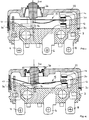
- the illustrated switch is of relatively conventional overall construction in its lower and intermediate regions, comprising a moulded base portion 2, typically of a glass-filled polyamide, in which are encapsulated an anchor terminal 4, a bottom contact terminal 6 and a top contact terminal 8, said terminals respectively including, above the base portion 2, an anchor member 10, a bottom contact 12 and a top contact 14.
- a support member 16 integral with the anchor terminal 4 and having a notched face thereto upstands from the base portion 2 to complete the mounting for a conventional snap-action mechanism indicated generally at 18 and including a contact member 20 movable between a first position engaging the contact 14 and a second position engaging the contact 12 thereby to alter the electrical condition of the switch.
- the switch is completed by a lid portion 22 which incorporates the novel features of the invention as will be apparent from the following description.
- the lid portion 22 is injection moulded from a glass-filled polyamide and includes an aperture therethrough in which is located an operating plunger 24 of the same material.
- the plunger 24 is guided in said movement by co-operation with the support member 16. More particularly, and as best seen in Fig.
- the support member 16 is of generally U-shape in front view, the plunger 24 being provided with a pair of grooves 28 one in each side face thereof.
- the inside edges of the upstanding arms of the support member 16 are received one in each groove 28 in the plunger 24 whereby said arms and grooves 28 co-operate to guide the plunger 24 in its upward and downward movement, said movement serving to alter the condition of the snap-action mechanism, and therefore of the switch itself, in conventional manner.
- the lid portion 22 of the switch is a snap-fit on the base portion 2 to encapsulate the snap-action mechanism 18 and associated components therein, a peripheral seal 30 reacting between the abutting faces of the lid portion 22 and the base portion 2 to effect a seal therebetween.
- the seal 30 is of the same thermoplastic elastomer material as the cowl 26 and, as with the cowl, is integrally bonded to the periphery of the lid portion 22.
- a moulding tool including a fixed body portion 32 and a first removable core 34 which together define volumes 36 and 38 shaped to comprise the lid portion 22 and plunger 24 of the switch.
- the material of these components typically a glass-filled polyamide, is injected into the tool to define the lid portion 22 and the plunger 24.
- the first core 34 is then removed from the tool and is replaced by a second core 40 which, together with the body portion 32 and the pre-formed components 22 and 24, defines further interconnected volumes 42, 44 shaped to comprise the cowl 26 and peripheral seal 30.
- the material of these components typically a thermoplastic elastomer, is injected into the tool to define the cowl 26 and the seal 30.
- the cowl 26 is of generally annular configuration with the inner periphery thereof abutting the plunger 24 and the outer periphery thereof abutting the sidewalls of a defining aperture in the lid portion 22.
- the seal 30 is formed in, to engage with, a peripheral recess formed around the lower surface of the lid portion 22, and includes an upstanding one end portion 30' located externally of the lid portion 22.
- the materials of the first and second moulding stages are such that, at all interfaces and as a result of the heat generated during the moulding process, said materials are welded together to form permanent bonds therebetween.
- the cowl 26 is effectively integrated with the lid portion 22 and the plunger 24 to effect a flexible seal therebetween, while the seal 30 is permanently attached to the underside of the lid portion 22.
- a plunger operated snap-action microswitch in which the lid portion, the plunger, the flexible cowl between the lid portion and the plunger, and the peripheral seal around the lid portion constitute a single component which, together with a snap-action mechanism and a preformed base region in which are encapsulated the terminals of the switch, enables the switch to be assembled from only three parts, thereby making such assembly a much more convenient, quick and therefore inexpensive exercise compared with conventional methods.
- the moulding tool instead of incorporating two removable cores 34, 40, may be provided with a single core comprising a plurality of adjustable components the positions of which, relative to the fixed body portion 32, can be altered to define the various volumes 36, 38, 42, 44 within the tool as and when required.
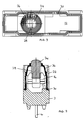
- the switch may be provided with a bottom cover indicated generally at 46 which is a sealing snap fit onto the base portion 2 to encapsulated the terminals 4, 6, 8.
- the cover 46 is injection moulded from a glass-filled polyamide with an integral peripheral seal 48 and an annular end gland 50 of a thermoplastic elastomer being formed during the injection moulding process in a manner similar to that described above in relation to the lid portion 22 and the seal 30.
- the materials of the cover 46, the seal 48 and the gland 50 are such that, at all interfaces and as a result of the heat generated during the moulding process, said materials are welded together to form permanent bonds therebetween.
- the seal 48 and gland 50 are integral with the cover 46, and, on location of the cover 46 on the base portion 2, a seal is effected between the cover 46 and the base portion 2.
- the leads (not shown) from the terminals 4, 6, 8 are fed through the gland 50.
- the cover 46 is then snapped onto the base portion 2 to effect a seal therebetween without the necessity for injecting a sealing compound into the volume between the cover 46 and the base portion 2 as has been required heretofore.
Description
- This invention relates to electric switches, and more particularly to sealed snap-action electric microswitches and a method of manufacturing such switches.
- Snap-action microswitches commonly comprise a large number - typically eight to ten - of individual components all of which must be assembled together to form the final product. Such assembly can be a delicate, time-consuming and therefore expensive exercise.
- It has been proposed to provide a moulded base portion to the switch housing in which are encapsulated the electrical terminals of the switch, and whereby the base portion and said terminals comprise a single unit thus reducing the number of separate components to the switch.
- However, there still remain as separate components, as well as the snap-action mechanism itself, the lid portion of the housing, the seal between the lid portion and the base portion of the housing, the operating plunger and the sealing cowl between the plunger and the lid portion.
- It is essential to ensure that the interior of the housing is completely sealed, and there are various methods used to secure and seal the cowl to the lid portion, for example stretching the cowl over the plunger to utilise its inherent elasticity to effect the seal or sticking the cowl to the plunger and the associated region of the housing.
- Such procedures are again awkward to carry out, while switches can be subjected to large numbers of operations which require the seals therearound to be capable of withstanding extensive flexing and distortion.
- French specification no. 1402906 discloses a microswitch according to the preamble of
claim 1, in which the lid portion, the cowl and the plunger are all made from the same material. This material must be relatively rigid to enable the lid portion to perform its normal function without deforming. Consequently, even if the cowl is relatively thin, there is still a severe limitation upon the flexibility of the cowl that can be achieved, because of the inherent rigidity of the material from which it is made. - US specification no. 3085140 discloses an electric switch which, subsequent to assembly, is encapsulated in a sealing and insulating material.
- It would be desirable to be able to provide a snap-action microswitch capable of more ready assembly than heretofore, and a method of manufacturing the same.
- According to a first aspect of the present invention there is provided a snap-action electric microswitch comprising a housing including a base portion from which project a plurality of electric terminals, a lid portion for location on the base portion to complete the housing, a snap-action mechanism within the housing, an operating plunger slidably mounted in the lid portion to effect actuation of the snap-action mechanism, a peripheral seal member between the lid portion and the base portion of the housing, and a flexible cowl reacting between the plunger and the lid portion of the housing whereby the plunger is sealingly mounted in the lid portion, characterised in that the lid portion and plunger are of a first plastics material and the cowl is of a second plastics material, the lid portion, plunger and cowl being an integral, injection moulded unit, the first and second plastics materials being such that the abutting surfaces of the cowl with the lid portion and with the plunger bond together during the injection moulding process.
- Preferably the peripheral seal is of said second plastics material and is formed integrally with the lid portion during the injection moulding process to be welded to the lower periphery of the lid portion during said process.
- Conveniently the lid portion and plunger comprise a glass-filled polyamide, and the cowl and peripheral seal comprise a thermoplastic elastomer.
- According to a second aspect of the present invention there is provided a method of manufacturing the aforesaid snap-action electric microswitch including the steps of:
- providing a moulding tool having a fixed upper portion and at least one core capable of defining, together with said fixed upper portion, a first volume within the tool corresponding in shape with that of the lid portion and the plunger of the switch, and a second volume within the tool corresponding in shape with that of the cowl, said second volume communicating with regions of said first volume;
- defining said first volume within the moulding tool;
- injecting a first plastics material into said first volume to form said lid portion and said plunger;
- defining said second volume within the moulding tool, and
- injecting a second plastics material into said second volume to form said cowl,
- the first and second plastics materials being welded together during the injection moulding process whereby the cowl is bonded to both the lid portion and the plunger to effect a flexible seal therebetween.
- In a preferred method, the fixed upper portion and the at least one core of the moulding tool are such that, on defining said second volume, a third volume corresponding in shape with that of the peripheral seal between the lid portion and the base portion of the housing is defined within the tool, the second and third volumes being interconnected whereby, on injection of said second plastics material into the second and third volumes, a peripheral seal is formed around, to be bonded to, the periphery of the lid portion.
- Preferably, the moulding tool includes a first removable core which, together with the fixed upper portion, defines said first volume, and a second removable core which, together with the fixed upper portion, defines said second volume, while it is further preferred that the second removable core, together with said fixed upper portion of the tool, also defines said third volume.
- Thus it will be appreciated that the switch of the invention can be such as to consist of only three separate components that must thereafter be assembled together, namely a base portion with integral terminals, a lid portion with integral plunger, cowl and peripheral seal, and the snap-action mechanism itself.
- By way of example only, the aspects of the invention will now be described in greater detail with reference to the accompanying drawings of which:
- Figs. 1 and 2 are a longitudinal vertical section and a transverse vertical section respectively of a switch according to the invention in its inoperative condition;
- Fig. 3 is a plan view from below of the lid portion and attached components of the switch of Figs. 1 and 2;
- Fig. 4 is a longitudinal vertical section equivalent to that of Fig. 1 but with the switch in its operative condition;
- Fig. 5 is the switch of Fig. 1 with a bottom cover thereon enclosing the terminals of the switch;
- Fig. 6 is a vertical section through a moulding tool incorporating a first removable core for forming the lid portion and plunger of a switch according to the invention, and
- Fig. 7 is a vertical section through the tool of Fig. 6 incorporating a second removable core for forming the cowl and peripheral seal of a switch according to the invention.
- Referring to the drawings, the illustrated switch is of relatively conventional overall construction in its lower and intermediate regions, comprising a
moulded base portion 2, typically of a glass-filled polyamide, in which are encapsulated ananchor terminal 4, a bottom contact terminal 6 and atop contact terminal 8, said terminals respectively including, above thebase portion 2, ananchor member 10, abottom contact 12 and atop contact 14. - A
support member 16 integral with theanchor terminal 4 and having a notched face thereto upstands from thebase portion 2 to complete the mounting for a conventional snap-action mechanism indicated generally at 18 and including acontact member 20 movable between a first position engaging thecontact 14 and a second position engaging thecontact 12 thereby to alter the electrical condition of the switch. - The switch is completed by a
lid portion 22 which incorporates the novel features of the invention as will be apparent from the following description. - The
lid portion 22 is injection moulded from a glass-filled polyamide and includes an aperture therethrough in which is located anoperating plunger 24 of the same material. Aflexible cowl 26, typically of a thermoplastic elastomer, surrounds theplunger 24 and is integrally bonded to both theplunger 24 and the defining edge of said aperture in thelid portion 22 as clearly seen in Figs. 1 and 4 to effect a seal between theplunger 24 and thelid portion 22 whilst permitting upward and downward movement of theplunger 24 relative to thelid portion 22 between the positions shown in Figs. 1 and 4. Theplunger 24 is guided in said movement by co-operation with thesupport member 16. More particularly, and as best seen in Fig. 2, thesupport member 16 is of generally U-shape in front view, theplunger 24 being provided with a pair ofgrooves 28 one in each side face thereof. The inside edges of the upstanding arms of thesupport member 16 are received one in eachgroove 28 in theplunger 24 whereby said arms andgrooves 28 co-operate to guide theplunger 24 in its upward and downward movement, said movement serving to alter the condition of the snap-action mechanism, and therefore of the switch itself, in conventional manner. - The
lid portion 22 of the switch is a snap-fit on thebase portion 2 to encapsulate the snap-action mechanism 18 and associated components therein, aperipheral seal 30 reacting between the abutting faces of thelid portion 22 and thebase portion 2 to effect a seal therebetween. - More particularly, the
seal 30 is of the same thermoplastic elastomer material as thecowl 26 and, as with the cowl, is integrally bonded to the periphery of thelid portion 22. - The method by which the
lid portion 22,cowl 26 andseal 30 are integrated with one another can be appreciated with reference to Figs. 6 and 7. - Referring to these figures, there is shown a moulding tool including a
fixed body portion 32 and a firstremovable core 34 which together definevolumes lid portion 22 andplunger 24 of the switch. The material of these components, typically a glass-filled polyamide, is injected into the tool to define thelid portion 22 and theplunger 24. - The
first core 34 is then removed from the tool and is replaced by asecond core 40 which, together with thebody portion 32 and thepre-formed components interconnected volumes 42, 44 shaped to comprise thecowl 26 andperipheral seal 30. The material of these components, typically a thermoplastic elastomer, is injected into the tool to define thecowl 26 and theseal 30. - The
cowl 26 is of generally annular configuration with the inner periphery thereof abutting theplunger 24 and the outer periphery thereof abutting the sidewalls of a defining aperture in thelid portion 22. - The
seal 30 is formed in, to engage with, a peripheral recess formed around the lower surface of thelid portion 22, and includes an upstanding one end portion 30' located externally of thelid portion 22. - The materials of the first and second moulding stages are such that, at all interfaces and as a result of the heat generated during the moulding process, said materials are welded together to form permanent bonds therebetween.
- So the
cowl 26 is effectively integrated with thelid portion 22 and theplunger 24 to effect a flexible seal therebetween, while theseal 30 is permanently attached to the underside of thelid portion 22. - Thus there is provided a plunger operated snap-action microswitch in which the lid portion, the plunger, the flexible cowl between the lid portion and the plunger, and the peripheral seal around the lid portion constitute a single component which, together with a snap-action mechanism and a preformed base region in which are encapsulated the terminals of the switch, enables the switch to be assembled from only three parts, thereby making such assembly a much more convenient, quick and therefore inexpensive exercise compared with conventional methods.
- The moulding tool, instead of incorporating two
removable cores fixed body portion 32, can be altered to define thevarious volumes - Referring to Fig. 5, the switch may be provided with a bottom cover indicated generally at 46 which is a sealing snap fit onto the
base portion 2 to encapsulated theterminals - More particularly, the
cover 46 is injection moulded from a glass-filled polyamide with an integralperipheral seal 48 and anannular end gland 50 of a thermoplastic elastomer being formed during the injection moulding process in a manner similar to that described above in relation to thelid portion 22 and theseal 30. The materials of thecover 46, theseal 48 and thegland 50 are such that, at all interfaces and as a result of the heat generated during the moulding process, said materials are welded together to form permanent bonds therebetween. Thus theseal 48 andgland 50 are integral with thecover 46, and, on location of thecover 46 on thebase portion 2, a seal is effected between thecover 46 and thebase portion 2. - Prior to snap-fitting the
cover 46 onto the base portion, the leads (not shown) from theterminals gland 50. Thecover 46 is then snapped onto thebase portion 2 to effect a seal therebetween without the necessity for injecting a sealing compound into the volume between thecover 46 and thebase portion 2 as has been required heretofore.
Claims (9)
- A snap-action electric microswitch comprising a housing including a base portion (2) from which project a plurality of electric terminals (4, 6, 8), a lid portion (22) for location on the base portion (2) to complete the housing, a snap-action mechanism (18) within the housing, an operating plunger (24) slidably mounted in the lid portion (22) to effect actuation of the snap-action mechanism (18) , a peripheral seal (30) between the lid portion (22) and the base portion (2) of the housing, and a flexible cowl (26) reacting between the plunger (24) and the lid portion (22) of the housing whereby the plunger (24) is sealingly mounted in the lid portion (22), characterised in that the lid portion (22) and plunger (24) are of a first plastics material and the cowl (26) is of a second plastics material, the lid portion (22), plunger (24) and cowl (26) being an integral, injection moulded unit, the first and second plastics materials being such that the abutting surfaces of the cowl (26) with the lid portion (22) and with the plunger (24) bond together during the injection moulding process.
- A microswitch as claimed in claim 1 in which the peripheral seal (30) is of said second plastics material and is formed integrally with the lid portion (22) during the injection moulding process to be welded to the lower periphery of the lid portion (22) during said process.
- A microswitch as claimed in claim 2 in which the lid portion (22) and plunger (24) comprise a glass-filled polyamide, and the cowl (26) and the peripheral seal (30) comprise a thermoplastic elastomer.
- A microswitch as claimed in any one of claims 1 to 3 in which the housing further comprises a cover portion (46) sealingly located on the base portion (2) to encase the terminals (4, 6, 8), a peripheral seal (48) being located between the cover portion (46) and the base portion (2).
- A microswitch as claimed in claim 4 in which the cover portion (46) is injection moulded, the peripheral seal (48) being formed integrally with the cover portion during the injection moulding process to be welded to the upper periphery of the cover portion (46) during said process.
- A method of manufacturing a snap-action electric microswitch as claimed in any one of claims 1 to 5, the method comprising the steps of:providing a moulding tool having a fixed upper portion (32) and at least one core (34, 40) capable of defining, together with said fixed upper portion (32), a first volume (36, 38) within the tool corresponding in shape with that of the lid portion (22) and the plunger (24) of the switch, and a second volume (42) within the tool corresponding in shape with that of the cowl (26), said second volume (42) communicating with regions of said first volume (36, 38);defining said first volume (36, 38) within the moulding tool;injecting a first plastics material into said first volume (36, 38) to form said lid portion (22) and said plunger (24);defining said second volume (42) within the moulding tool, andinjecting a second plastics material into said second volume (42) to form said cowl (26),the first and second plastics materials being welded together during the injection moulding process whereby the cowl (26) is bonded to both the lid portion (22) and the plunger (24) to effect a flexible seal therebetween.
- A method as claimed in claim 6 in which the fixed upper portion (32) and the at least one core of the moulding tool are such that, on defining said second volume (42), a third volume (44) corresponding in shape with that of the peripheral seal (30) between the lid portion (22) and the base portion (2) of the housing is defined within the tool, the second and third volumes (42, 44) being interconnected whereby, on injection of said second plastics material into the second and third volumes (42, 44), a peripheral seal (3) is formed around, to be bonded to, the periphery of the lid portion (22).
- A method as claimed in claim 6 or claim 7 in which the moulding tool includes a first removable core (34) which, together with the fixed upper portion (32), defines said first volume (36, 38), and a second removable core (40) which, together with the fixed upper portion (32), defines said second volume (42).
- A method as claimed in claim 8 together with claim 7 in which the second removable core (40), together with the fixed upper portion (32), further defines said third volume (44).
Applications Claiming Priority (2)
| Application Number | Priority Date | Filing Date | Title |
|---|---|---|---|
| GB929225052A GB9225052D0 (en) | 1992-11-30 | 1992-11-30 | Electric switch |
| GB9225052 | 1992-11-30 |
Publications (2)
| Publication Number | Publication Date |
|---|---|
| EP0600634A1 EP0600634A1 (en) | 1994-06-08 |
| EP0600634B1 true EP0600634B1 (en) | 1996-01-31 |
Family
ID=10725898
Family Applications (1)
| Application Number | Title | Priority Date | Filing Date |
|---|---|---|---|
| EP19930309160 Expired - Lifetime EP0600634B1 (en) | 1992-11-30 | 1993-11-17 | Electric switch |
Country Status (3)
| Country | Link |
|---|---|
| EP (1) | EP0600634B1 (en) |
| DE (1) | DE69301454T2 (en) |
| GB (1) | GB9225052D0 (en) |
Cited By (1)
| Publication number | Priority date | Publication date | Assignee | Title |
|---|---|---|---|---|
| CN108214349A (en) * | 2017-12-29 | 2018-06-29 | 广东欧珀移动通信有限公司 | For the side switch positioning device of electronic device |
Families Citing this family (16)
| Publication number | Priority date | Publication date | Assignee | Title |
|---|---|---|---|---|
| DE9409268U1 (en) * | 1994-06-08 | 1994-09-08 | Burgess Gmbh | Microswitch |
| JP2699936B2 (en) * | 1995-06-06 | 1998-01-19 | 日本電気株式会社 | Method for producing composite molded body |
| US5667060A (en) * | 1995-12-26 | 1997-09-16 | Amerace Corporation | Diaphragm seal for a high voltage switch environment |
| DE19604530C1 (en) * | 1996-02-08 | 1997-04-03 | Maico Elektroapparate | Fan casing with covering rim and additional closure providing secure, accurate sealing |
| DE19903838C1 (en) * | 1999-02-01 | 2000-07-20 | Moeller Gmbh | Push-button, especially for electrical control unit has pressure piece and surrounding collar seal produced by two-component injection of plastics which form no adhesive bond |
| EP1054420A1 (en) * | 1999-05-18 | 2000-11-22 | Molex Incorporated | Keyboard for an electrical or electronic apparatus and method of making the same |
| AU2002213735A1 (en) * | 2001-11-21 | 2003-06-10 | Phonak Ag | Switch cover |
| DE10254912B3 (en) * | 2002-11-25 | 2004-09-02 | Tyco Electronics Amp Gmbh | Method and mold for manufacturing a composite workpiece by plastic injection |
| AT504267B1 (en) * | 2005-03-18 | 2013-06-15 | Pollmann Austria Ohg | CONSTRUCTION UNIT WITH ELECTRIC SWITCHING FUNCTION |
| DE102014006943A1 (en) * | 2014-02-15 | 2015-08-20 | Johnson Electric Germany GmbH & Co. KG | Electric switch having a top surface housing |
| DE102014005433A1 (en) | 2014-02-15 | 2015-08-20 | Johnson Electric Germany GmbH & Co. KG | Microswitch with a formed from switch base and switch cover housing |
| DE102014006033A1 (en) | 2014-02-15 | 2015-08-20 | Johnson Electric Germany GmbH & Co. KG | An electrical microswitch comprising at least one electrical contact and method of manufacturing an electrical microswitch |
| GB2558415B (en) | 2015-05-22 | 2019-02-06 | Dyson Technology Ltd | A hand held appliance |
| FR3105557B1 (en) * | 2019-12-20 | 2022-03-18 | Legrand France | Waterproof electrical switch |
| FR3105560B1 (en) * | 2019-12-20 | 2022-03-04 | Legrand France | Waterproof electrical switch |
| CN112837955A (en) * | 2020-12-30 | 2021-05-25 | 歌尔科技有限公司 | Key mechanism and wearable equipment with same |
Family Cites Families (4)
| Publication number | Priority date | Publication date | Assignee | Title |
|---|---|---|---|---|
| GB789752A (en) * | 1955-06-21 | 1958-01-29 | Smith & Sons Ltd S | Improvements in or relating to enclosed electric switches |
| US3085140A (en) * | 1959-02-24 | 1963-04-09 | Robertshaw Fulton Controls Co | Encapsulated switch |
| FR1402906A (en) * | 1964-03-12 | 1965-06-18 | Crouzet Sa | Device for sealing devices such as snap-action contactors with a plastic enclosure |
| FR1410425A (en) * | 1964-07-29 | 1965-09-10 | Crouzet Sa | Means for making apparatus such as electrical snap-action switches, contactors or reversers hermetic |
-
1992
- 1992-11-30 GB GB929225052A patent/GB9225052D0/en active Pending
-
1993
- 1993-11-17 EP EP19930309160 patent/EP0600634B1/en not_active Expired - Lifetime
- 1993-11-17 DE DE1993601454 patent/DE69301454T2/en not_active Expired - Fee Related
Cited By (2)
| Publication number | Priority date | Publication date | Assignee | Title |
|---|---|---|---|---|
| CN108214349A (en) * | 2017-12-29 | 2018-06-29 | 广东欧珀移动通信有限公司 | For the side switch positioning device of electronic device |
| CN108214349B (en) * | 2017-12-29 | 2019-08-02 | Oppo广东移动通信有限公司 | Side switch positioning device for electronic device |
Also Published As
| Publication number | Publication date |
|---|---|
| DE69301454T2 (en) | 1996-09-05 |
| EP0600634A1 (en) | 1994-06-08 |
| DE69301454D1 (en) | 1996-03-14 |
| GB9225052D0 (en) | 1993-01-20 |
Similar Documents
| Publication | Publication Date | Title |
|---|---|---|
| EP0600634B1 (en) | Electric switch | |
| US4324956A (en) | Fluid-proof slide switch | |
| US5343008A (en) | Sealed switch | |
| EP1158554B1 (en) | A rocker switch and seal arrangement | |
| JP3677079B2 (en) | Molding method for molding electrical components into associated plastic housings | |
| WO1998015431A1 (en) | Snap-on airbag and horn switch module | |
| US6093900A (en) | Actuatable switch in sealed housing | |
| JPH0773776A (en) | Microswitch | |
| US4690484A (en) | Wafer and method for manufacturing switch wafer | |
| CN1132070C (en) | Assembly comprising hard plastic watch case and at least one push button, and method for manufacturing such assembly | |
| EP0807973A3 (en) | Plastic molded type semiconductor device and method of manufacturing the same | |
| US4972057A (en) | Push button switch | |
| CN113692631B (en) | Waterproof electrical switch assembly | |
| US5107083A (en) | Resiliently deformable pushbutton switch having a contact member carrying a conductive material | |
| KR970000483A (en) | Composite molded product and method of manufacturing the product | |
| US5842561A (en) | Push-button switch with bridge section integrally connecting movable contact and fixed contact | |
| EP1389789B1 (en) | Multifunctional pushbutton switch | |
| CN1047018C (en) | Push-button switch | |
| JP3151534B2 (en) | Pushbutton switch and method of manufacturing the same | |
| JPS63164127A (en) | Manufacture of switch | |
| JP2000179751A5 (en) | ||
| EP0789373B1 (en) | Electric switch | |
| JPH08115634A (en) | Key top sheet | |
| JPH04349318A (en) | Slide switch and manufacture thereof | |
| JP3274690B2 (en) | Switch and method of manufacturing switch |
Legal Events
| Date | Code | Title | Description |
|---|---|---|---|
| PUAI | Public reference made under article 153(3) epc to a published international application that has entered the european phase |
Free format text: ORIGINAL CODE: 0009012 |
|
| AK | Designated contracting states |
Kind code of ref document: A1 Designated state(s): CH DE FR GB IT LI |
|
| 17P | Request for examination filed |
Effective date: 19940704 |
|
| 17Q | First examination report despatched |
Effective date: 19950419 |
|
| GRAA | (expected) grant |
Free format text: ORIGINAL CODE: 0009210 |
|
| AK | Designated contracting states |
Kind code of ref document: B1 Designated state(s): CH DE FR GB IT LI |
|
| REF | Corresponds to: |
Ref document number: 69301454 Country of ref document: DE Date of ref document: 19960314 |
|
| ITF | It: translation for a ep patent filed |
Owner name: MODIANO & ASSOCIATI S.R.L. |
|
| ET | Fr: translation filed | ||
| PLAV | Examination of admissibility of opposition |
Free format text: ORIGINAL CODE: EPIDOS OPEX |
|
| PLBQ | Unpublished change to opponent data |
Free format text: ORIGINAL CODE: EPIDOS OPPO |
|
| PLBI | Opposition filed |
Free format text: ORIGINAL CODE: 0009260 |
|
| PLAV | Examination of admissibility of opposition |
Free format text: ORIGINAL CODE: EPIDOS OPEX |
|
| PLBF | Reply of patent proprietor to notice(s) of opposition |
Free format text: ORIGINAL CODE: EPIDOS OBSO |
|
| 26 | Opposition filed |
Opponent name: CHERRY MIKROSCHALTER GMBH Effective date: 19961028 |
|
| PLBF | Reply of patent proprietor to notice(s) of opposition |
Free format text: ORIGINAL CODE: EPIDOS OBSO |
|
| PLBF | Reply of patent proprietor to notice(s) of opposition |
Free format text: ORIGINAL CODE: EPIDOS OBSO |
|
| PLBF | Reply of patent proprietor to notice(s) of opposition |
Free format text: ORIGINAL CODE: EPIDOS OBSO |
|
| PLBO | Opposition rejected |
Free format text: ORIGINAL CODE: EPIDOS REJO |
|
| APAC | Appeal dossier modified |
Free format text: ORIGINAL CODE: EPIDOS NOAPO |
|
| APAE | Appeal reference modified |
Free format text: ORIGINAL CODE: EPIDOS REFNO |
|
| APAC | Appeal dossier modified |
Free format text: ORIGINAL CODE: EPIDOS NOAPO |
|
| APAC | Appeal dossier modified |
Free format text: ORIGINAL CODE: EPIDOS NOAPO |
|
| PLBN | Opposition rejected |
Free format text: ORIGINAL CODE: 0009273 |
|
| STAA | Information on the status of an ep patent application or granted ep patent |
Free format text: STATUS: OPPOSITION REJECTED |
|
| 27O | Opposition rejected |
Effective date: 19980214 |
|
| REG | Reference to a national code |
Ref country code: GB Ref legal event code: IF02 |
|
| APAH | Appeal reference modified |
Free format text: ORIGINAL CODE: EPIDOSCREFNO |
|
| PGFP | Annual fee paid to national office [announced via postgrant information from national office to epo] |
Ref country code: DE Payment date: 20071128 Year of fee payment: 15 |
|
| PGFP | Annual fee paid to national office [announced via postgrant information from national office to epo] |
Ref country code: CH Payment date: 20071123 Year of fee payment: 15 Ref country code: IT Payment date: 20071129 Year of fee payment: 15 |
|
| PGFP | Annual fee paid to national office [announced via postgrant information from national office to epo] |
Ref country code: GB Payment date: 20071120 Year of fee payment: 15 Ref country code: FR Payment date: 20071121 Year of fee payment: 15 |
|
| REG | Reference to a national code |
Ref country code: CH Ref legal event code: PL |
|
| GBPC | Gb: european patent ceased through non-payment of renewal fee |
Effective date: 20081117 |
|
| PG25 | Lapsed in a contracting state [announced via postgrant information from national office to epo] |
Ref country code: IT Free format text: LAPSE BECAUSE OF NON-PAYMENT OF DUE FEES Effective date: 20081117 |
|
| REG | Reference to a national code |
Ref country code: FR Ref legal event code: ST Effective date: 20090731 |
|
| PG25 | Lapsed in a contracting state [announced via postgrant information from national office to epo] |
Ref country code: LI Free format text: LAPSE BECAUSE OF NON-PAYMENT OF DUE FEES Effective date: 20081130 Ref country code: DE Free format text: LAPSE BECAUSE OF NON-PAYMENT OF DUE FEES Effective date: 20090603 Ref country code: CH Free format text: LAPSE BECAUSE OF NON-PAYMENT OF DUE FEES Effective date: 20081130 |
|
| PG25 | Lapsed in a contracting state [announced via postgrant information from national office to epo] |
Ref country code: GB Free format text: LAPSE BECAUSE OF NON-PAYMENT OF DUE FEES Effective date: 20081117 |
|
| PG25 | Lapsed in a contracting state [announced via postgrant information from national office to epo] |
Ref country code: FR Free format text: LAPSE BECAUSE OF NON-PAYMENT OF DUE FEES Effective date: 20081130 |