EP0600523A1 - Reverse rotation preventing mechanism in spinning reel for fishing - Google Patents
Reverse rotation preventing mechanism in spinning reel for fishing Download PDFInfo
- Publication number
- EP0600523A1 EP0600523A1 EP93119996A EP93119996A EP0600523A1 EP 0600523 A1 EP0600523 A1 EP 0600523A1 EP 93119996 A EP93119996 A EP 93119996A EP 93119996 A EP93119996 A EP 93119996A EP 0600523 A1 EP0600523 A1 EP 0600523A1
- Authority
- EP
- European Patent Office
- Prior art keywords
- reverse rotation
- rotor
- rotation prevention
- claw
- quill
- Prior art date
- Legal status (The legal status is an assumption and is not a legal conclusion. Google has not performed a legal analysis and makes no representation as to the accuracy of the status listed.)
- Granted
Links
Images


Classifications
-
- A—HUMAN NECESSITIES
- A01—AGRICULTURE; FORESTRY; ANIMAL HUSBANDRY; HUNTING; TRAPPING; FISHING
- A01K—ANIMAL HUSBANDRY; CARE OF BIRDS, FISHES, INSECTS; FISHING; REARING OR BREEDING ANIMALS, NOT OTHERWISE PROVIDED FOR; NEW BREEDS OF ANIMALS
- A01K89/00—Reels
- A01K89/01—Reels with pick-up, i.e. with the guiding member rotating and the spool not rotating during normal retrieval of the line
- A01K89/0117—Anti-reverse mechanisms
-
- A—HUMAN NECESSITIES
- A01—AGRICULTURE; FORESTRY; ANIMAL HUSBANDRY; HUNTING; TRAPPING; FISHING
- A01K—ANIMAL HUSBANDRY; CARE OF BIRDS, FISHES, INSECTS; FISHING; REARING OR BREEDING ANIMALS, NOT OTHERWISE PROVIDED FOR; NEW BREEDS OF ANIMALS
- A01K89/00—Reels
- A01K89/01—Reels with pick-up, i.e. with the guiding member rotating and the spool not rotating during normal retrieval of the line
- A01K89/0114—Reciprocating mechanisms
Definitions
- the present device relates to a reverse rotation prevention mechanism which is in a spinning reel for fishing and includes a roller-type clutch.
- the circumferential velocity of the roller contact surface of the quill is so low that there is a problem that the rollers are not instantaneously and surely pinched between the quill and the ratchet to prevent the reverse rotation thereof.
- the engagement surfaces of the components of the mechanism are likely to be locally loaded in the engagement of the components for the prevention of the reverse rotation of the ratchet so as to be deformed, there is a problem that the durability of the mechanism is low.
- the roller-type one-way clutch is a generally purchasable one, the inside and outside diameters thereof are limited so as to lower the degree of freedom of design of the mechanism to cause a problem that the mechanism is not appropriate to a compact reel.
- the ratchet is rotated in kinematic conjunction with the rotation of the rotor or the spool in the direction or the winding of the fishline so as to move the claw out of the position of the engagement with the ratchet to make it impossible to instantaneously prevent the reverse rotation of the rotor of the spool.
- the present device was made in order to solve the problems mentioned above. Accordingly, it is an object of the device to provide a reverse rotation prevention mechanism which is for a spinning reel for fishing and is such that the reverse rotation of the rotor of the reel is instantaneously and surely prevented by the mechanism, the durability of the mechanism is high, the dimensions of the mechanism are not much restricted, the degree of freedom of design of the mechanism is high, and the mechanism is appropriate to a compact reel as well.
- the rotor is secured to a rotary quill, which is rotated by the turning of a handle in kinematic conjunction therewith, a reverse rotation prevention member having reverse rotation prevention engagement portions is rotatably supported concentrically to the quill, a reverse rotation prevention claw is supported by the body of the reel so as to be swingable and is urged by a spring so as to be capable of being engaged with one of the engagement portions, and a roller-type clutch is provided between the rotor and the reverse rotation prevention member so as to kinematically connect the rotor and the member to each other when the rotor is reversely rotated in such a direction as to unwind a fishline.
- Figs. 1, 2, 3 and 4 show a reverse rotation prevention mechanism which is the first embodiment and is for a spinning reel for fishing.
- a ring 10 is fitted on a rotary quill 2 projecting forward from the body 1 of the reel, and a rotor 3 is fitted on the quill in front of the ring and secured to the quill by a nut 11, as shown in Fig. 1, so that the rotor is rotated by the turning of a candle 12 in kinematic conjunction therewith.
- a spool 14 is supported on the front end portion of a spool shaft 13 fitted in the rotary quill 2 and projecting therefrom, so that the spool is reciprocated backward and forward by the turning of the handle 12 in kinematic conjunction therewith.
- a reverse rotation prevention member 4 is rotatably supported on the ring 10, and includes a perfectly circular portion 4a on which a plurality of rollers 15 are provided, and a plurality of reverse rotation prevention engagement portions 4b.
- the tip portion 5a of a reverse rotation prevention claw 5 is located near the reverse rotation prevention engagement portions 4b of the member 4 so that the tip portion can be engaged with one of the engagement portions, as shown in Fig. 2.
- the claw 5 is supported by the body 1 of the reel so that the claw can be swung.
- a spring 16 urges the claw 5 in such a direction as to engage the tip portion 5a thereof with one of the rotation prevention engagement portions 4b.
- the position of the claw 5 is controlled by a cam member 17 so that the tip portion 5a of the claw is engaged with or disengaged from the engagement portion 4b.
- the rotor 3 has an annular projection 3a extending in the rear recess of the rotor and having a plurality of recesses 3c having bottoms 3b extending nearly in the circumferential direction of the rotor and slightly outward in the direction of the reverse rotation of the rotor, as shown in Fig. 3.
- the rollers 15 are provided in the recesses 3c and urged by springs 6 counterclockwise with regard to Fig. 3.
- Each of the springs 6 includes pushing portion 6a for pushing the roller 15 on the outside circumferential surface thereof, a coming-off prevention portion 6b located in contact with the end face of the rotor to prevent it from coming off, and a secured portion 6c, as shown in Fig. 4.
- the secured portion 6c is fitted in the groove 3d of the annular projection 3a of the rotor 3 and secured thereto by a screw 18.
- the roller-type clutch of the reverse rotation prevention mechanism includes the reverse rotation prevention member 4, the recesses 3c, the rollers 15, and the springs 6.
- the handle 12 is turned in such a direction that a fishline not shown in the drawings is wound on the spool 14, the rotor 3 is rotated clockwise with regard to Fig. 2 and the rotary quill 2 and the rotor are rotated counterclockwise with regard to Fig. 3.
- the rollers 15 are rotated in the recesses 3c so that the rotor 3 and the reverse rotation prevention member 4 are not kinematically connected to each other. For that reason, the member 4 engaged at the engagement portion 4b thereof with the tip portion 5a of the reverse rotation prevention claw 5 as shown in Fig. 2 is not rotated.
- the member cannot be rotated, namely, the rotor 3 cannot be reversely rotated any more. If the claw 5 is swung counterclockwise by the cam member 17 against the urging force of the spring 16 in advance, as shown by a two dot chain line in Fig. 2, so that the tip portion 5a of the claw is disengaged from the engagement portion 4b of the member 4, the rotor 3 and the member can be reversely rotated continuously.
- the perfectly circular portion 4a of the reverse rotation prevention member 4 is large in diameter, the circumferential velocity of the roller contact surface of the portion is high enough to immediately prevent the reverse rotation of the rotor 3 and reverse rotation prevention mechanism is high in durability. Since the mechanism is not much restricted of the dimensions thereof, the mechanism is high in the degree of freedom of design. Therefore, the mechanism is appropriate to a compact reel as well.
- Figs. 5 and 6 show a reverse rotation prevention mechanism which is a modification of the embodiment described above.
- a rotor 3 has an annular projection 3a formed separately from the body of the rotor.
- a ring 7 of the same form as the annular projection 3a is secured to the rotor 3 by a plurality of screws 19.
- a reverse rotation prevention member 4 includes a perfectly circular portion 4a on which a plurality of rollers 15 are provided, a plurality of reverse rotation prevention engagement portions 4b, and a plurality of roller coming-off prevention portions 4c for preventing the rollers from coming off.
- Springs 6 have no roller coming-off prevention portion.
- the ring 7 has a plurality of recesses 7b having bottoms 7a extending nearly in the circumferential direction of the ring and slightly outward in the direction of the reverse rotation of the rotor 3.
- the springs 6 and the roller coming-off prevention portions 4c in the embodiment and the modification may be otherwise shaped and secured.
- the modification is the same in operation and effect as the embodiment.
- Figs. 7 and 8 show a reverse rotation prevention mechanism which is the second embodiment and is for a spinning reel for fishing.
- a rotor 3 is not provided with an annular projection and a ring such as those 3a and 7 in the preceding embodiment, and a reverse rotation prevention member 8 has recesses 8a in which rollers 15 are provided and which have bottoms 8b extending nearly in the circumferential direction of the member and slightly outward in the direction of the reverse rotation of the rotor.
- the member 8 further includes a plurality of reverse rotation prevention engagement portions 8c, and coming-off prevention portions 8d.
- the rollers 15 are provided in the recesses 8a of the member 8 and located in contact with the inside circumferential surface 3d of the rotor 3, which extends around the recess of the rotor. Springs for pushing the rollers 15 may be either provided or not provided.
- the tip portion 5a of a reverse rotation prevention claw 5a is located near the engagement portions 8c of the reverse rotation prevention member 8 so that the tip portion can be engaged with one of the engagement portions.
- the claw 5 is supported by the body 1 of the reel so that the claw can be swung.
- a spring 16 urges the claw 5 in such a direction as to engage the tip portion 5a thereof with one of the engagement portions 8c.
- each of the rollers 15 is pinched between the inside circumferential surface 3d of the rotor and the bottom 8b of the recess 8a of the member 8 so that the rotor and the member are kinematically connected to each other to transmit the torque of the rotor to the member to rotate it in the same direction as the rotor.
- the engagement portion 8c of the member 8 is already engaged with the tip portion 5a of the claw 5 as shown in Fig. 8, the member cannot be rotated, namely, the rotor 3 cannot be reversely rotated any more.
- Figs. 9, 10 and 11 show a reverse rotation prevention mechanism which is the third embodiment and is for a spinning reel for fishing.
- a rotor 3 has annular projection 3a of the same form as that shown in Figs. 1 and 3, and a reverse rotation prevention member 9 is rotatably supported on the outside circumferential surface of a cylindrical portion 1a projecting forward from the body 1 of the reel, and includes a perfectly circular portion 9a on which balls 19 are provided, a plurality of reverse rotation prevention engagement portions 9b, and ball coming-off prevention portions 9c located in contact with the spherical surfaces of the balls to prevent them from coming off.
- Fig. 9 shows a reverse rotation prevention mechanism which is the third embodiment and is for a spinning reel for fishing.
- a rotor 3 has annular projection 3a of the same form as that shown in Figs. 1 and 3
- a reverse rotation prevention member 9 is rotatably supported on the outside circumferential surface of a cylindrical portion 1a projecting forward from the body 1 of the reel,
- the tip portion 5a of a reverse rotation prevention claw 5 is located near the reverse rotation prevention portions 9b of the member 9 so that the tip portion can be engaged with one of the reverse rotation prevention portions.
- the claw 5 is supported by the body 1 of the reel so that the claw can be swung.
- a spring 16 urges the claw 5 in such a direction as to engage the tip portion 5a thereof with the engagement portion 9b of the member 9.
- the position of the claw 5 is controlled by a cam member 17 so that the tip portion 5a of the claw 5 is engaged with or disengaged from the engagement portion 9b of the member 9.
- the rotor 3 has the annular projection 3a formed in the rear recess of the rotor and having a plurality of recesses 3c having bottoms 3b extending nearly in the circumferential direction of the projection and slightly outward in the direction of the reverse rotation of the rotor, as shown in Fig. 11.
- the balls 19 are provided in the recesses 6c. Springs 6 urge the balls 19 counterclockwise with regard to Fig. 11.
- the member cannot be rotated, namely, the rotor cannot be reversely rotated any more. If the claw 5 is swung counterclockwise against the urging force of the spring 16 in advance as shown by a two-dot chain line in Fig. 10, the rotor 3 can be reversely rotated continuously.
- Figs. 12, 13, 14, 15 and 16 show a reverse rotation prevention mechanism which is the fourth embodiment and is in a spinning reel for fishing.
- the position of the claw 105 is controlled by a cam 6a of cam member 106 so that the claw can be engaged with or disengaged from the ratchet 104b.
- a torsion spring 117 is provided between the body 101 of the reel and the spring engagement part 106b of the cam member 106.
- the cam member 106 is secured to a manipulation bar 118 at the front end portion thereof.
- a knob 119 is secured to the bar 118 at its rear portion projecting from the rear of the reel body 101.
- Figs. 13 and 15 show the state that the knob 119 is swung into an engagement position ("ON" position) to engage the engagement portion 105b of the claw 105 in the notch 104c of the ratchet 104b.
- the ratchet 104b would be likely to be rotted in kinematic conjunction with the rotation of the rotor 103 in the direction of the winding of the fishline.
- the ratchet 104b has the notches 104c
- the claw 105 has the engagement portion 105b to be engaged in the notch
- the notch, the engagement portion and the spring 116 constitute the means for preventing the claw from being disengaged from the ratchet
- the rotary member 104 and the ratchet thereof are prevent from being rotated in kinematic conjunction with the rotation of the rotor 103 in the direction of the winding of the fishline. For that reason, the rotor 103 and the rotary member 104 are instantaneously prevented from being reversely rotated.
- Figs. 16, 17, 18, 19 and 20 show a reverse rotation prevention mechanism which is the fifth embodiment and is for a spinning reel for fishing.
- the mechanism includes a deformed cam member 106 for manipulating a reverse rotation prevention engagement claw 105, but does not include a member such as the spring 116 of the preceding embodiment.
- the ratchet 104b of the rotary member 104 of the mechanism does not have notches such as those of the preceding embodiment.
- the claw 105 does not have an engagement portion which is a stepped portion, at the tip portion 105a of the claw.
- the cam member 106 is fitted on a secured member 108 secured to a manipulation bar 118, so that the cam member can be swung.
- a screw 121 is engaged in the cam member 106 and fitted in the groove 108a of the secured member 108 to prevent the cam member from coming off the secured member.
- the cam member 106 is formed with a pin 6c put in the slender hole 5c of the claw 105.
- a knob 119 When a knob 119 is in an engagement position ("ON" position), the pin 106c is located slightly rightward from a vertical line with regard to Fig. 16.
- a projection 108b is provided on the outside circumferential surface of the front end portion of the secured member 108 and fitted in the arc-shaped recess 106d of the cam member 106.
- a spring 122 is provided between the projection 108b and the cam member 106, and urges the cam member.
- the secured member 108 has a spring engagement portion 108c with which a torsion spring 117 is engaged.
- the rotary member 104 is not rotated. Since there is a resistance to the rotation of the roller-type one-way clutch of the reverse rotation prevention mechanism in the direction for the disengagement of the clutch and the rotation speed of the rotor 103 has an influence, the ratchet 104b would be likely to be rotated in kinematic conjunction with the rotation of the rotor in the direction of the winding of the fishline. However, since the pin 106c in the slender hole 105c of the claw 105 is located slightly rightward from the vertical line with regard to Fig.
- the cam member 106 and the claw are not swung, so that a means for preventing the claw from being disengaged from the ratchet 104b acts to surely keep the rotary member 104 from being rotated in kinematic conjunction with the rotation of the rotor 103 in the direction for the winding of the fishline.
- the rotor 103 is reversely rotated counterclockwise with regard to Fig. 16.
- each of the rollers 115 is pinched between the bottom of the recess 103c and the perfectly circular portion 104c of the rotary member 104 so that the rotor and the member are kinematically connected to each other to transmit the torque of the rotor to the member to rotate it in the same direction as the rotor.
- the ratchet 104b of the rotary member 104 is already engaged with the tip portion 105a of the claw 105 as shown in Figs. 16, 17, 18 and 19, the rotary member cannot be rotated, namely, the rotor 103 cannot be reversely rotated any more.
- the ratchet 104b and the claw 105 may be provided with notches and an engagement portion, respectively, in the same manner as the preceding embodiment.
- Fig. 21 shows a reverse rotation prevention mechanism which is a modification of the embodiment shown in Figs. 16, 17, 18, 19 and 20.
- a cam member 106 has a groove 106e instead of a pin
- a reverse rotation prevention engagement claw 105 has a pin 105d fitted in the groove.
- Figs. 22, 23 and 24 show a reverse rotation prevention mechanism which is the sixth embodiment and is for a spinning reel for fishing.
- the roller-type one-way clutch of the reverse rotation prevention mechanism shown in Fig. 12 includes the rotary member 104, the recesses 103c, the rollers 115 and the springs 107, that of the reverse rotation prevention mechanism shown in Fig.
- roller 22 includes a plurality of roller 124 fitted in the peripheral portion of a ring 123 fitted on the outside circumferential surface of a rotary quill 102, a rotary member 104 having a ratchet 104b having notches 104c and constituting the peripheral portion of the clutch, an outer ring 109a, recesses 109b provided in the inner circumferential portion of the outer ring, slopes 109c provided on the portion, spacers 125, and springs 126, as shown in Figs. 23 and 24.
- the rollers 124 are kept at equal intervals by the spacers 125.
- the springs 126 urge the rollers 124 toward the slopes 109c.
- the quill 102 and the rotary member 104 cannot be reversely rotated continuously if a reverse rotation prevention engagement claw 105 is engaged with the ratchet 104b of the rotary member, and the quill and the rotary member can be reversely rotated continuously if the claw is disengaged from the ratchet, similarly to the embodiment shown in Fig. 12.
- the engagement and disengagement of the claw 105 and the ratchet 105 are performed in the same manner as the embodiment shown in Fig. 12.
- the present invention is not confined thereto but may be embodied for another type of a reel such as a reel whose spool shaft is supported at both the ends thereof.
- a reel whose spool shaft is supported at both the ends thereof.
- the above sentence “since the rotation speed of the rotor 103 has an influence, the ratchet 104b would be likely to be rotated in kinematic conjunction with the rotation of the rotor in the direction for the winding of the fishline.” is replaced by a sentence "since the rotation speed of a spool has an influence, a ratchet would be likely to be rotated in kinematic conjunction with the rotation of the spool in the direction for the winding of a fishline or with the rotation of a drive member which is rotated in kinematic conjunction with the spool.”
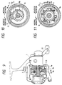
- Figs. 25 and 26 show a reverse rotation preventing mechanism which is the seventh embodiment and is in a spinning reel for fishing.
- each of clutch gears 206 which is fixedly secured to an outer peripheral surface of a roller-type one-way bearing 207 is pivotally supported to a bottom portion of a rotor 203b in parallel relation to a rotor quill 202.
- the clutch gears 206 are engaged with a gear portion 204a of a reverse rotation prevention member 204 which is rotatably supported to the rotor quill 202 through a collar 210.
- a reverse rotation prevention claw 205 can be engaged with one of the reverse rotation preventing engagement portions 204b which are provided to the member 204.
- the claw 205 is always urged by an urging means such as a spring member (not shown in the drawings) in such a direction as to engage the tip portion thereof with one of the engagement portions 204b when a fishline is wound on the spool.
- a clutch gear supporting member 220 is secured to the bottom portion 203b of the rotor 203 by a screw.
- the rotor 203 is reversely rotated clockwise with regard to Fig. 26.
- the rotation of the clutch gears 206 in the clockwise direction is locked by the roller-type one-way bearing 207 so that the force for rotating the engagement portion 204b of the member 204 in the clockwise direction with regard to Fig. 26 is applied thereto.
- the reverse rotation preventing member 204 can not be reversely rotated any more. Therefore, the reverse rotation of the rotor 203 can be surely prevented.
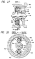
- Fig. 27 and 28 show a reverse rotation preventing mechanism which is the eighth embodiment and is in a spinning reel for fishing.
- each of clutch gears 306 which is fixedly secured to an outer peripheral surface of a roller-type one-way bearing 307 is rotatably supported in a backward recess portion of the rotor 303 in parallel relation to a rotor quill 302.
- a reverse rotation prevention member 304 is rotatably supported on the rotor quill 302.
- Each of clutch gears 306 is engaged with the inner gear 308 provided to an inner peripheral surface of the rotor 303 and a reverse rotation preventing claw 305 is engaged with one of engagement portions 304b provided to the member 304.
- a reverse rotation preventing mechanism provided in accordance with the present device, in a spinning reel for fishing, since the roller-type one-way clutches are provided between the rotor and the reverse rotation prevention member, the engagement surfaces of the components of the mechanism are not to be locally loaded. Therefore, the durability of he engagement surfaces in the reverse rotation of the rotor can be enhanced and the high precision can be maintained in a long period. Besides, since the prevention member are provided to the reverse rotation prevention claw and a member corresponding to the claw, and the claw remains engaged with the ratchet without a clearance between them, the rotor is surely and instantaneously prevented from rotating reversely.
- the clutch member is provided within the limited space, that is, the space between the rotor and the reverse rotation prevention member, so as to utilize usefully there, the mechanism can be appropriate to a compact reel.
- the weight of the construction becomes to be light and the manufacture cost can be reduced.
Abstract
Description
- The present device relates to a reverse rotation prevention mechanism which is in a spinning reel for fishing and includes a roller-type clutch.
- Although the reverse rotation of a ratchet is conventionally prevented by a reverse rotation prevention claw engaged with the ratchet, there is a problem that since the number of the teeth of the ratchet is small, the angle of the play of the ratchet until the completion of the prevention of the reverse rotation thereof is too large to quickly prevent the reverse rotation by engaging the claw with the ratchet.
- To solve the problem, a reverse rotation prevention mechanism in which a roller-type one-way clutch is fitted in a ratchet not to rotate relative thereto and the rollers of the clutch are fitted in the peripheral portion of a rotary quill to make it possible to prevent the reverse rotation of the ratchet with less play thereof until the completion of the prevention was proposed as disclosed in the Japan Utility Model Application (OPI) No. 38963/89 (the term "OPI" as used herein means an "unexamined published application").
- However, since the diameter of the rotary quill in which the rollers of the roller-type one-way clutch of the mechanism disclosed in the Japan Utility Model Application mentioned above are fitted is small, the circumferential velocity of the roller contact surface of the quill is so low that there is a problem that the rollers are not instantaneously and surely pinched between the quill and the ratchet to prevent the reverse rotation thereof. Besides, since the engagement surfaces of the components of the mechanism are likely to be locally loaded in the engagement of the components for the prevention of the reverse rotation of the ratchet so as to be deformed, there is a problem that the durability of the mechanism is low. In addition, since the roller-type one-way clutch is a generally purchasable one, the inside and outside diameters thereof are limited so as to lower the degree of freedom of design of the mechanism to cause a problem that the mechanism is not appropriate to a compact reel.
- Further, since there is a resistance to the rotation of the roller-type one-way clutch itself in the direction for the disengagement thereof and the rotation speed of the rotor of the spinning reel or that of the spool of a reel whose spool shaft is supported at both the ends thereof has an influence, the ratchet is rotated in kinematic conjunction with the rotation of the rotor or the spool in the direction or the winding of the fishline so as to move the claw out of the position of the engagement with the ratchet to make it impossible to instantaneously prevent the reverse rotation of the rotor of the spool.
- The present device was made in order to solve the problems mentioned above. Accordingly, it is an object of the device to provide a reverse rotation prevention mechanism which is for a spinning reel for fishing and is such that the reverse rotation of the rotor of the reel is instantaneously and surely prevented by the mechanism, the durability of the mechanism is high, the dimensions of the mechanism are not much restricted, the degree of freedom of design of the mechanism is high, and the mechanism is appropriate to a compact reel as well.
- In the reverse rotation prevention mechanism provided in accordance with the present invention, the rotor is secured to a rotary quill, which is rotated by the turning of a handle in kinematic conjunction therewith, a reverse rotation prevention member having reverse rotation prevention engagement portions is rotatably supported concentrically to the quill, a reverse rotation prevention claw is supported by the body of the reel so as to be swingable and is urged by a spring so as to be capable of being engaged with one of the engagement portions, and a roller-type clutch is provided between the rotor and the reverse rotation prevention member so as to kinematically connect the rotor and the member to each other when the rotor is reversely rotated in such a direction as to unwind a fishline.
-
- Fig. 1 is a partially sectional side view of a spinning reel which is for fishing and provided with a reverse rotation prevention mechanism which is an embodiment of the present device;
- Fig. 2 is an enlarged sectional view of the reel along a line II-II shown in Fig. 1;
- Fig. 3 is an enlarged sectional view of he reel along a line III-III shown in Fig. 1;
- Fig. 4 is a perspective view of the spring of the mechanisms;
- Fig. 5 is a partially sectional side view of a spinning reel which is for fishing and provided with a reverse rotation prevention mechanism which is a modification of the embodiment;
- Fig. 6 is an enlarged sectional view of the reel along a line VI-VI shown in Fig. 5;
- Fig. 7 is a partially sectional side view of a spinning reel which is for fishing and provided with a reverse rotation prevention mechanism which is another embodiment of the present device;
- Fig. 8 is an enlarged sectional view of the reel along line VIII-VIII shown in Fig. 7;
- Fig. 9 is a partially sectional side view of a spinning reel which is for fishing and provided with a reverse rotation prevention mechanism which is yet another embodiment of the present device;
- Fig. 10 is an enlarged sectional view of the reel along aline X-X shown in Fig. 9;
- Fig. 11 is an enlarged sectional view of the reel along a line XI-XI shown in Fig. 9;
- Fig. 12 is a partially sectional side view of a spinning reel which is for fishing and provided with a reverse rotation prevention mechanism which is an embodiment of the present device;
- Fig. 13 is a sectional view of the mechanism along a line XIII-XIII shown in Fig. 12, in the state that an engagement claw is engaged with a ratchet;
- Fig. 14 is a sectional view of the mechanism along a line XIV-XIV shown in Fig. 12;
- Fig. 15 is an enlarged sectional view of a major part of the mechanism;
- Fig. 16 is a sectional view of a reverse rotation prevention mechanism which is another embodiment of the present device and is for a spinning reel for fishing, along a line corresponding to that XIII-XIII shown in Fig. 12, in the state that an engagement claw is engaged with a ratchet;
- Fig. 17 is a sectional view of a the cam member of the mechanism shown in Fig. 16;
- Figs. 18 and 19 are enlarged sectional views of a major part of the mechanism shown in Fig. 16;
- Fig. 20 is a sectional view of the major part in the state that the claw is disengaged from the ratchet;
- Fig. 21 is a sectional view of a major part of a reverse rotation prevention mechanism which is a modification of the mechanism shown in Fig. 16;
- Fig. 22 is a partially sectional side view of a spinning reel which is for fishing and provided with a reverse rotation prevention mechanism which is yet another embodiment of the present device;
- Fig. 23 is a sectional view of the mechanism along a line XXIII-XXIII shown in Fig. 22;
- Fig. 24 is an enlarged sectional view of the mechanism along the line XXIII-XXIII;
- Fig. 25 is a partially sectional side view of a spinning reel which is for fishing and provided with a reverse rotation prevention mechanism which is yet another embodiment of the present invention;
- Fig. 26 is an enlarged sectional view of the reel along a line XXVI-XXVI shown in Fig. 25;
- Fig. 27 is a partially sectional side view of a spinning reel which is for fishing and provided with a reverse rotation prevention mechanism which is yet another embodiment of the present invention; and
- Fig. 28 is an enlarged sectional view of the reel along a line XXVIII-XXVIII shown in Fig. 27.
- Embodiments of the present device are hereafter described with reference to the drawings attached hereto.
- Figs. 1, 2, 3 and 4 show a reverse rotation prevention mechanism which is the first embodiment and is for a spinning reel for fishing. In the reel, a
ring 10 is fitted on arotary quill 2 projecting forward from the body 1 of the reel, and arotor 3 is fitted on the quill in front of the ring and secured to the quill by anut 11, as shown in Fig. 1, so that the rotor is rotated by the turning of acandle 12 in kinematic conjunction therewith. Aspool 14 is supported on the front end portion of aspool shaft 13 fitted in therotary quill 2 and projecting therefrom, so that the spool is reciprocated backward and forward by the turning of thehandle 12 in kinematic conjunction therewith. - A reverse
rotation prevention member 4 is rotatably supported on thering 10, and includes a perfectlycircular portion 4a on which a plurality ofrollers 15 are provided, and a plurality of reverse rotationprevention engagement portions 4b. Thetip portion 5a of a reverserotation prevention claw 5 is located near the reverse rotationprevention engagement portions 4b of themember 4 so that the tip portion can be engaged with one of the engagement portions, as shown in Fig. 2. Theclaw 5 is supported by the body 1 of the reel so that the claw can be swung. Aspring 16 urges theclaw 5 in such a direction as to engage thetip portion 5a thereof with one of the rotationprevention engagement portions 4b. The position of theclaw 5 is controlled by acam member 17 so that thetip portion 5a of the claw is engaged with or disengaged from theengagement portion 4b. - The
rotor 3 has an annular projection 3a extending in the rear recess of the rotor and having a plurality ofrecesses 3c having bottoms 3b extending nearly in the circumferential direction of the rotor and slightly outward in the direction of the reverse rotation of the rotor, as shown in Fig. 3. Therollers 15 are provided in therecesses 3c and urged bysprings 6 counterclockwise with regard to Fig. 3. Each of thesprings 6 includes pushingportion 6a for pushing theroller 15 on the outside circumferential surface thereof, a coming-offprevention portion 6b located in contact with the end face of the rotor to prevent it from coming off, and a secured portion 6c, as shown in Fig. 4. The secured portion 6c is fitted in thegroove 3d of the annular projection 3a of therotor 3 and secured thereto by ascrew 18. - The roller-type clutch of the reverse rotation prevention mechanism includes the reverse
rotation prevention member 4, therecesses 3c, therollers 15, and thesprings 6. When thehandle 12 is turned in such a direction that a fishline not shown in the drawings is wound on thespool 14, therotor 3 is rotated clockwise with regard to Fig. 2 and therotary quill 2 and the rotor are rotated counterclockwise with regard to Fig. 3. At that time, therollers 15 are rotated in therecesses 3c so that therotor 3 and the reverserotation prevention member 4 are not kinematically connected to each other. For that reason, themember 4 engaged at theengagement portion 4b thereof with thetip portion 5a of the reverserotation prevention claw 5 as shown in Fig. 2 is not rotated. When the fishline wound on thespool 14 is then unwound therefrom by the pull of a fish, therotor 3 is reversely rotated counterclockwise with regard to Fig. 2 or clockwise with regard to Fig. 3. At that time, because of the reverse rotation of therotor 3, each of therollers 15 is pinched between the perfectlycircular portion 4a of the reverserotation prevention member 4 and thebottom 3b of therecess 3c of the rotor so that the rotor and the member are kinematically connected to each other to transmit the torque of the rotor to the member to rotate it in the same direction as the rotor. However, since theengagement portion 4b of themember 4 is already engaged with thetip portion 5a of the reverserotation prevention claw 5 as shown in Fig. 2, the member cannot be rotated, namely, therotor 3 cannot be reversely rotated any more. If theclaw 5 is swung counterclockwise by thecam member 17 against the urging force of thespring 16 in advance, as shown by a two dot chain line in Fig. 2, so that thetip portion 5a of the claw is disengaged from theengagement portion 4b of themember 4, therotor 3 and the member can be reversely rotated continuously. - Since the perfectly
circular portion 4a of the reverserotation prevention member 4 is large in diameter, the circumferential velocity of the roller contact surface of the portion is high enough to immediately prevent the reverse rotation of therotor 3 and reverse rotation prevention mechanism is high in durability. Since the mechanism is not much restricted of the dimensions thereof, the mechanism is high in the degree of freedom of design. Therefore, the mechanism is appropriate to a compact reel as well. - Figs. 5 and 6 show a reverse rotation prevention mechanism which is a modification of the embodiment described above. In the modification, a
rotor 3 has an annular projection 3a formed separately from the body of the rotor. Aring 7 of the same form as the annular projection 3a is secured to therotor 3 by a plurality ofscrews 19. A reverserotation prevention member 4 includes a perfectlycircular portion 4a on which a plurality ofrollers 15 are provided, a plurality of reverse rotationprevention engagement portions 4b, and a plurality of roller coming-off prevention portions 4c for preventing the rollers from coming off.Springs 6 have no roller coming-off prevention portion. Thering 7 has a plurality ofrecesses 7b having bottoms 7a extending nearly in the circumferential direction of the ring and slightly outward in the direction of the reverse rotation of therotor 3. Thesprings 6 and the roller coming-off prevention portions 4c in the embodiment and the modification may be otherwise shaped and secured. The modification is the same in operation and effect as the embodiment. - Figs. 7 and 8 show a reverse rotation prevention mechanism which is the second embodiment and is for a spinning reel for fishing. In the reel, a
rotor 3 is not provided with an annular projection and a ring such as those 3a and 7 in the preceding embodiment, and a reverserotation prevention member 8 hasrecesses 8a in whichrollers 15 are provided and which havebottoms 8b extending nearly in the circumferential direction of the member and slightly outward in the direction of the reverse rotation of the rotor. Themember 8 further includes a plurality of reverse rotationprevention engagement portions 8c, and coming-off prevention portions 8d. Therollers 15 are provided in therecesses 8a of themember 8 and located in contact with the insidecircumferential surface 3d of therotor 3, which extends around the recess of the rotor. Springs for pushing therollers 15 may be either provided or not provided. As shown in Fig. 8, thetip portion 5a of a reverserotation prevention claw 5a is located near theengagement portions 8c of the reverserotation prevention member 8 so that the tip portion can be engaged with one of the engagement portions. Theclaw 5 is supported by the body 1 of the reel so that the claw can be swung. Aspring 16 urges theclaw 5 in such a direction as to engage thetip portion 5a thereof with one of theengagement portions 8c. - When the
handle 12 of the reel shown in Figs. 7 and 8 is turned in such a direction that a fishline not shown in the drawings is wound on aspool 14, therotor 3 is rotated counterclockwise with regard to Fig. 8. At that time, therollers 15 are rotated in therecesses 8a of the reverserotation prevention member 8 so that therotor 3 and the member are not kinematically connected to each other. For that reason, themember 8 engaged at theengagement portion 8c thereof with thetip portion 5a of the reverserotation prevention claw 5 is not rotated. When the fishline wound on he spool 14 is then unwound therefrom by the pull of a fish, therotor 3 is reversely rotated clockwise with regard to Fig. 8. At that time, because of the reverse rotation of therotor 3, each of therollers 15 is pinched between the insidecircumferential surface 3d of the rotor and the bottom 8b of therecess 8a of themember 8 so that the rotor and the member are kinematically connected to each other to transmit the torque of the rotor to the member to rotate it in the same direction as the rotor. However, since theengagement portion 8c of themember 8 is already engaged with thetip portion 5a of theclaw 5 as shown in Fig. 8, the member cannot be rotated, namely, therotor 3 cannot be reversely rotated any more. - Figs. 9, 10 and 11 show a reverse rotation prevention mechanism which is the third embodiment and is for a spinning reel for fishing. In the reel, a
rotor 3 has annular projection 3a of the same form as that shown in Figs. 1 and 3, and a reverserotation prevention member 9 is rotatably supported on the outside circumferential surface of acylindrical portion 1a projecting forward from the body 1 of the reel, and includes a perfectlycircular portion 9a on whichballs 19 are provided, a plurality of reverse rotationprevention engagement portions 9b, and ball coming-off prevention portions 9c located in contact with the spherical surfaces of the balls to prevent them from coming off. As shown in Fig. 10, thetip portion 5a of a reverserotation prevention claw 5 is located near the reverserotation prevention portions 9b of themember 9 so that the tip portion can be engaged with one of the reverse rotation prevention portions. Theclaw 5 is supported by the body 1 of the reel so that the claw can be swung. Aspring 16 urges theclaw 5 in such a direction as to engage thetip portion 5a thereof with theengagement portion 9b of themember 9. The position of theclaw 5 is controlled by acam member 17 so that thetip portion 5a of theclaw 5 is engaged with or disengaged from theengagement portion 9b of themember 9. Therotor 3 has the annular projection 3a formed in the rear recess of the rotor and having a plurality ofrecesses 3c havingbottoms 3b extending nearly in the circumferential direction of the projection and slightly outward in the direction of the reverse rotation of the rotor, as shown in Fig. 11. Theballs 19 are provided in the recesses 6c.Springs 6 urge theballs 19 counterclockwise with regard to Fig. 11. - When the
handle 12 of the reel shown in Figs. 9, 10 and 11 is turned in such a direction that a fishline not shown in the drawings is wound on aspool 14, therotor 3 is rotated clockwise with regard to Fig. 10 and arotary quill 2 and the rotor are rotated counterclockwise with regard to Fig. 11. At that time, theballs 19 are rotated in therecesses 3c so that therotor 3 and the reverserotation prevention member 9 are not kinematically connected to each other. For that reason, themember 9 engaged at theengagement portion 9b thereof with thetip portion 5a of theclaw 5 as shown in Fig. 10 is not rotated. When the fishline wound on thespool 14 is then unwound therefrom by the pull of a fish, therotor 3 is reversely rotated counterclockwise with regard to Fig. 10 or clockwise with regard to Fig. 11. At that time, because of the reverse rotation of therotor 3, each of theballs 19 is pinched between the perfectlycircular portion 9a of themember 9 and the bottom 3b of therecess 3c so that the rotor and the member are kinematically connected to each other to transmit the torque of the rotor to the member to rotate it in the same direction as the rotor. However, since theengagement portion 9b of themember 9 is already engaged with thetip portion 5a of theclaw 5 as shown in Fig. 10, the member cannot be rotated, namely, the rotor cannot be reversely rotated any more. If theclaw 5 is swung counterclockwise against the urging force of thespring 16 in advance as shown by a two-dot chain line in Fig. 10, therotor 3 can be reversely rotated continuously. - Figs. 12, 13, 14, 15 and 16 show a reverse rotation prevention mechanism which is the fourth embodiment and is in a spinning reel for fishing.
- In this embodiment, the position of the
claw 105 is controlled by acam 6a ofcam member 106 so that the claw can be engaged with or disengaged from theratchet 104b. Atorsion spring 117 is provided between the body 101 of the reel and thespring engagement part 106b of thecam member 106. Thecam member 106 is secured to amanipulation bar 118 at the front end portion thereof. Aknob 119 is secured to thebar 118 at its rear portion projecting from the rear of the reel body 101. Figs. 13 and 15 show the state that theknob 119 is swung into an engagement position ("ON" position) to engage theengagement portion 105b of theclaw 105 in thenotch 104c of theratchet 104b. - Since the resistance acts to the rotation of the roller-type one-way clutch in the direction for the disengagement thereof and the rotation speed of the rotor has the influence, the
ratchet 104b would be likely to be rotted in kinematic conjunction with the rotation of therotor 103 in the direction of the winding of the fishline. However, in the reverse rotation prevention mechanism, theratchet 104b has thenotches 104c, theclaw 105 has theengagement portion 105b to be engaged in the notch, and the notch, the engagement portion and thespring 116 constitute the means for preventing the claw from being disengaged from the ratchet, therotary member 104 and the ratchet thereof are prevent from being rotated in kinematic conjunction with the rotation of therotor 103 in the direction of the winding of the fishline. For that reason, therotor 103 and therotary member 104 are instantaneously prevented from being reversely rotated. - Figs. 16, 17, 18, 19 and 20 show a reverse rotation prevention mechanism which is the fifth embodiment and is for a spinning reel for fishing. The mechanism includes a
deformed cam member 106 for manipulating a reverse rotationprevention engagement claw 105, but does not include a member such as thespring 116 of the preceding embodiment. Theratchet 104b of therotary member 104 of the mechanism does not have notches such as those of the preceding embodiment. Theclaw 105 does not have an engagement portion which is a stepped portion, at thetip portion 105a of the claw. Thecam member 106 is fitted on asecured member 108 secured to amanipulation bar 118, so that the cam member can be swung. Ascrew 121 is engaged in thecam member 106 and fitted in thegroove 108a of thesecured member 108 to prevent the cam member from coming off the secured member. Thecam member 106 is formed with a pin 6c put in the slender hole 5c of theclaw 105. When aknob 119 is in an engagement position ("ON" position), thepin 106c is located slightly rightward from a vertical line with regard to Fig. 16. Aprojection 108b is provided on the outside circumferential surface of the front end portion of thesecured member 108 and fitted in the arc-shapedrecess 106d of thecam member 106. Aspring 122 is provided between theprojection 108b and thecam member 106, and urges the cam member. Thesecured member 108 has aspring engagement portion 108c with which atorsion spring 117 is engaged. - When the
handle 112 of the reel shown in Figs. 16, 17, 18, 19 and 20 is turned in such a direction that a fishline not shown in the drawings is wound on aspool 114, therotor 103 is rotated counterclockwise with regard to Fig. 16, 17, 18 and 19. At that time, therollers 115 are rotated in therecesses 103c so that therotor 103 and therotary member 104 are not kinematically connected to each other, in the same manner as preceding embodiment. Since thepin 106c put in theslender hole 105c of theclaw 105 is located slightly rightward from the vertical line with regard to Fig. 16 so that thetip portion 105a of the claw is pushed on theratchet 104b, therotary member 104 is not rotated. Since there is a resistance to the rotation of the roller-type one-way clutch of the reverse rotation prevention mechanism in the direction for the disengagement of the clutch and the rotation speed of therotor 103 has an influence, theratchet 104b would be likely to be rotated in kinematic conjunction with the rotation of the rotor in the direction of the winding of the fishline. However, since thepin 106c in theslender hole 105c of theclaw 105 is located slightly rightward from the vertical line with regard to Fig. 16, thecam member 106 and the claw are not swung, so that a means for preventing the claw from being disengaged from theratchet 104b acts to surely keep therotary member 104 from being rotated in kinematic conjunction with the rotation of therotor 103 in the direction for the winding of the fishline. When the fishline wound on thespool 114 is then unwound therefrom by the pull of a fish, therotor 103 is reversely rotated counterclockwise with regard to Fig. 16. Because of the reverse rotation of therotor 103, each of therollers 115 is pinched between the bottom of therecess 103c and the perfectlycircular portion 104c of therotary member 104 so that the rotor and the member are kinematically connected to each other to transmit the torque of the rotor to the member to rotate it in the same direction as the rotor. However, since theratchet 104b of therotary member 104 is already engaged with thetip portion 105a of theclaw 105 as shown in Figs. 16, 17, 18 and 19, the rotary member cannot be rotated, namely, therotor 103 cannot be reversely rotated any more. If theclaw 105 is swung counterclockwise by thecam member 106 in advance, as shown in Fig. 20, so that the claw is disengaged from theratchet 104b, therotor 103 and therotary member 104 can be reversely rotated continuously. - When the
knob 119 is swung from a disengagement position ("OFF" position) shown by a full line in Fig. 20 to the engagement position ("ON" position) shown by a two-dot chain in line in Fig. 20, so that thetip portion 105a of theclaw 105 is put on the tooth of theratchet 104b, thespring 122 provided between theprojection 108b of thesecured member 108 and thecam member 106 at the arc-shapedrecess 106d is once compressed to make it possible to swing the knob from the disengagement position to the engagement position. - The
ratchet 104b and theclaw 105 may be provided with notches and an engagement portion, respectively, in the same manner as the preceding embodiment. - Fig. 21 shows a reverse rotation prevention mechanism which is a modification of the embodiment shown in Figs. 16, 17, 18, 19 and 20. In the mechanism, a
cam member 106 has agroove 106e instead of a pin, a reverse rotationprevention engagement claw 105 has apin 105d fitted in the groove. - Figs. 22, 23 and 24 show a reverse rotation prevention mechanism which is the sixth embodiment and is for a spinning reel for fishing. Although the roller-type one-way clutch of the reverse rotation prevention mechanism shown in Fig. 12 includes the
rotary member 104, therecesses 103c, therollers 115 and thesprings 107, that of the reverse rotation prevention mechanism shown in Fig. 22 includes a plurality ofroller 124 fitted in the peripheral portion of aring 123 fitted on the outside circumferential surface of arotary quill 102, arotary member 104 having aratchet 104b having notches 104c and constituting the peripheral portion of the clutch, anouter ring 109a, recesses 109b provided in the inner circumferential portion of the outer ring,slopes 109c provided on the portion,spacers 125, and springs 126, as shown in Figs. 23 and 24. Therollers 124 are kept at equal intervals by thespacers 125. Thesprings 126 urge therollers 124 toward theslopes 109c. - When the
rotary quill 102 of the fishing reel shown in Fig. 22 is turned clockwise with regard to Fig. 24, therollers 124 of the roller-type one-way clutch 109 are pushed clockwise and located in therecess 109b of theouter ring 109a so that the quill can be smoothly rotated continuously. When thequill 102 is then reversely rotated counterclockwise with regard to Fig. 24, therollers 124 are pushed counterclockwise and located in pressure contact with theslopes 109c of theouter ring 109a so that the quill and therotary member 104 are kinematically connected to each other to transmit the torque of the quill to the rotary member through the outer ring to rotate the member in the same direction as the quill. In that case, thequill 102 and therotary member 104 cannot be reversely rotated continuously if a reverse rotationprevention engagement claw 105 is engaged with theratchet 104b of the rotary member, and the quill and the rotary member can be reversely rotated continuously if the claw is disengaged from the ratchet, similarly to the embodiment shown in Fig. 12. The engagement and disengagement of theclaw 105 and theratchet 105 are performed in the same manner as the embodiment shown in Fig. 12. - Although the embodiments described above are for the spinning reels, the present invention is not confined thereto but may be embodied for another type of a reel such as a reel whose spool shaft is supported at both the ends thereof. As for the embodiment for the other type of the reel, the above sentence "since the rotation speed of the
rotor 103 has an influence, theratchet 104b would be likely to be rotated in kinematic conjunction with the rotation of the rotor in the direction for the winding of the fishline." is replaced by a sentence "since the rotation speed of a spool has an influence, a ratchet would be likely to be rotated in kinematic conjunction with the rotation of the spool in the direction for the winding of a fishline or with the rotation of a drive member which is rotated in kinematic conjunction with the spool." - Figs. 25 and 26 show a reverse rotation preventing mechanism which is the seventh embodiment and is in a spinning reel for fishing.
- In this embodiment, each of
clutch gears 206 which is fixedly secured to an outer peripheral surface of a roller-type one-way bearing 207 is pivotally supported to a bottom portion of arotor 203b in parallel relation to arotor quill 202. The clutch gears 206 are engaged with agear portion 204a of a reverserotation prevention member 204 which is rotatably supported to therotor quill 202 through a collar 210. A reverserotation prevention claw 205 can be engaged with one of the reverse rotation preventingengagement portions 204b which are provided to themember 204. Theclaw 205 is always urged by an urging means such as a spring member (not shown in the drawings) in such a direction as to engage the tip portion thereof with one of theengagement portions 204b when a fishline is wound on the spool. A clutchgear supporting member 220 is secured to thebottom portion 203b of therotor 203 by a screw. - When a handle (not shown in the drawings) is turned in such a direction that the fishline is wound on the spool, the
rotor 203 is rotated counterclockwise with regard to Fig. 26, and the clutch gears 206 pivotally supported to the bottom portion of therotor 203b is rotated in kinematic conjunction with therotor 203. At that time, since thepawl 205 is pressed to be engaged with one ofengagement portions 204b of the reverserotation preventing member 204 by the spring member, themember 204 is not rotated. In addition,clutch gears 206 are engaged with thegear 204a of themember 204 and the roller-type one-way bearing 207 can be rotated counterclockwise with regard to Fig. 26 so that thebearing 207 rotates on its axis and moves around aspool shaft 213. Therefore, therotor 203 can be rotated when the fishline is wound on the spool. - When the fishline wound on the spool is then unwound therefrom by the pull of a fish, the
rotor 203 is reversely rotated clockwise with regard to Fig. 26. At that time, the rotation of the clutch gears 206 in the clockwise direction is locked by the roller-type one-way bearing 207 so that the force for rotating theengagement portion 204b of themember 204 in the clockwise direction with regard to Fig. 26 is applied thereto. However, due to the engagement of theclaw 205 with themember 204b, the reverserotation preventing member 204 can not be reversely rotated any more. Therefore, the reverse rotation of therotor 203 can be surely prevented. - Fig. 27 and 28 show a reverse rotation preventing mechanism which is the eighth embodiment and is in a spinning reel for fishing.
- In this embodiment, each of
clutch gears 306 which is fixedly secured to an outer peripheral surface of a roller-type one-way bearing 307 is rotatably supported in a backward recess portion of therotor 303 in parallel relation to arotor quill 302. A reverserotation prevention member 304 is rotatably supported on therotor quill 302. Each ofclutch gears 306 is engaged with theinner gear 308 provided to an inner peripheral surface of therotor 303 and a reverserotation preventing claw 305 is engaged with one ofengagement portions 304b provided to themember 304. - When a handle (not shown) is turned in such a direction that the fishline is wound on the spool, the
rotor 303 is rotated counterclockwise with regard to Fig. 27. At that time, clutch gears 306 engaged with theinner gear 308 rotate in its axis and the force for counterclockwise rotating themember 304 which supportsclutch gears 306 around the spool shaft is applied to clutch gears 306. However, due to the engagement of theclaw 305 with one ofengagement portions 304b, themember 304 is not rotated. In addition,clutch gears 306 are engaged with theinner gear 308 provided to inner peripheral surface of therotor 303 and the rotation of thebearing 307 in the counterclockwise direction is allowed so that each ofclutch gears 306 rotates in its axis. Therefore, therotor 303 can be rotated. - When the fishline wound on the spool is then unwound therefrom by the pull of a fish, the
rotor 303 is reversely rotated clockwise with regard to Fig. 28. At that time, the rotation of each clutch gears 306 in the clockwise direction is locked by the roller-type one-way bearing 307 so that the force for rotating theengagement portion 304b of themember 304 which supportsclutch gears 306 in the clockwise direction is applied thereto. However, due to the engagement of theclaw 305 with one of theengagement portions 304b, themember 304 can not be reversely rotated. Therefore, the reverse rotation of therotor 303 can be surely prevented. - In a reverse rotation preventing mechanism provided in accordance with the present device, in a spinning reel for fishing, since the roller-type one-way clutches are provided between the rotor and the reverse rotation prevention member, the engagement surfaces of the components of the mechanism are not to be locally loaded. Therefore, the durability of he engagement surfaces in the reverse rotation of the rotor can be enhanced and the high precision can be maintained in a long period. Besides, since the prevention member are provided to the reverse rotation prevention claw and a member corresponding to the claw, and the claw remains engaged with the ratchet without a clearance between them, the rotor is surely and instantaneously prevented from rotating reversely.
- In addition, in the present invention, since the clutch member is provided within the limited space, that is, the space between the rotor and the reverse rotation prevention member, so as to utilize usefully there, the mechanism can be appropriate to a compact reel.
- Further, according to the present invention, the weight of the construction becomes to be light and the manufacture cost can be reduced.
Claims (9)
- A reverse rotation preventing mechanism in a spinning reel for fishing comprising:
a rotor quill (2) rotatably supported by a spool shaft (13), said rotor quill (2) being rotatable by the turning of a handle (12,) in kinematic conjunction therewith;
a rotor (3) secured to said rotor quill (2);
a reverse rotation prevention member (4) having engagement portions (4b) for preventing reverse rotation, said reverse rotation prevention member (4) being rotatably supported concentrically to said rotor quill (2);
a reverse rotation prevention claw (5) supported by a reel body (1) so as to be swingable, said reverse rotation prevention claw (5) being able to be engaged with one of said reverse rotation engagement portions (4b);
a clutch means (15) rotatable only in one way direction with respect to the reverse rotation prevention member (4) on the circular portion (4a) of the reverse rotation prevention prevention member (4) and connecting kinematically said rotor (3) to said reverse rotation prevention member (4), when said rotor (3) is reversely rotated in such a direction as to unwind a fishline,
characterized by
a ring member (7) non-rotatably arranged with respect to the rotary quill (2) and rotor (3) and disposed concentrically to the axis of said rotary quill (2),
said reverse rotation prevention member (4) having a circular portion (4a) radially located inside relative to the ring member (7),
said clutch means (15) being provided between said circular portion (4a) and said ring member (7). - A reverse rotation preventing mechanism according to claim 1, wherein said clutch means (15,115) is comprised of roller-type one-way clutches.
- A reverse rotation preventing mechanism according to claim 2, further comprising a control means (17,106) for controlling said reverse rotation prevention claw (5,105) so as to be engaged with or disengaged from one of said engagement portions (4b,104b).
- A reverse rotation preventing mechanism according to claim 2, wherein said roller-type one-way clutches (15,115) are provided between a backward recess portion (3a,103a) of said rotor (3,103) and a forward portion of said reel body (1,100), and is rotatably supported concentrically to said rotor quill (2,102).
- A reverse rotation preventing mechanism according to claim 2, further comprising a means (16,116,117) for preventing said reverse rotation prevention claw (5,105) from being disengaged from one of said engagement portions (4b,104b) in the case where said reverse rotation prevention member (4,104) is rotated in such a direction as to wind said fishline.
- A reverse rotation preventing mechanism according to claim 5, wherein said prevention means (16,116,117) is comprised of a spring member which spring-urges said reverse rotation prevention claw (5,105) so as to engage with one of said engagement portions (4b,104b).
- A reverse rotation preventing mechanism according to claim 5, wherein said prevention means (116,117) is provided to said reverse rotation prevention claw (105) and a member (106) corresponding to said reverse rotation prevention claw (105).
- A reverse rotation preventing mechanism according to claim 1, wherein said clutch means is comprised of clutch gears (206,306) which are rotatably provided between a backward recess portion of the rotor (203,303) and said rotor quill (202,302).
- A reverse rotation preventing mechanism according to claim 8, wherein each of said clutch gears (206,306) has a roller-type one-way bearing (207,307) and is fixedly secured to an outer peripheral surface of said bearing (207,307).
Applications Claiming Priority (5)
| Application Number | Priority Date | Filing Date | Title |
|---|---|---|---|
| JP9726/90U | 1990-02-02 | ||
| JP1990009726U JPH03102852U (en) | 1990-02-02 | 1990-02-02 | |
| JP1990044979U JP2524477Y2 (en) | 1990-04-26 | 1990-04-26 | Reverse rotation prevention device for fishing reels |
| JP44979/90U | 1990-04-26 | ||
| EP91101294A EP0440231B1 (en) | 1990-02-02 | 1991-01-31 | Reverse rotation prevention mechanism in spinning reel for fishing |
Related Parent Applications (1)
| Application Number | Title | Priority Date | Filing Date |
|---|---|---|---|
| EP91101294.6 Division | 1991-01-31 |
Publications (2)
| Publication Number | Publication Date |
|---|---|
| EP0600523A1 true EP0600523A1 (en) | 1994-06-08 |
| EP0600523B1 EP0600523B1 (en) | 1997-06-04 |
Family
ID=26344496
Family Applications (2)
| Application Number | Title | Priority Date | Filing Date |
|---|---|---|---|
| EP93119996A Expired - Lifetime EP0600523B1 (en) | 1990-02-02 | 1991-01-31 | Reverse rotation preventing mechanism in spinning reel for fishing |
| EP91101294A Expired - Lifetime EP0440231B1 (en) | 1990-02-02 | 1991-01-31 | Reverse rotation prevention mechanism in spinning reel for fishing |
Family Applications After (1)
| Application Number | Title | Priority Date | Filing Date |
|---|---|---|---|
| EP91101294A Expired - Lifetime EP0440231B1 (en) | 1990-02-02 | 1991-01-31 | Reverse rotation prevention mechanism in spinning reel for fishing |
Country Status (3)
| Country | Link |
|---|---|
| US (1) | US5374001A (en) |
| EP (2) | EP0600523B1 (en) |
| DE (2) | DE69126445T2 (en) |
Cited By (1)
| Publication number | Priority date | Publication date | Assignee | Title |
|---|---|---|---|---|
| GB2485393A (en) * | 2010-11-12 | 2012-05-16 | Frenzee Ltd | Fishing reel with a unidirectional braking element |
Families Citing this family (12)
| Publication number | Priority date | Publication date | Assignee | Title |
|---|---|---|---|---|
| US5570851A (en) * | 1990-02-02 | 1996-11-05 | Daiwa Seiko, Inc. | Reverse rotation preventing mechanism in spinning reel for fishing |
| JP2536452Y2 (en) * | 1991-01-11 | 1997-05-21 | 株式会社シマノ | Fishing reel |
| US5547140A (en) * | 1992-05-13 | 1996-08-20 | Shimano, Inc. | Spinning reel having an anti-reverse mechanism |
| DE69328050T2 (en) * | 1992-06-11 | 2000-07-13 | Daiwa Seiko Inc | Backstop |
| JPH0624472U (en) * | 1992-09-01 | 1994-04-05 | ダイワ精工株式会社 | Reverse rotation prevention device for fishing reel |
| JP2544753Y2 (en) * | 1992-11-30 | 1997-08-20 | ダイワ精工株式会社 | Reverse rotation prevention device for fishing reels |
| US5605299A (en) * | 1995-12-11 | 1997-02-25 | Abu Ab | Open-face fishing reel of the fixed-spool type having a disconnectible free-wheeling hub |
| JP3472663B2 (en) * | 1996-05-08 | 2003-12-02 | 株式会社シマノ | Spinning reel |
| JP3515880B2 (en) * | 1997-06-30 | 2004-04-05 | ダイワ精工株式会社 | Fishing reel |
| ES2282559T5 (en) | 1998-05-18 | 2015-03-16 | Seiko Epson Corporation | Inkjet device and ink cartridge |
| JP3576836B2 (en) * | 1998-10-21 | 2004-10-13 | ダイワ精工株式会社 | Spinning reel for fishing |
| US20070267529A1 (en) * | 2006-04-12 | 2007-11-22 | Pure Fishing, Inc. | Clutch Assembly For A Fishing Reel |
Citations (6)
| Publication number | Priority date | Publication date | Assignee | Title |
|---|---|---|---|---|
| FR908659A (en) * | 1945-01-10 | 1946-04-16 | Fishing rod reel | |
| FR53796E (en) * | 1945-04-20 | 1946-09-06 | Fishing rod reel | |
| US2604273A (en) * | 1946-05-01 | 1952-07-22 | James H Hayes | Fishing reel |
| DE951895C (en) * | 1952-10-18 | 1956-11-08 | Sportex G M B H | Fishing winch |
| DE954831C (en) * | 1953-04-09 | 1956-12-20 | Sportex G M B H | Fishing winch with backstop |
| JPS6438963U (en) * | 1987-08-29 | 1989-03-08 |
Family Cites Families (9)
| Publication number | Priority date | Publication date | Assignee | Title |
|---|---|---|---|---|
| US3146966A (en) * | 1960-05-23 | 1964-09-01 | Anglers Mfg Company | Fishing reel with friction drive |
| JPS5517824A (en) * | 1978-07-19 | 1980-02-07 | Matsushita Electric Ind Co Ltd | Injection device of cassette tape |
| CA1104374A (en) * | 1980-05-21 | 1981-07-07 | R. Mark J. Cairenius | Fluid flow meter |
| US4422600A (en) * | 1981-05-20 | 1983-12-27 | Robert Preston | Fishing reel |
| JPS58178876U (en) * | 1982-05-26 | 1983-11-30 | 株式会社シマノ | spinning reel |
| US4515325A (en) * | 1982-10-25 | 1985-05-07 | Coret & Co. Ltd. | Fly reel |
| JPH0327418Y2 (en) * | 1984-10-31 | 1991-06-13 | ||
| JPH081800B2 (en) * | 1987-08-04 | 1996-01-10 | 松下電工株式会社 | Electrodeless discharge lamp device |
| US5020738A (en) * | 1987-08-28 | 1991-06-04 | Daiwa Seiko, Inc. | Fishing reel anti-reverse mechanism |
-
1991
- 1991-01-31 EP EP93119996A patent/EP0600523B1/en not_active Expired - Lifetime
- 1991-01-31 DE DE69126445T patent/DE69126445T2/en not_active Expired - Fee Related
- 1991-01-31 DE DE69103032T patent/DE69103032T2/en not_active Expired - Fee Related
- 1991-01-31 EP EP91101294A patent/EP0440231B1/en not_active Expired - Lifetime
-
1993
- 1993-01-21 US US08/039,682 patent/US5374001A/en not_active Expired - Fee Related
Patent Citations (6)
| Publication number | Priority date | Publication date | Assignee | Title |
|---|---|---|---|---|
| FR908659A (en) * | 1945-01-10 | 1946-04-16 | Fishing rod reel | |
| FR53796E (en) * | 1945-04-20 | 1946-09-06 | Fishing rod reel | |
| US2604273A (en) * | 1946-05-01 | 1952-07-22 | James H Hayes | Fishing reel |
| DE951895C (en) * | 1952-10-18 | 1956-11-08 | Sportex G M B H | Fishing winch |
| DE954831C (en) * | 1953-04-09 | 1956-12-20 | Sportex G M B H | Fishing winch with backstop |
| JPS6438963U (en) * | 1987-08-29 | 1989-03-08 |
Cited By (2)
| Publication number | Priority date | Publication date | Assignee | Title |
|---|---|---|---|---|
| GB2485393A (en) * | 2010-11-12 | 2012-05-16 | Frenzee Ltd | Fishing reel with a unidirectional braking element |
| GB2485393B (en) * | 2010-11-12 | 2012-09-26 | Frenzee Ltd | Reel |
Also Published As
| Publication number | Publication date |
|---|---|
| DE69103032D1 (en) | 1994-09-01 |
| EP0600523B1 (en) | 1997-06-04 |
| EP0440231A3 (en) | 1992-01-22 |
| DE69103032T2 (en) | 1994-12-08 |
| US5374001A (en) | 1994-12-20 |
| EP0440231A2 (en) | 1991-08-07 |
| DE69126445D1 (en) | 1997-07-10 |
| EP0440231B1 (en) | 1994-07-27 |
| DE69126445T2 (en) | 1997-09-25 |
Similar Documents
| Publication | Publication Date | Title |
|---|---|---|
| EP0440231B1 (en) | Reverse rotation prevention mechanism in spinning reel for fishing | |
| US6484956B2 (en) | Spinning-reel reciprocating device | |
| US7191969B2 (en) | Fishing reel | |
| US5120001A (en) | Fishing reel with drag mechanism | |
| US4614314A (en) | Spinning reel | |
| US5503343A (en) | Reverse rotation preventive device for fishing reel | |
| US5058447A (en) | Change-speed construction for fishing reel | |
| JP3585318B2 (en) | Spinning reel | |
| US5570851A (en) | Reverse rotation preventing mechanism in spinning reel for fishing | |
| US5350132A (en) | Anti-reverse structure for a spinning reel | |
| EP0392501A2 (en) | Spinning reel | |
| US5318243A (en) | Spinning reel having a device for preventing backward rotation of a rotor | |
| US4966335A (en) | Speed changer for fishing reels | |
| EP1402775B1 (en) | Spinning reel for fishing | |
| US5372323A (en) | Fishing reel with one-way brake mechanism | |
| EP0054425B1 (en) | Fishing reel | |
| JP2525185Y2 (en) | Fishing reel | |
| US5485969A (en) | Reverse rotation preventive mechanism for fishing reel | |
| US4288046A (en) | Spinning reel with anti-reversal mechanism | |
| US6843439B1 (en) | Anti-reverse bail control | |
| US5388777A (en) | Spinning reel with improved control structure of stopper mechanism | |
| JP3325754B2 (en) | Fishing reel | |
| US5489069A (en) | Reverse rotation preventative device for fishing reel | |
| US5564639A (en) | Slide mechanism for spinning reels used in fishing | |
| US4962900A (en) | Fishing line reel selectively operated in the right-hand or left-hand mode |
Legal Events
| Date | Code | Title | Description |
|---|---|---|---|
| PUAI | Public reference made under article 153(3) epc to a published international application that has entered the european phase |
Free format text: ORIGINAL CODE: 0009012 |
|
| AC | Divisional application: reference to earlier application |
Ref document number: 440231 Country of ref document: EP |
|
| AK | Designated contracting states |
Kind code of ref document: A1 Designated state(s): DE FR GB IT |
|
| 17P | Request for examination filed |
Effective date: 19940714 |
|
| 17Q | First examination report despatched |
Effective date: 19951214 |
|
| GRAG | Despatch of communication of intention to grant |
Free format text: ORIGINAL CODE: EPIDOS AGRA |
|
| GRAH | Despatch of communication of intention to grant a patent |
Free format text: ORIGINAL CODE: EPIDOS IGRA |
|
| GRAH | Despatch of communication of intention to grant a patent |
Free format text: ORIGINAL CODE: EPIDOS IGRA |
|
| GRAA | (expected) grant |
Free format text: ORIGINAL CODE: 0009210 |
|
| AC | Divisional application: reference to earlier application |
Ref document number: 440231 Country of ref document: EP |
|
| AK | Designated contracting states |
Kind code of ref document: B1 Designated state(s): DE FR GB IT |
|
| REF | Corresponds to: |
Ref document number: 69126445 Country of ref document: DE Date of ref document: 19970710 |
|
| ET | Fr: translation filed | ||
| PLBE | No opposition filed within time limit |
Free format text: ORIGINAL CODE: 0009261 |
|
| STAA | Information on the status of an ep patent application or granted ep patent |
Free format text: STATUS: NO OPPOSITION FILED WITHIN TIME LIMIT |
|
| 26N | No opposition filed | ||
| REG | Reference to a national code |
Ref country code: GB Ref legal event code: IF02 |
|
| PGFP | Annual fee paid to national office [announced via postgrant information from national office to epo] |
Ref country code: FR Payment date: 20030110 Year of fee payment: 13 |
|
| PGFP | Annual fee paid to national office [announced via postgrant information from national office to epo] |
Ref country code: GB Payment date: 20030129 Year of fee payment: 13 |
|
| PGFP | Annual fee paid to national office [announced via postgrant information from national office to epo] |
Ref country code: DE Payment date: 20030213 Year of fee payment: 13 |
|
| PG25 | Lapsed in a contracting state [announced via postgrant information from national office to epo] |
Ref country code: GB Free format text: LAPSE BECAUSE OF NON-PAYMENT OF DUE FEES Effective date: 20040131 |
|
| PG25 | Lapsed in a contracting state [announced via postgrant information from national office to epo] |
Ref country code: DE Free format text: LAPSE BECAUSE OF NON-PAYMENT OF DUE FEES Effective date: 20040803 |
|
| GBPC | Gb: european patent ceased through non-payment of renewal fee |
Effective date: 20040131 |
|
| PG25 | Lapsed in a contracting state [announced via postgrant information from national office to epo] |
Ref country code: FR Free format text: LAPSE BECAUSE OF NON-PAYMENT OF DUE FEES Effective date: 20040930 |
|
| REG | Reference to a national code |
Ref country code: FR Ref legal event code: ST |
|
| PG25 | Lapsed in a contracting state [announced via postgrant information from national office to epo] |
Ref country code: IT Free format text: LAPSE BECAUSE OF NON-PAYMENT OF DUE FEES Effective date: 20050131 |