EP0600440A2 - Method and apparatus for cleaning flue gases - Google Patents
Method and apparatus for cleaning flue gases Download PDFInfo
- Publication number
- EP0600440A2 EP0600440A2 EP93119281A EP93119281A EP0600440A2 EP 0600440 A2 EP0600440 A2 EP 0600440A2 EP 93119281 A EP93119281 A EP 93119281A EP 93119281 A EP93119281 A EP 93119281A EP 0600440 A2 EP0600440 A2 EP 0600440A2
- Authority
- EP
- European Patent Office
- Prior art keywords
- catalyst
- module
- filter
- gas
- support structure
- Prior art date
- Legal status (The legal status is an assumption and is not a legal conclusion. Google has not performed a legal analysis and makes no representation as to the accuracy of the status listed.)
- Ceased
Links
Images


Classifications
-
- B—PERFORMING OPERATIONS; TRANSPORTING
- B01—PHYSICAL OR CHEMICAL PROCESSES OR APPARATUS IN GENERAL
- B01D—SEPARATION
- B01D46/00—Filters or filtering processes specially modified for separating dispersed particles from gases or vapours
- B01D46/56—Filters or filtering processes specially modified for separating dispersed particles from gases or vapours with multiple filtering elements, characterised by their mutual disposition
- B01D46/62—Filters or filtering processes specially modified for separating dispersed particles from gases or vapours with multiple filtering elements, characterised by their mutual disposition connected in series
-
- B—PERFORMING OPERATIONS; TRANSPORTING
- B01—PHYSICAL OR CHEMICAL PROCESSES OR APPARATUS IN GENERAL
- B01D—SEPARATION
- B01D46/00—Filters or filtering processes specially modified for separating dispersed particles from gases or vapours
- B01D46/24—Particle separators, e.g. dust precipitators, using rigid hollow filter bodies
- B01D46/2403—Particle separators, e.g. dust precipitators, using rigid hollow filter bodies characterised by the physical shape or structure of the filtering element
- B01D46/2418—Honeycomb filters
- B01D46/2425—Honeycomb filters characterized by parameters related to the physical properties of the honeycomb structure material
- B01D46/2429—Honeycomb filters characterized by parameters related to the physical properties of the honeycomb structure material of the honeycomb walls or cells
-
- B—PERFORMING OPERATIONS; TRANSPORTING
- B01—PHYSICAL OR CHEMICAL PROCESSES OR APPARATUS IN GENERAL
- B01D—SEPARATION
- B01D46/00—Filters or filtering processes specially modified for separating dispersed particles from gases or vapours
- B01D46/24—Particle separators, e.g. dust precipitators, using rigid hollow filter bodies
- B01D46/2403—Particle separators, e.g. dust precipitators, using rigid hollow filter bodies characterised by the physical shape or structure of the filtering element
- B01D46/2418—Honeycomb filters
- B01D46/2425—Honeycomb filters characterized by parameters related to the physical properties of the honeycomb structure material
- B01D46/24491—Porosity
-
- B—PERFORMING OPERATIONS; TRANSPORTING
- B01—PHYSICAL OR CHEMICAL PROCESSES OR APPARATUS IN GENERAL
- B01D—SEPARATION
- B01D46/00—Filters or filtering processes specially modified for separating dispersed particles from gases or vapours
- B01D46/24—Particle separators, e.g. dust precipitators, using rigid hollow filter bodies
- B01D46/2403—Particle separators, e.g. dust precipitators, using rigid hollow filter bodies characterised by the physical shape or structure of the filtering element
- B01D46/2418—Honeycomb filters
- B01D46/2425—Honeycomb filters characterized by parameters related to the physical properties of the honeycomb structure material
- B01D46/24492—Pore diameter
-
- B—PERFORMING OPERATIONS; TRANSPORTING
- B01—PHYSICAL OR CHEMICAL PROCESSES OR APPARATUS IN GENERAL
- B01D—SEPARATION
- B01D46/00—Filters or filtering processes specially modified for separating dispersed particles from gases or vapours
- B01D46/24—Particle separators, e.g. dust precipitators, using rigid hollow filter bodies
- B01D46/2403—Particle separators, e.g. dust precipitators, using rigid hollow filter bodies characterised by the physical shape or structure of the filtering element
- B01D46/2418—Honeycomb filters
- B01D46/2451—Honeycomb filters characterized by the geometrical structure, shape, pattern or configuration or parameters related to the geometry of the structure
-
- B—PERFORMING OPERATIONS; TRANSPORTING
- B01—PHYSICAL OR CHEMICAL PROCESSES OR APPARATUS IN GENERAL
- B01D—SEPARATION
- B01D46/00—Filters or filtering processes specially modified for separating dispersed particles from gases or vapours
- B01D46/24—Particle separators, e.g. dust precipitators, using rigid hollow filter bodies
- B01D46/2403—Particle separators, e.g. dust precipitators, using rigid hollow filter bodies characterised by the physical shape or structure of the filtering element
- B01D46/2418—Honeycomb filters
- B01D46/2451—Honeycomb filters characterized by the geometrical structure, shape, pattern or configuration or parameters related to the geometry of the structure
- B01D46/2455—Honeycomb filters characterized by the geometrical structure, shape, pattern or configuration or parameters related to the geometry of the structure of the whole honeycomb or segments
-
- B—PERFORMING OPERATIONS; TRANSPORTING
- B01—PHYSICAL OR CHEMICAL PROCESSES OR APPARATUS IN GENERAL
- B01D—SEPARATION
- B01D46/00—Filters or filtering processes specially modified for separating dispersed particles from gases or vapours
- B01D46/24—Particle separators, e.g. dust precipitators, using rigid hollow filter bodies
- B01D46/2403—Particle separators, e.g. dust precipitators, using rigid hollow filter bodies characterised by the physical shape or structure of the filtering element
- B01D46/2418—Honeycomb filters
- B01D46/2451—Honeycomb filters characterized by the geometrical structure, shape, pattern or configuration or parameters related to the geometry of the structure
- B01D46/2476—Monolithic structures
-
- B—PERFORMING OPERATIONS; TRANSPORTING
- B01—PHYSICAL OR CHEMICAL PROCESSES OR APPARATUS IN GENERAL
- B01D—SEPARATION
- B01D46/00—Filters or filtering processes specially modified for separating dispersed particles from gases or vapours
- B01D46/24—Particle separators, e.g. dust precipitators, using rigid hollow filter bodies
- B01D46/2403—Particle separators, e.g. dust precipitators, using rigid hollow filter bodies characterised by the physical shape or structure of the filtering element
- B01D46/2418—Honeycomb filters
- B01D46/2451—Honeycomb filters characterized by the geometrical structure, shape, pattern or configuration or parameters related to the geometry of the structure
- B01D46/2482—Thickness, height, width, length or diameter
-
- B—PERFORMING OPERATIONS; TRANSPORTING
- B01—PHYSICAL OR CHEMICAL PROCESSES OR APPARATUS IN GENERAL
- B01D—SEPARATION
- B01D46/00—Filters or filtering processes specially modified for separating dispersed particles from gases or vapours
- B01D46/24—Particle separators, e.g. dust precipitators, using rigid hollow filter bodies
- B01D46/2403—Particle separators, e.g. dust precipitators, using rigid hollow filter bodies characterised by the physical shape or structure of the filtering element
- B01D46/2418—Honeycomb filters
- B01D46/2451—Honeycomb filters characterized by the geometrical structure, shape, pattern or configuration or parameters related to the geometry of the structure
- B01D46/2484—Cell density, area or aspect ratio
-
- B—PERFORMING OPERATIONS; TRANSPORTING
- B01—PHYSICAL OR CHEMICAL PROCESSES OR APPARATUS IN GENERAL
- B01D—SEPARATION
- B01D46/00—Filters or filtering processes specially modified for separating dispersed particles from gases or vapours
- B01D46/24—Particle separators, e.g. dust precipitators, using rigid hollow filter bodies
- B01D46/2403—Particle separators, e.g. dust precipitators, using rigid hollow filter bodies characterised by the physical shape or structure of the filtering element
- B01D46/2418—Honeycomb filters
- B01D46/2451—Honeycomb filters characterized by the geometrical structure, shape, pattern or configuration or parameters related to the geometry of the structure
- B01D46/2486—Honeycomb filters characterized by the geometrical structure, shape, pattern or configuration or parameters related to the geometry of the structure characterised by the shapes or configurations
-
- B—PERFORMING OPERATIONS; TRANSPORTING
- B01—PHYSICAL OR CHEMICAL PROCESSES OR APPARATUS IN GENERAL
- B01D—SEPARATION
- B01D53/00—Separation of gases or vapours; Recovering vapours of volatile solvents from gases; Chemical or biological purification of waste gases, e.g. engine exhaust gases, smoke, fumes, flue gases, aerosols
- B01D53/34—Chemical or biological purification of waste gases
- B01D53/46—Removing components of defined structure
- B01D53/48—Sulfur compounds
- B01D53/50—Sulfur oxides
- B01D53/508—Sulfur oxides by treating the gases with solids
-
- B—PERFORMING OPERATIONS; TRANSPORTING
- B01—PHYSICAL OR CHEMICAL PROCESSES OR APPARATUS IN GENERAL
- B01D—SEPARATION
- B01D53/00—Separation of gases or vapours; Recovering vapours of volatile solvents from gases; Chemical or biological purification of waste gases, e.g. engine exhaust gases, smoke, fumes, flue gases, aerosols
- B01D53/34—Chemical or biological purification of waste gases
- B01D53/74—General processes for purification of waste gases; Apparatus or devices specially adapted therefor
- B01D53/86—Catalytic processes
- B01D53/8621—Removing nitrogen compounds
- B01D53/8625—Nitrogen oxides
-
- B—PERFORMING OPERATIONS; TRANSPORTING
- B01—PHYSICAL OR CHEMICAL PROCESSES OR APPARATUS IN GENERAL
- B01D—SEPARATION
- B01D53/00—Separation of gases or vapours; Recovering vapours of volatile solvents from gases; Chemical or biological purification of waste gases, e.g. engine exhaust gases, smoke, fumes, flue gases, aerosols
- B01D53/34—Chemical or biological purification of waste gases
- B01D53/74—General processes for purification of waste gases; Apparatus or devices specially adapted therefor
- B01D53/86—Catalytic processes
- B01D53/8621—Removing nitrogen compounds
- B01D53/8625—Nitrogen oxides
- B01D53/8631—Processes characterised by a specific device
-
- B—PERFORMING OPERATIONS; TRANSPORTING
- B01—PHYSICAL OR CHEMICAL PROCESSES OR APPARATUS IN GENERAL
- B01D—SEPARATION
- B01D53/00—Separation of gases or vapours; Recovering vapours of volatile solvents from gases; Chemical or biological purification of waste gases, e.g. engine exhaust gases, smoke, fumes, flue gases, aerosols
- B01D53/34—Chemical or biological purification of waste gases
- B01D53/74—General processes for purification of waste gases; Apparatus or devices specially adapted therefor
- B01D53/86—Catalytic processes
- B01D53/8643—Removing mixtures of carbon monoxide or hydrocarbons and nitrogen oxides
- B01D53/8656—Successive elimination of the components
-
- F—MECHANICAL ENGINEERING; LIGHTING; HEATING; WEAPONS; BLASTING
- F23—COMBUSTION APPARATUS; COMBUSTION PROCESSES
- F23J—REMOVAL OR TREATMENT OF COMBUSTION PRODUCTS OR COMBUSTION RESIDUES; FLUES
- F23J15/00—Arrangements of devices for treating smoke or fumes
- F23J15/02—Arrangements of devices for treating smoke or fumes of purifiers, e.g. for removing noxious material
-
- B—PERFORMING OPERATIONS; TRANSPORTING
- B01—PHYSICAL OR CHEMICAL PROCESSES OR APPARATUS IN GENERAL
- B01D—SEPARATION
- B01D2273/00—Operation of filters specially adapted for separating dispersed particles from gases or vapours
- B01D2273/20—High temperature filtration
-
- B—PERFORMING OPERATIONS; TRANSPORTING
- B01—PHYSICAL OR CHEMICAL PROCESSES OR APPARATUS IN GENERAL
- B01D—SEPARATION
- B01D2275/00—Filter media structures for filters specially adapted for separating dispersed particles from gases or vapours
- B01D2275/30—Porosity of filtering material
Definitions
- This invention relates to an apparatus and a method for cleaning hot flue or process gases, and more particularly to an apparatus and a method in which flue gases are cleaned by hot gas filtration and catalytic emission reduction.
- the particulate filtration from hot gas can be performed by means of ceramic filter elements arranged in a filter vessel.
- the walls of the filter vessel are protected against high temperature by appropriate insulation.
- the filter vessel further usually comprises water cooled steel support plates for supporting the filter elements. The construction is thereby heavy and space consuming.
- the ratio of filtrate volume flow to filtration area of conventional ceramic filters is low and therefore makes the use of these filters economically unjustified especially for hot gas cleaning in atmospheric conditions.
- Reduction of pollutant gaseous emissions can be done by means of the Selective Catalytic Reduction (SCR) method or Selective Noncatalytic Reduction (SNCR) method. Both methods being utilized especially for NO x reduction.
- SCR Selective Catalytic Reduction
- SNCR Selective Noncatalytic Reduction
- the SCR systems are being utilized to reduce NO x emissions from oil and gas firing applications, in which the initial NO x concentration in the flue gases can be much higher than in coal combustion, e.g. 500 to 1000 ppm. As the level of permitted NOX emission rates decreases may SCR also be utilized for further lowering the NOX emissions in pulverized combustion of solid fuels.
- the catalyst e.g. V2O5/TiO2 or zeolite, is typically attached as a thin layer on a honeycomb type support structure. The flue gas flows through the passageways of the honeycomb elements or "cells" and NO is being reduced by e.g. ammonia in presence of the catalyst surface.
- honeycomb elements need to be changed in certain intervals in order to replace the poisoned catalyst elements with new ones.
- the catalysts may be poisoned by various gaseous or ash components, e.g. alkali- or As-compounds.
- the dimensions of the passageways in such catalyst elements depend on how clean the gas to be cleaned is, i.e. free of dust and gaseous impurities. In gas and oil combustion, very dense gridded passageways can be used, whereas dusty gas from solid fuel combustion needs wider channels, and hence a large volume requirement for the catalyst honeycomb system.
- the filter consists of a ceramic support and catalytic substance.
- the filter elements may be porous sintered elements in the form of filter candles.
- the filter elements are doped with a catalytic substance. Dust and gaseous organic compounds in hot gases can be removed with these catalytic filters simultaneously.
- a drawback in this gas cleaning system is that the entire catalyst filter elements have to be replaced by regenerated or new filter elements when either the filter part is made non-operative, by plugged pores, or the catalyst material is poisoned, by trace compounds, heavy metals, such as As, or alkaline deposition, or by some other reason.
- the above described objects are achieved by a cleaning method in which flue gases are first cleaned in a barrier filter module, formed of a monolithic ceramic filter support structure coated with a thin porous ceramic layer, the pores of the ceramic layer being typically 0.04 to 0.5 ⁇ m and thereafter in a catalyst module, formed of a support structure coated with catalyst, and arranged downstream of the barrier filter module.
- the apparatus comprises at least one barrier filter module, a catalyst module and means for leading gas from the barrier filter module to the catalyst module.
- the barrier filter module is formed of a monolithic ceramic filter support structure coated with a thin porous ceramic layer.
- the pores of the ceramic layer are preferably in the range of about 0.04 to 0.5 ⁇ m, the ceramic layer thereby forming a barrier filter.
- the catalyst module is formed of a support structure coated with catalyst material.
- porous honeycomb monolithic ceramic elements are utilized as supports for ceramic filter membrane attached on the honeycomb elements for removing particulates from hot flue or process gases.
- These monolithic ceramic support elements having a high surface area and being made of relatively low cost materials they are widely used as catalyst support for automotive catalytic converters.
- the monoliths may be extruded in a variety of configurations and are commercially available.
- the monoliths have a multiplicity of passageways or "cells", which are uniformly spaced throughout the support structure and extend from an inlet end face to an opposing outlet end face. Gas flowing through the monolithic filter first flows into the passageways and thereafter perpendicularly to the passageways through the ceramic material forming the filter.
- the passageway may have a round, square, triangular or any other suitable cross-section.
- the monoliths can have tens to thousands of passageways extending through them. In support structures the cell "density" usually varies between 25 to 1400 cells per square inch of the cross section of the monolith.
- Monolithic ceramic filter support structures may be fabricated from different porous ceramics, such as cordierite, alumina, mullite, silica, zirconia, silicon carbide and the mixtures thereof, cordierite being the most commonly used material.
- porosity of the support structure can be all the way from below 30% to over 50%. The porosity is, however, in most cases preferably > 30 % most preferably between 30 and 50%.
- the mean pore size in the monolithic filter support is in the order of about 4 to 50 ⁇ m.
- the inlet side of the monolithic ceramic filter support is covered with a fine porous ceramic membrane coating, forming a barrier filter on the support structure.
- the thickness of the barrier filter membrane may be about 2 to 100 ⁇ m, preferably about 50 ⁇ m.
- the pore size of the ceramic layer is approximately 100 fold finer than that of the monolithic support, the pore size being preferably in the range between 0.04 to 50 ⁇ m.
- the membrane coating As the inlet side of the passageways in the monolithic ceramic filter support structure is covered by the membrane coating, the pores of the support structure itself do not become plugged by particulate matter during filtration.
- the pore size in the ceramic membrane coating being much smaller than that in the support structure, the retention efficiency of the filter module will be mainly determined by the membrane pore size.
- the filter module according to the invention will therefore function as a high-temperature barrier filter, having a very low pressure drop, preferably ⁇ 400 mbar in pressurized systems and optimally ⁇ 100 mbar in atmospheric systems.
- the filtration velocity through the barrier filter varies typically within the range of 1 to 5 cm/s.
- both porous or impermeable elements are commercially available.
- porous type support structures in which the gas flows through a porous wall from a gas inlet passageway to a gas outlet passageway, the pores of the support structure are coated with catalyst material and the gas contacts the catalyst while flowing through the porous walls.
- impermeable type support structure only the passageways themselves are coated with the catalyst and the NO x reduction takes place as the gas contacts the passageway walls.
- both support structures the filter module support and the catalyst module support, may be of the porous type and preferably have the same cross sectional dimensions. Consequently also the gas flow through both support structures will then have essentially the same velocity. If, however, the catalyst module structure is of the impermeable type and gas is allowed to flow directly through all passageways, whereas the gas in the porous filter elements has to flow through a porous wall from one passageway into another, then the gas velocity in the catalyst passageways will be about 50 % of the gas velocity in the filter passageways.
- An identical casing e.g. honeycomb type, can be used for both support elements.
- the length of the filtration section and the catalyst section can of course be different, since they will be defined by the surface area requirement for on the one hand the filter and on the other hand the catalyst.
- the cross section of the filter and catalyst elements can be circular, square or triangular or any other suitable form.
- the filter and catalyst modules preferably in honeycomb casings, can be arranged in compartments from which the modules or parts of them can be easily withdrawn for maintenance. Two or more filter modules can be arranged on top of each other or side by side in a common compartment or in separate compartments.
- the present invention thereby provides a very flexible overall gas cleaning system, in which damaged, dirty or otherwise inoperative modules easily can be replaced by regenerated or new modules.
- Two different catalyst modules for reduction of two different types of emissions may also be arranged consecutively in the gas flow, whereby gas e.g. is first cleaned of N2O and thereafter of CO.
- the monolithic membrane barrier filter module and the monolithic catalyst module can be arranged in a very compact configuration side by side in one single casing, without any noticeable space between the modules. Due to the small overall size and compact construction of the apparatus, the filter elements can easily be removed from the process gas stream for maintenance.
- the filter and catalyst modules may according to another embodiment of the present invention be arranged in a configuration which leaves a short space between the modules.
- This enables an additional feature of the invention, according to which means for additive injections are arranged in the space between the filter and catalyst sections.
- This combination may be utilized as a SCR system for reducing NO x emissions.
- Ammonia or urea is injected downstream of the filter, into a clean gas, whereby decomposition of the ammonia due to fly ash or other fine dust is prevented.
- ammonia is injected upstream of combined catalyst filters, whereby ammonia decomposes when penetrating through the particulate layer, e.g. ash layer, accumulated on hot filter surfaces.
- the present invention provides a new method in which the ammonia requirement is reduced.
- Cleaning of an filter module apparatus can be carried out by means of pulse jetting, reverse gas flow or vibrations (mechanical or acoustic).
- the filter modules can be cleaned periodically by high pressure, > 1 bar, with a cleaning gas system designed to inject gas intermittently for selected duration countercurrently into the main gas stream.
- the pressure of the cleaning gas is typically 2 to 3 times the system pressure, e.g. 3 to 6 bar in atmospheric systems and 2 to 3 times the pressure in pressurized systems. Thermal shocks in the filter and cracking may be prevented by injecting the cleaning gas pulses through the catalyst modules, in which the cleaning gas may be efficiently preheated.
- the filter can be equipped with an injection system for a trace medium (gas, dust, etc.) to the dusty side.
- a trace medium gas, dust, etc.
- a suitable detector visual, optical, etc.
- the on-line fault detection and the possibility to withdraw a filter or catalyst module or compartment on-line from the gas stream provides an easy possibility to substitute a broken filter element with a new one or only blinding the faulty element in the compartment.
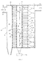
- FIG. 1 shows a hot gas cleaning system 10 comprising a barrier filter module 12 and a catalyst module 14 arranged consecutively in a housing 16.
- a hot gas inlet 18 for unclean hot gas is arranged to lead gas into unclean gas inlet space 20.
- Gas inlets 22 lead into first passageways 24 in the barrier filter module, the gas inlets being in one end of the passageways. The other end of the passageways 24, are plugged with a plug 25, thereby preventing gas from flowing directly through the passageways.
- Parallel second passageways 26 for clean gas are arranged in the barrier filter module. Passageways 26 open, at one end, into a clean gas space 28 between the barrier filter module and the catalyst module. The opposite ends of the passageways 26 are plugged with a plug 27, thereby eliminating direct connection between passageways 26 and the gas inlet space 20.
- Unclean gas flows from space 20 into first passageways 24 which are covered by a thin ceramic barrier filter layer, not shown in the figure, allowing only clean gas to flow through the filter material into adjacent second passageway 26, having a clean gas outlet 30 opening into clean gas space 28.
- Nozzles 32 are arranged in the clean gas space 28 for injecting ammonia, urea or some other additive into the gas, for e.g. reduction of NOX emissions.
- Catalyst module 14 comprises inlet passageways 34 with inlet openings 36 opening into the clean gas space 28 and outlet passageways 38 having outlet openings 40 opening into outlet conduits 42. Passageways are plugged at one end with plugs 37 and 39 respectively. Backpulsing nozzles 44 are arranged in front of the outlet conduits 42 for intermittently backpulsing cleaning gas countercurrently to the main gas stream through the catalyst filter into the clean gas side of the barrier filter.
- Funnel shaped gas outlet conduits 42 open into a clean gas housing 46 from which clean gases are guided through outlet 48 into e.g. an adjacent convection section.
- Trace medium may be introduced into the unclean gas flow through nozzles 50 at the hot gas inlet 18.
- the trace medium is separated from the gas flow in the barrier filter. Possible faults, e.g. cracks, in the barrier filter layer allow trace medium to escape into the clean gas space 28. Trace medium in the clean gas space is detected by a detector 52.
- Figure 2 shows another embodiment of the present invention, according to which the catalyst module is formed of an impermeable monolithic support structure.
- the passageways 36' are not plugged and gas is allowed to flow directly through the passageways.
- FIG. 3 shows an enlarged cross sectional view of a part of the filter module in FIG. 2 taken along line AA and FIG. 4 shows an enlarged cross sectional view of a part of the catalyst module in FIG. 2 taken along line BB.
- FIG. 3 shows the inlets 22 into the passageways 24 in the porous monolithic ceramic filter support structure, as well as, plugs 27 preventing direct connection between gas spaces 20 and 28.
- the passageways are coated with a thin porous ceramic membrane layer 45 forming the barrier layer in the filter.
- the barrier layer is about 2 to 100 ⁇ m thick, preferably about 50 ⁇ m thick.
- the pores of the porous ceramic layer are ⁇ 0.5 ⁇ m, about 0.04 to 0.5 ⁇ m, whereas the pores in the ceramic monolithic support structure are about 4 to 50 ⁇ m.
- FIG. 4 shows correspondingly the inlets 36 into the impermeable monolithic catalyst straight through passageways 34, which are coated with a catalyst layer 47.
- FIG. 5 shows an other enlarged cross sectional view of a catalyst module in which catalyst elements are connected into triangular blocks 49.
- the filter or catalyst elements may be combined in different ways to form suitable blocks which can be disconnected from the support structure.
- FIG. 6 shows a circulating fluidized bed (CFB) plant utilizing an integrated barrier filter and catalyst module system according to the present invention.
- the drawing shows a CFB system having a combustor 54, a particle separator 56, a gas passage 58 and a convection section 60.
- a hot gas (> 600°C) cleaning system 10 is arranged in the gas passage between the particle separator and the convection section.
- a filter module 12 and a catalyst module 14, are arranged in the cleaning system in a common housing 16 side by side, without substantially any free space between the modules.
- Fly ash and other particles separated in the filter module 12 are collected in a hopper 62. Separation of fly ash before catalytic reduction eliminates poisoning of the catalyst and facilitates use of a dense passageway structure for the catalyst support. The separated particles may be recirculated into the combustor or some other place in the system or may be discharged from the system.
- the flexibility of the construction allows the invention to be used for more than only one emission compound, i.e. different catalyst elements can be installed one after another in one single casing.
- the catalyst materials have to be selected so that they perform optimally in the same temperature level. It is e.g. possible to arrange a CO catalyst downstream of a N2O catalyst in casing 16.
- a DENOX catalyst module "slice" 64 for reducing NOX emissions, may be arranged in an optimal rather narrow temperature range of 340 to 370 °C, e.g. between heat transfer tube bundles in a first convection section 60 and a second convection section 66.
- Ammonia injection may preferably be divided between two stages and e.g. be injected into the particle separator and into the convection section 60.
- FIG. 7 shows another CFB system also having a combustor 54, a particle separator 56, an integrated barrier filter and catalyst module system 10, as well as, first and second convection sections 60 and 66.
- a combined monolithic filter and monolithic catalyst module system 10 is arranged between heat transfer tube bundles in the two convection sections 60 and 66 in a temperature window of about 370 to 620°C.
- a sulphur reduction is performed by means of a sorbent, such as sodium bicarbonate, introduced into the gas flow at a suitable temperature interval e.g. about 600°C, downstream of a first combined filter and catalyst module device 10.
- the sodium bicarbonate calcines in the flue gas and reacts with SO2 forming sodium sulphate.
- the sodium sulphate is separated from the gas flow in the second combined filter and catalyst module 68.
- the sorbent separated in the filter module may be recirculated for improving the utilization of the sorbent. Remaining CO and H2 is oxidized with an oxidizing catalyst in the catalyst part of the second combined filter and catalyst module 68.
Landscapes
- Chemical & Material Sciences (AREA)
- Physics & Mathematics (AREA)
- Geometry (AREA)
- Chemical Kinetics & Catalysis (AREA)
- Engineering & Computer Science (AREA)
- Environmental & Geological Engineering (AREA)
- Analytical Chemistry (AREA)
- Biomedical Technology (AREA)
- Health & Medical Sciences (AREA)
- General Chemical & Material Sciences (AREA)
- Oil, Petroleum & Natural Gas (AREA)
- Mechanical Engineering (AREA)
- General Engineering & Computer Science (AREA)
- Catalysts (AREA)
- Exhaust Gas Treatment By Means Of Catalyst (AREA)
- Filtering Of Dispersed Particles In Gases (AREA)
Abstract
Description
- This invention relates to an apparatus and a method for cleaning hot flue or process gases, and more particularly to an apparatus and a method in which flue gases are cleaned by hot gas filtration and catalytic emission reduction.
- It is known that the particulate filtration from hot gas can be performed by means of ceramic filter elements arranged in a filter vessel. The walls of the filter vessel are protected against high temperature by appropriate insulation. The filter vessel further usually comprises water cooled steel support plates for supporting the filter elements. The construction is thereby heavy and space consuming. The ratio of filtrate volume flow to filtration area of conventional ceramic filters is low and therefore makes the use of these filters economically unjustified especially for hot gas cleaning in atmospheric conditions.
- Reduction of pollutant gaseous emissions can be done by means of the Selective Catalytic Reduction (SCR) method or Selective Noncatalytic Reduction (SNCR) method. Both methods being utilized especially for NOx reduction. Typical NOx emissions from coal combustion, where staged air injection and SNCR, e.g. ammonia or urea injection, is utilized, are in the range of 50 to 60 ppm.
- The SCR systems are being utilized to reduce NOx emissions from oil and gas firing applications, in which the initial NOx concentration in the flue gases can be much higher than in coal combustion, e.g. 500 to 1000 ppm. As the level of permitted NOX emission rates decreases may SCR also be utilized for further lowering the NOX emissions in pulverized combustion of solid fuels. In these systems the catalyst, e.g. V₂O₅/TiO₂ or zeolite, is typically attached as a thin layer on a honeycomb type support structure. The flue gas flows through the passageways of the honeycomb elements or "cells" and NO is being reduced by e.g. ammonia in presence of the catalyst surface.
- Such honeycomb elements need to be changed in certain intervals in order to replace the poisoned catalyst elements with new ones. The catalysts may be poisoned by various gaseous or ash components, e.g. alkali- or As-compounds. The dimensions of the passageways in such catalyst elements depend on how clean the gas to be cleaned is, i.e. free of dust and gaseous impurities. In gas and oil combustion, very dense gridded passageways can be used, whereas dusty gas from solid fuel combustion needs wider channels, and hence a large volume requirement for the catalyst honeycomb system.
- It is e.g. known from European patent application EP 470659 to clean gas in a catalytic filter. The filter consists of a ceramic support and catalytic substance. The filter elements may be porous sintered elements in the form of filter candles. The filter elements are doped with a catalytic substance. Dust and gaseous organic compounds in hot gases can be removed with these catalytic filters simultaneously. A drawback in this gas cleaning system is that the entire catalyst filter elements have to be replaced by regenerated or new filter elements when either the filter part is made non-operative, by plugged pores, or the catalyst material is poisoned, by trace compounds, heavy metals, such as As, or alkaline deposition, or by some other reason.
- Multiple-passageway porous monolithic cross-flow filters are known from US patent 4,781,831. These filters have a large amount of filtration surface area relative to the volume of the device and consequently provide a compact filtration device. The filtration device further utilizing effectively the multiple-passageways, provides a low pressure drop flow path for the filtrate. These monolithic filters can also be used as a membrane support for membrane devices. Such membranes can include separation barriers suitable for e.g. cross-flow microfiltration, ultrafiltration and gas separation. US patent 4,983,423 shows a method for forming a porous membrane on such a membrane support.
- It is an object of the present invention to provide an improved method and apparatus for cleaning flue gases from combustors or the like, according to which catalyst poisoning is minimized and replacement of catalyst elements is readily done without the need to replace other gas cleaning elements.
- It is a further object of the present invention to provide an improved method and apparatus for cleaning flue gases, according to which filtration of flue gases is improved and replacement of filter elements can be easily done without the need to replace other gas cleaning elements.
- It is also an object of the present invention to provide an improved integrated filtration and catalyzing device for cleaning hot flue gases which can be constructed in modules.
- It is further an object of the present invention to provide a compact hot gas cleaning system, in which catalyst life is extended.
- It is still further an object of the present invention to provide a compact gas cleaning system in which filters and catalysts or parts thereof can be cleaned separately.
- According to the present invention, the above described objects are achieved by a cleaning method in which flue gases are first cleaned in a barrier filter module, formed of a monolithic ceramic filter support structure coated with a thin porous ceramic layer, the pores of the ceramic layer being typically 0.04 to 0.5 µm and thereafter in a catalyst module, formed of a support structure coated with catalyst, and arranged downstream of the barrier filter module.
- There is according to the present invention further provided an apparatus for cleaning flue gases. The apparatus comprises at least one barrier filter module, a catalyst module and means for leading gas from the barrier filter module to the catalyst module. The barrier filter module is formed of a monolithic ceramic filter support structure coated with a thin porous ceramic layer. The pores of the ceramic layer are preferably in the range of about 0.04 to 0.5 µm, the ceramic layer thereby forming a barrier filter. The catalyst module is formed of a support structure coated with catalyst material.
- According to the present invention porous honeycomb monolithic ceramic elements are utilized as supports for ceramic filter membrane attached on the honeycomb elements for removing particulates from hot flue or process gases. These monolithic ceramic support elements having a high surface area and being made of relatively low cost materials they are widely used as catalyst support for automotive catalytic converters. The monoliths may be extruded in a variety of configurations and are commercially available.
- The monoliths have a multiplicity of passageways or "cells", which are uniformly spaced throughout the support structure and extend from an inlet end face to an opposing outlet end face. Gas flowing through the monolithic filter first flows into the passageways and thereafter perpendicularly to the passageways through the ceramic material forming the filter. The passageway may have a round, square, triangular or any other suitable cross-section. The monoliths can have tens to thousands of passageways extending through them. In support structures the cell "density" usually varies between 25 to 1400 cells per square inch of the cross section of the monolith.
- Monolithic ceramic filter support structures may be fabricated from different porous ceramics, such as cordierite, alumina, mullite, silica, zirconia, silicon carbide and the mixtures thereof, cordierite being the most commonly used material. Depending on the specific ceramic material, porosity of the support structure can be all the way from below 30% to over 50%. The porosity is, however, in most cases preferably > 30 % most preferably between 30 and 50%. The mean pore size in the monolithic filter support is in the order of about 4 to 50 µm.
- In the monolithic ceramic filter used for removal of fine particles, according to the present invention, the inlet side of the monolithic ceramic filter support is covered with a fine porous ceramic membrane coating, forming a barrier filter on the support structure. The thickness of the barrier filter membrane may be about 2 to 100 µm, preferably about 50 µm. The pore size of the ceramic layer is approximately 100 fold finer than that of the monolithic support, the pore size being preferably in the range between 0.04 to 50 µm.
- As the inlet side of the passageways in the monolithic ceramic filter support structure is covered by the membrane coating, the pores of the support structure itself do not become plugged by particulate matter during filtration. The pore size in the ceramic membrane coating being much smaller than that in the support structure, the retention efficiency of the filter module will be mainly determined by the membrane pore size.
- The filter module according to the invention will therefore function as a high-temperature barrier filter, having a very low pressure drop, preferably < 400 mbar in pressurized systems and optimally < 100 mbar in atmospheric systems. The filtration velocity through the barrier filter varies typically within the range of 1 to 5 cm/s.
- For the catalyst module support structure, according to the invention, both porous or impermeable elements are commercially available. In porous type support structures, in which the gas flows through a porous wall from a gas inlet passageway to a gas outlet passageway, the pores of the support structure are coated with catalyst material and the gas contacts the catalyst while flowing through the porous walls. In the impermeable type support structure only the passageways themselves are coated with the catalyst and the NOx reduction takes place as the gas contacts the passageway walls.
- In an apparatus according to the present invention both support structures, the filter module support and the catalyst module support, may be of the porous type and preferably have the same cross sectional dimensions. Consequently also the gas flow through both support structures will then have essentially the same velocity. If, however, the catalyst module structure is of the impermeable type and gas is allowed to flow directly through all passageways, whereas the gas in the porous filter elements has to flow through a porous wall from one passageway into another, then the gas velocity in the catalyst passageways will be about 50 % of the gas velocity in the filter passageways.
- An identical casing, e.g. honeycomb type, can be used for both support elements. The length of the filtration section and the catalyst section can of course be different, since they will be defined by the surface area requirement for on the one hand the filter and on the other hand the catalyst. The cross section of the filter and catalyst elements can be circular, square or triangular or any other suitable form.
- The filter and catalyst modules, preferably in honeycomb casings, can be arranged in compartments from which the modules or parts of them can be easily withdrawn for maintenance. Two or more filter modules can be arranged on top of each other or side by side in a common compartment or in separate compartments. The present invention thereby provides a very flexible overall gas cleaning system, in which damaged, dirty or otherwise inoperative modules easily can be replaced by regenerated or new modules.
- Two different catalyst modules for reduction of two different types of emissions may also be arranged consecutively in the gas flow, whereby gas e.g. is first cleaned of N₂O and thereafter of CO.
- According to the present invention the monolithic membrane barrier filter module and the monolithic catalyst module can be arranged in a very compact configuration side by side in one single casing, without any noticeable space between the modules. Due to the small overall size and compact construction of the apparatus, the filter elements can easily be removed from the process gas stream for maintenance.
- The filter and catalyst modules may according to another embodiment of the present invention be arranged in a configuration which leaves a short space between the modules. This enables an additional feature of the invention, according to which means for additive injections are arranged in the space between the filter and catalyst sections. This combination may be utilized as a SCR system for reducing NOx emissions. Ammonia or urea is injected downstream of the filter, into a clean gas, whereby decomposition of the ammonia due to fly ash or other fine dust is prevented. In prior art systems ammonia is injected upstream of combined catalyst filters, whereby ammonia decomposes when penetrating through the particulate layer, e.g. ash layer, accumulated on hot filter surfaces. The present invention provides a new method in which the ammonia requirement is reduced.
- Cleaning of an filter module apparatus according to the present invention can be carried out by means of pulse jetting, reverse gas flow or vibrations (mechanical or acoustic). The filter modules can be cleaned periodically by high pressure, > 1 bar, with a cleaning gas system designed to inject gas intermittently for selected duration countercurrently into the main gas stream. The pressure of the cleaning gas is typically 2 to 3 times the system pressure, e.g. 3 to 6 bar in atmospheric systems and 2 to 3 times the pressure in pressurized systems. Thermal shocks in the filter and cracking may be prevented by injecting the cleaning gas pulses through the catalyst modules, in which the cleaning gas may be efficiently preheated.
- For failure detection, the filter can be equipped with an injection system for a trace medium (gas, dust, etc.) to the dusty side. By using a suitable detector (visual, optical, etc.), a fault can be located from the clean side.
- The on-line fault detection and the possibility to withdraw a filter or catalyst module or compartment on-line from the gas stream provides an easy possibility to substitute a broken filter element with a new one or only blinding the faulty element in the compartment.
- The invention provides following advantages:
- a compact construction, which provides a possibility to integrate the hot gas filter and the catalyst module system with the convection section of a boiler system. Additionally heat may thereby be recovered from hot separated ash with heat transfer surfaces in the filter section;
- low pressure drop over the integrated filter and catalyst module system, whereby two or more systems may be arranged in the gas flow without increasing the fan power requirement too much;
- the catalyst module is not easily plugged as clean gas is introduced therein and a dense honeycomb support structure may be used, which leads to low equipment volume;
- catalyst poisoning by ash is eliminated resulting in extended catalyst life;
- the monolithic ceramic filter and the catalyst elements can be constructed in modules inserted in a honeycomb support structure, the filter and the catalyst modules having the same cross section. Separate modules may easily be removed for maintenance or replaced with new ones independently;
- ammonia may be injected between the filter element and the catalyst element;
- catalyst element may be used for preheating backpulsing gas used for cleaning the filter element;
- heat transfer surfaces after the integrated filter/catalyst system, in e.g. the convection section, remain clean, no sootblowing is needed;
- the absence of erosive particles in the gas flow after the integrated filter/catalyst system allows the convection section to be designed for higher gas velocities resulting in higher heat transfer coefficient, and smaller heat transfer surfaces;
- the fouling tendency of the heat transfer surfaces is minimized;
- there is no need for a bag house after the convection section.
- The invention will be described further, by way of examples, with reference to the accompanying drawings in which
- FIG. 1 is a schematic cross-sectional through a combined barrier filter and catalyst module system according to one embodiment of the present invention;
- FIG. 2 shows a part of a schematic cross-sectional through a combined barrier filter and catalyst module system according to another embodiment of the present invention;
- FIG. 3 shows an enlarged cross section of the barrier filter module shown in FIG. 2 taken along line AA;
- FIG. 4 shows an enlarged cross section of the catalyst module shown in FIG. 2 taken along line BB;
- FIG. 5 shows an enlarged cross section of a barrier filter module, corresponding to FIG. 3, according to still another embodiment of the present invention;
- FIG. 6 shows a schematic view of a circulating fluidized bed CFB plant in which a combined barrier filter and catalyst module system according to the present invention is utilized for cleaning flue gases; and
- FIG. 7 shows a schematic view of a second CFB plant utilizing another embodiment of the present invention.
- FIG. 1 shows a hot
gas cleaning system 10 comprising abarrier filter module 12 and acatalyst module 14 arranged consecutively in ahousing 16. Ahot gas inlet 18 for unclean hot gas is arranged to lead gas into uncleangas inlet space 20.Gas inlets 22 lead intofirst passageways 24 in the barrier filter module, the gas inlets being in one end of the passageways. The other end of thepassageways 24, are plugged with aplug 25, thereby preventing gas from flowing directly through the passageways. Parallelsecond passageways 26 for clean gas are arranged in the barrier filter module.Passageways 26 open, at one end, into aclean gas space 28 between the barrier filter module and the catalyst module. The opposite ends of thepassageways 26 are plugged with aplug 27, thereby eliminating direct connection betweenpassageways 26 and thegas inlet space 20. - Unclean gas flows from
space 20 intofirst passageways 24 which are covered by a thin ceramic barrier filter layer, not shown in the figure, allowing only clean gas to flow through the filter material into adjacentsecond passageway 26, having aclean gas outlet 30 opening intoclean gas space 28.Nozzles 32 are arranged in theclean gas space 28 for injecting ammonia, urea or some other additive into the gas, for e.g. reduction of NOX emissions. -
Catalyst module 14 comprisesinlet passageways 34 withinlet openings 36 opening into theclean gas space 28 andoutlet passageways 38 havingoutlet openings 40 opening intooutlet conduits 42. Passageways are plugged at one end with plugs 37 and 39 respectively.Backpulsing nozzles 44 are arranged in front of theoutlet conduits 42 for intermittently backpulsing cleaning gas countercurrently to the main gas stream through the catalyst filter into the clean gas side of the barrier filter. - Funnel shaped
gas outlet conduits 42 open into aclean gas housing 46 from which clean gases are guided throughoutlet 48 into e.g. an adjacent convection section. - Trace medium may be introduced into the unclean gas flow through nozzles 50 at the
hot gas inlet 18. The trace medium is separated from the gas flow in the barrier filter. Possible faults, e.g. cracks, in the barrier filter layer allow trace medium to escape into theclean gas space 28. Trace medium in the clean gas space is detected by adetector 52. - Figure 2 shows another embodiment of the present invention, according to which the catalyst module is formed of an impermeable monolithic support structure. The passageways 36' are not plugged and gas is allowed to flow directly through the passageways.
- The filter and catalyst elements are combined into
square blocks 41 bypartition walls 43, each block having 4 x 4 = 16 filter and catalyst passageways, as can be seen in FIG. 3 and 4. FIG. 3 shows an enlarged cross sectional view of a part of the filter module in FIG. 2 taken along line AA and FIG. 4 shows an enlarged cross sectional view of a part of the catalyst module in FIG. 2 taken along line BB. - FIG. 3 shows the
inlets 22 into thepassageways 24 in the porous monolithic ceramic filter support structure, as well as, plugs 27 preventing direct connection betweengas spaces ceramic membrane layer 45 forming the barrier layer in the filter. The barrier layer is about 2 to 100 µm thick, preferably about 50 µm thick. The pores of the porous ceramic layer are < 0.5 µm, about 0.04 to 0.5 µm, whereas the pores in the ceramic monolithic support structure are about 4 to 50 µm. - FIG. 4 shows correspondingly the
inlets 36 into the impermeable monolithic catalyst straight throughpassageways 34, which are coated with acatalyst layer 47. - FIG. 5 shows an other enlarged cross sectional view of a catalyst module in which catalyst elements are connected into triangular blocks 49. The filter or catalyst elements may be combined in different ways to form suitable blocks which can be disconnected from the support structure.
- FIG. 6 shows a circulating fluidized bed (CFB) plant utilizing an integrated barrier filter and catalyst module system according to the present invention. The drawing shows a CFB system having a
combustor 54, aparticle separator 56, agas passage 58 and aconvection section 60. - A hot gas (> 600°C) cleaning
system 10 according to the present invention is arranged in the gas passage between the particle separator and the convection section. Afilter module 12 and acatalyst module 14, are arranged in the cleaning system in acommon housing 16 side by side, without substantially any free space between the modules. - Fly ash and other particles separated in the
filter module 12 are collected in ahopper 62. Separation of fly ash before catalytic reduction eliminates poisoning of the catalyst and facilitates use of a dense passageway structure for the catalyst support. The separated particles may be recirculated into the combustor or some other place in the system or may be discharged from the system. - The flexibility of the construction allows the invention to be used for more than only one emission compound, i.e. different catalyst elements can be installed one after another in one single casing. The catalyst materials have to be selected so that they perform optimally in the same temperature level. It is e.g. possible to arrange a CO catalyst downstream of a N₂O catalyst in
casing 16. - As an additional advantage of the present new compact catalyst configuration a DENOX catalyst module "slice" 64, for reducing NOX emissions, may be arranged in an optimal rather narrow temperature range of 340 to 370 °C, e.g. between heat transfer tube bundles in a
first convection section 60 and asecond convection section 66. Ammonia injection may preferably be divided between two stages and e.g. be injected into the particle separator and into theconvection section 60. - FIG. 7 shows another CFB system also having a
combustor 54, aparticle separator 56, an integrated barrier filter andcatalyst module system 10, as well as, first andsecond convection sections catalyst module system 10 is arranged between heat transfer tube bundles in the twoconvection sections - Due to the low pressure drop over the monolithic ceramic filter module two combined filter and
catalyst module systems 10 and 68 may be used in the CFB system without increasing the fan power requirement excessively. - According to the system shown in FIG. 3, e.g. a sulphur reduction is performed by means of a sorbent, such as sodium bicarbonate, introduced into the gas flow at a suitable temperature interval e.g. about 600°C, downstream of a first combined filter and
catalyst module device 10. The sodium bicarbonate calcines in the flue gas and reacts with SO₂ forming sodium sulphate. The sodium sulphate is separated from the gas flow in the second combined filter and catalyst module 68. The sorbent separated in the filter module may be recirculated for improving the utilization of the sorbent. Remaining CO and H₂ is oxidized with an oxidizing catalyst in the catalyst part of the second combined filter and catalyst module 68. - Comprehensive emission control systems facilitated by the invention are not intended to be limited to CFB processes, but are applicable in connection with different combustion and gasification processes, as well as for reducing pollutant emissions in gases from various chemical and metallurgical processes. Also the selection of catalysts is not intended to be limited to the ones mentioned in the examples. Development of new catalysts, and catalysts for new emission compounds, may result in deviations of the temperature windows presented in the above examples, and hence the selection of different location for the device in the gas stream.
- While the invention has been described in connection with what is presently considered to be the most practical and preferred embodiment, it is to be understood that the invention is not to be limited to the disclosed embodiment, but on the contrary, is intended to cover various modifications and equivalent arrangements included within the spirit and scope of the appended claims.
Claims (31)
- A method of cleaning hot flue or process gases utilizing a barrier filter module formed of a monolithic ceramic filter support structure coated with a thin porous ceramic layer having a pore size of about 0.04 to 0.5 microns, and a catalyst module formed of a support structure coated with catalyst, comprising the steps of:(a) passing the gas through the barrier filter module, in contact with the thin porous ceramic layer with pore size of about 0.04 - 0.5 microns, and then(b) passing the gas through the catalyst module so that there is a catalytic reaction with the gas.
- Method of cleaning gases according to claim 1, wherein the gas flow through the catalyst module and through the barrier filter module has the same velocity.
- Method of cleaning gases according to claim 1, wherein an additive such as ammonia or urea is injected into the gas flow in a space between the barrier filter and the catalyst module.
- Method of cleaning gases according to claim 1, wherein pressurized gases are cleaned in a filter module having preferably a pressure drop < 400 mbar.
- Method of cleaning gases according to claim 1, wherein atmospheric gases are cleaned in a filter module having preferably a pressure drop < 100 mbar.
- Method of cleaning gases according to claim 1, wherein a noble metal, such as platinum, rhodium or palladium, or a metal oxide, such as copper oxide, chrome oxide, manganese oxide or vanadiumpentoxide is used as catalyst for reduction of NOx, N₂O or CO, in the catalyst module.
- Method of cleaning gases according to claim 1, wherein the filter module is cleaned periodically by a high pressure cleaning gas pulse introduced countercurrently to the main gas stream.
- Apparatus for cleaning flue gases from a combustor, the apparatus comprising:
a barrier filter module, formed of a monolithic ceramic filter support structure coated with a thin porous ceramic layer, the pores of the ceramic layer being 0.04 to 0.5 µm;
a catalyst module, formed of a support structure coated with catalyst; and
means for leading flue gases to be treated from the barrier filter module to the catalyst module. - Apparatus according to claim 8, wherein the barrier filter module and the catalyst module in the gas flow have essentially the same cross sectional dimension and are arranged in honeycomb type casings.
- Apparatus according to claim 8, wherein the catalyst module is arranged immediately adjacent the barrier filter module.
- Apparatus according to claim 8, wherein the catalyst module and the barrier filter module are arranged successively in the gas flow leaving a short distance between the modules.
- Apparatus according to claim 8, wherein the pores in the ceramic filter forming the support structure for the barrier filter module are in the order of 4 to 50 µm.
- Apparatus according to claim 8, wherein the porosity of the ceramic filter forming the support structure is > 30 %.
- Apparatus according to claim 13, wherein the porosity of the ceramic filter is in the range of 30 to 50%.
- Apparatus according to claim 8, wherein the filter support structure comprises passageways arranged through the monolithic structure, the passageways being perpendicular to the gas flow through the filter and the filter comprising 25 to 1400 passageways/sq.inch of the cross section of the filter.
- Apparatus according to claim 8, wherein the porous ceramic layer in the barrier filter module is 2 to 100 µm, preferably about 50 µm thick.
- Apparatus according to claim 8, wherein a porous honeycomb cell forms the support structure for the catalyst module.
- Apparatus according to claim 8, wherein an impermeable honeycomb cell forms the support structure for the catalyst module.
- Apparatus according to claim 8, wherein the barrier filter module or the catalyst filter module are arranged in the gas flow in a compartment from which they can be withdrawn for maintenance or regeneration.
- Apparatus according to claim 8, wherein at least two barrier filter modules or at least two catalyst modules are arranged in the gas flow on top of each other.
- Apparatus according to claim 8, wherein at least two barrier filter modules or at least two catalyst modules are arranged in the gas flow side by side.
- Apparatus according to claim 8, wherein the barrier filter module and the catalyst module are arranged consecutively leaving a small space between the modules; and an injection of fluid additive for reduction of emissions is arranged in the space between the modules.
- Apparatus according to claim 8, wherein a solid additive is injected into the gas flow downstream of the barrier filter and catalyst modules; and a second barrier filter is arranged in the gas flow downstream of the injection of solid additive.
- Apparatus according to claim 8, wherein two catalyst modules coated with different catalysts are arranged consecutively in the gas flow.
- Apparatus according to claim 24, wherein the catalyst modules are arranged in the gas flow at locations having different temperatures.
- Apparatus according to claim 25, wherein the first catalyst module is arranged in the gas flow in front of a convection section and the second catalyst module is arranged after the convection section.
- A fluidized bed boiler plant, including a combustor, a particle separator, a convection section and a gas cleaning system, the gas cleaning system comprising in a common housing:
a monolithic ceramic filter support structure coated with a ceramic porous membrane, having pores < 0.5 µm; and
a monolithic catalyst support structure coated with a first catalyst arranged in the gas flow downstream of the filter support structure. - A boiler plant according to claim 27, wherein the gas cleaning system is arranged between the particle separator and the convection section.
- A boiler plant according to claim 27, wherein the gas cleaning system is arranged in the convection section between heat transfer surfaces of a first part of the convection section and a second part of the convection section at a temperature interval of < 600°C.
- A boiler plant according to claim 27, wherein a second catalyst support structure module coated with a second catalyst is arranged in the convection section downstream of the gas cleaning system.
- A boiler plant according to claim 27, further comprising a second gas cleaning system disposed in a common housing, and comprising: a monolithic ceramic filter support structure coated with a ceramic porous membrane, having pores < 0.5 µm; and a monolithic catalyst support structure coated with a catalyst arranged in the gas flow downstream of the filter support structure; said second gas cleaning system being arranged in the convection section at a temperature interval of < 400°C.
Applications Claiming Priority (2)
| Application Number | Priority Date | Filing Date | Title |
|---|---|---|---|
| US07/982,696 US5318755A (en) | 1992-11-30 | 1992-11-30 | Method and apparatus for cleaning flue gases |
| US982696 | 2001-10-17 |
Publications (2)
| Publication Number | Publication Date |
|---|---|
| EP0600440A2 true EP0600440A2 (en) | 1994-06-08 |
| EP0600440A3 EP0600440A3 (en) | 1994-10-19 |
Family
ID=25529420
Family Applications (1)
| Application Number | Title | Priority Date | Filing Date |
|---|---|---|---|
| EP9393119281A Ceased EP0600440A3 (en) | 1992-11-30 | 1993-11-30 | Method and apparatus for cleaning flue gases. |
Country Status (6)
| Country | Link |
|---|---|
| US (1) | US5318755A (en) |
| EP (1) | EP0600440A3 (en) |
| JP (1) | JPH07764A (en) |
| CA (1) | CA2110198C (en) |
| DE (1) | DE600440T1 (en) |
| ES (1) | ES2068805T1 (en) |
Cited By (13)
| Publication number | Priority date | Publication date | Assignee | Title |
|---|---|---|---|---|
| EP0709127A1 (en) * | 1994-10-25 | 1996-05-01 | Mitsubishi Jukogyo Kabushiki Kaisha | Denitration apparatus for a coal-fired boiler |
| DE19715244A1 (en) * | 1997-04-12 | 1998-10-15 | Abb Research Ltd | Cleaning high temperature propellant for gas turbines |
| US6117405A (en) * | 1997-06-20 | 2000-09-12 | Von Roll Umwelttechnik Ag | Process for removing nitrogen oxides from flue gases |
| EP1112772A1 (en) * | 1999-12-28 | 2001-07-04 | Nippon Shokubai Co., Ltd. | Process for disposing of exhaust gases |
| WO2004001290A1 (en) * | 2002-06-20 | 2003-12-31 | Steag Encotec Gmbh | Coal-fired power station |
| FR2867091A1 (en) * | 2004-03-05 | 2005-09-09 | Lab Sa | Modular and integrated device, useful for catalytic filtration and denitrification of fumes, comprises filtration module and a denitrification module |
| BE1016189A5 (en) * | 1998-11-30 | 2006-05-02 | Denso Corp | Honeycomb structure. |
| EP1690588A1 (en) * | 2005-02-14 | 2006-08-16 | STEAG encotec GmbH | Device for separating coarse ash from a flue gas stream |
| CH702613A1 (en) * | 2010-01-25 | 2011-07-29 | Dpf Systems Ag | Diesel particulate filter. |
| US8303688B2 (en) | 2007-03-09 | 2012-11-06 | Commonwealth Scientific And Industrial Research Organization | Filter apparatus and method |
| EP2554238A1 (en) | 2011-08-05 | 2013-02-06 | Pall Corporation | Catalytic filter system |
| US9504958B2 (en) | 2012-08-17 | 2016-11-29 | Pall Corporation | Catalytic filter module and catalytic filter system comprising same |
| CN107281879A (en) * | 2017-08-25 | 2017-10-24 | 贾新奎 | A quarry high dust waste gas treatment device |
Families Citing this family (34)
| Publication number | Priority date | Publication date | Assignee | Title |
|---|---|---|---|---|
| CA2088713C (en) * | 1992-02-24 | 1999-11-16 | Hans Thomas Hug | Cleaning exhaust gases from combustion installations |
| US5465690A (en) * | 1994-04-12 | 1995-11-14 | A. Ahlstrom Corporation | Method of purifying gases containing nitrogen oxides and an apparatus for purifying gases in a steam generation boiler |
| US5453108A (en) * | 1994-05-18 | 1995-09-26 | A. Ahlstrom Corporation | Apparatus for filtering gases |
| US5743929A (en) * | 1995-08-23 | 1998-04-28 | The Boc Group, Inc. | Process for the production of high purity carbon dioxide |
| US5809645A (en) * | 1995-08-30 | 1998-09-22 | Haldor Topsoe A/S | Method for in situ installation of catalyst modules in an off-gas channel |
| EP0880992B1 (en) * | 1997-05-26 | 2004-12-15 | Kabushiki Kaisha Toshiba | Desulfurization apparatus |
| US6290757B1 (en) * | 1999-03-26 | 2001-09-18 | Ceramphysics, Inc. | Nitrogen purification device |
| US6395237B1 (en) * | 2000-02-13 | 2002-05-28 | The Babcock & Wilcox Company | Circulating fluidized bed reactor with selective catalytic reduction |
| US6821490B2 (en) * | 2001-02-26 | 2004-11-23 | Abb Lummus Global Inc. | Parallel flow gas phase reactor and method for reducing the nitrogen oxide content of a gas |
| US6663839B2 (en) | 2001-02-26 | 2003-12-16 | Abb Lummus Global Inc. | Radial flow gas phase reactor and method for reducing the nitrogen oxide content of a gas |
| US6706246B2 (en) | 2001-02-26 | 2004-03-16 | Abb Lummus Global Inc. | System and method for the selective catalytic reduction of nitrogen oxide in a gas stream |
| US20020159923A1 (en) * | 2001-02-26 | 2002-10-31 | Platvoet Erwin M.J. | Gas phase reactor and process for reducing nitrogen oxide in a gas stream |
| US6749670B2 (en) | 2001-03-26 | 2004-06-15 | Shell Oil Company | Process for trapping particulate matter in hot gas and trap therefor |
| JP4846930B2 (en) * | 2001-07-18 | 2011-12-28 | 電源開発株式会社 | Exhaust gas treatment equipment |
| WO2003068363A1 (en) * | 2002-02-12 | 2003-08-21 | Clean Diesel Technologies, Inc. | Multi-stage exhaust gas purifier |
| US7090714B2 (en) * | 2002-06-17 | 2006-08-15 | Hitachi Metals, Ltd. | Ceramic honeycomb filter |
| US6808544B1 (en) | 2003-01-29 | 2004-10-26 | Angel L. Rodriguez | Furnace exhaust filter assembly |
| JP4528153B2 (en) * | 2005-02-23 | 2010-08-18 | 日本碍子株式会社 | Method for manufacturing plugged honeycomb structure |
| JP4907970B2 (en) * | 2005-12-06 | 2012-04-04 | 日野自動車株式会社 | Particulate filter maintenance method |
| FI20065227A7 (en) * | 2006-04-10 | 2007-10-11 | Raimo Vartiainen | Method and apparatus for purifying air |
| US8142534B2 (en) * | 2006-12-20 | 2012-03-27 | Tk Holdings, Inc. | Gas generating system |
| ES2304228B1 (en) * | 2008-01-23 | 2009-07-27 | Filtros Repuestos Y Servicios, S.L. | AIR FILTRATION SYSTEM AT THE EVACUATION OUTPUT OF THE BOILER OF AN ELECTRICAL POWER STATION. |
| US20090249952A1 (en) * | 2008-04-03 | 2009-10-08 | Corning Incorporated | Method and system for sorption of liquid or vapor phase trace contaminants from a fluid stream containing an electrically charged particulate |
| US20110246395A1 (en) * | 2010-02-11 | 2011-10-06 | Illinois Tool Works Inc. | Method and Apparatus For Welding Cost Calculator |
| US20110265697A1 (en) | 2010-04-29 | 2011-11-03 | Foster Wheeler North America Corp. | Circulating Fluidized Bed Combustor and a Method of Operating a Circulating Fluidized Bed Combustor |
| US8444730B2 (en) * | 2010-09-27 | 2013-05-21 | Ford Global Technologies, Llc | Even-loading DPF and regeneration thereof |
| US8309045B2 (en) | 2011-02-11 | 2012-11-13 | General Electric Company | System and method for controlling emissions in a combustion system |
| US20140170046A1 (en) * | 2011-07-29 | 2014-06-19 | Flsmidth A/S | Pollution control system for kiln exhaust |
| EP2832410B1 (en) * | 2012-03-30 | 2019-06-05 | Ibiden Co., Ltd. | Honeycomb filter and production method for honeycomb filter |
| EP2698189B1 (en) * | 2012-08-17 | 2019-08-07 | Pall Corporation | Filter module and filter system comprising same |
| JP6504314B1 (en) * | 2017-12-28 | 2019-04-24 | 中国電力株式会社 | NOx removal equipment |
| CN116635126A (en) | 2020-07-15 | 2023-08-22 | W.L.戈尔及同仁股份有限公司 | Method for filter medium regeneration and flue gas cleaning |
| CN112521986A (en) * | 2020-11-10 | 2021-03-19 | 国科永基(北京)工程安装有限公司 | High-temperature efficient explosion-proof type integrated modular dust removal equipment for pyrolysis raw gas |
| CN113144787A (en) * | 2021-02-23 | 2021-07-23 | 山东金城晖瑞环保科技有限公司 | Method for removing dust of high-temperature salt-containing flue gas by using ceramic film dust remover |
Family Cites Families (17)
| Publication number | Priority date | Publication date | Assignee | Title |
|---|---|---|---|---|
| DE2257968C3 (en) * | 1972-11-27 | 1980-11-13 | Degussa Ag, 6000 Frankfurt | Device for cleaning exhaust gases from diesel engines |
| US3978193A (en) * | 1974-01-29 | 1976-08-31 | Gould Inc. | Method and apparatus for treating exhaust gases |
| US4134733A (en) * | 1975-07-09 | 1979-01-16 | Deutsche Gold- Und Silber-Scheideanstalt Vormals Roessler | Apparatus for treatment of exhaust gases |
| CA1092910A (en) * | 1976-07-27 | 1981-01-06 | Ko'hei Hamabe | Boiler apparatus containing denitrator |
| US4455180A (en) * | 1981-08-24 | 1984-06-19 | Corning Glass Works | Method of fabricating a sintered and selectively plugged honeycomb structure |
| US4390355A (en) * | 1982-02-02 | 1983-06-28 | General Motors Corporation | Wall-flow monolith filter |
| DE3430870A1 (en) * | 1984-08-22 | 1986-02-27 | Didier Engineering Gmbh, 4300 Essen | METHOD FOR EXHAUST GAS PURIFICATION |
| JPS61238304A (en) * | 1985-04-17 | 1986-10-23 | Ngk Insulators Ltd | Ceramic filter and its preparation |
| US4956162A (en) * | 1986-06-16 | 1990-09-11 | Electric Power Research Institute, Inc. | Process for removal of particulates and SO2 from combustion gases |
| US4781831A (en) * | 1986-12-19 | 1988-11-01 | Goldsmith Robert L | Cross-flow filtration device with filtrate flow conduits and method of forming same |
| JPH03101812A (en) * | 1987-12-09 | 1991-04-26 | Yoshio Kobayashi | Method for dry-purifying waste gas |
| JPH077096B2 (en) * | 1988-04-22 | 1995-01-30 | 日本碍子株式会社 | Exhaust gas recombiner |
| US4983423A (en) * | 1988-05-24 | 1991-01-08 | Ceramem Corporation | Method of forming a porous inorganic membrane on a porous support using a reactive inorganic binder |
| US4925633A (en) * | 1988-07-25 | 1990-05-15 | The Babcock & Wilcox Company | Combined catalytic baghouse and heat pipe air heater |
| DE3920844A1 (en) * | 1989-06-24 | 1991-01-10 | Daimler Benz Ag | Monolithic ceramic element for use as soot filter - comprising segments split into sections sepd. by expansion gaps filled by binder |
| DE3923985C1 (en) * | 1989-07-20 | 1990-06-28 | Daimler-Benz Aktiengesellschaft, 7000 Stuttgart, De | |
| US5052178A (en) * | 1989-08-08 | 1991-10-01 | Cummins Engine Company, Inc. | Unitary hybrid exhaust system and method for reducing particulate emmissions from internal combustion engines |
-
1992
- 1992-11-30 US US07/982,696 patent/US5318755A/en not_active Expired - Lifetime
-
1993
- 1993-11-29 CA CA002110198A patent/CA2110198C/en not_active Expired - Fee Related
- 1993-11-30 JP JP5300195A patent/JPH07764A/en active Pending
- 1993-11-30 ES ES93119281T patent/ES2068805T1/en active Pending
- 1993-11-30 DE DE0600440T patent/DE600440T1/en active Pending
- 1993-11-30 EP EP9393119281A patent/EP0600440A3/en not_active Ceased
Cited By (18)
| Publication number | Priority date | Publication date | Assignee | Title |
|---|---|---|---|---|
| US5687656A (en) * | 1994-10-25 | 1997-11-18 | Mitsubishi Jukogyo Kabushiki Kaisha | Denitration apparatus for a caol-fired boiler |
| EP0709127A1 (en) * | 1994-10-25 | 1996-05-01 | Mitsubishi Jukogyo Kabushiki Kaisha | Denitration apparatus for a coal-fired boiler |
| DE19715244A1 (en) * | 1997-04-12 | 1998-10-15 | Abb Research Ltd | Cleaning high temperature propellant for gas turbines |
| US6117405A (en) * | 1997-06-20 | 2000-09-12 | Von Roll Umwelttechnik Ag | Process for removing nitrogen oxides from flue gases |
| BE1016189A5 (en) * | 1998-11-30 | 2006-05-02 | Denso Corp | Honeycomb structure. |
| EP1112772A1 (en) * | 1999-12-28 | 2001-07-04 | Nippon Shokubai Co., Ltd. | Process for disposing of exhaust gases |
| US6716404B2 (en) | 1999-12-28 | 2004-04-06 | Nippon Shokubai Co., Ltd. | Process for the purification of exhaust gases |
| US6994036B2 (en) | 2002-06-20 | 2006-02-07 | Steag Encotec Gmbh | Coal-fired power station |
| WO2004001290A1 (en) * | 2002-06-20 | 2003-12-31 | Steag Encotec Gmbh | Coal-fired power station |
| EP1576999A1 (en) * | 2004-03-05 | 2005-09-21 | Lab Sa | Modular and integrated device for the filtration and the catalytic denitrification of fumes, plant comprising such a device and methods for making use of them |
| FR2867091A1 (en) * | 2004-03-05 | 2005-09-09 | Lab Sa | Modular and integrated device, useful for catalytic filtration and denitrification of fumes, comprises filtration module and a denitrification module |
| EP1690588A1 (en) * | 2005-02-14 | 2006-08-16 | STEAG encotec GmbH | Device for separating coarse ash from a flue gas stream |
| US8303688B2 (en) | 2007-03-09 | 2012-11-06 | Commonwealth Scientific And Industrial Research Organization | Filter apparatus and method |
| CH702613A1 (en) * | 2010-01-25 | 2011-07-29 | Dpf Systems Ag | Diesel particulate filter. |
| EP2554238A1 (en) | 2011-08-05 | 2013-02-06 | Pall Corporation | Catalytic filter system |
| US9108134B2 (en) | 2011-08-05 | 2015-08-18 | Pall Corporation | Catalytic filter system |
| US9504958B2 (en) | 2012-08-17 | 2016-11-29 | Pall Corporation | Catalytic filter module and catalytic filter system comprising same |
| CN107281879A (en) * | 2017-08-25 | 2017-10-24 | 贾新奎 | A quarry high dust waste gas treatment device |
Also Published As
| Publication number | Publication date |
|---|---|
| ES2068805T1 (en) | 1995-05-01 |
| DE600440T1 (en) | 1995-11-09 |
| US5318755A (en) | 1994-06-07 |
| CA2110198C (en) | 1998-09-29 |
| EP0600440A3 (en) | 1994-10-19 |
| CA2110198A1 (en) | 1994-05-31 |
| JPH07764A (en) | 1995-01-06 |
Similar Documents
| Publication | Publication Date | Title |
|---|---|---|
| US5318755A (en) | Method and apparatus for cleaning flue gases | |
| RU2392456C2 (en) | Method and device for cleaning of exhaust gas | |
| EP2698188B1 (en) | Catalytic filter module and catalytic filter system comprising same | |
| US5585081A (en) | SOx, NOx and particulate removal system | |
| EP0308972B1 (en) | Apparatus and method for treating an exhaust gas from a diesel engine | |
| JP5060577B2 (en) | Dust collection element and arrangement and method for removing soot particles from exhaust gas | |
| KR100627923B1 (en) | Rolling Regeneration Diesel Particulate Trap | |
| EP1262641B1 (en) | Carbon particle reducing apparatus | |
| EP0591493B1 (en) | Apparatus and method for removing particulate deposits from high temperature filters | |
| CN111659249A (en) | Low ammonia escape desulfurization, denitrification and dust removal device | |
| US11833471B2 (en) | Catalysed filter system for treating particulate-containing exhaust gas from stationary emission sources | |
| EP3081284A1 (en) | Exhaust gas purification apparatus | |
| EP0751816B1 (en) | Treating exhaust gas from a pressurized fluidized bed reaction system | |
| EP1707774B1 (en) | Particulate matter-containing exhaust emission controlling filter, exhaust emission controlling method and device | |
| JP2587068B2 (en) | Apparatus for treating particulates in diesel engine exhaust gas | |
| CN212327926U (en) | Low ammonia escape desulfurization denitration dust collector | |
| JP6745813B2 (en) | Method and system for removing particulate matter from engine exhaust or process equipment | |
| EP1246684B1 (en) | Interlocked fiber fail-safe regenerator filter devices | |
| JP2001070753A (en) | Method and apparatus for regenerating a catalytic filter | |
| JP2001246209A (en) | Gas permeable body, manufacturing method thereof, and dust removing device | |
| JPS61268332A (en) | Dust removal purifying apparatus | |
| EP0573209A1 (en) | Filtration of gases | |
| WO1994021351A1 (en) | Active filters for integrated cleanup of gas streams | |
| JP2006233939A (en) | Exhaust emission control filter and device | |
| JPH01245819A (en) | Filter element, filter body and filter device |
Legal Events
| Date | Code | Title | Description |
|---|---|---|---|
| PUAI | Public reference made under article 153(3) epc to a published international application that has entered the european phase |
Free format text: ORIGINAL CODE: 0009012 |
|
| 17P | Request for examination filed |
Effective date: 19931130 |
|
| AK | Designated contracting states |
Kind code of ref document: A2 Designated state(s): DE ES FR SE |
|
| PUAL | Search report despatched |
Free format text: ORIGINAL CODE: 0009013 |
|
| AK | Designated contracting states |
Kind code of ref document: A3 Designated state(s): DE ES FR SE |
|
| EL | Fr: translation of claims filed | ||
| REG | Reference to a national code |
Ref country code: ES Ref legal event code: BA2A Ref document number: 2068805 Country of ref document: ES Kind code of ref document: T1 |
|
| 17Q | First examination report despatched |
Effective date: 19950907 |
|
| DET | De: translation of patent claims | ||
| RAP1 | Party data changed (applicant data changed or rights of an application transferred) |
Owner name: FOSTER WHEELER ENERGIA OY |
|
| GRAG | Despatch of communication of intention to grant |
Free format text: ORIGINAL CODE: EPIDOS AGRA |
|
| STAA | Information on the status of an ep patent application or granted ep patent |
Free format text: STATUS: THE APPLICATION HAS BEEN REFUSED |
|
| 18R | Application refused |
Effective date: 19970321 |