EP0600115B1 - Multilayer coated hard alloy cutting tool - Google Patents
Multilayer coated hard alloy cutting tool Download PDFInfo
- Publication number
- EP0600115B1 EP0600115B1 EP92120443A EP92120443A EP0600115B1 EP 0600115 B1 EP0600115 B1 EP 0600115B1 EP 92120443 A EP92120443 A EP 92120443A EP 92120443 A EP92120443 A EP 92120443A EP 0600115 B1 EP0600115 B1 EP 0600115B1
- Authority
- EP
- European Patent Office
- Prior art keywords
- coating
- substrate material
- hard alloy
- cutting tool
- surface layer
- Prior art date
- Legal status (The legal status is an assumption and is not a legal conclusion. Google has not performed a legal analysis and makes no representation as to the accuracy of the status listed.)
- Expired - Lifetime
Links
Images
Classifications
-
- C—CHEMISTRY; METALLURGY
- C23—COATING METALLIC MATERIAL; COATING MATERIAL WITH METALLIC MATERIAL; CHEMICAL SURFACE TREATMENT; DIFFUSION TREATMENT OF METALLIC MATERIAL; COATING BY VACUUM EVAPORATION, BY SPUTTERING, BY ION IMPLANTATION OR BY CHEMICAL VAPOUR DEPOSITION, IN GENERAL; INHIBITING CORROSION OF METALLIC MATERIAL OR INCRUSTATION IN GENERAL
- C23C—COATING METALLIC MATERIAL; COATING MATERIAL WITH METALLIC MATERIAL; SURFACE TREATMENT OF METALLIC MATERIAL BY DIFFUSION INTO THE SURFACE, BY CHEMICAL CONVERSION OR SUBSTITUTION; COATING BY VACUUM EVAPORATION, BY SPUTTERING, BY ION IMPLANTATION OR BY CHEMICAL VAPOUR DEPOSITION, IN GENERAL
- C23C30/00—Coating with metallic material characterised only by the composition of the metallic material, i.e. not characterised by the coating process
- C23C30/005—Coating with metallic material characterised only by the composition of the metallic material, i.e. not characterised by the coating process on hard metal substrates
-
- C—CHEMISTRY; METALLURGY
- C23—COATING METALLIC MATERIAL; COATING MATERIAL WITH METALLIC MATERIAL; CHEMICAL SURFACE TREATMENT; DIFFUSION TREATMENT OF METALLIC MATERIAL; COATING BY VACUUM EVAPORATION, BY SPUTTERING, BY ION IMPLANTATION OR BY CHEMICAL VAPOUR DEPOSITION, IN GENERAL; INHIBITING CORROSION OF METALLIC MATERIAL OR INCRUSTATION IN GENERAL
- C23C—COATING METALLIC MATERIAL; COATING MATERIAL WITH METALLIC MATERIAL; SURFACE TREATMENT OF METALLIC MATERIAL BY DIFFUSION INTO THE SURFACE, BY CHEMICAL CONVERSION OR SUBSTITUTION; COATING BY VACUUM EVAPORATION, BY SPUTTERING, BY ION IMPLANTATION OR BY CHEMICAL VAPOUR DEPOSITION, IN GENERAL
- C23C16/00—Chemical coating by decomposition of gaseous compounds, without leaving reaction products of surface material in the coating, i.e. chemical vapour deposition [CVD] processes
- C23C16/22—Chemical coating by decomposition of gaseous compounds, without leaving reaction products of surface material in the coating, i.e. chemical vapour deposition [CVD] processes characterised by the deposition of inorganic material, other than metallic material
- C23C16/30—Deposition of compounds, mixtures or solid solutions, e.g. borides, carbides, nitrides
- C23C16/34—Nitrides
-
- C—CHEMISTRY; METALLURGY
- C23—COATING METALLIC MATERIAL; COATING MATERIAL WITH METALLIC MATERIAL; CHEMICAL SURFACE TREATMENT; DIFFUSION TREATMENT OF METALLIC MATERIAL; COATING BY VACUUM EVAPORATION, BY SPUTTERING, BY ION IMPLANTATION OR BY CHEMICAL VAPOUR DEPOSITION, IN GENERAL; INHIBITING CORROSION OF METALLIC MATERIAL OR INCRUSTATION IN GENERAL
- C23C—COATING METALLIC MATERIAL; COATING MATERIAL WITH METALLIC MATERIAL; SURFACE TREATMENT OF METALLIC MATERIAL BY DIFFUSION INTO THE SURFACE, BY CHEMICAL CONVERSION OR SUBSTITUTION; COATING BY VACUUM EVAPORATION, BY SPUTTERING, BY ION IMPLANTATION OR BY CHEMICAL VAPOUR DEPOSITION, IN GENERAL
- C23C16/00—Chemical coating by decomposition of gaseous compounds, without leaving reaction products of surface material in the coating, i.e. chemical vapour deposition [CVD] processes
- C23C16/22—Chemical coating by decomposition of gaseous compounds, without leaving reaction products of surface material in the coating, i.e. chemical vapour deposition [CVD] processes characterised by the deposition of inorganic material, other than metallic material
- C23C16/30—Deposition of compounds, mixtures or solid solutions, e.g. borides, carbides, nitrides
- C23C16/40—Oxides
- C23C16/403—Oxides of aluminium, magnesium or beryllium
-
- Y—GENERAL TAGGING OF NEW TECHNOLOGICAL DEVELOPMENTS; GENERAL TAGGING OF CROSS-SECTIONAL TECHNOLOGIES SPANNING OVER SEVERAL SECTIONS OF THE IPC; TECHNICAL SUBJECTS COVERED BY FORMER USPC CROSS-REFERENCE ART COLLECTIONS [XRACs] AND DIGESTS
- Y10—TECHNICAL SUBJECTS COVERED BY FORMER USPC
- Y10T—TECHNICAL SUBJECTS COVERED BY FORMER US CLASSIFICATION
- Y10T428/00—Stock material or miscellaneous articles
- Y10T428/24—Structurally defined web or sheet [e.g., overall dimension, etc.]
- Y10T428/24942—Structurally defined web or sheet [e.g., overall dimension, etc.] including components having same physical characteristic in differing degree
- Y10T428/2495—Thickness [relative or absolute]
- Y10T428/24967—Absolute thicknesses specified
- Y10T428/24975—No layer or component greater than 5 mils thick
-
- Y—GENERAL TAGGING OF NEW TECHNOLOGICAL DEVELOPMENTS; GENERAL TAGGING OF CROSS-SECTIONAL TECHNOLOGIES SPANNING OVER SEVERAL SECTIONS OF THE IPC; TECHNICAL SUBJECTS COVERED BY FORMER USPC CROSS-REFERENCE ART COLLECTIONS [XRACs] AND DIGESTS
- Y10—TECHNICAL SUBJECTS COVERED BY FORMER USPC
- Y10T—TECHNICAL SUBJECTS COVERED BY FORMER US CLASSIFICATION
- Y10T428/00—Stock material or miscellaneous articles
- Y10T428/26—Web or sheet containing structurally defined element or component, the element or component having a specified physical dimension
- Y10T428/263—Coating layer not in excess of 5 mils thick or equivalent
- Y10T428/264—Up to 3 mils
- Y10T428/265—1 mil or less
Definitions
- the present invention relates to hard alloy cutting tools having multilayer surface coatings for providing good adhesion, wear and chipping resistance.
- the past solutions for improving the toughness of coated hard alloys involved mainly the surface layer portion of the substrate material, not the substrate material itself.
- the concept is that if the interior (core) of the hard alloys is hard, and the surface layers of the substrate material is tough, both wear resistance and chipping resistance can be improved simultaneously.
- Such materials were first disclosed in a Japanese Patent Application, First Publication, No. Sho 52(1977)-110,209, which disclosed a coated hard alloy of improved toughness as a result of having a surface layer thickness of 10-200 ⁇ m, whose hardness is lowered by 2-20 % compared with that of the core of the substrate material.
- the first embodiment shows a substrate material of a composition, WC-10 % TiC-10 % Co (by weight in all the subsequent cases, unless otherwise stated), coated with a slurry of WC-10 % Co, dried and sintered at 1430 o C for one hour to prepare a surface layer thickness of 130 ⁇ m, Vicker's hardness of 1320 in the surface layer, and 1460 in the core.
- a surface layer thickness 130 ⁇ m
- Vicker's hardness of 1320 in the surface layer Vicker's hardness of 1320 in the surface layer
- 1460 in the core.
- a chemical vapor deposited (CVD) TiC coating of a 6 ⁇ m thickness is provided on the Co-enriched surface layer, thereby producing a coated high toughness hard alloy.
- a TiC coated hard alloy in which a mixture consisting of WC-6 % Co and WC-10 % Co is press, compacted and sintered to produce a substrate material having a surface layer thickness of 80 ⁇ m, and Vicker's hardness of 1320, and a core Vicker's hardness of 1450.
- the embodiments of the Japanese Patent Application, First Publication No. Sho 53(1978)-131,909 involves a sintered hard alloy having a Co surface coating, to produce a sintered hard alloy with a Vicker's hardness of 1050 at the surface.
- Another embodiment of the above-noted patent application involves the steps of preparing the mixture, a first sintering, coating the surface with graphite and a second sintering, to produce a toughness substrate material having a Vicker's hardness of 1160 at the surface.
- the first embodiment of the above-noted patent discloses a sintered hard metal, produced from a powdered mixture consisting of WC-4 % (Ti 0.75 W 0.25 )(C 0.68 N 0.32 )-5 % (Ta 0.75 Nb 0.25 )C-5.5 % Co, and by heating the mixture in a 0.1333 Pa (1X10 -3 torr) vacuum at 1450 °C to eliminate the B-1 type hard phase completely to a depth of 10 ⁇ m, so that the surface layer is virtually all WC-Co.
- the surface of the substrate material is coated with a 6 ⁇ m thick CVD TiC coating to produce a coated hard alloy cutting tool.
- the toughness of this tool is high because the surface layer becomes enriched with Co as the B-1 type hard phase is eliminated.
- Prior art document WO-A-09205009 discloses a coated cemented carbide covered by hard layers by means of a CVD method as well as a PCD method, wherein the cemented carbide has a Co-rich layer of less then 50 ⁇ m thickness and a Co content of 125 to 300 % of that of the bulk substrate cobalt concentration.
- a cemented carbide of A and B type porosity having a Co-rich layer was used as a substrate.
- U.S. Pat. 4,610,931 discloses a coated hard alloy similar to the coated hard alloy disclosed in U.S. Pat. 4,277,283.
- This patent further discloses the following: hard alloys containing no free carbon particles in which a rake surface is removed by grinding and re-treated with heat to covert the nitrides and carbonitrides in the surface layer to carbides; a Co-enriched surface hard alloy; and the above-treated and coated hard alloy.
- the first embodiment of this patent shows a material WC-10.3 % TaC-5.85 % TiC-0.2 % NbC-8.5 % Co-1.5 % TiN, which is heated at 1496 °C for 30 minutes; sintered in a vacuum; made into a cutting insert after which the upper and lower surfaces (rake surfaces) are ground; heated again at 1427 °C for 60 minutes in a vacuum at 13.33 Pa (100 ⁇ m Hg), and after cooling at a given rate to 1204 °C, the flank surface is ground.
- the surface is coated with TiC and TiN coatings using the usual CVD coating method to produce coated hard alloys having no free carbon particles, and having a Co-enriched layer and no B-1 type hard phases to a depth of 22.9 ⁇ m, and coated with a multilayer consisting of 5 ⁇ m thick TiC, 3 ⁇ m thick TiCN and 1 ⁇ m thick TiN layers.
- the first embodiment of the above-noted patent discloses a method of producing a substrate material by the following steps : preparing compacts of a powder mixture of WC-5 % TiC-7 % Co: sintering the compacts at 1380 °C for one hour; carburizing at 1330 °C for 10 minutes in an atmosphere of a 2.67 x 10 3 Pa (20 torr) 80 % H 2 -20% CH 4 mixture; decarburizing at 1310 °C for 2 minutes in an atmosphere of 1.33 x 10 3 Pa (10 torr) 90 % H 2 -10 % CO 2 mixture; and cooling in a vacuum; thereby obtaining a microstructure having a Co content which is highest at. the surface and gradually decreases towards the core Co content.
- the substrate material prepared in this manner is coated with a CVD TiC coating of a 5 ⁇ m thickness.
- the Co-enriched surface layer of the hard alloy cutting tool according to U.S.Pat. 4,830,930 has a Co content 2.2 times greater than the average Co content of the core.
- the third embodiment of the above-noted patent discloses, a hard alloy comprising a surface and an inner portion, characterized in that the concentration of the Co-enriched layer is highest (relative Co content is 380 %) at the outermost surface of the body and approaches the concentration of the inner portion.
- a coated hard alloy material with a Co-enriched surface layer having 2 ⁇ m of TiC, 2 ⁇ m of TiCN and 2 ⁇ m of TiN produced according to the chemical vapor deposition method.
- the hard alloy cutting tool according to U.S. Pat. 4,830,930 discloses a coated hard alloy material having a Co-enriched surface on which the first coating of TiC is deposited.
- This hard alloy cutting tool is deficient in that the wear resistance is inadequate due to inter-diffusion of WC and Co from the surface layer into the first TiC coating.
- the reason recited for using the first layer of TiC is that when TiC is applied directly to the Co-enriched surface layer, alloying occurs in the enriched layer.
- U.S. Pat. 4,911,989 discloses a surface-coated and cemented carbide substrate in which the hardness of the cemented carbide substrate, in the range of 2-5 ⁇ m from the interface between the coating layer and substrate, is 700-1300 kg/mm 2 by Vicker's hardness (claim 1). The above noted hardness is less than on the inside of the cemented carbide substrate.
- the cemented carbide substrate wherein the quantity of the Co in the cemented carbide substrate, in the range of 2-20 ⁇ m to 50-100 ⁇ m from the interface, is 1.5 to 7 times by weight greater than the average quantity of the Co (claim 5).
- the fourth embodiment shows a substrate material made of a powdered mixture, WC-2 % TiCN-3 % TaC-5.6 % Co, which is heated in a vacuum to 1400 °C, held for 30 minutes and is sintered in a N 2 atmosphere at 266.6 Pa (2 torr), cooled, to 1320 °C at a cooling rate of 10 °C/min, and then cooled to 1200 °C in a vacuum of 0.133 Pa (1 X 10 -3 torr) at a cooling rate of 1 °C/min, to produce a cemented carbide substrate interface where the quantity of the Co is 3 to 7 times, by weight greater than the average quantity of the Co.
- the first embodiment concerns the surface coating of a cemented carbide substrate with the usual CVD TiC coating to this is of 5 ⁇ m thick and Al 2 O 3 coating that is 5 ⁇ m thick.
- the fifth embodiment concerns the surface coating of a cemented carbide substrate with the usual CVD coating TiC (3 ⁇ m)/TiN (2 ⁇ m)/TiC (1 ⁇ m)/Al 2 O 3 (1 ⁇ m).
- the seventh embodiments concern the surface coating of a cemented carbide substrate with the usual CVD coating TiC (5 ⁇ m)/Al 2 O 3 (1 ⁇ m).
- U.S.Pat. 4,497,874 discloses a coated hard alloy material having a Co-enriched surface on which a first coating of TiN is deposited.
- the reason recited for using the first layer of TiN instead of the usual coating of TiC is if TiC coating is applied directly to the Co-enriched surface layer, alloying occurs in the enriched layer. Therefore, the first TiN coating is used to prevent such alloying, and to form a thick layer of TiC without resorting to forming a gradation layer.
- a method for preparing a substrate material of WC-6 % TaC-6 % Co-5 % (W 0.5 Ti 0.5 )C according to the following steps: preparing pressed compacts and dewaxing at 1260 o C; heating the dewaxed compacts in a N 2 atmosphere and flowing rate of 3 1/min for 45 minutes; removing the nitrogen and raising the temperature to 1445 o C, and sintering the compacts for 100 minutes; to produce a substrate material having a Co-enriched 30 ⁇ m thick surface layer in which there is no B-1 type hard phase.
- the hard alloys are produced by coating the substrate material with TiN/TiC/TiN or with Al 2 O 3 .
- U.S.Pat. 4,812,370 discloses in the claims, a coated hard alloy having a Co-enriched surface layer on which a WC and Co-diffused TiC first coating is deposited, a TiCN/TiN second coating to prevent the diffusion of WC and Co, a third coating of pure TiC, and a fourth coating, such as TiCO, TiCNO and Al 2 O 3 .
- a coated hard alloy material of WC-12.4 % (Ti 0.46 Ta 0.22 W 0.32 )(C 0.80 N 0.20 )-8.0 % Co having a Co-enriched surface layer of an 18 ⁇ m thickness, and having a 3 ⁇ m thick TiC coating with diffused WC and Co, 2 ⁇ m of TiCN, 2 ⁇ m TiC and 0.3 ⁇ m Al 2 O 3 coating.
- the foregoing technologies are aimed at solving the problems of the chipping of hard alloys when a CVD coating is applied directly to the Co-enriched surface layer of a substrate material, causing the formation of undesirable microstructures such as pores and a brittle eta phase in the surface layer, due to the diffusion of WC and Co from the substrate.
- the TiC coatings with diffused WC and Co also suffer from poor wear resistance.
- the present invention presents a new technology for preparing a coated hard alloy cutting tool of high toughness and high resistance to wear and chipping.
- the objective of the present invention is to present a coated hard alloy cutting tool of high toughness and high resistance to wear and chipping, in which the surface layer of the substrate material is free of pores and a brittle phase, and is adhered tightly to the coatings applied thereon.
- the present invention is as defined in claim 1 and concerns a coated hard alloy cutting tool comprising a plurality of hard coatings formed on the surfaces of a primarily WC substrate material containing Co, and consisting essentially of a core and multiple surface layers.
- a Co-enriched surface layer occurs within a surface layer region of 50 ⁇ m from an interface of said substrate material. wherein the Co content in a surface layer of 5-10 ⁇ m thickness from an interface of said substrate material is within a range from 15-25 % by weight, wherein the Co content in said surface layer is more than the Co content in said core, wherein the content of the carbides of Ti, Ta, and Nb is lower than that in said core, and wherein the plurality of surface coatings consist of a primary coating of TiCN deposited on the surface layer, a secondary coating of Al 2 O 3 deposited on the primary coating, and a surface coating consisting of at least one coating of TiCN and TiN deposited on the secondary coating of Al 2 O 3 , and optionally a first intermediate coating (16) between the surface of the WC substrate (12) and said primary coating (13) and a second intermediate coating (17) between said primary coating (13) and said secondary coating (14)
- a surface region within a distance of 100 ⁇ m to 400 ⁇ m from said interface between coatings and substrate material is substantially free of said free carbon particles, while free carbon particles are present in a region of said core located beyond 100-400 ⁇ m from said interface of said substrate material.
- the Co content in a region of said core located substantially beyond 100 ⁇ m depth from said interface of said substrate material is within the range from 4-8 % by weight.
- the proportion of a carbide of Ti, Ta and Nb at the surface layer of 5-10 ⁇ m thickness from said interface of said substrate material is lower than that in the core portion at a depth of 100 ⁇ m of said substrate material.
- the coatings of the present invention are deposited at relatively low temperatures, and a relatively high concentration of Co in the surface layers. Therefore, compared with the existing coated cutting tools, residual tensile stresses in the as-deposited coating layers are held relatively low, between not more than 20 Kg/mm 2 .
- the low residual stress level in the coatings is a reason for high chipping resistance of the cutting tools of the present invention.
- the interface (which is also the internal surface of the substrate material) between the substrate material and the primary coating of TiCN is provided with a first intermediate coating of TiN to lower the residual stress of the primary coating of TiCN.
- the thickness of the first intermediate coating of TiN (between the substrate interface and the primary coating TiCN) is also preferably less than 1 ⁇ m.
- a second intermediate coating consisting of at least one layer of a TiC layer, TiCO layer or TiCNO layer, is provided so as to improve the adhesion of the coatings.
- the thickness of the second intermediate coating of TiCO or TiCNO layer that are preferably less than 1 ⁇ m thickness.
- the coated hard alloy cutting tool that has coated directly on the surface of the substrate material will still poor adhesion between the coating layer and the substrate material. Accordingly, a barrel finishing, a shot blasting and/or acid dipping is applied to the surface of the substrate material after sintering, to solve the above noted problem.
- the chipping resistance is improved further in the present invention by treating the as-deposited coatings so as to adjust the magnitude and type of residual stresses in the coatings.
- the tensile residual stresses in the coating can be converted into compressive residual stresses. This is accomplished in the following way.
- Shot peening is employed in the present invention to effectively control the magnitude and type of residual stresses in the shot peened coatings and underlying coating.
- the tensile residual stress level is lowered to not more than 10 Kg/mm 2 , and by varying the peening conditions, it is possible to convert tensile stresses into compressive stresses of not more than 20 Kg/mm 2 .
- the residual tensile stresses in the primary coating can be made to be not more than 20 Kg/mm 2 .
- This value can be further controlled with the application of shot peening to not more than 10 Kg/mm 2 .
- shot peening it is even possible to convert the tensile residual stresses in the primary coating to compressive residual stresses, and to control the value of the compressive residual stresses so that it is not more than 20 Kg/mm 2 .
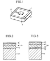
- Figure 1 is an illustration of an example of application of the present invention to making of an insert.
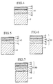
- Figure 2 is a cross sectional view of the coating configuration of a first embodiment of the insert shown in Figure 1.
- Figure 3 is a cross sectional view of the coating configuration of a second embodiment of the insert shown in Figure 1.
- Figure 4 is a cross sectional view of the coating configuration of a third embodiment of the insert shown in Figure 1.
- Figure 5 is a cross sectional view of the coating configuration of a fourth embodiment of the insert shown in Figure 1.
- Figure 6 is a cross sectional view of the coating configuration of a fifth embodiment of the insert shown in Figure 1.
- Figure 7 is a cross sectional view of the coating configuration of a sixth embodiment of the insert shown in Figure 1.
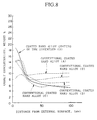
- Figure 8 shows a relationship between the Co concentration and the distance from the interface of the substrate material in some samples.
- Figure 1 is an example of applying the technique of preparing the coated hard alloy material of the invention to an insert.
- a square-shaped insert body 1 has a rake surface 2 on each of the top and bottom surfaces, and the flank surfaces 3 are formed on the side surfaces thereof, forming cutting edges 4 at the intersections of the top and bottom surface with the side surfaces.
- the insert body 1 comprises a substrate material and various coatings to be described later.
- Figure 2 is a first embodiment of the coating layer configuration of the invention.
- the coating layer 10 of this embodiment is formed on a substrate material 12, and consists of a primary coating 13, a secondary coating 14 and a surface coating 15.
- Figure 3 is a second embodiment of the coating layer configuration of the invention.
- the coating layer 20 of this embodiment is formed on the interface of the substrate material 12, and consists of a first intermediate coating 16, the primary coating 13, the secondary coating 14 and the surface coating 15.
- Figure 4 is a third embodiment of the coating layer configuration of the invention.
- the coating layer 30 of this embodiment is formed on the interface of the substrate material 12, and consists of a first intermediate coating 16, the primary coating 13, a second intermediate coating 17, the secondary coating 14 and the surface coating 15.
- Figure 5 is a forth embodiment of the coating layer configuration of the invention.
- the coating layer 40 of the embodiment is formed on the interface of the substrate material 12, and consists of the primary coating 13, the second intermediate coating 17, the secondary coating 14 and the surface coating 15.
- Figure 6 is a fifth embodiment of the coating layer configuration of the invention.
- the coating layer 50 of the embodiment is formed on the interface of the substrate material 12, and consist of the primary coating 13, the second intermediate coating 17, the secondary coating 14 and the surface coating 15.
- the second intermediate coating 17 consists of a primary intermediate coating 18 and a secondary intermediate coating 19.
- Figure 7 is a sixth embodiment of the coating layer configuration of the invention.
- the coating layer 60 of the embodiment is formed on the interface of the substrate material 12, and consist of the first intermediate coating 16, the primary coating 13, the second intermediate coating 17, the secondary coating 14 and the surface coating 15.
- the second intermediate coating 17 consists of a primary intermediate coating 18 and a secondary intermediate coating 19.
- the substrate material 12 has WC as its primary constituent, with Co added as a binder, but may contain other additives such as B-1 type hard phases comprising carbides, nitrides and/or carbonitrides of Ti, Ta and Nb containing W, and unavoidable impurities.
- the essential conditions are that the Co-enriched surface layer occurs within a surface layer region of 50 ⁇ m from an interface of said substrate material, wherein the Co content in a surface layer that is 5-10 ⁇ m thickness from an interface of said substrate material is within a range from 15-25 % by weight; wherein the Co content in said surface layer is more than the Co content in said core; and wherein the content of the carbides of Ti, Ta and Nb is lower than that in said core.
- another essential condition is that the Co content in the region of said core located beyond about 100 ⁇ m depth from said interface of said substrate material is within the range from 4-8 % by weight.
- a surface region within a distance of 100 ⁇ m to 400 ⁇ m from said interface between coatings and substrate material is substantially free of said free carbon particles, while free carbon particles are present in a region of said core located beyond 100-400 ⁇ m from said interface of said substrate material.
- the primary coating 13 is composed of a TiCN layer
- the secondary coating 14 is composed of a Al 2 O 3 layer
- the surface coating 15 is composed of either or both of a TiCN layer and a TiN layer.
- the first intermediate coating 16 is composed of a TiN layer and the second intermediate coating is composed of at least one of the layers of TiC, TiCO and TiCNO.
- a powder mixture corresponding to the desired composition of the substrate material 12 is prepared. This powder mixture is mixed with binders and additives, as necessary, and the mixture is ball-milled and dried to obtain a powder material.
- the powder material which can be used in preparing the raw material includes any one or a plurality of the elements in Group 4a, Group 5a and Group 6a; or carbides, nitrides and carbonitrides of Group 4a, Group 5a and Group 6a elements as well as other known elements or compounds generally used in hard alloy materials, such as powdered materials of WC, (W,Ti)C, (Ta,Nb)C, Co and graphite.
- the powdered material is press compacted into green compacts, which are sintered in a reduced pressure furnace at around 1400 o C to produce a substrate material which has a core that contains free carbon particles but whose surface layer of 100-400 ⁇ m depth is substantially free of free carbon particles.
- the free carbon particles are precipitated as black particles in the body of the substrate material during carburizing, but in this invention this precipitation is controlled to occur in the core at the depth of 100-400 ⁇ m, which is referred to as the core zone.
- the precipitation depth closest point to the surface is 100 ⁇ m
- the farthest depth is 400 ⁇ m.
- the surfaces of the sintered compacts are processed by such means as honing, and CVD coatings deposited at relatively low temperature thereon to produce coated hard alloy having the surface layer with high Co content(15-25%) inserts of the invention.
- the residual stresses in the as-deposited coatings are tensile, whose value is less than 20 Kg/mm 2 .
- the residual stresses in the coatings can be adjusted by means of shot peening.
- the peening parameters By adjusting the peening parameters, the residual stresses can be lowered from tensile residual stress of 20 Kg/mm 2 to less than 10 Kg/mm 2 .
- the stress type can also be altered from a tensile to a compressive type.
- the speed is in a range of 50-70 m/s, and the peening time of 60-90 seconds to obtain the range of stresses mentioned above.
- WC powder of 3.5 ⁇ m average diameter, (W 0.58 Ti 0.42 )C powder of 1.5 ⁇ m average diameter, (Ta 0.83 Nb 0.17 )C powder of 1.4 ⁇ m average diameter, Co powder of 1.2 ⁇ m average diameter, were blended into a mixture having a composition, WC-8 % (W 0.58 Ti 0.42 )C-5.5 % (Ta 0.83 Nb 0.17 )C-5.5 % Co, all by weight, to which 0.08 % graphite powder was added, and the entire mixture was wet-milled for 72 hours in a ball-mill, and dried.
- Green pressed compacts were made in accordance with ISO CNMG120408 using a press at 15 Kg/mm 2 . The green pressed compacts were sintered in a vacuum of 1.333 Pa (1x10 -2 torr) at 1410 °C for one hour. Samples of hard alloy substrate material, which were basically free of free carbon particles were thus produced.
- This one group of samples of the hard alloy substrate material is has a denuded zone of 150 ⁇ m depth which is basically free of free carbon particles and has a core zone of over 150 ⁇ m depth which has free carbon particles when viewed under optical microscope.
- the cutting edges were prepared by honing the surface to a depth of 0.07 mm on the rake surface and to a depth of 0.04 mm on the flank surfaces.
- a substrate material was obtained in which the Ti content was 0.9 %, the Ta content was 1.6 % and the Nb content was 0.2 % at a depth 10 ⁇ m, and in which the Ti content was 2.0 %, the Ta content was 4.6 % and the Nb content was 0.5 % at a depth of 100 ⁇ m. Accordingly, the B-1 type hard phase content at the surface of said substrate material was less than the hard phase content of the internal portion of the substrate material.
- samples A shown in Table 2 were produced, according to the process disclosed in U.S.P. 4,277,283 (JPA, First Publication No. Sho 54(1979)- No.87719). These samples were produced for comparative evaluation by blending starting materials from powdered particles of: WC-6.3 % (Ti 0.75 W 0.25 )(C 0.68 N 0.32 )-7.5 % (Ta 0.75 Nb 0.25 )C-10.5 % Co, with 0.26 % graphite, and by pressing the powder to produce green pressed compacts. They were sintered at 1380 °C in a vacuum of 0.1333 Pa (1 X 10 -3 torr) to produce samples of a substrate material having essentially free carbon particles. -The samples were treated by honing and a 6 ⁇ m thick coating of TiC was deposited thereon using the same procedure as the first embodiment to produce sample A for comparative evaluation.
- the profiles of Co distribution in the surface layer of the substrate material were as shown in Figure 8, indicating that the thickness of the B-1 phase denuded zone was 19 ⁇ m and that the substrate material had essentially no Ti, Ta and Nb at the depth of 10 ⁇ m from the surface of said substrate material.
- the substrate material of this disclosed embodiment was WC-5 % TiC-7 % Co, and after blending the materials and pressing to produce green pressed compacts, they were sintered at 1380 °C for 1 hour, in a vacuum. They were then carburized in a gas mixture of H 2 (80 %)-CH 4 (20 %, by volume) at a reduced pressure of 2.67 x 10 3 Pa (20 torr), and subsequently decarburized at 1310 °C, for 2 minutes, in a gas mixture of H 2 (90 %)-CO 2 (10 %, all by volume), and cooled to room temperature in a vacuum.
- the substrate material thus produced was treated by honing and a coating of TiC was deposited by the same procedure as in the first embodiment to produce sample B with a 5 ⁇ m thick coating of TiC.
- the profile of the Co distribution was as shown in Figure 8, indicating that the B-1 type hard phase was present in the surface layer and in the core zone.
- the Ti content of the substrate material was 4.5 % by weight at a depth of 10 ⁇ m, and 5.1 % at a depth of 100 ⁇ m depth.
- coated hard alloy insert sample C was prepared in the same way as disclosed in Example 1 of U.S.Pat. 4,497,874.
- This sample for comparative evaluation was produced by mixing the starting material from powdered particles of: WC-5 % (W 0.5 Ti 0.5 )C-6 % TaC-6 % Co, with 0.08 % graphite. This mixture was then press compacted, dewaxed and sintered at 1260 °C with flowing nitrogen, at a rate of 3 l/min, at a reduced pressure of 8 x 10 4 Pa (600 torr). After 45 minutes of heating, the nitrogen was removed and sintering was performed at 1445 °C for 100 minutes in a reduced-pressure argon atmosphere of 266.6 Pa (2 torr). The surfaces of the sample were honed as before, and a multilayer coating consisting of TiN (1.5 ⁇ m)-TiC (8 ⁇ m)-Al 2 O 3 (2 ⁇ m).
- the thickness of the B-1 phase denuded zone was 28 ⁇ m, and the presence of free-carbon particles was noted. This sample had essentially no Ti, Ta at a depth of 10 ⁇ m.
- sample D was produced for comparative evaluation in accordance with the first embodiment in the U.S.P. 4,610,931.
- the substrate material of this disclosed embodiment was WC-10.3 % TaC-5.85 % TiC-0.2 % NbC-1.5 % TiN-8.5 % Co, to which 0.1 % graphite powder was added, and after blending the materials and pressing to produce green pressed compacts, they were sintered at 1496 °C, for 30 minutes, in a vacuum. There after, only the rake surfaces (top and bottom surfaces) were ground. The sample was then vacuum-heated at 1427 °C, for 1 hour, in a vacuum of 13.33 Pa (100 ⁇ mHg), cooled, at a rate of 56 °C/min, to 1204 °C; and cooled to room temperature in a vacuum.
- the flank surfaces were then ground, and a CVD coating TiC (5 ⁇ m)/TiCN (4 ⁇ m)/TiN (1 ⁇ m) was deposited thereon.
- the profile of the Co distribution is as shown in Figure 8, indicating that the thickness of the denuded B-1 phase zone was 20 ⁇ m, and that this sample had essentially no Ti, Ta at a depth of 10 ⁇ m.
- Table 1 Coating Gas Composition (volume %) Reaction T (°C) TiCN (for primary coating) TiCl 4 1.5 860 CH 3 CN 0.5 N 2 25 H 2 remainder Al 2 O 3 AlCl 3 5.0 1020 CO 2 8.0 H 2 remainder TiCN (for surface coating) TiCl 4 2 1020 CH 4 5 N 2 20 H 2 remainder TiC TiCl 4 2 1020 CH 4 5 H 2 remainder TiN TiCl 4 2 1020 N 2 30 H 2 remainder TiCO TiCl 4 2 1020 CO 6 H 2 remainder TiCNO TiCl 4 2 1020 CO 3 N 2 3 H 2 remainder
- Material machined a cylinder of JIS SCM440 (HB 200) Machining speed : 220 m/min Feed rate : 0.35 mm/rev. Depth of Cut : 2.0 mm Machining duration: 30 minutes Lubricant : water soluble
- the coated cutting tool is characterized by a Co concentration gradient in the Co-enriched surface layer such that the Co-enriched surface layer occurs within a surface layer region of 50 ⁇ m from an interface of said substrate material, wherein the Co content in a surface layer of 5-10 ⁇ m thickness from an interface of said substrate material is within a range from 15-25 % by weight; wherein the Co content in said surface layer is more than the Co content in said core; wherein the content of the carbides of Ti, Ta and Nb is lower than that in said core said surface region within a distance of 100 ⁇ m to 400 ⁇ m from said interface between said coatings and said substrate material is substantially free of said free carbon particles, while free carbon particles are present in a region of said core located beyond 100-400 ⁇ m from said interface of said substrate material; and wherein the plurality of surface coatings consist of a primary coating of TiCN deposited on the surface layer, a secondary coating of Al 2 O 3 deposited on the primary coating, and a surface coating consisting of at least one coating of
- the Co content in a region of said core located beyond approximately 100 ⁇ m in depth from said interface of said substrate material is within the range of 4-8 % by weight.
- the primary coating on the invented cutting tool is TiCN, and is made by reacting titanium tetrachloride with acetonitrile at the relatively low temperatures of 840-900 o C, compared to 1000 to 1050 o C of the conventional technique.
- the technique of depositing a coating on a substrate material with the use of TiCl 4 and acetonitrile is disclosed as an example in JPA, First Publication No. Sho 50 (1975)- No.117809, but the substrate material has a composition, WC-22 % (TiC+TaC)-9.5 % Co, but has neither a Co-enriched surface nor a B-1 phase denuded zone, and is a typical conventional material which did not come into general use.
- the present coatings are far superior to such materials because they are produced at relatively low deposition temperatures, and are deposited on a substrate material having a Co-enriched surface layer and a core, wherein said Co-enriched surface layer occurs within a surface layer region of 50 ⁇ m from an interface of said substrate material, wherein the Co content in a surface layer of 5-10 ⁇ m from an interface of said substrate material is within a range from 15-25 % by weight, wherein the Co content in said surface layer is more than the content in said core, and wherein the content of the carbides of Ti, Ta and Nb is lower than that in the core.
- the surface region within a distance of 100 ⁇ m to 400 ⁇ m from said interface is substantially free of said free carbon particles, while free carbon particles are present in a region of said core located beyond 100-400 ⁇ m from said interface of said substrate material.
- the tensile residual stresses of the conventional materials all exceed 30 Kg/mm 2 .
- coating layers are deposited at relatively low temperatures and a relatively high concentration of Co in the surface layers. Therefore, compared with the existing coated cutting tools, residual tensile stresses in the as-deposited coating layers are held relatively low, not more than 20 Kg/mm 2 .
- the low residual stress level in the coatings is a reason for high chipping resistance of the cutting tools of the present invention. Therefore it was found that in the present invention, the residual stresses can be decreased, and by selecting the peening conditions, tensile stresses in the deposited coatings can be converted to compressive residual stresses.
Landscapes
- Chemical & Material Sciences (AREA)
- Chemical Kinetics & Catalysis (AREA)
- Engineering & Computer Science (AREA)
- Materials Engineering (AREA)
- Mechanical Engineering (AREA)
- Metallurgy (AREA)
- Organic Chemistry (AREA)
- Inorganic Chemistry (AREA)
- General Chemical & Material Sciences (AREA)
- Chemical Vapour Deposition (AREA)
- Cutting Tools, Boring Holders, And Turrets (AREA)
- Powder Metallurgy (AREA)
Description
- The present invention relates to hard alloy cutting tools having multilayer surface coatings for providing good adhesion, wear and chipping resistance.
- The application of coated hard alloys for insert cutting tools (referred to as inserts hereinbelow) has been gaining popularity in recent years. For disposable inserts, the percentage of the coated tools has reached about 40 % in Japan, and more than 60 % in western countries.
- One reason for such popularity for the coated inserts is the improvement in the toughness of the substrate materials.
- It is known generally that when the surface of hard alloys is protected with a hard coating, although the wear resistance is improved, the resistance to chipping is degraded. To rectify this problem, it is essential to improve the toughness of the substrate material.
- However, improving the toughness often means sacrificing the hardness which provides a basis of wear resistance but is in a converse relationship to toughness.
- For this reason, the past solutions for improving the toughness of coated hard alloys involved mainly the surface layer portion of the substrate material, not the substrate material itself. The concept is that if the interior (core) of the hard alloys is hard, and the surface layers of the substrate material is tough, both wear resistance and chipping resistance can be improved simultaneously.
- In fact, many of the coated hard alloy inserts in the markets for cutting steels and ductile cast irons, are made so that the surface layer is high in Co and has high toughness, and the core is relatively low in Co and has high hardness.
- Such materials were first disclosed in a Japanese Patent Application, First Publication, No. Sho 52(1977)-110,209, which disclosed a coated hard alloy of improved toughness as a result of having a surface layer thickness of 10-200 µm, whose hardness is lowered by 2-20 % compared with that of the core of the substrate material.
- In this patent application, the first embodiment shows a substrate material of a composition, WC-10 % TiC-10 % Co (by weight in all the subsequent cases, unless otherwise stated), coated with a slurry of WC-10 % Co, dried and sintered at 1430 oC for one hour to prepare a surface layer thickness of 130 µm, Vicker's hardness of 1320 in the surface layer, and 1460 in the core. There are no TiC particles, which are brittle, in the surface layer and the volume percent of the Co phase in the surface layer is higher than that in the core. A chemical vapor deposited (CVD) TiC coating of a 6 µm thickness is provided on the Co-enriched surface layer, thereby producing a coated high toughness hard alloy.
- In the second embodiment, a TiC coated hard alloy is presented in which a mixture consisting of WC-6 % Co and WC-10 % Co is press, compacted and sintered to produce a substrate material having a surface layer thickness of 80 µm, and Vicker's hardness of 1320, and a core Vicker's hardness of 1450.
- The embodiments of the Japanese Patent Application, First Publication No. Sho 53(1978)-131,909, involves a sintered hard alloy having a Co surface coating, to produce a sintered hard alloy with a Vicker's hardness of 1050 at the surface.
Another embodiment of the above-noted patent application, involves the steps of preparing the mixture, a first sintering, coating the surface with graphite and a second sintering, to produce a toughness substrate material having a Vicker's hardness of 1160 at the surface. - One of the programs of producing a coated hard alloy according to the above noted Applications (No. 110,209 and No. 131,909 ) is the high cost. An excellent example of prior art proposed for solving this problem, there is U.S.Pat. 4,277,283.
- The U.S. Pat. 4,277,283 (JPA First Publication,Sho 54(1979)-No. 87,719, discloses in the claims, an example of a coated substrate material having high toughness in surface layers with a thickness of 5-200 µm,
in which the proportion of the B-1 type hard phases, TiC, TaC and TiN containing W, in the surface layer, is lower compared with that in the core. - The first embodiment of the above-noted patent, discloses a sintered hard metal, produced from a powdered mixture consisting of WC-4 % (Ti0.75W0.25)(C0.68N0.32)-5 % (Ta0.75Nb0.25)C-5.5 % Co, and by heating the mixture in a 0.1333 Pa (1X10⁻³ torr) vacuum at 1450 °C to eliminate the B-1 type hard phase completely to a depth of 10 µm, so that the surface layer is virtually all WC-Co. The surface of the substrate material is coated with a 6 µm thick CVD TiC coating to produce a coated hard alloy cutting tool. The toughness of this tool is high because the surface layer becomes enriched with Co as the B-1 type hard phase is eliminated.
- However, when the hard alloy cutting tool according to U.S.Pat. 4,277,283 was used as a toll for high speed heavy cutting, it was still found to be insufficient due to failures such as breakage, because the Co enriched surface layer had a Co content 1.5-2.5 times greater than the average Co content of the core.
- Prior art document WO-A-09205009 (PCT/US91/03397) discloses a coated cemented carbide covered by hard layers by means of a CVD method as well as a PCD method, wherein the cemented carbide has a Co-rich layer of less then 50 µm thickness and a Co content of 125 to 300 % of that of the bulk substrate cobalt concentration. In this prior art document, specifically in the examples, a cemented carbide of A and B type porosity having a Co-rich layer was used as a substrate. In this prior art document there was no free carbon in the
inner portion 100 to 400 µm or greater from the interface of the cemented carbide substrate and coating layer (A and B type porosity are equivalent to the absence of free carbon deposition, C type porosity is equivalent to the presence of free carbon deposition). - Another U.S. Pat. 4,610,931 discloses a coated hard alloy similar to the coated hard alloy disclosed in U.S. Pat. 4,277,283.
- This patent further discloses the following: hard alloys containing no free carbon particles in which a rake surface is removed by grinding and re-treated with heat to covert the nitrides and carbonitrides in the surface layer to carbides; a Co-enriched surface hard alloy; and the above-treated and coated hard alloy.
- The first embodiment of this patent shows a material WC-10.3 % TaC-5.85 % TiC-0.2 % NbC-8.5 % Co-1.5 % TiN, which is heated at 1496 °C for 30 minutes; sintered in a vacuum; made into a cutting insert after which the upper and lower surfaces (rake surfaces) are ground; heated again at 1427 °C for 60 minutes in a vacuum at 13.33 Pa (100 µm Hg), and after cooling at a given rate to 1204 °C, the flank surface is ground. The surface is coated with TiC and TiN coatings using the usual CVD coating method to produce coated hard alloys having no free carbon particles, and having a Co-enriched layer and no B-1 type hard phases to a depth of 22.9 µm, and coated with a multilayer consisting of 5 µm thick TiC, 3 µm thick TiCN and 1 µm thick TiN layers.
- Another U.S. Pat 4,830,930 (corresponding JPA, First Publication Sho 63(1988)- No.169,356) to increase the Co content of the surface layer, discloses in the claims, a hard alloy substrate material, in which the surface layer having a thickness of 100 to 500 µm,
contains a gradient of a binder phase (Co-containing phase) such that the binder phase concentration is highest at the surface and levels off to a depth of 5 µm towards the core. - The first embodiment of the above-noted patent discloses a method of producing a substrate material by the following steps : preparing compacts of a powder mixture of WC-5 % TiC-7 % Co: sintering the compacts at 1380 °C for one hour; carburizing at 1330 °C for 10 minutes in an atmosphere of a 2.67 x 10³ Pa (20 torr) 80 % H2-20% CH4 mixture; decarburizing at 1310 °C for 2 minutes in an atmosphere of 1.33 x 10³ Pa (10 torr) 90 % H2-10 % CO2 mixture; and cooling in a vacuum; thereby obtaining a microstructure having a Co content which is highest at. the surface and gradually decreases towards the core Co content. The substrate material prepared in this manner is coated with a CVD TiC coating of a 5 µm thickness.
- However, the Co-enriched surface layer of the hard alloy cutting tool according to U.S.Pat. 4,830,930 has a Co content 2.2 times greater than the average Co content of the core.
- The third embodiment of the above-noted patent discloses, a hard alloy comprising a surface and an inner portion, characterized in that the concentration of the Co-enriched layer is highest (relative Co content is 380 %) at the outermost surface of the body and approaches the concentration of the inner portion.
- The preferred embodiments of the above-noted application discloses, a coated hard alloy material with a Co-enriched surface layer, having 2µm of TiC,
2µm of TiCN and 2µm of TiN produced according to the chemical vapor deposition method. - The hard alloy cutting tool according to U.S. Pat. 4,830,930 discloses a coated hard alloy material having a Co-enriched surface on which the first coating of TiC is deposited. This hard alloy cutting tool is deficient in that the wear resistance is inadequate due to inter-diffusion of WC and Co from the surface layer into the first TiC coating. The reason recited for using the first layer of TiC is that when TiC is applied directly to the Co-enriched surface layer, alloying occurs in the enriched layer.
- In the following section, research studies for increasing the Co content of the surface layer will be reviewed. A representative example is U.S. Pat. 4,911,989 (corresponding JPA, First Publication No. Hei 63(1988)- No.197,569). U.S. Pat. 4,911,989 discloses a surface-coated and cemented carbide substrate in which the hardness of the cemented carbide substrate, in the range of 2-5 µm from the interface between the coating layer and substrate, is 700-1300 kg/mm2 by Vicker's hardness (claim 1). The above noted hardness is less than on the inside of the cemented carbide substrate.
- The above noted U.S. Pat. 4,911,989 further discloses that: the cemented carbide substrate, wherein the quantity of the Co in the cemented carbide substrate, in the range of 2-20 µm to 50-100 µm from the interface, is 1.5 to 7 times by weight greater than the average quantity of the Co (claim 5).
- In this patent application, the fourth embodiment shows a substrate material made of a powdered mixture, WC-2 % TiCN-3 % TaC-5.6 % Co, which is heated in a vacuum to 1400 °C, held for 30 minutes and is sintered in a N2 atmosphere at 266.6 Pa (2 torr), cooled, to 1320 °C at a cooling rate of 10 °C/min, and then cooled to 1200 °C in a vacuum of 0.133 Pa (1
X 10-3 torr) at a cooling rate of 1 °C/min, to produce a cemented carbide substrate interface where the quantity of the Co is 3 to 7 times, by weight greater than the average quantity of the Co. - This above-noted cemented carbide.substrate has no coating. However, the first embodiment concerns the surface coating of a cemented carbide substrate with the usual CVD TiC coating to this is of 5 µm thick and Al2O3 coating that is 5 µm thick.
The fifth embodiment concerns the surface coating of a cemented carbide substrate with the usual CVD coating TiC (3µm)/TiN (2µm)/TiC (1µm)/Al2O3 (1µm).
The seventh embodiments concern the surface coating of a cemented carbide substrate with the usual CVD coating TiC (5µm)/Al2O3 (1µm). - However, the technology of the surface-coated hard alloy cutting tool disclosed in U.S.Pat. 4,911,989 and U.S.Pat. 4,830,930 is deficient because the wear resistance is inadequate, due to the inter-diffusion of WC and Co from the surface layer into the first TiC coating.
- The foregoing extensive review of the prior art technologies is given to show that the studies are mostly concerned not with improving the coatings, but with improving the toughness of the surface layer, which provides improved chipping resistance however still left a problem of low wear resistance.
- In the following section, research studies for improving the properties of the coatings will be reviewed. Representative examples are U.S.Pat. 4,497,874 and U.S.Pat. 4,812,370 (corresponding JPA, First Publication, No. Sho 63(1988)- No.89666).
- U.S.Pat. 4,497,874 discloses a coated hard alloy material having a Co-enriched surface on which a first coating of TiN is deposited. The reason recited for using the first layer of TiN instead of the usual coating of TiC is if TiC coating is applied directly to the Co-enriched surface layer, alloying occurs in the enriched layer. Therefore, the first TiN coating is used to prevent such alloying, and to form a thick layer of TiC without resorting to forming a gradation layer.
- In the first embodiment of the above-noted patent, a method is disclosed for preparing a substrate material of WC-6 % TaC-6 % Co-5 % (W0.5Ti0.5)C, according to the following steps: preparing pressed compacts and dewaxing at 1260 oC; heating the dewaxed compacts in a N2 atmosphere and flowing rate of 3 1/min for 45 minutes; removing the nitrogen and raising the temperature to 1445 oC, and sintering the compacts for 100 minutes; to produce a substrate material having a Co-enriched 30 µm thick surface layer in which there is no B-1 type hard phase. The hard alloys are produced by coating the substrate material with TiN/TiC/TiN or with Al2O3.
- U.S.Pat. 4,812,370 (JPA No. Sho63(1988)- No.89666) discloses in the claims, a coated hard alloy having a Co-enriched surface layer on which a WC and Co-diffused TiC first coating is deposited, a TiCN/TiN second coating to prevent the diffusion of WC and Co, a third coating of pure TiC, and a fourth coating, such as TiCO, TiCNO and Al2O3.
- The preferred embodiments of the above-noted application disclose, a coated hard alloy material of WC-12.4 % (Ti0.46Ta0.22W0.32)(C0.80N0.20)-8.0 % Co, having a Co-enriched surface layer of an 18 µm thickness, and having a 3 µm thick TiC coating with diffused WC and Co, 2µm of TiCN, 2µm TiC and 0.3µm Al2O3 coating.
- The foregoing technologies are aimed at solving the problems of the chipping of hard alloys when a CVD coating is applied directly to the Co-enriched surface layer of a substrate material, causing the formation of undesirable microstructures such as pores and a brittle eta phase in the surface layer, due to the diffusion of WC and Co from the substrate. The TiC coatings with diffused WC and Co also suffer from poor wear resistance.
- Even though the step of decarburizing disclosed in
claims - The technology disclosed in U.S.Pat. 4,812,370 (corresponding JPA No. Sho 63(1988)- No.89666) is also deficient in that the wear resistance is inadequate because of inter-diffusion of WC and Co from the surface layer into the first TiC coating.
- To rectify such problems in the existing coated hard alloys as outlined above, the present invention presents a new technology for preparing a coated hard alloy cutting tool of high toughness and high resistance to wear and chipping.
- The objective of the present invention is to present a coated hard alloy cutting tool of high toughness and high resistance to wear and chipping, in which the surface layer of the substrate material is free of pores and a brittle phase, and is adhered tightly to the coatings applied thereon.
- The present invention is as defined in
claim 1 and concerns a coated hard alloy cutting tool comprising a plurality of hard coatings formed on the surfaces of a primarily WC substrate material containing Co, and consisting essentially of a core and multiple surface layers. - A Co-enriched surface layer occurs within a surface layer region of 50 µm from an interface of said substrate material. wherein the Co content in a surface layer of 5-10 µm thickness from an interface of said substrate material is within a range from 15-25 % by weight, wherein the Co content in said surface layer is more than the Co content in said core, wherein the content of the carbides of Ti, Ta, and Nb is lower than that in said core, and wherein the plurality of surface coatings consist of a primary coating of TiCN deposited on the surface layer, a secondary coating of Al2O3 deposited on the primary coating, and a surface coating consisting of at least one coating of TiCN and TiN deposited on the secondary coating of Al2O3, and optionally a first intermediate coating (16) between the surface of the WC substrate (12) and said primary coating (13) and a second intermediate coating (17) between said primary coating (13) and said secondary coating (14)
- A surface region within a distance of 100 µm to 400 µm from said interface between coatings and substrate material is substantially free of said free carbon particles, while free carbon particles are present in a region of said core located beyond 100-400 µm from said interface of said substrate material.
- The Co content in a region of said core located substantially beyond 100 µm depth from said interface of said substrate material is within the range from 4-8 % by weight. The proportion of a carbide of Ti, Ta and Nb at the surface layer of 5-10 µm thickness from said interface of said substrate material is lower than that in the core portion at a depth of 100 µm of said substrate material.
- The coatings of the present invention are deposited at relatively low temperatures, and a relatively high concentration of Co in the surface layers. Therefore, compared with the existing coated cutting tools, residual tensile stresses in the as-deposited coating layers are held relatively low, between not more than 20 Kg/mm2. The low residual stress level in the coatings is a reason for high chipping resistance of the cutting tools of the present invention.
- The interface (which is also the internal surface of the substrate material) between the substrate material and the primary coating of TiCN is provided with a first intermediate coating of TiN to lower the residual stress of the primary coating of TiCN. The thickness of the first intermediate coating of TiN (between the substrate interface and the primary coating TiCN) is also preferably less than 1 µm.
- Between the primary coating and the secondary coating, a second intermediate coating, consisting of at least one layer of a TiC layer, TiCO layer or TiCNO layer, is provided so as to improve the adhesion of the coatings. The thickness of the second intermediate coating of TiCO or TiCNO layer that are preferably less than 1 µm thickness.
- However, the coated hard alloy cutting tool that has coated directly on the surface of the substrate material will still poor adhesion between the coating layer and the substrate material. Accordingly, a barrel finishing, a shot blasting and/or acid dipping is applied to the surface of the substrate material after sintering, to solve the above noted problem.
- Other variations of the basic invention includes the following variations.
- The chipping resistance is improved further in the present invention by treating the as-deposited coatings so as to adjust the magnitude and type of residual stresses in the coatings. In some cases, the tensile residual stresses in the coating can be converted into compressive residual stresses. This is accomplished in the following way.
- Shot peening is employed in the present invention to effectively control the magnitude and type of residual stresses in the shot peened coatings and underlying coating. By this processing, the tensile residual stress level is lowered to not more than 10 Kg/mm2, and by varying the peening conditions, it is possible to convert tensile stresses into compressive stresses of not more than 20 Kg/mm2.
- By impacting the surfaces of the coated alloy with steel balls thereby lowering the tensile residual stresses therein, chipping resistance of the coated alloy is increased. However, wear resistance is lowered in some cases. Therefore, the shot peening process is applied locally to parts of the cutting tool, for example to the rake surfaces, so that the residual tensile stresses in the primary coating thereon are lower than those tensile residual stresses in the primary coating on the flank surfaces of the cutting tool.
- Further shot peening treatment is applied so that the residual stresses in the primary coating of the rake surfaces of the cutting tool are compressive, and that the residual stresses in the primary coating of the flank surfaces are tensile.
- It is effective to treat only the rake surfaces, such a procedure is also more economical for production purposes also. By so doing, chipping resistance of the coated alloy increases, and lowering in wear resistance becomes rare.
- Also in the above-noted structures of cutting tools also, the residual tensile stresses in the primary coating can be made to be not more than 20 Kg/mm2. This value can be further controlled with the application of shot peening to not more than 10 Kg/mm2. With further peening, it is even possible to convert the tensile residual stresses in the primary coating to compressive residual stresses, and to control the value of the compressive residual stresses so that it is not more than 20 Kg/mm2.
- Figure 1 is an illustration of an example of application of the present invention to making of an insert.
- Figure 2 is a cross sectional view of the coating configuration of a first embodiment of the insert shown in Figure 1.
- Figure 3 is a cross sectional view of the coating configuration of a second embodiment of the insert shown in Figure 1.
- Figure 4 is a cross sectional view of the coating configuration of a third embodiment of the insert shown in Figure 1.
- Figure 5 is a cross sectional view of the coating configuration of a fourth embodiment of the insert shown in Figure 1.
- Figure 6 is a cross sectional view of the coating configuration of a fifth embodiment of the insert shown in Figure 1.
- Figure 7 is a cross sectional view of the coating configuration of a sixth embodiment of the insert shown in Figure 1.
- Figure 8 shows a relationship between the Co concentration and the distance from the interface of the substrate material in some samples.
- Figure 1 is an example of applying the technique of preparing the coated hard alloy material of the invention to an insert. A square-shaped
insert body 1 has arake surface 2 on each of the top and bottom surfaces, and the flank surfaces 3 are formed on the side surfaces thereof, formingcutting edges 4 at the intersections of the top and bottom surface with the side surfaces. Theinsert body 1 comprises a substrate material and various coatings to be described later. - In this embodiment, a square shape is illustrated, but the invented structural configuration is equally applicable to other shapes such as triangles, parallel-pipeds, rhomboids and circles.
- Figure 2 is a first embodiment of the coating layer configuration of the invention. The
coating layer 10 of this embodiment is formed on asubstrate material 12, and consists of aprimary coating 13, asecondary coating 14 and asurface coating 15. - Figure 3 is a second embodiment of the coating layer configuration of the invention. The
coating layer 20 of this embodiment is formed on the interface of thesubstrate material 12, and consists of a firstintermediate coating 16, theprimary coating 13, thesecondary coating 14 and thesurface coating 15. - Figure 4 is a third embodiment of the coating layer configuration of the invention. The
coating layer 30 of this embodiment is formed on the interface of thesubstrate material 12, and consists of a firstintermediate coating 16, theprimary coating 13, a secondintermediate coating 17, thesecondary coating 14 and thesurface coating 15. - Figure 5 is a forth embodiment of the coating layer configuration of the invention. The
coating layer 40 of the embodiment is formed on the interface of thesubstrate material 12, and consists of theprimary coating 13, the secondintermediate coating 17, thesecondary coating 14 and thesurface coating 15. - Figure 6 is a fifth embodiment of the coating layer configuration of the invention. The
coating layer 50 of the embodiment is formed on the interface of thesubstrate material 12, and consist of theprimary coating 13, the secondintermediate coating 17, thesecondary coating 14 and thesurface coating 15. The secondintermediate coating 17 consists of a primaryintermediate coating 18 and a secondary intermediate coating 19. - Figure 7 is a sixth embodiment of the coating layer configuration of the invention. The coating layer 60 of the embodiment is formed on the interface of the
substrate material 12, and consist of the firstintermediate coating 16, theprimary coating 13, the secondintermediate coating 17, thesecondary coating 14 and thesurface coating 15. The secondintermediate coating 17 consists of a primaryintermediate coating 18 and a secondary intermediate coating 19. - The
substrate material 12 has WC as its primary constituent, with Co added as a binder, but may contain other additives such as B-1 type hard phases comprising carbides, nitrides and/or carbonitrides of Ti, Ta and Nb containing W, and unavoidable impurities. However, the essential conditions are that the Co-enriched surface layer occurs within a surface layer region of 50 µm from an interface of said substrate material, wherein the Co content in a surface layer that is 5-10 µm thickness from an interface of said substrate material is within a range from 15-25 % by weight; wherein the Co content in said surface layer is more than the Co content in said core; and wherein the content of the carbides of Ti, Ta and Nb is lower than that in said core. In addition, another essential condition is that the Co content in the region of said core located beyond about 100 µm depth from said interface of said substrate material is within the range from 4-8 % by weight. - A surface region within a distance of 100 µm to 400 µm from said interface between coatings and substrate material is substantially free of said free carbon particles, while free carbon particles are present in a region of said core located beyond 100-400 µm from said interface of said substrate material.
- The
primary coating 13 is composed of a TiCN layer, thesecondary coating 14 is composed of a Al2O3 layer, and thesurface coating 15 is composed of either or both of a TiCN layer and a TiN layer. The firstintermediate coating 16 is composed of a TiN layer and the second intermediate coating is composed of at least one of the layers of TiC, TiCO and TiCNO. - The procedure for preparing the
substrate material 12 will be described in the following. A powder mixture corresponding to the desired composition of thesubstrate material 12 is prepared. This powder mixture is mixed with binders and additives, as necessary, and the mixture is ball-milled and dried to obtain a powder material. The powder material which can be used in preparing the raw material includes any one or a plurality of the elements in Group 4a, Group 5a and Group 6a; or carbides, nitrides and carbonitrides of Group 4a, Group 5a and Group 6a elements as well as other known elements or compounds generally used in hard alloy materials, such as powdered materials of WC, (W,Ti)C, (Ta,Nb)C, Co and graphite. - Next, the powdered material is press compacted into green compacts, which are sintered in a reduced pressure furnace at around 1400 oC to produce a substrate material which has a core that contains free carbon particles but whose surface layer of 100-400 µm depth is substantially free of free carbon particles.
- The free carbon particles are precipitated as black particles in the body of the substrate material during carburizing, but in this invention this precipitation is controlled to occur in the core at the depth of 100-400 µm, which is referred to as the core zone. In other words, the precipitation depth closest point to the surface is 100 µm, and the farthest depth is 400 µm.
- Such microstructural changes can be observed readily with an optical microscope, because the carbides of the above mentioned elements are etched black in the metallographic specimen preparation.
- The surfaces of the sintered compacts are processed by such means as honing, and CVD coatings deposited at relatively low temperature thereon to produce coated hard alloy having the surface layer with high Co content(15-25%) inserts of the invention. In depositing such coatings, the residual stresses in the as-deposited coatings are tensile, whose value is less than 20 Kg/mm2.
- After the coatings are applied, the residual stresses in the coatings can be adjusted by means of shot peening. By adjusting the peening parameters, the residual stresses can be lowered from tensile residual stress of 20 Kg/mm2 to less than 10 Kg/mm2. The stress type can also be altered from a tensile to a compressive type. In practice, in the case of steel balls, the speed is in a range of 50-70 m/s, and the peening time of 60-90 seconds to obtain the range of stresses mentioned above.
- WC powder of 3.5 µm average diameter, (W0.58Ti0.42)C powder of 1.5 µm average diameter, (Ta0.83Nb0.17)C powder of 1.4 µm average diameter, Co powder of 1.2 µm average diameter, were blended into a mixture having a composition, WC-8 % (W0.58Ti0.42)C-5.5 % (Ta0.83Nb0.17)C-5.5 % Co, all by weight, to which 0.08 % graphite powder was added, and the entire mixture was wet-milled for 72 hours in a ball-mill, and dried. Green pressed compacts were made in accordance with ISO CNMG120408 using a press at 15 Kg/mm2. The green pressed compacts were sintered in a vacuum of 1.333 Pa (1x10⁻² torr) at 1410 °C for one hour. Samples of hard alloy substrate material, which were basically free of free carbon particles were thus produced.
- These samples were carburized in a gas mixture of H2(80 %)-CH4(20 %, all by volume) at a reduced pressure of 1.33.103 Pa (10 torr), at 1400 °C, for one hour, and cooled to room temperature at a cooling rate of 2.5 °C/min. This one group of samples of the hard alloy substrate material, is has a denuded zone of 150 µm depth which is basically free of free carbon particles and has a core zone of over 150 µm depth which has free carbon particles when viewed under optical microscope.
- The cutting edges were prepared by honing the surface to a depth of 0.07 mm on the rake surface and to a depth of 0.04 mm on the flank surfaces.
- These hard alloy samples were given a shot-blasting treatment by air pressure at 5 kg/cm2, with a 1000 Al2O3 powder, followed by submersion of the samples in a 0.3 % nitric acid solution for 10 minutes. The coatings were applied under the conditions shown in Table 1 to produce coated hard alloy cutting
insert samples 1 to 12 (hereinbelow termed samples) listed in Table 2. - The profiles of the concentration gradient of Co in the coated hard alloy insert samples are shown in Figure 8. These results were obtained by energy dispersive X-ray spectroscopy in a 4 x 26 µm area under a scanning electron microscope at a magnification of 5,000. The measurements were repeated five times at a designated depth to obtain an average value.
- In these samples, the residual stress values in the primary TiCN coating determined by a X-ray technique are as shown in Table 2.
- A part of the coated samples was subjected to shot peening using 0.3 mm diameter steel shot at a speed of 50 m/s for 60 seconds, to produce the coated samples of the present invention shown in Table 2. The residual stresses in the TiCN coating were also measured, as reported in Table 2.
- By this kind of process, a substrate material was obtained in which the Ti content was 0.9 %, the Ta content was 1.6 % and the Nb content was 0.2 % at a
depth 10 µm, and in which the Ti content was 2.0 %, the Ta content was 4.6 % and the Nb content was 0.5 % at a depth of 100 µm. Accordingly, the B-1 type hard phase content at the surface of said substrate material was less than the hard phase content of the internal portion of the substrate material. - For comparative evaluation purposes, samples A shown in Table 2 were produced, according to the process disclosed in U.S.P. 4,277,283 (JPA, First Publication No. Sho 54(1979)- No.87719).
These samples were produced for comparative evaluation by blending starting materials from powdered particles of: WC-6.3 % (Ti0.75W0.25)(C0.68N0.32)-7.5 % (Ta0.75Nb0.25)C-10.5 % Co, with 0.26 % graphite, and by pressing the powder to produce green pressed compacts. They were sintered at 1380 °C in a vacuum of 0.1333 Pa (1 X 10⁻³ torr) to produce samples of a substrate material having essentially free carbon particles. -The samples were treated by honing and a 6 µm thick coating of TiC was deposited thereon using the same procedure as the first embodiment to produce sample A for comparative evaluation. - The profiles of Co distribution in the surface layer of the substrate material were as shown in Figure 8, indicating that the thickness of the B-1 phase denuded zone was 19 µm and that the substrate material had essentially no Ti, Ta and Nb at the depth of 10 µm from the surface of said substrate material.
- Additional samples were produced for comparative evaluation according to the first embodiment disclosed in JPA, First Publication No. Sho 63(1988)- 169,356.
- The substrate material of this disclosed embodiment was WC-5 % TiC-7 % Co, and after blending the materials and pressing to produce green pressed compacts, they were sintered at 1380 °C for 1 hour, in a vacuum. They were then carburized in a gas mixture of H2 (80 %)-CH4 (20 %, by volume) at a reduced pressure of 2.67 x 10³ Pa (20 torr), and subsequently decarburized at 1310 °C, for 2 minutes, in a gas mixture of H2 (90 %)-CO2 (10 %, all by volume), and cooled to room temperature in a vacuum.
- The substrate material thus produced was treated by honing and a coating of TiC was deposited by the same procedure as in the first embodiment to produce sample B with a 5 µm thick coating of TiC. The profile of the Co distribution was as shown in Figure 8, indicating that the B-1 type hard phase was present in the surface layer and in the core zone. The Ti content of the substrate material was 4.5 % by weight at a depth of 10 µm, and 5.1 % at a depth of 100 µm depth.
- Also for comparative purposes, coated hard alloy insert sample C was prepared in the same way as disclosed in Example 1 of U.S.Pat. 4,497,874.
- This sample for comparative evaluation was produced by mixing the starting material from powdered particles of: WC-5 % (W0.5Ti0.5)C-6 % TaC-6 % Co, with 0.08 % graphite. This mixture was then press compacted, dewaxed and sintered at 1260 °C with flowing nitrogen, at a rate of 3 l/min, at a reduced pressure of 8 x 10⁴ Pa (600 torr). After 45 minutes of heating, the nitrogen was removed and sintering was performed at 1445 °C for 100 minutes in a reduced-pressure argon atmosphere of 266.6 Pa (2 torr). The surfaces of the sample were honed as before, and a multilayer coating consisting of TiN (1.5 µm)-TiC (8 µm)-Al2O3(2 µm).
- The thickness of the B-1 phase denuded zone was 28 µm, and the presence of free-carbon particles was noted. This sample had essentially no Ti, Ta at a depth of 10 µm.
- In addition sample D was produced for comparative evaluation in accordance with the first embodiment in the U.S.P. 4,610,931.
- The substrate material of this disclosed embodiment was WC-10.3 % TaC-5.85 % TiC-0.2 % NbC-1.5 % TiN-8.5 % Co, to which 0.1 % graphite powder was added, and after blending the materials and pressing to produce green pressed compacts, they were sintered at 1496 °C, for 30 minutes, in a vacuum. There after, only the rake surfaces (top and bottom surfaces) were ground. The sample was then vacuum-heated at 1427 °C, for 1 hour, in a vacuum of 13.33 Pa (100 µmHg),
cooled, at a rate of 56 °C/min, to 1204 °C; and cooled to room temperature in a vacuum. The flank surfaces were then ground, and a CVD coating TiC (5 µm)/TiCN (4 µm)/TiN (1 µm) was deposited thereon. The profile of the Co distribution is as shown in Figure 8, indicating that the thickness of the denuded B-1 phase zone was 20 µm, and that this sample had essentially no Ti, Ta at a depth of 10 µm. - All of these samples produced for comparative evaluation were subjected to X-ray residual stress determinations.
Table 1 Coating Gas Composition (volume %) Reaction T (°C) TiCN (for primary coating) TiCl4 1.5 860 CH3CN 0.5 N2 25 H2 remainder Al2O3 AlCl3 5.0 1020 CO2 8.0 H2 remainder TiCN (for surface coating) TiCl 42 1020 CH4 5 N2 20 H2 remainder TiC TiCl 4 2 1020 CH4 5 H2 remainder TiN TiCl 4 2 1020 N2 30 H2 remainder TiCO TiCl 4 2 1020 CO 6 H2 remainder TiCNO TiCl 4 2 1020 CO 3 N2 3 H2 remainder - Next, machining tests were carried out using the samples of the present invention as well as those of the comparative evaluation thus produced.
-
Material machined : a cylinder of JIS SCM440 (HB 200) Machining speed : 220 m/min Feed rate : 0.35 mm/rev. Depth of Cut : 2.0 mm Machining duration: 30 minutes Lubricant : water soluble -
Material machined : a square cylinder of JIS SNCM439 (HB 270) Machining speed : 100 m/min Feed rate : 0.375 mm/rev. Bite : 3.0 mm Lubricant : none - In continuous machining, the wear of the rake surface was measured, and in interrupted machining, the resistance to chipping was evaluated by the time until the occurrence of the first chipping event.


- The results shown in Table 2 demonstrate clearly that the coated hard alloy insert according to the present invention are far superior to those made by the comparative methods. The performance parameters, wear resistance and chipping tendencies are greatly improved over the conventionally prepared cutting tools.
- The coated cutting tool according to one embodiment of the present invention is characterized by a Co concentration gradient in the Co-enriched surface layer such that the Co-enriched surface layer occurs within a surface layer region of 50 µm from an interface of said substrate material, wherein the Co content in a surface layer of 5-10 µm thickness from an interface of said substrate material is within a range from 15-25 % by weight; wherein the Co content in said surface layer is more than the Co content in said core; wherein the content of the carbides of Ti, Ta and Nb is lower than that in said core said surface region within a distance of 100 µm to 400 µm from said interface between said coatings and said substrate material is substantially free of said free carbon particles, while free carbon particles are present in a region of said core located beyond 100-400 µm from said interface of said substrate material; and wherein the plurality of surface coatings consist of a primary coating of TiCN deposited on the surface layer, a secondary coating of Al2O3 deposited on the primary coating, and a surface coating consisting of at least one coating of TiCN and TiN deposited on the secondary coating of Al2O3.
- The Co content in a region of said core located beyond approximately 100 µm in depth from said interface of said substrate material is within the range of 4-8 % by weight.
- The primary coating on the invented cutting tool is TiCN, and is made by reacting titanium tetrachloride with acetonitrile at the relatively low temperatures of 840-900 oC, compared to 1000 to 1050 oC of the conventional technique.
- Therefore, there is less diffusion of the elements constituting the substrate material, such as WC and Co, into the coating, and there is less tendency to form detrimental microstructural phases, such as pores and the brittle phases (eta phase), thereby improving the bonding of the primary coating TiCN to the substrate material.
- The technique of depositing a coating on a substrate material with the use of TiCl4 and acetonitrile is disclosed as an example in JPA, First Publication No. Sho 50 (1975)- No.117809, but the substrate material has a composition, WC-22 % (TiC+TaC)-9.5 % Co, but has neither a Co-enriched surface nor a B-1 phase denuded zone, and is a typical conventional material which did not come into general use.
- The present coatings, composed of primarily TiCN, are far superior to such materials because they are produced at relatively low deposition temperatures, and are deposited on a substrate material having a Co-enriched surface layer and a core, wherein said Co-enriched surface layer occurs within a surface layer region of 50 µm from an interface of said substrate material, wherein the Co content in a surface layer of 5-10 µm from an interface of said substrate material is within a range from 15-25 % by weight, wherein the Co content in said surface layer is more than the content in said core, and wherein the content of the carbides of Ti, Ta and Nb is lower than that in the core. The surface region within a distance of 100 µm to 400 µm from said interface is substantially free of said free carbon particles, while free carbon particles are present in a region of said core located beyond 100-400 µm from said interface of said substrate material.
- It is generally known that in forming deposits by thin film forming techniques, such as CVD, residual tensile stresses are generated in the coating (TiC) because of the differences in the thermal coefficient of expansion between the coating layer and substrate material. The values of such residual stresses differ among the coatings, depending on the coating thickness, and the composition of both coatings and substrate materials.
- In the substrate material containing less than 10 % Co, residual tensile stresses in a range of 30 to 60 Kg/mm2 are reported to be present (Journal of the Japan Institute of Metal, v. 50, No. 3, pp320-327, 1986).
- In Table 2, it can be seen that the tensile residual stresses of the conventional materials all exceed 30 Kg/mm2. However, in the present invention, coating layers are deposited at relatively low temperatures and a relatively high concentration of Co in the surface layers. Therefore, compared with the existing coated cutting tools, residual tensile stresses in the as-deposited coating layers are held relatively low, not more than 20 Kg/mm2. The low residual stress level in the coatings is a reason for high chipping resistance of the cutting tools of the present invention. Therefore it was found that in the present invention, the residual stresses can be decreased, and by selecting the peening conditions, tensile stresses in the deposited coatings can be converted to compressive residual stresses.
Claims (10)
- A coated hard alloy cutting tool comprising a WC substrate material (12) including a Co-enriched surface layer and a core, a plurality of hard coatings formed on said WC substrate material (12) and an interface which is between said WC substrate material (12) and a first coating (13 or 16); characterized bya Co-enriched surface layer region of 50 µm from said interface, wherein the Co content in said surface layer in a depth of from 5-10 µm from said interface is within a range from 15-25 % by weight, said Co content being more than the Co content in the said core; and wherein the content of the carbides of Ti, Ta and Nb is lower than that in the said core,a surface region of 100 µm to 400 µm from said interface between coatings (13-19) and substrate material (12) is substantially free of free carbon particles while free carbon particles are present in a region of said core being located outside the said surface region range,the Co content in a region of said core located at a depth beyond about 100 µm from said interface is within the range of from 4-8 % by weight,the plurality of hard coatings consist of a primary coating (13) of TiCN deposited on said surface layer, a secondary coating (14) of Al2O3 deposited on said primary coating (13), a surface coating (15) of TiCN and/or TiN deposited on said secondary coating (14), and optionally a first intermediate coating (16) between the surface of the WC substrate (12) and said primary coating (13) and a second intermediate coating (17) between said primary coating (13) and said secondary coating (14).
- A coated hard alloy cutting tool as claimed in claim 1, wherein a first intermediate coating (16) of TiN is provided between said surface layer and said primary coating (13).
- A coated hard alloy cutting tool as claimed in claim 2, wherein a thickness of said first intermediate coating (16) is not more than 1 µm.
- A coated hard alloy cutting tool as claimed in one of claims 1, 2 and 3 wherein a second intermediate coating (17) of TiC, TiCO and /or TiCNO is provided between said primary coating (13) and said secondary coating (14).
- A coated hard alloy cutting tool as claimed in claim 4 wherein a thickness of said second intermediate coating (17) is not more than 1 µm.
- A coated hard alloy cutting tool as claimed one of claims 1, 2, 3, 4, 5 wherein said primary coating (13) is produced so that tensile residual stress in the as-deposited coating are not more than 20 kg/mm2.
- A coated hard alloy cutting tool as claimed one of claims 1, 2, 3, 4, 5 and 6 wherein said primary coating (13) is treated to produce tensile residual stress therein of not more than 10 kg/mm2.
- A coated hard alloy cutting tool as claimed one of claims 1, 2, 3, 4, 5, 6 and 7 wherein said primary coating (13) is treated to produce compressive residual stress therein of not more than 20 kg/mm2.
- A coated hard alloy cutting tool as claimed one of claims 1, 2, 3, 4, 5, 6, 7 and 8 wherein said substrate material (12) is provided with rake surfaces (2) and flank surface (3), wherein tensile residual stersses in said primary coating (13) on said rake surface (2) are not greater than tensile residual stresses in said primary coating (13) on said flank surface (3).
- A coated hard alloy cutting tool as claimed one of claims 1, 2, 3, 4, 5, 6, 7, 8 and 9 wherein said substrate material (12) is provided with rake surfaces (2) and flank surface (3), wherein said primary coating (13) on said rake surface (2) is provided with compressive residual stresses, and said primary coating on said flank surface (3) is provided with tensile residual stress.
Priority Applications (4)
| Application Number | Priority Date | Filing Date | Title |
|---|---|---|---|
| US07/982,572 US5374471A (en) | 1992-11-27 | 1992-11-27 | Multilayer coated hard alloy cutting tool |
| DE69214655T DE69214655T2 (en) | 1992-11-27 | 1992-11-30 | Multi-layer coated cutting tool made of hard metal alloy |
| ES92120443T ES2095387T3 (en) | 1992-11-27 | 1992-11-30 | HARD ALLOY CUTTING TOOL WITH MULTIPLE LAYER COATING. |
| EP92120443A EP0600115B1 (en) | 1992-11-27 | 1992-11-30 | Multilayer coated hard alloy cutting tool |
Applications Claiming Priority (2)
| Application Number | Priority Date | Filing Date | Title |
|---|---|---|---|
| US07/982,572 US5374471A (en) | 1992-11-27 | 1992-11-27 | Multilayer coated hard alloy cutting tool |
| EP92120443A EP0600115B1 (en) | 1992-11-27 | 1992-11-30 | Multilayer coated hard alloy cutting tool |
Publications (2)
| Publication Number | Publication Date |
|---|---|
| EP0600115A1 EP0600115A1 (en) | 1994-06-08 |
| EP0600115B1 true EP0600115B1 (en) | 1996-10-16 |
Family
ID=26131183
Family Applications (1)
| Application Number | Title | Priority Date | Filing Date |
|---|---|---|---|
| EP92120443A Expired - Lifetime EP0600115B1 (en) | 1992-11-27 | 1992-11-30 | Multilayer coated hard alloy cutting tool |
Country Status (4)
| Country | Link |
|---|---|
| US (1) | US5374471A (en) |
| EP (1) | EP0600115B1 (en) |
| DE (1) | DE69214655T2 (en) |
| ES (1) | ES2095387T3 (en) |
Cited By (2)
| Publication number | Priority date | Publication date | Assignee | Title |
|---|---|---|---|---|
| DE19980940B4 (en) * | 1998-04-14 | 2005-05-25 | Sumitomo Electric Industries, Ltd. | Coated carbide cutting tool |
| US7455918B2 (en) | 2004-03-12 | 2008-11-25 | Kennametal Inc. | Alumina coating, coated product and method of making the same |
Families Citing this family (41)
| Publication number | Priority date | Publication date | Assignee | Title |
|---|---|---|---|---|
| DE69431032T2 (en) * | 1993-05-31 | 2003-01-30 | Sumitomo Electric Industries, Ltd. | COATED CUTTING TOOL AND METHOD FOR THE PRODUCTION THEREOF |
| US5920760A (en) * | 1994-05-31 | 1999-07-06 | Mitsubishi Materials Corporation | Coated hard alloy blade member |
| SE514181C2 (en) | 1995-04-05 | 2001-01-15 | Sandvik Ab | Coated carbide inserts for milling cast iron |
| US5722803A (en) * | 1995-07-14 | 1998-03-03 | Kennametal Inc. | Cutting tool and method of making the cutting tool |
| SE514177C2 (en) * | 1995-07-14 | 2001-01-15 | Sandvik Ab | Coated cemented carbide inserts for intermittent machining in low alloy steel |
| US5948541A (en) * | 1996-04-04 | 1999-09-07 | Kennametal Inc. | Boron and nitrogen containing coating and method for making |
| US5976716A (en) * | 1996-04-04 | 1999-11-02 | Kennametal Inc. | Substrate with a superhard coating containing boron and nitrogen and method of making the same |
| SE510778C2 (en) * | 1996-07-11 | 1999-06-21 | Sandvik Ab | Coated cutting for fine casting of gray cast iron |
| ES2157383T3 (en) * | 1996-07-18 | 2001-08-16 | Mitsubishi Materials Corp | TITANIUM CARBONITRIDE CERAMETAL CUTTING SHEET AND COVERED CERAMETAL CUTTING SHEET. |
| US5955186A (en) * | 1996-10-15 | 1999-09-21 | Kennametal Inc. | Coated cutting insert with A C porosity substrate having non-stratified surface binder enrichment |
| DE29710489U1 (en) * | 1997-06-17 | 1998-10-15 | P.D. Rasspe Söhne GmbH & Co KG, 42651 Solingen | Round knife |
| EP0965404B1 (en) * | 1997-11-06 | 2005-08-17 | Sumitomo Electric Industries, Ltd. | Coated tool of cemented carbide |
| US6214247B1 (en) * | 1998-06-10 | 2001-04-10 | Tdy Industries, Inc. | Substrate treatment method |
| US6221469B1 (en) | 1998-12-09 | 2001-04-24 | Seco Tools Ab | Grade for steel |
| US6251508B1 (en) * | 1998-12-09 | 2001-06-26 | Seco Tools Ab | Grade for cast iron |
| DE60006017T2 (en) * | 1999-04-05 | 2004-07-15 | Mitsubishi Materials Corp. | Cermet cutting insert |
| US6217992B1 (en) | 1999-05-21 | 2001-04-17 | Kennametal Pc Inc. | Coated cutting insert with a C porosity substrate having non-stratified surface binder enrichment |
| US6472060B1 (en) | 2000-01-19 | 2002-10-29 | Seco Tools Ab | Coated body with nanocrystalline CVD coating for enhanced edge toughness and reduced friction |
| ATE380890T1 (en) | 2000-05-31 | 2007-12-15 | Mitsubishi Materials Corp | COATED CEMENTED CARBIDE CUTTING TOOL AND METHOD FOR PRODUCING THE SAME |
| US6638571B2 (en) | 2000-05-31 | 2003-10-28 | Mitsubishi Materials Corporation | Coated cemented carbide cutting tool member and process for producing the same |
| JP3458849B2 (en) * | 2001-08-03 | 2003-10-20 | 株式会社日立製作所 | Cobalt-based alloys and valves and reactor plants using these alloys |
| EP1323847A3 (en) * | 2001-12-28 | 2005-09-14 | Seco Tools Ab | Coated cemented carbide body and method for use |
| SE526604C2 (en) | 2002-03-22 | 2005-10-18 | Seco Tools Ab | Coated cutting tool for turning in steel |
| US7147939B2 (en) * | 2003-02-27 | 2006-12-12 | Kennametal Inc. | Coated carbide tap |
| US7581906B2 (en) * | 2004-05-19 | 2009-09-01 | Tdy Industries, Inc. | Al2O3 ceramic tools with diffusion bonding enhanced layer |
| US7874770B2 (en) † | 2005-03-30 | 2011-01-25 | Sumitomo Electric Hardmetal Corp. | Indexable insert |
| US8080323B2 (en) | 2007-06-28 | 2011-12-20 | Kennametal Inc. | Cutting insert with a wear-resistant coating scheme exhibiting wear indication and method of making the same |
| US8557406B2 (en) * | 2007-06-28 | 2013-10-15 | Kennametal Inc. | Coated PCBN cutting insert, coated PCBN cutting tool using such coated PCBN cutting insert, and method for making the same |
| US8475944B2 (en) * | 2007-06-28 | 2013-07-02 | Kennametal Inc. | Coated ceramic cutting insert and method for making the same |
| US20090004449A1 (en) * | 2007-06-28 | 2009-01-01 | Zhigang Ban | Cutting insert with a wear-resistant coating scheme exhibiting wear indication and method of making the same |
| DE102008009487B4 (en) * | 2008-02-15 | 2022-09-22 | Walter Ag | Peened cutting insert and method |
| US8507082B2 (en) | 2011-03-25 | 2013-08-13 | Kennametal Inc. | CVD coated polycrystalline c-BN cutting tools |
| DE102011053705A1 (en) * | 2011-09-16 | 2013-03-21 | Walter Ag | Cutting insert and method for its production |
| US9028953B2 (en) | 2013-01-11 | 2015-05-12 | Kennametal Inc. | CVD coated polycrystalline c-BN cutting tools |
| CN103334041B (en) * | 2013-06-21 | 2015-11-18 | 上海工程技术大学 | A kind of Wimet and preparation technology thereof with top coat |
| JP6519936B1 (en) | 2018-03-16 | 2019-05-29 | 住友電工ハードメタル株式会社 | Surface-coated cutting tool and method of manufacturing the same |
| EP3766614A4 (en) * | 2018-03-16 | 2021-07-14 | Sumitomo Electric Hardmetal Corp. | COATED SURFACE CUTTING TOOL AND ITS MANUFACTURING PROCESS |
| KR20200100827A (en) * | 2018-03-16 | 2020-08-26 | 스미또모 덴꼬오 하드메탈 가부시끼가이샤 | Surface-coated cutting tool and its manufacturing method |
| US11213894B2 (en) * | 2018-03-16 | 2022-01-04 | Sumitomo Electric Hardmetal Corp. | Surface-coated cutting tool and method of manufacturing the same |
| DE102018220222A1 (en) * | 2018-11-26 | 2020-05-28 | Thyssenkrupp Ag | Process for producing a composite material, composite material and its use |
| CN114082949B (en) * | 2021-10-08 | 2024-02-20 | 厦门金鹭特种合金有限公司 | Interlayer for high-temperature sintered hard alloy and manufacturing method thereof |
Family Cites Families (20)
| Publication number | Priority date | Publication date | Assignee | Title |
|---|---|---|---|---|
| US4150195A (en) * | 1976-06-18 | 1979-04-17 | Sumitomo Electric Industries, Ltd. | Surface-coated cemented carbide article and a process for the production thereof |
| JPS5325282A (en) * | 1976-08-20 | 1978-03-08 | Mitsubishi Metal Corp | Covered super hard alloy product |
| JPS5487719A (en) * | 1977-12-23 | 1979-07-12 | Sumitomo Electric Industries | Super hard alloy and method of making same |
| DE3064294D1 (en) * | 1979-09-21 | 1983-08-25 | Wimet Ltd | Drill |
| JPS56152541A (en) * | 1980-04-25 | 1981-11-26 | Sumitomo Electric Ind Ltd | Coating tool for intermittent cutting |
| JPS5798670A (en) * | 1980-12-10 | 1982-06-18 | Sumitomo Electric Ind Ltd | Cutting tool of coated sintered hard alloy |
| US4610931A (en) * | 1981-03-27 | 1986-09-09 | Kennametal Inc. | Preferentially binder enriched cemented carbide bodies and method of manufacture |
| JPS5826428A (en) * | 1981-08-07 | 1983-02-16 | 三菱電機株式会社 | Circuit breaker |
| US4497874A (en) * | 1983-04-28 | 1985-02-05 | General Electric Company | Coated carbide cutting tool insert |
| JPS6025605A (en) * | 1983-07-22 | 1985-02-08 | Mitsubishi Metal Corp | Surface coated cermet member for cutting tool |
| JPS60238481A (en) * | 1984-05-14 | 1985-11-27 | Sumitomo Electric Ind Ltd | Multilayered coated hard metal |
| EP0182759B2 (en) * | 1984-11-13 | 1993-12-15 | Santrade Ltd. | Cemented carbide body used preferably for rock drilling and mineral cutting |
| US4714660A (en) * | 1985-12-23 | 1987-12-22 | Fansteel Inc. | Hard coatings with multiphase microstructures |
| SE453202B (en) * | 1986-05-12 | 1988-01-18 | Sandvik Ab | SINTER BODY FOR CUTTING PROCESSING |
| JPH0732961B2 (en) * | 1986-10-03 | 1995-04-12 | 三菱マテリアル株式会社 | Surface coated tungsten carbide based cemented carbide cutting tool |
| JPS63169356A (en) * | 1987-01-05 | 1988-07-13 | Toshiba Tungaloy Co Ltd | Surface-tempered sintered alloy and its production |
| CA1319497C (en) * | 1988-04-12 | 1993-06-29 | Minoru Nakano | Surface-coated cemented carbide and a process for the production of the same |
| JP2684721B2 (en) * | 1988-10-31 | 1997-12-03 | 三菱マテリアル株式会社 | Surface-coated tungsten carbide-based cemented carbide cutting tool and its manufacturing method |
| US4984940A (en) * | 1989-03-17 | 1991-01-15 | Kennametal Inc. | Multilayer coated cemented carbide cutting insert |
| US5250367A (en) * | 1990-09-17 | 1993-10-05 | Kennametal Inc. | Binder enriched CVD and PVD coated cutting tool |
-
1992
- 1992-11-27 US US07/982,572 patent/US5374471A/en not_active Expired - Lifetime
- 1992-11-30 DE DE69214655T patent/DE69214655T2/en not_active Expired - Lifetime
- 1992-11-30 ES ES92120443T patent/ES2095387T3/en not_active Expired - Lifetime
- 1992-11-30 EP EP92120443A patent/EP0600115B1/en not_active Expired - Lifetime
Cited By (3)
| Publication number | Priority date | Publication date | Assignee | Title |
|---|---|---|---|---|
| DE19980940B4 (en) * | 1998-04-14 | 2005-05-25 | Sumitomo Electric Industries, Ltd. | Coated carbide cutting tool |
| US7455918B2 (en) | 2004-03-12 | 2008-11-25 | Kennametal Inc. | Alumina coating, coated product and method of making the same |
| US7785665B2 (en) | 2004-03-12 | 2010-08-31 | Kennametal Inc. | Alumina coating, coated product and method of making the same |
Also Published As
| Publication number | Publication date |
|---|---|
| ES2095387T3 (en) | 1997-02-16 |
| DE69214655D1 (en) | 1996-11-21 |
| US5374471A (en) | 1994-12-20 |
| EP0600115A1 (en) | 1994-06-08 |
| DE69214655T2 (en) | 1997-03-27 |
Similar Documents
| Publication | Publication Date | Title |
|---|---|---|
| EP0600115B1 (en) | Multilayer coated hard alloy cutting tool | |
| EP0594875B1 (en) | Multilayer coated hard alloy cutting tool | |
| HK1000324B (en) | Multilayer coated hard alloy cutting tool | |
| US5681651A (en) | Multilayer coated hard alloy cutting tool | |
| US4843039A (en) | Sintered body for chip forming machining | |
| EP0727510B1 (en) | Improved Alumina coated cemented carbide body | |
| EP0953065B1 (en) | Coated cutting insert | |
| EP1953258B1 (en) | Texture-hardened alpha-alumina coated tool | |
| US5576093A (en) | Multilayer coated hard alloy cutting tool | |
| USRE35538E (en) | Sintered body for chip forming machine | |
| EP2459771B1 (en) | Coated cutting tool insert for turning of steels | |
| WO2009011648A1 (en) | Textured alpha- alumina coated cutting tool insert for turning of steel | |
| EP1528125A2 (en) | Coated cutting insert for rough turning | |
| US20090214306A1 (en) | Coated Cutting Tool Insert | |
| WO1994017943A1 (en) | Cemented carbide with binder phase enriched surface zone and enhanced edge toughness behaviour | |
| EP1103635B1 (en) | Coated cutting insert for milling and turning applications | |
| US5436071A (en) | Cermet cutting tool and process for producing the same | |
| EP1997938A2 (en) | Coated cutting tool insert | |
| WO2010071585A1 (en) | Improved coated cutting insert for rough turning | |
| WO2009035404A1 (en) | Insert for milling of cast iron | |
| EP1352697B1 (en) | Coated cutting tool insert | |
| EP0996757B1 (en) | Titanium based carbonitride alloy with nitrided surface zone | |
| JP3250414B2 (en) | Method for producing cutting tool coated with titanium carbonitride layer surface | |
| KR100388759B1 (en) | Coated turning insert | |
| JP2927181B2 (en) | Surface coated tungsten carbide based cemented carbide cutting tool with excellent interlayer adhesion with hard coating layer |
Legal Events
| Date | Code | Title | Description |
|---|---|---|---|
| PUAI | Public reference made under article 153(3) epc to a published international application that has entered the european phase |
Free format text: ORIGINAL CODE: 0009012 |
|
| AK | Designated contracting states |
Kind code of ref document: A1 Designated state(s): DE ES FR GB IT SE |
|
| K1C3 | Correction of patent application (complete document) published |
Effective date: 19940608 |
|
| 17P | Request for examination filed |
Effective date: 19941102 |
|
| 17Q | First examination report despatched |
Effective date: 19950512 |
|
| GRAG | Despatch of communication of intention to grant |
Free format text: ORIGINAL CODE: EPIDOS AGRA |
|
| GRAH | Despatch of communication of intention to grant a patent |
Free format text: ORIGINAL CODE: EPIDOS IGRA |
|
| GRAH | Despatch of communication of intention to grant a patent |
Free format text: ORIGINAL CODE: EPIDOS IGRA |
|
| GRAA | (expected) grant |
Free format text: ORIGINAL CODE: 0009210 |
|
| AK | Designated contracting states |
Kind code of ref document: B1 Designated state(s): DE ES FR GB IT SE |
|
| REF | Corresponds to: |
Ref document number: 69214655 Country of ref document: DE Date of ref document: 19961121 |
|
| ET | Fr: translation filed | ||
| ITF | It: translation for a ep patent filed | ||
| REG | Reference to a national code |
Ref country code: ES Ref legal event code: FG2A Ref document number: 2095387 Country of ref document: ES Kind code of ref document: T3 |
|
| RIN2 | Information on inventor provided after grant (corrected) |
Free format text: YOSHIMURA, HIRONORI * TANAKA, TETSUYA * OKADA, YOSHIKAZU |
|
| PLBQ | Unpublished change to opponent data |
Free format text: ORIGINAL CODE: EPIDOS OPPO |
|
| PLBI | Opposition filed |
Free format text: ORIGINAL CODE: 0009260 |
|
| PLBF | Reply of patent proprietor to notice(s) of opposition |
Free format text: ORIGINAL CODE: EPIDOS OBSO |
|
| 26 | Opposition filed |
Opponent name: SANDVIK AB Effective date: 19970711 |
|
| PLBF | Reply of patent proprietor to notice(s) of opposition |
Free format text: ORIGINAL CODE: EPIDOS OBSO |
|
| PLBO | Opposition rejected |
Free format text: ORIGINAL CODE: EPIDOS REJO |
|
| PLBO | Opposition rejected |
Free format text: ORIGINAL CODE: EPIDOS REJO |
|
| PLBN | Opposition rejected |
Free format text: ORIGINAL CODE: 0009273 |
|
| STAA | Information on the status of an ep patent application or granted ep patent |
Free format text: STATUS: OPPOSITION REJECTED |
|
| 27O | Opposition rejected |
Effective date: 19990405 |
|
| REG | Reference to a national code |
Ref country code: GB Ref legal event code: IF02 |
|
| PGFP | Annual fee paid to national office [announced via postgrant information from national office to epo] |
Ref country code: DE Payment date: 20101119 Year of fee payment: 19 |
|
| PGFP | Annual fee paid to national office [announced via postgrant information from national office to epo] |
Ref country code: IT Payment date: 20101126 Year of fee payment: 19 Ref country code: GB Payment date: 20101118 Year of fee payment: 19 |
|
| PGFP | Annual fee paid to national office [announced via postgrant information from national office to epo] |
Ref country code: ES Payment date: 20111125 Year of fee payment: 20 Ref country code: SE Payment date: 20111128 Year of fee payment: 20 Ref country code: FR Payment date: 20111130 Year of fee payment: 20 |
|
| REG | Reference to a national code |
Ref country code: DE Ref legal event code: R071 Ref document number: 69214655 Country of ref document: DE |
|
| REG | Reference to a national code |
Ref country code: DE Ref legal event code: R071 Ref document number: 69214655 Country of ref document: DE |
|
| REG | Reference to a national code |
Ref country code: GB Ref legal event code: PE20 Expiry date: 20121129 |
|
| REG | Reference to a national code |
Ref country code: SE Ref legal event code: EUG |
|
| PG25 | Lapsed in a contracting state [announced via postgrant information from national office to epo] |
Ref country code: GB Free format text: LAPSE BECAUSE OF EXPIRATION OF PROTECTION Effective date: 20121129 |
|
| REG | Reference to a national code |
Ref country code: ES Ref legal event code: FD2A Effective date: 20130702 |
|
| PG25 | Lapsed in a contracting state [announced via postgrant information from national office to epo] |
Ref country code: ES Free format text: LAPSE BECAUSE OF EXPIRATION OF PROTECTION Effective date: 20121201 |