EP0600014B1 - Process and apparatus for determining the exact position of a target using a receiving device comprising a linear active part formed from a variety of discrete radiation-sensitive elements - Google Patents
Process and apparatus for determining the exact position of a target using a receiving device comprising a linear active part formed from a variety of discrete radiation-sensitive elements Download PDFInfo
- Publication number
- EP0600014B1 EP0600014B1 EP92918975A EP92918975A EP0600014B1 EP 0600014 B1 EP0600014 B1 EP 0600014B1 EP 92918975 A EP92918975 A EP 92918975A EP 92918975 A EP92918975 A EP 92918975A EP 0600014 B1 EP0600014 B1 EP 0600014B1
- Authority
- EP
- European Patent Office
- Prior art keywords
- target
- radiation
- radiation source
- receiver device
- image
- Prior art date
- Legal status (The legal status is an assumption and is not a legal conclusion. Google has not performed a legal analysis and makes no representation as to the accuracy of the status listed.)
- Expired - Lifetime
Links
- 230000005855 radiation Effects 0.000 title claims abstract description 139
- 238000000034 method Methods 0.000 title claims abstract description 36
- 238000006073 displacement reaction Methods 0.000 claims description 44
- 238000013519 translation Methods 0.000 claims description 25
- 208000015924 Lithiasis Diseases 0.000 claims description 10
- 239000007788 liquid Substances 0.000 claims description 8
- 210000000988 bone and bone Anatomy 0.000 claims description 7
- 208000001132 Osteoporosis Diseases 0.000 claims description 5
- 201000011510 cancer Diseases 0.000 claims description 5
- 230000008878 coupling Effects 0.000 claims description 5
- 238000010168 coupling process Methods 0.000 claims description 5
- 238000005859 coupling reaction Methods 0.000 claims description 5
- 210000001519 tissue Anatomy 0.000 claims description 5
- 239000004065 semiconductor Substances 0.000 claims description 4
- 239000007787 solid Substances 0.000 claims description 4
- 238000012545 processing Methods 0.000 description 11
- 238000003384 imaging method Methods 0.000 description 4
- 206010073306 Exposure to radiation Diseases 0.000 description 3
- 230000015572 biosynthetic process Effects 0.000 description 2
- 238000013461 design Methods 0.000 description 2
- 238000001514 detection method Methods 0.000 description 2
- 230000000694 effects Effects 0.000 description 2
- 210000003734 kidney Anatomy 0.000 description 2
- 238000012423 maintenance Methods 0.000 description 2
- 0 *C1CCCC1 Chemical compound *C1CCCC1 0.000 description 1
- 229920000297 Rayon Polymers 0.000 description 1
- 206010038478 Renal lithiasis Diseases 0.000 description 1
- 230000000903 blocking effect Effects 0.000 description 1
- 238000011161 development Methods 0.000 description 1
- 229940082150 encore Drugs 0.000 description 1
- 230000004807 localization Effects 0.000 description 1
- 238000004519 manufacturing process Methods 0.000 description 1
- 230000000873 masking effect Effects 0.000 description 1
- 230000007246 mechanism Effects 0.000 description 1
- 210000000056 organ Anatomy 0.000 description 1
- 230000000149 penetrating effect Effects 0.000 description 1
- 239000002964 rayon Substances 0.000 description 1
- 230000009467 reduction Effects 0.000 description 1
- 230000035939 shock Effects 0.000 description 1
- 238000003325 tomography Methods 0.000 description 1
Images


Classifications
-
- G—PHYSICS
- G01—MEASURING; TESTING
- G01S—RADIO DIRECTION-FINDING; RADIO NAVIGATION; DETERMINING DISTANCE OR VELOCITY BY USE OF RADIO WAVES; LOCATING OR PRESENCE-DETECTING BY USE OF THE REFLECTION OR RERADIATION OF RADIO WAVES; ANALOGOUS ARRANGEMENTS USING OTHER WAVES
- G01S5/00—Position-fixing by co-ordinating two or more direction or position line determinations; Position-fixing by co-ordinating two or more distance determinations
- G01S5/16—Position-fixing by co-ordinating two or more direction or position line determinations; Position-fixing by co-ordinating two or more distance determinations using electromagnetic waves other than radio waves
- G01S5/166—Position-fixing by co-ordinating two or more direction or position line determinations; Position-fixing by co-ordinating two or more distance determinations using electromagnetic waves other than radio waves using gamma or X-rays
-
- A—HUMAN NECESSITIES
- A61—MEDICAL OR VETERINARY SCIENCE; HYGIENE
- A61B—DIAGNOSIS; SURGERY; IDENTIFICATION
- A61B6/00—Apparatus or devices for radiation diagnosis; Apparatus or devices for radiation diagnosis combined with radiation therapy equipment
- A61B6/12—Arrangements for detecting or locating foreign bodies
Definitions
- the present invention essentially relates to a method and an apparatus for determining the exact position of a target relative to a reference frame of known coordinates using a reception device comprising a linear active part formed by a multiplicity discrete elements sensitive to radiation.
- the invention relates more particularly also to the use of this method and of this apparatus for determining the exact position of a target within the framework of an apparatus for treating a target, preferably by pressure waves.
- a target chosen from the group consisting of a lithiasis, for example a renal or biliary lithiasis; tissue, for example benign or malignant tumors; bones, for example a fracture or a bone area to be treated, in particular an osteoporosis area.
- the patient is generally moved with the support table and this device requires an additional ultrasonic localization system.
- a rod ending in a ball is used which is observed until the radiation observed by the fluoroscopes is centered on the point of intersection of each of the screens.
- This procedure is therefore extremely complicated and in all cases requires the use of two sources and two reception devices, in particular fluoroscopes, the initial position of which must be well determined for each of them by its second focal point, which requires that these sources are permanently linked to the processing device, here an ellipsoid.
- calibration is necessary using the device comprising the ball to bring the image of the ball to the center of the fluoroscope screens.
- the main object of the present invention is therefore to solve the new technical problem consisting in providing a solution making it possible to determine the exact position of a target in a relatively short time while being very reliable and reproducible.
- the main object of the present invention is also to solve the new technical problem consisting in providing a solution making it possible to determine the exact position of a target without having to carry out any movement of the patient and / or patient treatment device. .
- the main object of the present invention is also to solve the new technical problem consisting in providing a method and an apparatus for determining the exact position of a target without having to bring this target into a determined position relative to the detection device. treatment and / or without having to bring it into a determined position relative to the radiation receiving device.
- the main object of the present invention is also to solve the new technical problem consisting in providing a method and an apparatus for determining the exact position of a target using radiation of substantially uniform intensity when it is received by the receiving device, in order to improve the quality of the image obtained.
- Another object of the present invention is to solve the new technical problem consisting in providing a simpler method and apparatus, easy adjustment and maintenance, reducing the patient's exposure to radiation, this which is particularly important in the case of X-rays and enabling a minimum impasto to be occupied during storage and transport.
- Another object of the present invention is to solve the technical problems stated above, with a minimum of manipulation, in particular a minimum of steps, or of shots or of displacements, thereby also limiting the dose of exposure to radiation. emitted by the radiation source, which is particularly important when the radiation source emits X-rays.
- Another object of the present invention is to solve the new technical problems stated above in such a way that the solution adopted makes it possible to use the method and the apparatus of the invention in the context of a treatment apparatus for target, preferably by pressure waves, more preferably this target being chosen from the group consisting of a lithiasis, for example renal or biliary; this tissue, for example benign or malignant tumors; and bone, for example a bone area, such as a fracture or an osteoporosis area.
- a lithiasis for example renal or biliary
- this tissue for example benign or malignant tumors
- bone for example a bone area, such as a fracture or an osteoporosis area.
- the present invention makes it possible for the first time to solve these technical problems simultaneously, particularly simple, inexpensive and usable on an industrial and medical scale.
- the present invention provides a method for determining the exact position of a target (C) relative to a reference point (0) determined for example by a device for processing the target (C), comprising the use of an emission device comprising a source of radiation emitting imaging radiation at least from the target (C) capable of being received by a device for receiving this radiation, said source and said receiving device being arranged on either side of said target (C), said source being of known position relative to the reference point (0), and in that the position of the target (C) is determined from at least one image of said target (C), characterized in that the receiving device is provided in the form of a bar comprising a linear active part formed by a multiplicity of discrete elements (e 1 - e n ) sensitive to radiation whose positions in space are known, and in that at least one displacement of the radiation source and the reception device is carried out simultaneously, over a known distance making it possible to emit radiation covering at least the target area according to a displacement chosen from a rotation around an axis not
- the above-mentioned movement in translation is carried out for at least two different orientations or inclinations of the radiation source and of the associated reception device.
- the radiation source and the receiving device are rotated simultaneously along an axis of rotation substantially parallel to the line defined by the above-mentioned linear active part.
- the radiation source and the reception device are mounted on a single common support device, preferably in the form of a C-arm, one end of which is disposed above the target and of which the other end is arranged below the target.
- the common support device is mounted for rotation about an axis of rotation advantageously disposed substantially perpendicular to the longitudinal axis of the apparatus which is usually defined by the longitudinal axis of a so-called work table, of support d 'a patient lying on said table along the same longitudinal axis; this axis of rotation being preferably mounted parallel to the sensitive active surface of the receiving device.
- the common support device is moved in translation in a direction substantially perpendicular to the axis of rotation which is itself mounted parallel to the sensitive active surface of the receiving device.
- the common support device is moved in translation over a distance making it possible to emit radiation covering at least the area of the target; this translational movement being carried out for at least two different orientations or inclinations of the common support device obtained by a simple rotation around the axis of rotation.
- the common support device is mounted in rotation on a support element forming part of a carriage mounted movable in translation on at least one, or preferably two guide rails in translation secured to the chassis of the device. .
- the source is a source of X-radiation and the aforementioned reception device comprises discrete elements sensitive to X-radiation.
- the aforementioned source is an X-ray source and the aforementioned radiation device comprises at least one fluorescent screen sensitive to X-rays and discrete elements sensitive to the fluorescent radiation of this screen, by example of discrete elements sensitive to light photons.
- the discrete elements comprise components in the solid state and sensitive to X-radiation, for example with semiconductor elements.
- the method carries out the movement of the reception device according to a predetermined known speed of movement, which makes it possible to determine the position of the reception device at a given time.
- the method determines which discrete element has received the image of the target (C), for each of the two images resulting from two different angular positions of the radiation source, and from knowing the exact position of the two discrete elements having received the two images of the target C resulting from the two positions of the radiation source, the exact position in the space of the target is determined.
- the method provides a control screen on which at least one image of the area of the target C obtained during the movement of the aforementioned reception device is projected, as well as means for pointing the position of the target C on the screen and calculation means making it possible to calculate the position of target C with the pointing means, for each image.
- the method provides a collimation device making it possible to limit in space the radiation area, which makes it possible to limit the irradiation of the patient; preferably moved simultaneously with the aforementioned radiation source and receiving device.
- the method provides that the receiving device comprises said linear active part formed by a multiplicity of aligned discrete elements sensitive to radiation whose positions in space are known, defining a general plane for receiving the radiation, it is expected that the emission source of the radiation emits this radiation initially in a direction substantially perpendicular to the receiving plane, this radiation initially perpendicular to this plane being returned by a deflection device which can optionally re-emit this radiation, in a parallel direction at the reception plane, and a collimation device is provided comprising a collimation slot parallel to the reception plane and limiting the radiation area substantially to the substantially linear dimension of the active part of the reception device.
- the source of emission of the radiation is an X-ray tube, the axis of which is advantageously disposed substantially perpendicular to the direction of the receiving plane. Thanks to the invention, variations in the intensity of the radiation reaching the sensitive zone of the reception device are minimized thanks to the fact that it has been observed that the radiation is more uniform when the source has its axis disposed substantially perpendicular to the direction. of the reception plan, after having been returned to this plan by a return device generally called a cathode.
- the emission source and the reception device are mechanically linked by being mounted on a common support device, the design of the structure of the apparatus is simplified and the implementation of the tracking method, the adjustment and maintenance is easy.
- the patient's exposure to radiation is reduced, which is particularly advantageous in the case of X-rays.
- by mounting the support device common in rotation and also in translation it is possible to completely disengage the common support to lengthen it along the device which limits the size during storage or transport, without dismantling. It is also possible to preset the manufacture of the radiation emitting device as well as the receiving device.
- the present invention provides an apparatus for determining the exact position of a target (C) relative to a reference point (0) determined for example by a device for processing the target C, comprising a device for emission comprising a radiation source emitting imaging radiation at least from the target C capable of being received by a device for receiving this radiation, said source and said receiving device being arranged on either side of said target C, said source being of known position relative to the reference point (0); and by means for determining the position of the target C from at least one image of said target, characterized in that the reception device is produced in the form of a bar comprising a linear active surface formed by a multiplicity of discrete elements (e 1 to e n ) aligned sensitive to radiation whose positions in space are known; and displacement means for simultaneously displacing the radiation source and the reception device, over a known displacement distance making it possible to emit radiation covering at least the area of the target C to obtain at least one image of said target C; said displacement means being provided for carrying out a displacement chosen from
- the radiation source and the reception device are mounted on a common support device, preferably having the shape of a C-arm, the ends of which are arranged on either side of the target.
- the above-mentioned emission device comprises means for moving the radiation source between two different angular positions and means for determining the position of the target (C) from at least two images obtained from two different angular positions of the source.
- the aforementioned source is a source of X-ray radiation and the aforementioned reception device comprises discrete elements and sensitive to X-radiation.
- the source is a source of X-ray radiation and the aforementioned reception device comprises at least one fluorescent screen sensitive to X-rays and discrete elements sensitive to the fluorescent radiation of this screen, for example discrete elements sensitive to light photons.
- the discrete elements comprise components in the solid state and sensitive to X-radiation, for example with semiconductor elements.
- means for determining the position of the reception device at a given time are provided for determining what is the exact position of the discrete element which has received the image of the target (C), and the instant when this element received the image, for each of two images resulting from two different angular positions of the radiation source, as well as to determine the exact position in space of the target (C) from this knowledge of the exact position of the two discrete elements having received the two images of the target C resulting from the two positions of the radiation source.
- a control screen is provided on which at least one image of the area of the target C obtained during the movement of the aforementioned reception device is projected, as well as means for pointing the position of the target C on the screen and calculation means making it possible to calculate the position of the target C with the pointing means, for each image.
- a collimation device is provided, making it possible to limit the area of radiation in space, thereby limiting the irradiation of the patient.
- the radiation source emits radiation in an initial direction substantially perpendicular to a reception plane defined by the linear active part and the abovementioned axis of rotation, a deflection device being provided capable of achieving re-emission of the latter in the receiving plane, as well as a possible collimation device comprising a slot arranged parallel to the receiving plane and in a direction perpendicular to the initial direction of the radiation.
- the present invention also covers the use of the above-mentioned method and / or apparatus, in the context of an apparatus for treating a target, preferably by pressure waves.
- This treatment apparatus is in particular an apparatus for treating a target chosen from the group consisting of a lithiasis, for example a renal or biliary lithiasis; tissue, for example benign or malignant tumors; bone, for example a fracture or an osteoporosis area.
- a preferred treatment device is characterized in that it comprises a truncated ellipsoidal reflector filled with a coupling liquid comprising an internal focal point immersed in said liquid and an external focal point intended to be placed in coincidence with the target to be treated, as well as 'at least two electrodes arranged symmetrically on either side of the internal focal point to generate said pressure waves at the internal focal point by electrical discharge in said coupling liquid.
- a processing apparatus is represented by the general reference number 10.
- This processing device is preferably a processing device emitting pressure waves, even better pressure waves focused at a focal point F2, intended to be placed in coincidence with the target C treat.
- this device includes a device 12 for generating pressure waves.
- this pressure wave generation device 12 comprises a truncated ellipsoidal reflector 14 filled with a liquid 16, which is well known to those skilled in the art and for example described in US patent RIEBER 2,559,227 or in previous documents of the applicant, such as US-A-4,730,614; US-A-4,866,330; US-A-4,915,094; US-A-4,962,753 to which those skilled in the art may refer.
- This truncated ellipsoidal reflector 14 comprises an internal focal point F 1 and an external focal point F 2 intended to be placed in coincidence with the target C to be treated.
- This reflector 14 is provided with at least two electrodes 13, 15 arranged symmetrically relative to the internal focus F 1 and generating by electrical discharge, using a high voltage generator, pressure waves at the focus F 1 , which are focused on the external focus F 2 by being transmitted by the coupling liquid 16, as is well known to those skilled in the art.
- the device 12 is usually mounted movable in space in the three directions X, Y, Z, by means of control 34, for example with motors 36.
- the apparatus according to the invention 10 comprises an emission device 20 comprising a radiation source 22 emitting imaging radiation at least from the target C capable of being received by a device 30 for receiving this radiation.
- the source 22 and the receiving device 30 are arranged on either side of the target C.
- the source 22 is of known position relative to the reference point 0.
- the reference point O is constituted by the external focal point F 2 of the truncated ellipsoidal reflector 14.
- the apparatus is characterized in that the reception device 30 comprises a bar 32 comprising a linear active part formed by a multiplicity of discrete elements e 1 , e 2 ..., e n aligned, sensitive to radiation whose positions in space are known and which can be seen particularly clearly in FIGS. 2 and 5.
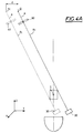
- this apparatus also comprises means 40 for determining the position of the target C from at least one and preferably two images obtained from two different angular positions S 1 , S 2 of the source 22
- the apparatus therefore also includes means (not shown) for moving the source 22, which are well known to those skilled in the art.
- the receiving device 30 is produced in the form of a bar 32, means of displacement 34 of said bar 32 being provided for moving said bar 32 so as to cover at least the entire area of the target C.
- the aforementioned source 22 is a source of X-ray radiation and the reception device 30 comprises discrete elements, referenced e 1 , e 2 ..., e n in FIG. 2, which are sensitive to X-radiation, preferably arranged parallel and aligned to define a linear active receiving surface.
- the source 22 is a source of X-ray radiation and the reception device 30 comprises at least one fluorescent screen sensitive to X-rays and discrete elements, referenced e 1 , e 2. ., e n , Figure 2, sensitive to fluorescent radiation from this screen, for example discrete elements sensitive to light photons.
- the discrete elements e 1 to e n comprise components in the solid state and sensitive to X-radiation, for example with semiconductor elements.
- means of movement 34 of the reception device 30 are provided, capable of carrying out a movement of the reception device 30 according to a predetermined known speed of movement, as well as calculation means 40 , comprising for example a computer, computer or microcomputer, making it possible to calculate the position of the reception device 30 at a given time from of the known travel time and travel speed, as can be seen from the consideration of FIG. 5 which shows the movement of movement of the bar 32 as a function of time during the movement.
- the positions of the bar 32 are shown t 0 , t 1 , t 2 up to t 8 for example.
- means for determining the position of the reception device 30 at a given time are provided to determine which is the discrete element among the elements e 1 to e n , which has received the image of the target C, and at what time t, for each of the two images resulting from two different angular positions S 1 , S 2 , represented in FIG. 48 of the radiation source 22, as well as for determining the exact position in space of target C from knowledge of the exact position of the two discrete elements having received the two images of target C resulting from the two positions S 1 , S 2 of the radiation source 22.
- These determination means are preferably integrated into the abovementioned calculation means 40.
- a control screen 50 is provided on which at least one image of the target C obtained during the movement of the reception device 30 is projected, as well as means 52 such as a keyboard or a mouse , well known to those skilled in the art, making it possible to point the position of the target C on the screen 50 and calculating means 40 making it possible to calculate the position of the target C with the pointing means 52 for each image.
- a collimation device 60 is provided, making it possible to limit the area of radiation in space, thereby limiting the irradiation of the patient.
- means, symbolized here 70, 72 are provided for simultaneously moving the radiation source 22, the collimation device 60 and the receiving device 30, in order to greatly limit the volume and the time of irradiation.
- These displacement means advantageously carry out either a translational displacement, or a rotation in a direction not perpendicular to the line defined by the linear active part formed by the sensitive elements e 1 to e n .
- means 70, 72 will be provided for moving the reception device 30 and in synchronism the collimation device 60, so that the radiation substantially covers only said receiving device, which greatly limits the volume and the irradiation time.
- the apparatus as a whole which has just been described may constitute an apparatus for treating a target C, preferably here by pressure waves.
- This target is in particular chosen from the group consisting of a lithiasis, for example a renal or biliary lithiasis; tissue, for example benign or malignant tumors; bone, for example a fracture or an osteoporosis area.
- the radiation (R) of the source here in position S 1
- R 1 the radiation of the source, here in position S 1
- R 1 the dimension of the receiving device 30, that is to say to the dimension of the strip 32 to cover the set of discrete elements e 1 to e n .
- the distance of the displacement d between the position in phantom line and the position in strong line of the processing device, in the direction Y, is clearly visible in FIG. 4A. It is observed that the source 22 has passed from the position S 1 to the position S ′ 1 by having passed opposite the target C.
- the position of the source 22 can be modified to place it in the position S 2 , with a different inclination relative to the receiving device and the target C.
- This position S 2 is for example an inclination of about 20 ° on the other side of the vertical ZZ passing through the target C.
- the calculation means 40 then make it possible to calculate the exact position of the target C in a simple manner.
- the practitioner can participate in this procedure by pointing himself with the pointing means 52 the image of the target C on the screen means 50, which also allows the calculation means 40 to quickly perform the exact calculation of the position of the target C in space relative to an initial reference position of the processing device 12.
- This initial position, or reference point 0, can for example be the initial position of the external focal point F 2 or focal point of the waves pressure of the treatment device 12.
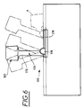
- FIG. 6 there is shown a second embodiment of a processing device according to the invention represented by the general reference number 100.
- the pressure wave generator is referenced 112
- the emission device is referenced 120
- the reception device is referenced 130.
- the source itself is referenced 122.
- the reception device 130 has its active part also linear and subdivided into a multiplicity of discrete elements aligned e 1 to e n identical to those of the previous embodiment, and the first e 1 and the last e n of which have been identified in FIG. 9.
- the reception device 130 has the form of a bar 132 with a linear active part.
- the means of displacement of the bar 132 are here referenced 170 thus corresponding to the means 70 of simultaneous displacement provided in the embodiment of Figures 1 to 5.
- the displacement means 170 allow according to a currently preferred embodiment, as shown , a displacement in translation, preferably in a direction substantially perpendicular to the sensitive active part of the receiving device 132.
- the displacement means make it possible to achieve a displacement in rotation in a direction not perpendicular to the line defined by said linear active part 132.
- These means of simultaneous movement 170 of the emission device 120 and of the reception device 130 here comprising a C-shaped arm marked 172 whose first end 172a supports the emission device 120 comprising the radiation source 122 and the radiation device.
- collimation 160 and a second end 172b supports the radiation reception device 130 integrating here the strip 132 of the sensitive elements e 1 to e n .
- These displacement means 170 thus constitute a common support for the radiation source 122, the collimation device 160 and the reception device 130.
- these displacement means 170 forming a common support are mounted in rotation about an axis of rotation 174 arranged substantially perpendicular to the longitudinal axis of the device 100 as is clearly visible in Figures 6 to 8
- This longitudinal axis usually also corresponds to the longitudinal axis of a table 190 on which the patient to be treated lies down.
- This table 190 is preferably removable, in particular to allow complete tilting of the displacement means 170 in the rest position R shown in FIG. 7 allowing a minimum volume to be occupied during storage and transport.
- the displacement means 170 forming a common support device are mounted on a translation device 176 mounted in sliding by translation on guide rails 178, mounted parallel to the longitudinal axis of the device. It is understood that the displacement means 170 forming a common support device, here in the form of an arm 172 at C are arranged laterally with respect to the work table 190 intended to receive the patient and so that the ends 172a, 172b respectively supporting the device 120 and the receiving device 130 are arranged on either side of the work table 190, therefore on either side of the patient and of the target area C.
- the structure of the displacement means 170 is an integral part of the invention and is independently patentable.
- the invention also provides independently patentable the design of the emission device 120 by providing that the emission source 122 includes a generator element 180 emitting radiation 182 whose initial direction is substantially perpendicular to the plane P reception defined by the substantially linear active surface of the strip 132 formed by the elements e 1 to e n for receiving radiation.
- the initially perpendicular radiation 182 is returned in the direction of the plane P by a return or retransmission device such as a cathode 184 having an inclined face 186 ensuring this return or this retransmission of the radiation 182.
- the preferred radiation source is according to the invention an X-ray source comprising an X-ray tube whose axis is advantageously disposed substantially perpendicular to the direction of the receiving plane P, and at least part of which is re-emitted by the deflection device formed here by a cathode 184
- the collimating device 160 has a collimating slit 162 arranged parallel to the plane P, and therefore also perpendicular to the initial direction of the radiation 182, and the dimension of which is designed to provide radiation of which the dimension is substantially close to, or slightly greater , to the dimension of the substantially linear active part forming a bar 132 of the device reception f 130.
- the variations in intensity of the radiation reaching the active part of the bar 132 are minimized, so that their effect becomes negligible on the quality of the image finally obtained, due to the substantially linear dimension of the bar.
- This bar 132 can, for example, have about 0.6 mm wide by 230.4 mm long. Therefore, the collimation device 160 will produce a very fine, substantially flat beam passing through the patient in the direction of the bar, which will minimize the amount of radiation received by the patient, which is particularly important in the preferred case of employment.
- the dimension of the slot 162 of the collimation device 160 so that the width of the planar beam P at the level of the bar 132 is substantially equal to or slightly greater than that of the surface acquired from the strip 132, all of the radiation passing through the patient is useful for imaging.
- the displacement means 172 forming a common support device for the emission source 120 and the reception device 130 and possibly the collimation device 160, a mechanical and non-deformable connection of these devices is produced, which guarantees, by a single initial adjustment, that the radiation always arrives on the active part of the bar 132 of the reception device 130 whatever the displacement or the orientation of the assembly.
- the intensity of the received radiation will be constant, so there is no risk of variation of intensity of the radiation from one line to another during the scanning of the area to be imaged.
- the displacement means 170 are translated by means of translation means 176 along the patient opposite the area to be imaged.
- at least two images are produced with two different inclinations of the displacement means 170, providing two different angular orientations of the radiation source 120.
- the first orientation can, by example, be vertical as shown in Figures 6 to 8 and the second position can be tilted left or right from the vertical position as shown in Figure 6, with a translated position shown in phantom, so as to form two images.
- the axis of rotation 174 is arranged halfway up the area to be imaged.
- the displacement means forming a common support device 170 here in the form of an arm C 172 can be manufactured with precision, the mounting of any preset strip 132 and of any preset radiation source 122 ensure good alignment of the beam on the linear active area of the bar 132. Therefore, it is possible to provide, inside the ends 172a, 172b of the arm, precise mechanisms for adjusting the position of the source respectively, for example by adjusting the position of the return device 184 or the bar 132 integrated at the end 172b. It is also possible to preset the position of the collimation device 160, this device also being integrated in the end 172a of the arm 172.
- the positions are rigidly locked.
- this can be mounted on a frame allowing movement in X and Y and a blocking in the desired position on the end 172b of the arm 172.
- Figures 1 to 9 are an integral part of the present invention and are therefore an integral part of this description.
- the invention also covers any characteristic which will appear new vis-à-vis any prior art resulting from the previous description incorporating Figures 1 to 9.
Landscapes
- Health & Medical Sciences (AREA)
- Life Sciences & Earth Sciences (AREA)
- Engineering & Computer Science (AREA)
- Physics & Mathematics (AREA)
- Medical Informatics (AREA)
- Heart & Thoracic Surgery (AREA)
- Surgery (AREA)
- Nuclear Medicine, Radiotherapy & Molecular Imaging (AREA)
- Optics & Photonics (AREA)
- Pathology (AREA)
- Radiology & Medical Imaging (AREA)
- Biomedical Technology (AREA)
- Biophysics (AREA)
- Molecular Biology (AREA)
- High Energy & Nuclear Physics (AREA)
- Animal Behavior & Ethology (AREA)
- General Health & Medical Sciences (AREA)
- Public Health (AREA)
- Veterinary Medicine (AREA)
- Electromagnetism (AREA)
- General Physics & Mathematics (AREA)
- Radar, Positioning & Navigation (AREA)
- Remote Sensing (AREA)
- Radiation-Therapy Devices (AREA)
- Apparatus For Radiation Diagnosis (AREA)
Abstract
Description
La présente invention concerne essentiellement un procédé et un appareil de détermination de la position exacte d'une cible par rapport à un repère de référence de coordonnées connues à l'aide d'un dispositif de réception comprenant une partie active linéaire formée d'une multiplicité d'éléments discrets sensibles aux rayonnements.The present invention essentially relates to a method and an apparatus for determining the exact position of a target relative to a reference frame of known coordinates using a reception device comprising a linear active part formed by a multiplicity discrete elements sensitive to radiation.
L'invention concerne plus particulièrement aussi l'utilisation de ce procédé et de cet appareil de détermination de la position exacte d'une cible dans le cadre d'un appareil de traitement d'une cible, de préférence par ondes de pression. Selon un mode de réalisation préféré, il s'agit d'un appareil de traitement par ondes de pression d'une cible choisie parmi le groupe consistant d'une lithiase, par exemple une lithiase rénale ou biliaire ; de tissus, par exemple des tumeurs bénignes ou malignes ; des os, par exemple une fracture ou une zone osseuse à traiter, notamment une zone d'ostéoporose.The invention relates more particularly also to the use of this method and of this apparatus for determining the exact position of a target within the framework of an apparatus for treating a target, preferably by pressure waves. According to a preferred embodiment, it is an apparatus for pressure wave treatment of a target chosen from the group consisting of a lithiasis, for example a renal or biliary lithiasis; tissue, for example benign or malignant tumors; bones, for example a fracture or a bone area to be treated, in particular an osteoporosis area.
On connaît jusqu'à présent divers procédés et appareils pour déterminer la position exacte d'une cible, comprenant l'emploi d'une source de rayonnement émettant un rayonnement capable d'être reçu par un dispositif de réception de ce rayonnement, ladite source et ledit dispositif de réception étant disposés de part et d'autre de ladite cible (voir EP-A-O 240 565 ou EP-A-O 260 550).Until now, various methods and apparatuses are known for determining the exact position of a target, comprising the use of a radiation source emitting radiation capable of being received by a device for receiving this radiation, said source and said receiving device being arranged on either side of said target (see EP-AO 240,565 or EP-AO 260,550).
Le document Siemens DE-U-87 13524 = US-A-4 914 588 décrit un appareil de formation d'image par tomographie nécessitant pour construire l'image une mise en rotation autour d'un axe de rotation parallèle au corps du patient pour tourner autour de celui-ci. Le patient est en général déplacé avec la table de support et ce dispositif nécessite un système ultrasonique de localisation complémentaire.The document Siemens DE-U-87 13524 = US-A-4 914 588 describes an image forming apparatus by tomography requiring to construct the image a rotation around an axis of rotation parallel to the patient's body to revolve around it. The patient is generally moved with the support table and this device requires an additional ultrasonic localization system.
De même, le document EP-A-318 106 Philips = US-A-4 967 735 décrit un appareil de destruction de concrétion comprenant un ensemble fluoroscopique combiné à un ensemble de détection de photons diffusés, avec emploi d'un diaphragme comportant une position de pleine ouverture et une position d'ouverture réduite. La position notamment de la source de rayonnement apparaît être fixe ce qui conduit généralement à une irradiation importante du patient.Likewise, document EP-A-318 106 Philips = US-A-4 967 735 describes an apparatus for destroying concretion comprising a fluoroscopic assembly combined with a scattered photon detection assembly, using a diaphragm having a full opening position and a reduced opening position. The position in particular of the radiation source appears to be fixed, which generally leads to significant irradiation of the patient.
On connaît par ailleurs, par le document US-A-4 764 944 (Finlayson) un procédé et un dispositif pour positionner un calcul se trouvant à l'intérieur d'un rein d'un patient utilisant deux sources de rayonnement pénétrant convergent se croisant au point focal F2 constituant le foyer externe d'une ellipsoïde où sont générées des ondes de choc. Ici la position initiale des sources n'est pas quelconque, mais au contraire doit être bien précise pour se croiser au point focal. En outre, la solution technique proposée par Finlayson nécessite une étape de calibrage pour déterminer la valeur de l'angle a entre les coordonnées dans le plan d'observation et déterminer l'angle entre le plan d'observation et l'horizontale. On utilise en particulier une tige se terminant par une bille que l'on observe jusqu'à ce que la radiation observée par les fluoroscopes soit centrée sur le point d'intersection de chacun des écrans. Cette procédure est donc extrêmement compliquée et exige dans tous les cas l'utilisation de deux sources et de deux dispositifs de réception, en particulier des fluoroscopes dont la position initiale doit être bien déterminée pour chacun d'eux par son second foyer, ce qui exige que ces sources soient liées en permanence au dispositif de traitement, ici une ellipsoïde. En outre, un calibrage est nécessaire à l'aide du dispositif comportant la bille pour amener l'image de la bille au centre des écrans des fluoroscopes.We also know from document US-A-4 764 944 (Finlayson) a method and a device for positioning a calculus located inside a kidney of a patient using two sources of convergent penetrating radiation crossing each other at the focal point F2 constituting the external focus of an ellipsoid where shock waves are generated. Here the initial position of the sources is not arbitrary, but on the contrary must be very precise to cross at the focal point. In addition, the technical solution proposed by Finlayson requires a calibration step to determine the value of the angle a between the coordinates in the observation plane and to determine the angle between the observation plane and the horizontal. In particular, a rod ending in a ball is used which is observed until the radiation observed by the fluoroscopes is centered on the point of intersection of each of the screens. This procedure is therefore extremely complicated and in all cases requires the use of two sources and two reception devices, in particular fluoroscopes, the initial position of which must be well determined for each of them by its second focal point, which requires that these sources are permanently linked to the processing device, here an ellipsoid. In addition, calibration is necessary using the device comprising the ball to bring the image of the ball to the center of the fluoroscope screens.
Par ailleurs, le déposant a également décrit dans le document WO-A-91/07913 un procédé et un appareil de détermination de la position d'une cible utilisant un dispositif de masquage combiné à un film sensible aux rayons X. Cette solution qui est sûre et fiable exige cependant un temps de développement minimum du film qui n'est pas toujours compatible avec les exigences industrielles et médicales.Furthermore, the applicant has also described in document WO-A-91/07913 a method and an apparatus for determining the position of a target using a masking device combined with an X-ray sensitive film. This solution which is Safe and reliable, however, requires a minimum film development time which is not always compatible with industrial and medical requirements.
La présente invention a donc pour but principal de résoudre le nouveau problème technique consistant en la fourniture d'une solution permettant de déterminer la position exacte d'une cible en un temps relativement court tout en étant d'une grande fiabilité et reproductibilité.The main object of the present invention is therefore to solve the new technical problem consisting in providing a solution making it possible to determine the exact position of a target in a relatively short time while being very reliable and reproducible.
La présente invention a encore pour but principal de résoudre le nouveau problème technique consistant en la fourniture d'une solution permettant de déterminer la position exacte d'une cible sans avoir à réaliser un déplacement quelconque du dispositif de traitement du patient et/ou du patient.The main object of the present invention is also to solve the new technical problem consisting in providing a solution making it possible to determine the exact position of a target without having to carry out any movement of the patient and / or patient treatment device. .
La présente invention a encore pour but principal de résoudre le nouveau problème technique consistant en la fourniture d'un procédé et d'un appareil pour déterminer la position exacte d'une cible sans avoir à amener cette cible dans une position déterminée relativement au dispositif de traitement et/ou sans avoir à l'amener dans une position déterminée relativement au dispositif de réception du rayonnement.The main object of the present invention is also to solve the new technical problem consisting in providing a method and an apparatus for determining the exact position of a target without having to bring this target into a determined position relative to the detection device. treatment and / or without having to bring it into a determined position relative to the radiation receiving device.
La présente invention a encore pour but principal de résoudre le nouveau problème technique consistant en la fourniture d'un procédé et d'un appareil pour déterminer la position exacte d'une cible utilisant un rayonnement d'intensité sensiblement uniforme lors de sa réception par le dispositif de réception, afin d'améliorer la qualité de l'image obtenue.The main object of the present invention is also to solve the new technical problem consisting in providing a method and an apparatus for determining the exact position of a target using radiation of substantially uniform intensity when it is received by the receiving device, in order to improve the quality of the image obtained.
La présente invention a encore pour but de résoudre le nouveau problème technique consistant en la fourniture d'un procédé et d'un appareil plus simples, d'un réglage et d'une maintenance faciles, réduisant l'exposition du patient aux rayonnements, ce qui est particulièrement important dans le cas de rayonnements X et permettant d'occuper un empâtement minimum au stockage et au transport.Another object of the present invention is to solve the new technical problem consisting in providing a simpler method and apparatus, easy adjustment and maintenance, reducing the patient's exposure to radiation, this which is particularly important in the case of X-rays and enabling a minimum impasto to be occupied during storage and transport.
La présente invention a encore pour but de résoudre les problèmes techniques énoncés ci-dessus, avec un minimum de manipulations, notamment un minimum d'étapes, ou de prises de vue ou de déplacements, en limitant ainsi également la dose d'exposition au rayonnement émis par la source de rayonnement, ce qui est particulièrement important lorsque la source de rayonnement émet des rayons X.Another object of the present invention is to solve the technical problems stated above, with a minimum of manipulation, in particular a minimum of steps, or of shots or of displacements, thereby also limiting the dose of exposure to radiation. emitted by the radiation source, which is particularly important when the radiation source emits X-rays.
La présente invention a encore pour but de résoudre les nouveaux problèmes techniques énoncés ci-dessus d'une manière telle que la solution retenue permette d'utiliser le procédé et l'appareil de l'invention dans le cadre d'un appareil de traitement de cible, de préférence par ondes de pression, encore de préférence cette cible étant choisie parmi le groupe consistant d'une lithiase, par exemple rénale ou biliaire ; ce tissus, par exemple de tumeurs bénignes ou malignes ; et d'os, par exemple une zone osseuse, telle qu'une fracture ou une zone d'ostéoporose.Another object of the present invention is to solve the new technical problems stated above in such a way that the solution adopted makes it possible to use the method and the apparatus of the invention in the context of a treatment apparatus for target, preferably by pressure waves, more preferably this target being chosen from the group consisting of a lithiasis, for example renal or biliary; this tissue, for example benign or malignant tumors; and bone, for example a bone area, such as a fracture or an osteoporosis area.
La présente invention permet de résoudre pour la première fois ces problèmes techniques de manière simultanée, particulièrement simple, peu coûteuse et utilisable à l'échelle industrielle et médicale.The present invention makes it possible for the first time to solve these technical problems simultaneously, particularly simple, inexpensive and usable on an industrial and medical scale.
Ainsi, selon un premier aspect, la présente invention fournit un procédé pour déterminer la position exacte d'une cible (C) par rapport à un point de référence (0) déterminé par exemple par un dispositif de traitement de la cible (C), comprenant l'emploi d'un dispositif d'émission comorenant une source oe rayonnement émettant un rayonnement de formation d'image au moins de la cible (C) capable d'être reçu par un dispositif de réception de ce rayonnement, ladite source et ledit dispositif de réception étant disposés de part et d'autre de ladite cible (C), ladite source étant de position connue par rapport au point de référence (0), et en ce ou'on détermine la position de la cible (C) à partir d'au moins une image de ladite cible (C), caractérisé en ce qu'on prévoit le dispositif de réception sous forme d'une barrette comprenant une partie active linéaire formée d'une multiplicité d'éléments discrets (e1 - en) sensibles au rayonnement dont les positions dans l'espace sont connues, et en ce qu'on réalise au moins un déplacement de la source de rayonnements et le dispositif de réception simultanément, sur une distance connue permettant d'émettre un rayonnement couvrant au moins la zone de la cible selon un déplacement choisi parmi une rotation autour d'un axe non perpendiculaire à la ligne définie par ladite partie active linéaire, et une translation, en obtenant ainsi au moins une image de la cible (C), et en ce qu'on détermine la position de la cible (C) à partir de ladite image et de ladite distance de déplacement connue.Thus, according to a first aspect, the present invention provides a method for determining the exact position of a target (C) relative to a reference point (0) determined for example by a device for processing the target (C), comprising the use of an emission device comprising a source of radiation emitting imaging radiation at least from the target (C) capable of being received by a device for receiving this radiation, said source and said receiving device being arranged on either side of said target (C), said source being of known position relative to the reference point (0), and in that the position of the target (C) is determined from at least one image of said target (C), characterized in that the receiving device is provided in the form of a bar comprising a linear active part formed by a multiplicity of discrete elements (e 1 - e n ) sensitive to radiation whose positions in space are known, and in that at least one displacement of the radiation source and the reception device is carried out simultaneously, over a known distance making it possible to emit radiation covering at least the target area according to a displacement chosen from a rotation around an axis not perpendicular to the line defined by said linear active part, and a translation, thereby obtaining at least one image of the target (C), and in that the position of the target (C) from said image and said known displacement distance.
Selon un mode de réalisation avantageux, on réalise le déplacement précité en translation pour au moins deux orientations ou inclinaisons différentes de la source de rayonnement et du dispositif de réception associé.According to an advantageous embodiment, the above-mentioned movement in translation is carried out for at least two different orientations or inclinations of the radiation source and of the associated reception device.
Selon un autre mode de réalisation avantageux, on déplace simultanément la source de rayonnement et le dispositif de réception en rotation selon un axe de rotation sensiblement parallèle à la ligne définie par la partie active linéaire précitée.According to another advantageous embodiment, the radiation source and the receiving device are rotated simultaneously along an axis of rotation substantially parallel to the line defined by the above-mentioned linear active part.
Selon un autre mode de réalisation de l'invention, la source de rayonnement et le dispositif de réception sont montés sur un dispositif support commun unique, de préférence en forme de bras en C dont une extrémité est disposée au-dessus de la cible et dont l'autre extrémité est disposée en dessous de la cible. Avantageusement, le disoositif support commun est monté en rotation autour d'un axe de rotation avantageusement disposé sensiblement perpendiculairement à l'axe longitudinal de l'aopareil qui est habituellement défini par l'axe longitudinal d'une table dite de travail, de support d'un patient allongé sur ladite table selon le même axe longitudinal ; cet axe de rotation étant de préférence monté parallèle à la surface active sensible du dispositif de réception.According to another embodiment of the invention, the radiation source and the reception device are mounted on a single common support device, preferably in the form of a C-arm, one end of which is disposed above the target and of which the other end is arranged below the target. Advantageously, the common support device is mounted for rotation about an axis of rotation advantageously disposed substantially perpendicular to the longitudinal axis of the apparatus which is usually defined by the longitudinal axis of a so-called work table, of support d 'a patient lying on said table along the same longitudinal axis; this axis of rotation being preferably mounted parallel to the sensitive active surface of the receiving device.
Selon une variante de réalisation particulière, on déplace en translation le dispositif support commun dans une direction sensiblement perpendiculaire à l'axe de rotation qui est lui-même monté parallèle à la surface active sensible du dispositif de réception.According to a particular variant embodiment, the common support device is moved in translation in a direction substantially perpendicular to the axis of rotation which is itself mounted parallel to the sensitive active surface of the receiving device.
Selon une autre variante de réalisation particulière, on déplace en translation le dispositif support commun sur une distance permettant d'émettre un rayonnement couvrant au moins la zone de la cible ; ce déplacement en translation étant réalisé pour au moins deux orientations ou inclinaisons différentes du dispositif support commun obtenues par une simple mise en rotation autour de l'axe de rotation.According to another particular variant embodiment, the common support device is moved in translation over a distance making it possible to emit radiation covering at least the area of the target; this translational movement being carried out for at least two different orientations or inclinations of the common support device obtained by a simple rotation around the axis of rotation.
Selon un mode de réalisation particulier, le dispositif support commun est monté en rotation sur un élément support faisant partie d'un chariot monté déplaçable en translation sur au moins un, ou de préférence deux rails de guidage en translation solidaires du châssis de l'appareil.According to a particular embodiment, the common support device is mounted in rotation on a support element forming part of a carriage mounted movable in translation on at least one, or preferably two guide rails in translation secured to the chassis of the device. .
Selon un autre mode de réalisation, la source est une source de rayonnement X et le dispositif de réception précité comprend des éléments discrets sensibles au rayonnement X.According to another embodiment, the source is a source of X-radiation and the aforementioned reception device comprises discrete elements sensitive to X-radiation.
Selon encore un autre mode de réalisation de l'invention, la source précitée est une source de rayonnement X et le dispositif de rayonnement précité comprend au moins un écran fluorescent sensible aux rayons X et des éléments discrets sensibles au rayonnement fluorescent de cet écran, par exemple des éléments discrets sensibles aux photons lumineux.According to yet another embodiment of the invention, the aforementioned source is an X-ray source and the aforementioned radiation device comprises at least one fluorescent screen sensitive to X-rays and discrete elements sensitive to the fluorescent radiation of this screen, by example of discrete elements sensitive to light photons.
Selon un autre mode de réalisation, les éléments discrets comprennent des composants à l'état solide et sensibles au rayonnement X, par exemple à éléments semi-conducteurs.According to another embodiment, the discrete elements comprise components in the solid state and sensitive to X-radiation, for example with semiconductor elements.
Selon un autre mode de réalisation, le procédé réalise le déplacement du dispositif de réception selon une vitesse de déplacement connue prédéterminée, ce qui permet de déterminer la position du dispositif de réception à un moment donné.According to another embodiment, the method carries out the movement of the reception device according to a predetermined known speed of movement, which makes it possible to determine the position of the reception device at a given time.
Selon un autre mode de réalisation, le procédé détermine quel est l'élément discret qui a reçu l'image de la cible (C), pour chacune des deux images résultant de deux positions angulaires différentes de la source de rayonnement, et à partir de la connaissance de la position exacte des deux éléments discrets ayant reçu les deux images de la cible C résultant des deux positions de la source de rayonnement, on détermine la position exacte dans l'espace de la cible.According to another embodiment, the method determines which discrete element has received the image of the target (C), for each of the two images resulting from two different angular positions of the radiation source, and from knowing the exact position of the two discrete elements having received the two images of the target C resulting from the two positions of the radiation source, the exact position in the space of the target is determined.
Selon un autre mode de réalisation, le procédé prévoit un écran de contrôle sur lequel on projette au moins une image de la zone de la cible C obtenue lors du déplacement du dispositif de réception précité, ainsi que des moyens de pointage de la position de la cible C sur l'écran et des moyens de calcul permettant de calculer la position de la cible C avec les moyens de pointage, pour chaque image.According to another embodiment, the method provides a control screen on which at least one image of the area of the target C obtained during the movement of the aforementioned reception device is projected, as well as means for pointing the position of the target C on the screen and calculation means making it possible to calculate the position of target C with the pointing means, for each image.
Selon un autre mode de réalisation, le procédé prévoit un dispositif de collimation permettant de limiter dans l'espace la zone de rayonnement, ce qui permet de limiter l'irradiation du patient ; de préférence déplacé simultanément avec la source de rayonnement et le dispositif de réception précités.According to another embodiment, the method provides a collimation device making it possible to limit in space the radiation area, which makes it possible to limit the irradiation of the patient; preferably moved simultaneously with the aforementioned radiation source and receiving device.
Selon encore un autre mode de réalisation, le procédé prévoit que le dispositif de réception comprend ladite partie active linéaire formée par une multiplicité d'éléments discrets alignés sensibles au rayonnement dont les positions dans l'espace sont connues, définissant un plan général de réception du rayonnement, on prévoit que la source d'émission du rayonnement émette ce rayonnement initialement dans une direction sensiblement perpendiculaire au plan de réception, ce rayonnement initialement perpendiculaire à ce plan étant renvoyé par un dispositif de renvoi pouvant éventuellement réémettre ce rayonnement, dans une direction parallèle au plan de réception, et on prévoit un dispositif de collimation comprenant une fente de collimation parallèle au plan de réception et limitant la zone de rayonnement sensiblement à la dimension sensiblement linéaire de la partie active du dispositif de réception. De préférence, la source d'émission du rayonnement est un tube à rayons X dont l'axe est avantageusement disposé sensiblement perpendiculairement à la direction du plan de réception. Grâce à l'invention, on minimise les variations d'intensité du rayonnement atteignant la zone sensible du dispositif de réception grâce au fait qu'il a été observé que le rayonnement est davantage uniforme lorsque la source a son axe disposé sensiblement perpendiculairement à la direction du plan de réception, après avoir été renvoyé dans ce plan par un dispositif de renvoi généralement dénommé cathode.According to yet another embodiment, the method provides that the receiving device comprises said linear active part formed by a multiplicity of aligned discrete elements sensitive to radiation whose positions in space are known, defining a general plane for receiving the radiation, it is expected that the emission source of the radiation emits this radiation initially in a direction substantially perpendicular to the receiving plane, this radiation initially perpendicular to this plane being returned by a deflection device which can optionally re-emit this radiation, in a parallel direction at the reception plane, and a collimation device is provided comprising a collimation slot parallel to the reception plane and limiting the radiation area substantially to the substantially linear dimension of the active part of the reception device. Preferably, the source of emission of the radiation is an X-ray tube, the axis of which is advantageously disposed substantially perpendicular to the direction of the receiving plane. Thanks to the invention, variations in the intensity of the radiation reaching the sensitive zone of the reception device are minimized thanks to the fact that it has been observed that the radiation is more uniform when the source has its axis disposed substantially perpendicular to the direction. of the reception plan, after having been returned to this plan by a return device generally called a cathode.
Grâce au fait que la source d'émission et le dispositif de réception sont liés mécaniquement en étant montés sur un dispositif support commun, on simplifie la conception de la structure de l'appareil et la mise en oeuvre du procédé de repérage, le réglage et la maintenance sont faciles. L'exposition du patient aux rayonnements est réduite, ce qui particulièrement intéressant dans le cas des rayons X. En outre, par le montage du dispositif support commun en rotation et également en translation, il est possible de dégager complètement le support commun pour l'allonger le long de l'appareil ce qui limite l'encombrement lors du stockage ou du transport, sans démontage. On peut aussi prérégler la fabrication du dispositif émetteur de rayonnement ainsi que le dispositif de réception.Thanks to the fact that the emission source and the reception device are mechanically linked by being mounted on a common support device, the design of the structure of the apparatus is simplified and the implementation of the tracking method, the adjustment and maintenance is easy. The patient's exposure to radiation is reduced, which is particularly advantageous in the case of X-rays. In addition, by mounting the support device common in rotation and also in translation, it is possible to completely disengage the common support to lengthen it along the device which limits the size during storage or transport, without dismantling. It is also possible to preset the manufacture of the radiation emitting device as well as the receiving device.
Selon un deuxième aspect, la présente invention fournit un appareil pour déterminer la position exacte d'une cible (C) par rapport à un point de référence (0) déterminé par exemple par un dispositif de traitement de la cible C, comprenant un dispositif d'émission comprenant une source de rayonnement émettant un rayonnement de formation d'image au moins de la cible C capable d'être reçu par un dispositif de réception de ce rayonnement, ladite source et ledit dispositif de réception étant disposés de part et d'autre de ladite cible C, ladite source étant de position connue par rapport au point de référence (0) ; et par des moyens de détermination de la position de la cible C à partir d'au moins une image de ladite cible, caractérisé en ce que le dispositif de réception est réalisé sous forme d'une barrette comprenant une surface active linéaire formée d'une multiplicité d'éléments discrets (e1 à en) alignés sensibles au rayonnement dont les positions dans l'espace sont connues ; et des moyens de déplacement pour déplacer simultanément la source de rayonnement et le dispositif de réception, sur une distance de déplacement connue permettant d'émettre un rayonnement couvrant au moins la zone de la cible C pour obtenir au moins une image de ladite cible C; lesdits moyens de déplacement étant prévus pqur réaliscr un déplacement choisi parmi un déplacement en rotation autour d'un axe non-perpendiculaire à la ligne définie par ladite partie active linéaire et une translation ; lesdits moyens de détermination de la position de la cible C comprenant des moyens de calcul de la position de la cible C à partir de ladite image de la cible C et de la distance de déplacement connue.According to a second aspect, the present invention provides an apparatus for determining the exact position of a target (C) relative to a reference point (0) determined for example by a device for processing the target C, comprising a device for emission comprising a radiation source emitting imaging radiation at least from the target C capable of being received by a device for receiving this radiation, said source and said receiving device being arranged on either side of said target C, said source being of known position relative to the reference point (0); and by means for determining the position of the target C from at least one image of said target, characterized in that the reception device is produced in the form of a bar comprising a linear active surface formed by a multiplicity of discrete elements (e 1 to e n ) aligned sensitive to radiation whose positions in space are known; and displacement means for simultaneously displacing the radiation source and the reception device, over a known displacement distance making it possible to emit radiation covering at least the area of the target C to obtain at least one image of said target C; said displacement means being provided for carrying out a displacement chosen from a rotational displacement around an axis not perpendicular to the line defined by said linear active part and a translation; said means for determining the position of target C comprising means for calculating the position of target C from said image of target C and the known displacement distance.
Selon un mode de réalisation indépendamment brevetable, la source de rayonnement et le dispositif de réception sont montés sur un dispositif support commun, de préférence ayant une forme de bras en C dont les extrémités sont disposées de part et d'autre de la cible.According to an independently patentable embodiment, the radiation source and the reception device are mounted on a common support device, preferably having the shape of a C-arm, the ends of which are arranged on either side of the target.
Selon un mode de réalisation particulier, le dispositif d'émission précité comprend des moyens de déplacement de la source de rayonnement entre deux positions angulaires différentes et des moyens de détermination de la position de la cible (C) à partir d'au moins deux images obtenues à partir de deux positions angulaires différentes de la source.According to a particular embodiment, the above-mentioned emission device comprises means for moving the radiation source between two different angular positions and means for determining the position of the target (C) from at least two images obtained from two different angular positions of the source.
Selon encore un autre mode de réalisation, la source précitée est une source de rayonnement X et le dispositif de réception précité comprend des éléments discrets et sensibles au rayonnement X.According to yet another embodiment, the aforementioned source is a source of X-ray radiation and the aforementioned reception device comprises discrete elements and sensitive to X-radiation.
Selon encore une autre variante de réalisation de l'invention, la source est une source de rayonnement X et le dispositif de réception précité comprend au moins un écran fluorescent sensible aux rayons X et des éléments discrets sensibles au rayonnement fluorescent de cet écran, par exemple des éléments discrets et sensibles aux photons lumineux.According to yet another alternative embodiment of the invention, the source is a source of X-ray radiation and the aforementioned reception device comprises at least one fluorescent screen sensitive to X-rays and discrete elements sensitive to the fluorescent radiation of this screen, for example discrete elements sensitive to light photons.
Selon encore un autre mode de réalisation, les éléments discrets comprennent des composants à l'état solide et sensibles au rayonnement X, par exemple à éléments semi-conducteurs.According to yet another embodiment, the discrete elements comprise components in the solid state and sensitive to X-radiation, for example with semiconductor elements.
Selon encore un autre mode de réalisation, des moyens de détermination de la position du dispositif de réception à un moment donné sont prévus pour déterminer quelle est la position exacte de l'élément discret qui a reçu l'image de la cible (C), et l'instant où cet élément a reçu l'image, pour chacune de deux images résultant de deux positions angulaires différentes de la source de rayonnement, ainsi que pour déterminer la position exacte dans l'espace de la cible (C) à partir de cette connaissance de la position exacte des deux éléments discrets ayant reçu les deux images de la cible C résultant des deux positions de la source de rayonnement.According to yet another embodiment, means for determining the position of the reception device at a given time are provided for determining what is the exact position of the discrete element which has received the image of the target (C), and the instant when this element received the image, for each of two images resulting from two different angular positions of the radiation source, as well as to determine the exact position in space of the target (C) from this knowledge of the exact position of the two discrete elements having received the two images of the target C resulting from the two positions of the radiation source.
Selon une variante de réalisation particulière, un écran de contrôle est prévu sur lequel au moins une image de la zone de la cible C obtenue lors du déplacement du dispositif de réception précité est projetée, ainsi que des moyens de pointage de la position de la cible C sur l'écran et des moyens de calcul permettant de calculer la position de la cible C avec les moyens de pointage, pour chaque image.According to a particular embodiment, a control screen is provided on which at least one image of the area of the target C obtained during the movement of the aforementioned reception device is projected, as well as means for pointing the position of the target C on the screen and calculation means making it possible to calculate the position of the target C with the pointing means, for each image.
Selon encore un autre mode de réalisation, un dispositif de collimation est prévu, permettant de limiter dans l'espace la zone de rayonnement, en limitant ainsi l'irradiation du patient.According to yet another embodiment, a collimation device is provided, making it possible to limit the area of radiation in space, thereby limiting the irradiation of the patient.
Selon encore un autre mode de réalisation, la source de rayonnement émet un rayonnement dans une direction initiale sensiblement perpendiculaire à un plan de réception défini par la partie active linéaire et l'axe de rotation précité, un dispositif de renvoi étant prévu pouvant réaliser une réémission de celui-ci dans le plan de réception, ainsi qu'un dispositif de collimation éventuel comprenant une fente disposée parallèlement au plan de réception et dans une direction perpendiculaire à la direction initiale du rayonnement.According to yet another embodiment, the radiation source emits radiation in an initial direction substantially perpendicular to a reception plane defined by the linear active part and the abovementioned axis of rotation, a deflection device being provided capable of achieving re-emission of the latter in the receiving plane, as well as a possible collimation device comprising a slot arranged parallel to the receiving plane and in a direction perpendicular to the initial direction of the radiation.
Selon un troisième aspect, la présente invention couvre encore l'utilisation du procédé et/ou de l'appareil précité, dans le cadre d'un appareil de traitement d'une cible, de préférence par ondes de pression. Cet appareil de traitement est en particulier un appareil de traitement d'une cible choisie parmi le groupe consistant d'une lithiase, par exemple une lithiase rénale ou biliaire ; de tissus, par exemple des tumeurs bénignes ou malignes ; d'os, par exemple une fracture ou une zone d'ostéoporose. Un appareil de traitement préféré est caractérisé en ce qu'il comprend un réflecteur ellipsoidal tronqué rempli d'un liquide de couplage comprenant un foyer interne immergé dans ledit liquide et un foyer externe destiné à être mis en coïncidence avec la cible à traiter, ainsi qu'au moins deux électrodes disposées symétriquement de part et d'autre du foyer interne pour générer lesdites ondes de pression au foyer interne par décharge électrique dans ledit liquide de couplage.According to a third aspect, the present invention also covers the use of the above-mentioned method and / or apparatus, in the context of an apparatus for treating a target, preferably by pressure waves. This treatment apparatus is in particular an apparatus for treating a target chosen from the group consisting of a lithiasis, for example a renal or biliary lithiasis; tissue, for example benign or malignant tumors; bone, for example a fracture or an osteoporosis area. A preferred treatment device is characterized in that it comprises a truncated ellipsoidal reflector filled with a coupling liquid comprising an internal focal point immersed in said liquid and an external focal point intended to be placed in coincidence with the target to be treated, as well as 'at least two electrodes arranged symmetrically on either side of the internal focal point to generate said pressure waves at the internal focal point by electrical discharge in said coupling liquid.
On comprend que l'invention permet de résoudre les nouveaux problèmes techniques précédemment énoncés, d'aboutir aux avantages techniques déterminant également précédemment énoncés, ainsi que ceux qui apparaîtront clairement à l'homme de l'art à partir de la description suivante de l'invention qui va être faite en référence à un mode de réalisation actuellement préféré donné simplement à titre d'illustration et qui ne saurait donc en aucune façon limiter la portée de l'invention. Dans les dessins :
- la figure 1 est une vue schématique de principe d'un appareil de traitement d'une cible C à traiter, par exemple ici une lithiase rénale à l'intérieur du rein d'un patient ;
- la figure 2 représente une vue schématique selon la flèche II de la figure 3 ;
- la figure 3 représente une vue schématique selon la flèche III de la figure 2 montrant la réduction du volume du rayonnement grâce à l'emploi d'un dispositif de collimation ;
- la figure 4A représente schématiquement le déplacement entre une disposition initiale et une position finale, de manière simultanée, de la source de rayonnement, du dispositif de collimation et du dispositif de réception du rayonnement, selon une vitesse de déplacement connue ;
- la figure 4B représente schématiquement l'inclinaison simultanée de la source de rayonnement, du dispositif de collimation et du dispositif de réception du rayonnement de façon à former deux images de la cible, par pivotement autour d'un axe de rotation ;
- la figure 5 représente schématiquement les positions réceptives au cours du temps permettant d'observer la position pour laquelle le rayonnement atteint la cible C ;
- la figure 6 représente une vue latérale en élévation schématique d'un appareil de traitement d'une cible équipé d'un appareil pour déterminer la position exacte d'une cible, ici comprenant un bras en forme de C pivotant autour d'un axe horizontal et déplaçable en translation ;
- la figure 7 représente une vue en coupe avec arrachement partiel selon l'axe longitudinal de l'appareil de la figure 6, ou encore selon la ligne de coupe VII-VII de la figure 8 ;
- la figure 8 représente une vue en coupe avec arrachement partiel selon la ligne de coupe VIII-VIII de la figure 7 ; et
- la figure 9 représente schématiquement et de manière agrandie la direction initiale du rayonnement, par exemple un faisceau de rayons X, par rapport au dispositif de collimation et au plan de réception du dispositif de réception comprenant une surface active linéaire formée d'une pluralité d'éléments de réception de rayonnement alignés.
- FIG. 1 is a schematic view in principle of an apparatus for treating a target C to be treated, for example here a renal lithiasis inside the kidney of a patient;
- 2 shows a schematic view along arrow II of Figure 3;
- 3 shows a schematic view according to arrow III of Figure 2 showing the reduction in the volume of radiation through the use of a collimation device;
- FIG. 4A schematically represents the movement between an initial arrangement and a final position, simultaneously, of the radiation source, the collimation device and the radiation reception device, according to a known displacement speed;
- FIG. 4B schematically represents the simultaneous inclination of the radiation source, the collimation device and the radiation reception device so as to form two images of the target, by pivoting about an axis of rotation;
- FIG. 5 schematically represents the receptive positions over time making it possible to observe the position for which the radiation reaches the target C;
- FIG. 6 represents a schematic side view in elevation of a target treatment apparatus equipped with an apparatus for determining the exact position of a target, here comprising a C-shaped arm pivoting about a horizontal axis and movable in translation;
- 7 shows a sectional view with partial cutaway along the longitudinal axis of the apparatus of Figure 6, or along the section line VII-VII of Figure 8;
- 8 shows a sectional view with partial cutaway along the section line VIII-VIII of Figure 7; and
- FIG. 9 schematically represents and in an enlarged manner the initial direction of the radiation, for example an X-ray beam, with respect to the collimating device and to the receiving plane of the receiving device comprising a linear active surface formed by a plurality of radiation receiving elements aligned.
En référence aux figures 1 à 5, et plus particulièrement à la figure 1, un appareil de traitement selon la présente invention est représenté par le numéro de référence général 10. Cet appareil de traitement est de préférence un appareil de traitement émettant des ondes de pression, encore mieux des ondes de pression focalisées en un point focal F2, destiné à être mis en coïncidence avec la cible C à traiter. Ainsi, cet appareil comprend un dispositif 12 générateur d'ondes de pression. Selon un mode de réalisation préféré, tel que représenté, ce dispositif de génération d'ondes de pression 12 comprend un réflecteur ellipsoidal tronqué 14 rempli d'un liquide 16, qui est bien connu à l'homme de l'art et par exemple décrit dans le brevet US RIEBER 2 559 227 ou bien dans des documents antérieurs du déposant, tels que US-A-4 730 614 ; US-A-4 866 330 ; US-A-4 915 094 ; US-A-4 962 753 auxquels l'homme de l'art pourra se reporter. Ce réflecteur ellipsoidal tronqué 14 comprend un foyer interne F1 et un foyer externe F2 destiné à être mis en coïncidence avec la cible C à traiter. Ce réflecteur 14 est pourvu d'au moins deux électrodes 13, 15 disposées symétriquement relativement au foyer interne F1 et générant par décharge électrique, à l'aide d'un générateur haute tension, des ondes de pression au foyer F1, qui sont focalisées au foyer externe F2 en étant transmises par le liquide de couplage 16, comme cela est bien connu à l'homme de l'art. Le dispositif 12 est habituellement monté déplaçable dans l'espace dans les trois directions X, Y, Z, grâce à des moyens de commande 34, par exemple avec des moteurs 36.Referring to Figures 1 to 5, and more particularly to Figure 1, a processing apparatus according to the present invention is represented by the
L'appareil selon l'invention 10 comprend un dispositif d'émission 20 comprenant une source de rayonnement 22 émettant un rayonnement de formation d'image au moins de la cible C capable d'être reçu par un dispositif de réception 30 de ce rayonnement. La source 22 et le dispositif de réception 30 sont disposés de part et d'autre de la cible C. D'autre part, la source 22 est de position connue par rapport au point de référence 0. Dans le cadre d'un exemple de réalisation préféré, le point de référence O est constitué par le foyer externe F2 du réflecteur ellipsoidal tronqué 14.The apparatus according to the
Selon la présente invention, l'appareil est caractérisé en ce que le dispositif de réception 30 comprend une barrette 32 comprenant une partie active linéaire formée d'une multiplicité d'éléments discrets e1, e2..., en alignés, sensibles aux rayonnements dont on connaît les positions dans l'espace que l'on voit particulièrement bien aux figures 2 et 5.According to the present invention, the apparatus is characterized in that the
D'autre part, cet appareil comprend aussi des moyens 40 de détermination de la position de la cible C à partir d'au moins une et de préférence deux images obtenues à partir de deux positions angulaires différentes S1, S2 de la source 22. L'appareil comprend donc également des moyens (non représentés) de déplacement de la source 22, qui sont bien connus de l'homme de l'art.On the other hand, this apparatus also comprises means 40 for determining the position of the target C from at least one and preferably two images obtained from two different angular positions S 1 , S 2 of the
Selon une caractéristique particulière, le dispositif de réception 30 est réalisé sous forme d'une barrette 32, des moyens de déplacement 34 de ladite barrette 32 étant prévus pour déplacer ladite barrette 32 de manière à couvrir au moins l'ensemble de la zone de la cible C.According to a particular characteristic, the receiving
Selon une variante de réalisation, la source 22 précitée est une source de rayonnement X et le dispositif de réception 30 comprend des éléments discrets, référencés e1, e2..., en à la figure 2, qui sont sensiblesau rayonnement X, de préférence disposés parallèles et alignés pour définir une surface active linéaire de réception.According to an alternative embodiment, the
Selon encore une autre variante de réalisation de l'invention, la source 22 est une source de rayonnement X et le dispositif de réception 30 comprend au moins un écran fluorescent sensible aux rayons X et des éléments discrets, référencés e1, e2..., en, figure 2, sensibles au rayonnement fluorescent de cet écran, par exemple des éléments discrets sensibles aux photons lumineux.According to yet another alternative embodiment of the invention, the
Selon un autre mode de réalisation, les éléments discrets e1 à en comprennent des composants à l'état solide et sensibles au rayonnement X, par exemple à éléments semiconducteurs.According to another embodiment, the discrete elements e 1 to e n comprise components in the solid state and sensitive to X-radiation, for example with semiconductor elements.
Selon encore un autre mode de réalisation de l'invention, des moyens de déplacement 34 du dispositif de réception 30 sont prévus, capables de réaliser un déplacement du dispositif de réception 30 selon une vitesse de déplacement connue prédéterminée, ainsi que des moyens de calcul 40, comprenant par exemple un calculateur, ordinateur ou micro-ordinateur, permettant de calculer la position du dispositif de réception 30 à un moment donné à partir du temps de déplacement et de la vitesse de déplacement connus, comme cela se conçoit bien à partir de la considération de la figure 5 qui montre le mouvement de déplacement de la barrette 32 en fonction du temps au cours du déplacement. Les positions de la barrette 32 sont représentées t0, t1, t2 jusqu'à t8 par exemple.According to yet another embodiment of the invention, means of
Selon encore un autre mode de réalisation, des moyens de détermination de la position du dispositif de réception 30 à un moment donné sont prévus pour déterminer quel est l'élément discret parmi les éléments e1 à en, qui a reçu l'image de la cible C, et à quel instant t, pour chacune des deux images résultant de deux positions angulaires différentes S1, S2, représentées à la figure 48 de la source 22 de rayonnement, ainsi que pour déterminer la position exacte dans l'espace de la cible C à partir de la connaissance de la position exacte des deux éléments discrets ayant reçu les deux images de la cible C résultant des deux positions S1, S2 de la source 22 de rayonnement. Ces moyens de détermination sont de préférence intégrés dans les moyens de calcul précités 40.According to yet another embodiment, means for determining the position of the
Selon une autre variante de réalisation particulière, un écran de contrôle 50 est prévu sur lequel au moins une image de la cible C obtenue lors du déplacement du dispositif de réception 30 est projetée, ainsi que des moyens 52 tels qu'un clavier ou une souris, bien connus de l'homme de l'art, permettant de réaliser le pointage de la position de la cible C sur l'écran 50 et des moyens de calcul 40 permettant de calculer la position de la cible C avec les moyens de pointage 52 pour chaque image.According to another particular variant embodiment, a
Selon encore un autre mode de réalisation, un dispositif 60 de collimation est prévu, permettant de limiter dans l'espace la zone de rayonnement, en limitant ainsi l'irradiation du patient.According to yet another embodiment, a
Selon un autre mode de réalisation, des moyens, symbolisés ici 70, 72 sont prévus pour déplacer simultanément la source de rayonnement 22, le dispositif de collimation 60 éventuel et le dispositif de réception 30, afin de limiter grandement le volume et le temps d'irradiation. Ces moyens de déplacement réalisent avantageusement soit un déplacement en translation, soit en rotation selon une direction non perpendiculaire à la ligne définie par la partie active linéaire formée par les éléments sensibles e1 à en.According to another embodiment, means, symbolized here 70, 72 are provided for simultaneously moving the
On conçoit également qu'avec l'appareil qui vient d'être décrit une image de la zone contenant la cible peut être obtenue avec une source immobile pendant la formation de chaque image, dans la mesure où l'on prévoit des moyens de déplacement du dispositif de réception. Ainsi, dans ce cas, seul le déplacement du dispositif de réception apparaît essentiel.It is also conceivable that with the apparatus which has just been described, an image of the zone containing the target can be obtained with a stationary source during the formation of each image, insofar as means of displacement of the receiving device. Thus, in this case, only the movement of the receiving device appears essential.
C'est pourquoi selon une variante de réalisation dans le cas où la source est immobile pendant la formation de chaque image, des moyens 70, 72 seront prévus pour déplacer le dispositif de réception 30 et en synchronisme le dispositif de collimation 60, de manière que le rayonnement ne couvre sensiblement que ledit dispositif de réception, ce qui limite grandement le volume et le temps d'irradiation.This is why, according to an alternative embodiment in the case where the source is stationary during the formation of each image, means 70, 72 will be provided for moving the
L'appareil dans son ensemble qui vient d'être décrit peut constituer un appareil de traitement d'une cible C, de préférence ici par ondes de pression. Cette cible est en particulier choisie parmi le groupe consistant d'une lithiase, par exemple une lithiase rénale ou biliaire ; de tissus, par exemple des tumeurs bénignes ou malignes ; d'os, par exemple une fracture ou une zone d'ostéoporose.The apparatus as a whole which has just been described may constitute an apparatus for treating a target C, preferably here by pressure waves. This target is in particular chosen from the group consisting of a lithiasis, for example a renal or biliary lithiasis; tissue, for example benign or malignant tumors; bone, for example a fracture or an osteoporosis area.
Un tel appareil fait l'objet plus précisément des figures 6 à 9 qui seront décrites plus loin, avec un autre mode de réalisation d'un appareil de détermination de la position d'une cible.Such an apparatus is the subject more specifically of Figures 6 to 9 which will be described later, with another embodiment of an apparatus for determining the position of a target.
La procédure de détermination de la position de la cible C résulte de la description précédente faite en référence aux figures 1 à 5, et est la suivante :The procedure for determining the position of the target C results from the previous description made with reference to FIGS. 1 to 5, and is as follows:
Tout d'abord, en partant de la position S1 de la source 22 représentée en trait fantôme à la figure 4A, position pour laquelle par exemple la source S1 est inclinée d'environ 20° par rapport à l'axe de symétrie Z-Z, représenté en trait mixte, du dispositif de traitement 12, coïncidant avec l'axe de déplacement selon la direction Z, on fait émettre un premier rayonnement par la source S1 englobant la cible C et on fait déplacer le dispositif de réception 30 qui est par exemple disposé selon l'axe X, dans la direction de déplacement Y, c'est-à-dire perpendiculaire au plan X-Z, avantageusement selon une vitesse de déplacement en translation connue.First, starting from the position S 1 of the
Selon le mode de réalisation préféré, tel que représenté aux figures 4A, 4B et 5 où la source S1 se déplace simultanément au dispositif de réception 30, éventuellement lui-même solidaire du dispositif de traitement 12, et éventuellement avec déplacement également simultané du dispositif de collimation 60, le rayonnement (R) de la source, ici en position S1, est limité (R1) à la dimension du dispositif de réception 30, c'est-à-dire à la dimension de la barrette 32 pour couvrir l'ensemble des éléments discrets e1 à en. La distance du déplacement d entre la position en trait fantôme et la position en trait fort du dispositif de traitement, selon la direction Y, est clairement visible à la figure 4A. On observe que la source 22 est passée de la position S1 à la position S'1 en étant passée en regard de la cible C. Lors du passage en regard de la cible C, le rayonnement a été arrêté par la cible C comme représenté à la figure 5. Il est donc possible de détecter quel élément, par exemple ici appelé eC1, n'a pas reçu le rayonnement émis par la source 22 en position S1 à l'instant ici marqué t4 qui référence l'instant où la source est passée en regard de la cible C pour la position S1, ce qui est noté par les moyens de calcul 40.According to the preferred embodiment, as shown in FIGS. 4A, 4B and 5 where the source S 1 moves simultaneously to the receiving
Après ce premier passage, on peut modifier la position de la source 22 pour la disposer dans la position S2, avec une inclinaison différente par rapport au dispositif de réception et de la cible C. Cette position S2 est par exemple une inclinaison d'environ 20° de l'autre côté de la verticale Z-Z passant par la cible C.After this first pass, the position of the
On peut à ce moment là effectuer un déplacement de la distance d en sens inverse de manière qu'à un moment donné, un autre élément discret du dispositif de réception 30, par exemple un élément référencé eC2, ne reçoive pas le rayonnement de la source 22 lorsqu'il est arrêté par la cible C en fournissant ainsi une deuxième image de la cible C pour une inclinaison différente de la source 22, dans la position S2.It is then possible to effect a displacement of the distance d in the opposite direction so that at a given moment, another discrete element of the
Les données de l'instant du déplacement, en fonction de la vitesse de déplacement, ainsi que de la position de l'élément discret eC2 n'ayant pas reçu le rayonnement de la cible C, sont transmises aux moyens de calcul 40.Data of the moment of movement, as a function of the speed of movement, as well as of the position of the element discrete e C2 having not received the radiation from the target C, are transmitted to the calculation means 40.
Les moyens de calcul 40 permettent alors de calculer la position exacte de la cible C de manière simple.The calculation means 40 then make it possible to calculate the exact position of the target C in a simple manner.
Le praticien peut participer à cette procédure en pointant lui-même avec les moyens de pointage 52 l'image de la cible C sur les moyens formant écran 50, ce qui permet aussi aux moyens de calcul 40 d'effectuer rapidement le calcul exact de la position de la cible C dans l'espace relativement à une position initiale de référence du dispositif de traitement 12. Cette position initiale, ou point de référence 0, peut par exemple être la position initiale du foyer F2 externe ou point de focalisation des ondes de pression du dispositif de traitement 12.The practitioner can participate in this procedure by pointing himself with the pointing means 52 the image of the target C on the screen means 50, which also allows the calculation means 40 to quickly perform the exact calculation of the position of the target C in space relative to an initial reference position of the
En référence à la figure 6, on a représenté un second mode de réalisation d'un appareil de traitement selon l'invention représenté par le numéro de référence général 100. Comme il est usuel, pour les organes remplissant les mêmes fonctions que ceux décrits dans le cadre du mode de réalisation des figures 1 à 5, on utilise le même numéro de référence augmenté de 100. Ainsi, le générateur d'ondes de pression est référencé 112, le dispositif d'émission est référencé 120 et le dispositif de réception est référencé 130. Ainsi, la source elle-même est référencée 122. Le dispositif de réception 130 a sa partie active aussi linéaire et subdivisée en une multiplicité d'éléments discrets alignés e1 à en identiques à ceux du mode de réalisation précédent, et dont le premier e1 et le dernier en ont été repérés à la figure 9. Autrement dit, le dispositif de réception 130 présente la forme d'une barrette 132 à partie active linéaire. Les moyens de déplacement de la barrette 132 sont ici référencés 170 en correspondant ainsi au moyen 70 de déplacement simultané prévu dans le mode de réalisation des figures 1 à 5. Les moyens de déplacement 170 permettent selon un mode de réalisation actuellement préféré, tel que représenté, un déplacement en translation, de préférence dans une direction sensiblement perpendiculaire à la partie active sensible du dispositif de réception 132. Selon un autre mode de réalisation, les moyens de déplacement permettent de réaliser un déplacement en rotation selon une direction non perpendiculaire à la ligne définie par ladite partie active linéaire 132.Referring to Figure 6, there is shown a second embodiment of a processing device according to the invention represented by the
Ces moyens de déplacement simultané 170 du dispositif d'émission 120 et du dispositif de réception 130 comprenant ici un bras en forme de C repéré 172 dont une première extrémité 172a supporte le dispositif d'émission 120 comprenant la source de rayonnement 122 et le dispositif de collimation 160 et une deuxième extrémité 172b supporte le dispositif de réception du rayonnement 130 intégrant ici la barrette 132 des éléments sensibles e1 à en. Ces moyens de déplacement 170 constituent ainsi un support commun de la source de rayonnement 122, du dispositif de collimation 160 et du dispositif de réception 130.These means of
Selon un mode de réalisation avantageux, ces moyens de déplacement 170 formant support commun sont montés en rotation autour d'un axe de rotation 174 disposé sensiblement perpendiculairement à l'axe longitudinal de l'appareil 100 comme cela est clairement visible aux figures 6 à 8. Cet axe longitudinal correspond habituellement aussi à l'axe longitudinal d'une table 190 sur laquelle s'allonge le patient à traiter. Cette table 190 est de préférence amovible, notamment pour permettre un basculement complet des moyens de déplacement 170 dans la position de repos R représentée à la figure 7 permettant d'occuper un volume minimum lors du stockage et du transport.According to an advantageous embodiment, these displacement means 170 forming a common support are mounted in rotation about an axis of
Selon un autre mode de réalisation particulièrement avantageux, les moyens de déplacement 170 formant dispositif support commun sont montés sur un dispositif de translation 176 monté en coulissement par translation sur des rails de guidage 178, montés parallèlement à l'axe longitudinal de l'appareil. On comprend que les moyens de déplacement 170 formant dispositif support commun, ici en forme de bras 172 en C sont disposés latéralement par rapport à la table de travail 190 destinée à recevoir le patient et de façon que les extrémités 172a, 172b supportant respectivement le dispositif d'émission 120 et le dispositif de réception 130, soient disposées de part et d'autre de la table de travail 190, donc de part et d'autre du patient et de la zone cible C.According to another particularly advantageous embodiment, the displacement means 170 forming a common support device are mounted on a
La structure des moyens de déplacement 170 fait partie intégrante de l'invention et est indépendamment brevetable.The structure of the displacement means 170 is an integral part of the invention and is independently patentable.
D'autre part, l'invention prévoit aussi de manière indépendamment brevetable la conception du dispositif d'émission 120 en prévoyant que la source d'émission 122 comprenne un élément générateur 180 émettant un rayonnement 182 dont la direction initiale est sensiblement perpendiculaire au plan P de réception défini par la surface active sensiblement linéaire de la barrette 132 formée par les éléments e1 à en de réception de rayonnement. Le rayonnement initialement perpendiculaire 182 est renvoyé dans la direction du plan P par un dispositif de renvoi ou de réémission tel qu'une cathode 184 comportant une face inclinée 186 assurant ce renvoi ou cette réémission du rayonnement 182. La source de rayonnement préférée est selon l'invention une source de rayonnement X comprenant un tube à rayon X dont l'axe est avantageusement disposé sensiblement perpendiculairement à la direction du plan de réception P, et dont au moins une partie est réémise par le dispositif de renvoi formé ici par une cathode 184. Le dispositif de collimation 160 présente une fente de collimation 162 disposée parallèlement au plan P, et donc aussi perpendiculairement à la direction initiale du rayonnement 182, et dont la dimension est prévue pour fournir un rayonnement dont la dimension est sensiblement voisine, ou légèrement supérieure, à la dimension de la partie active sensiblement linéaire formant barrette 132 du dispositif de réception 130.On the other hand, the invention also provides independently patentable the design of the
De cette manière, on minimise les variations d'intensité du rayonnement atteignant la partie active de la barrette 132, de sorte que leur effet devient négligeable sur la qualité de l'image finalement obtenue, en raison de la dimension sensiblement linéaire de la barrette. Cette barrette 132 peut, par exemple, présenter environ 0,6 mm de large sur 230,4 mm de long. De ce fait, le dispositif de collimation 160 va produire un faisceau sensiblement plan très fin traversant le patient en direction de la barrette ce qui minimisera la quantité de rayonnements reçus par le patient, ce qui est particulièrement important dans le cas préféré de l'emploi de rayons X. D'autre part, en prévoyant la dimension de la fente 162 du dispositif de collimation 160 pour que la largeur du faisceau plan P au niveau de la barrette 132 soit sensiblement égale ou légèrement supérieure à celle de la surface acquise de la barrette 132, la totalité du rayonnement qui traverse le patient est utile pour la formation d'image.In this way, the variations in intensity of the radiation reaching the active part of the
D'autre part, grâce à la prévision des moyens de déplacement 172 formant dispositif support commun de la source d'émission 120 et du dispositif de réception 130 et éventuellement du dispositif de collimation 160, on réalise une liaison mécanique et indéformable de ces dispositifs, ce qui garantit, par un réglage unique initial, que le rayonnement arrive toujours sur la partie active de la barrette 132 du dispositif de réception 130 quel que soit le déplacement ou l'orientation de l'ensemble. En outre, l'intensité du rayonnement reçu sera constante, il n'y a donc pas de risque de variation d'intensité du rayonnement d'une ligne à l'autre lors du balayage de la zone à imager.On the other hand, thanks to the provision of the displacement means 172 forming a common support device for the
Pour former une image, les moyens de déplacement 170 sont translatés grâce au moyen de translation 176 le long du patient en regard de la zone à imager. De préférence, et comme dans le cas précédent relatif aux figures 1 à 5, on réalise au moins deux images avec deux inclinaisons différentes des moyens de déplacement 170, procurant deux orientations angulaires différentes de la source de rayonnement 120. La première orientation peut, par exemple, être verticale comme représenté aux figures 6 à 8 et la deuxième position peut être inclinée à gauche ou à droite à partir de la position verticale comme représenté à la figure 6, avec une position translatée représentée en trait mixte, de manière à former deux images.To form an image, the displacement means 170 are translated by means of translation means 176 along the patient opposite the area to be imaged. Preferably, and as in the previous case relating to FIGS. 1 to 5, at least two images are produced with two different inclinations of the displacement means 170, providing two different angular orientations of the
Selon une variante de réaliation particulièrement avantageuse, l'axe de rotation 174 est disposé à mi-hauteur de la zone à imager.According to a particularly advantageous alternative embodiment, the axis of
On notera qu'avec l'invention on peut prérégler la position initiale du plan P du faisceau émis par la source 122 ainsi que celle de la partie active de la barrette 132. De cette manière, les moyens de déplacement formant dispositif support commun 170 ici en forme de bras C 172 peuvent être fabriqués avec précision, le montage de n'importe quelle barrette 132 préréglée et de n'importe quelle source de rayonnement 122 préréglée permettent d'assurer un bon alignement du faisceau sur la zone active linéaire de la barrette 132. De ce fait, on peut prévoir à l'intérieur des extrémités 172a, 172b du bras, des mécanismes de réglage précis de position respectivement de la source, par exemple par réglage de position du dispositif de renvoi 184 ou de la barrette 132 intégrée à l'extrémité 172b. On peut également prérégler la position du dispositif de collimation 160, celui-ci étant aussi intégré dans l'extrémité 172a du bras 172.It will be noted that with the invention it is possible to preset the initial position of the plane P of the beam emitted by the
Une fois ces réglages effectués, les positions sont rigidement bloquées. Dans le cas de la barrette 132, celle-ci peut être montée sur un cadre permettant un déplacement en X et Y et un blocage dans la position recherchée sur l'extrémité 172b du bras 172.Once these adjustments have been made, the positions are rigidly locked. In the case of the
Il est ainsi clair que l'invention permet, d'une manière simple, d'aboutir aux avantages techniques déterminants précédemment énoncés.It is thus clear that the invention makes it possible, in a simple manner, to achieve the determining technical advantages previously stated.
Les modes de réalisation des figures 1 à 9 sont partie intégrante de la présente invention et sont donc partie intégrante de la présente description. L'invention couvre également toute caractéristique qui apparaîtra nouvelle vis-à-vis d'un état de la technique quelconque résultant de la description précédente intégrant les figures 1 à 9.The embodiments of Figures 1 to 9 are an integral part of the present invention and are therefore an integral part of this description. The invention also covers any characteristic which will appear new vis-à-vis any prior art resulting from the previous description incorporating Figures 1 to 9.
Claims (25)
- A method for determining the exact position of a target (C) relative to a reference point (O) determined for example by a device (12, 112) for the treatment of the target (C), comprising using an emission device (20, 120) comprising a radiation source (22, 122) emitting an image-forming radiation at least of the target (C) capable of being received by a receiver device (30, 130) of this radiation, said source (22, 122) and said receiver device (30, 130) being disposed on opposite sides of said target (C), said source (22, 122) being of a known position relative to the reference point (O), and in that the position of the target (C) is determined from at least one image of said target (C), characterized in that:- the receiver device (30, 130) is provided in the form of a bar (32, 132) comprising a linear active part formed from a multiplicity of discrete radiation-sensitive elements (e1 to en) whose positions in space are known,- at least one displacement of the radiation source (22, 122) and of the receiver device (30, 130) is simultaneously performed over a known distance so as to enable the emission of a radiation covering at least the zone of the target (C) according to a displacement selected from a rotation about an axis that is non perpendicular to the line defined by said linear active part, and a translation, thus obtaining at least an image of the target (C), and- the position of the target (C) is determined from said image and said known distance of displacement.
- The method according to claim 1, characterized in that the aforesaid displacement in translation is performed for at least two different orientations or inclinations of the associated radiation source and receiver device.
- The method according to claim 1 or 2, characterized in that the radiation source (22, 122) and the receiver device (30, 130) are displaced simultaneously in rotation according to a rotation axis substantially parallel to the line defined by the aforesaid linear active part.
- The method according to one of claims 1 to 3, characterized in that the radiation source (120) and the receiver device (130) are mounted onto a single common support device (170), preferably in the form of a C arm (172) having one end (172a) disposed above the target and another end (172b) disposed below the target.
- The method according to claim 4, characterized in that the common support device (170) is mounted in rotation about a rotation axis (174) advantageously disposed substantially perpendicular to the longitudinal axis of the apparatus which is usually defined by the longitudinal axis of a so-called working table (190), supporting a patient lying on said table according to the same longitudinal axis; said rotation axis (174) being preferably mounted parallel to the sensitive active surface (132) of the receiver device (130).
- The method according to claim 5, characterized in that the common support device (170) is displaced in translation according to a direction substantially perpendicular to the rotation axis (174) which is itself mounted parallel to the sensitive active surface (132) of the receiver device (130).
- The method according to claim 5 or 6, characterized in that the common support device (170) is displaced in translation over a distance enabling to emit a radiation covering at least the zone of the target (C); this displacement in translation being performed for at least two different orientations or inclinations of the common support device (170) obtained by easy rotation about the rotation axis (174).
- The method according to one of claims 1 to 7, characterized in that the image-forming radiation source is an X-ray radiation source and the aforesaid receiver device (30, 130) comprises discrete elements (e1 to en) sensitive to X-rays.
- The method according to one of claims 1 to 7, characterized in that the radiation source is an X-ray radiation source and the aforesaid receiver device (30, 130) comprises at least a fluorescent screen that is sensitive to X-rays and discrete elements (e1 to en) that are sensitive to the fluorescent radiation from said screen, for example sensitive discrete elements that are sensitive to light photons.
- The method according to claim 8 or 9, characterized in that the discrete elements (e1 to en) comprise components under the solid state and sensitive to X-rays, for example having semi-conductor elements.
- The method according to one of claims 1 to 10, characterized in that the displacement of the receiver device is performed according to a predetermined known displacing speed; in that the discrete element which has received the image of the target (C) is determined for each one of the two images resulting from two different angular positions (S1, S2) of the radiation source (22), and that from the knowledge of the exact position of the two discrete elements (eC1, eC2, respectively), having received the two images of the target (C) resulting from the two positions (S1, S2) of the radiation source, the exact position in the space of the target (C) is determined.
- The method according to one of the preceding claims, characterized in that a monitor screen (50) is provided on which is projected at least one image of the zone of the target (C) obtained when displacing the aforesaid receiver device (30), as well as pointing means (52) for pointing the position of the target (C) on the screen (50) and calculating means (40) for calculating the position of the target (C), notably with the pointing means (52), for each image.
- The method according to one of the preceding claims, characterized in that a collimation device (60, 160) is provided which enables to limit in space the radiation zone (R1), which in turn, permits to limit the irradiation of the patient; which is preferably displaced simultaneously with the aforesaid radiation source and receiver device.
- An apparatus for determining the exact position of a target (C) relative to a reference point (O) determined for instance by a treatment device (12, 112) of the target (C), comprising an emitting device (20, 120) comprising a radiation source (22, 122) emitting an image-forming radiation at least of the target (C) capable of being received by a receiver device (30, 130) of such radiation, said source (22, 122) and said receiver device (30, 130) being disposed on opposite sides of said target (C), said source being of a known position relative to said reference point (O); and by determining means (40) for determining the position of the target (C) from at least one image of said target, characterized in that the receiver device (30, 130) is under the form of a bar (32, 132) comprising a linear active surface formed from a multiplicity of aligned discrete elements (e1 to en) sensitive to the radiation whose positions in space are known; and displacing means (34, 36; 70, 72; 170) for simultaneously displacing the radiation source (22, 122) and the receiver device (30, 130), over a known displacing distance enabling the emission of a radiation covering at least the zone of the target (C) to obtain at least an image of said target (C); said displacing means being provided for performing a displacement that is selected from a displacement in rotation about an axis that is non perpendicular to the line defined by said linear active part and a translation; said means (40) for determining the position of the target (C) comprising means for calculating the position of the target (C) from said image of the target (C) and the known distance of displacement.
- The apparatus according to claim 14, characterized in that the displacing means (34, 36; 70, 72; 170) are provided for simultaneously displacing the radiation source (22, 122) and the receiver device (30, 130) according to a predetermined known displacing speed, said calculating means (40) for calculating the position of the target (C) at a given instant from the known displacing time and displacing speed.
- The apparatus according to claim 15, characterized in that the radiation source (120) and the receiver device (130) are mounted on a common support device (170), preferably having a C arm shape (172) whose ends are disposed on opposite sides of the target (C).
- The apparatus according to claim 16, characterized in that the common support device (170) is mounted in rotation about a rotation axis (174) disposed substantially perpendicular to said longitudinal axis of the apparatus (100) generally defined by the longitudinal axis of a so-called working table (190), for supporting a patient disposed according to the same longitudinal axis.
- The apparatus according to claim 16 or 17, characterized in that the displacing means (34, 36; 70, 72; 170) are provided for displacing the common support device (170) in translation relative to the frame of the apparatus (100) in a direction substantially perpendicular to the sensitive active surface (32, 132) of the receiving device (30, 130) over said distance covering at least the zone of the target (C); preferably comprising a translation device which comprises a carriage (176) mounted in translation on at least one rail, or preferably two rails (178), for guiding in translation rigidly locked to the frame of the apparatus.
- The apparatus according to one of claims 15 to 18, characterized in that the determining means (40) for determining the position of the receiver device (30, 130) at a given instant are provided for determining which is the discrete element (eC1, eC2) which has received the image of the target (C) for each one of the two images resulting from the two different angular positions (S1, S2) of the radiation source (22), as well as for determining the exact position in the space of the target (C) from the knowledge of this exact position of the two discrete elements (eC1, eC2), having received the two images of the target (C) resulting from the two positions of the radiation source.
- The apparatus according to one of claims 15 to 19, characterized in that a monitor screen (50) is provided on which at least one image of the target zone (C) obtained when displacing the receiver device (30) is projected, as well as pointing means (52) for pointing the position of target (C) on the screen and calculating means (40) for calculating the position of the target (C) with the pointing means (52), for each image.
- A device according to one of claims 15 to 20, characterized in that a collimation device (60, 160) is provided, enabling to limit in space the radiation zone (R1), thereby limiting the irradiation of the patient.
- An apparatus according to one of claims 17 to 21, characterized in that the radiation source (180) emits a radiation in an initial direction (182) substantially perpendicular to a reception plane (P) defined by the aforesaid linear active part (32, 132) and the rotation axis (174), a reflecting device (184) permitting to perform a re-emission thereof in the plane (P) of reception, as well as a collimation device (160) comprising a slot (162) disposed parallel to the reception plane (P) and in a direction perpendicular to the initial direction of said radiation.
- A use of the method according to one of claims 1 to 13 and/or of the apparatus according to one of claims 14 to 22, within the context of an apparatus (10, 100) for the treatment of a target (C) preferably by pressure waves.
- The use according to claim 23, characterized in that the apparatus for the treatment is an apparatus for the treatment of a target (C) selected from the group consisting of lithiasis, for example a renal or biliary lithiasis; of tissues, for example benign or malignant tumours; bones, for example a fracture or an osteoporosis zone.
- The use according to claim 23 or 24, characterized in that the apparatus for treatment comprises a treatment device (12, 112) comprising a truncated ellipsoidal reflector (14) filled with a coupling liquid (16) comprising an intemal focus (F1) immersed in said liquid, and an external focus (F2) aimed to be put into coincidence with the target (C) to be treated, as well as at least two electrodes (13, 15) disposed symmetrically on opposite sides of the internal focus (F1) for generating said pressure waves at the internal focus (F1) through electrical discharge in the coupling liquid (16).
Applications Claiming Priority (5)
| Application Number | Priority Date | Filing Date | Title |
|---|---|---|---|
| FR9110498 | 1991-08-21 | ||
| FR9110498A FR2680577B1 (en) | 1991-08-21 | 1991-08-21 | METHOD AND APPARATUS FOR DETERMINING THE EXACT POSITION OF A TARGET USING A SUBDIVIDED RECEPTION DEVICE IN A MULTIPLICITY OF DISCRETE RADIATION SENSITIVE ELEMENTS. |
| FR9205413 | 1992-04-30 | ||
| FR9205413A FR2680460B1 (en) | 1991-08-21 | 1992-04-30 | METHOD AND APPARATUS FOR DETERMINING THE EXACT POSITION OF A TARGET USING A SUBDIVIDED RECEPTION DEVICE IN A MULTIPLICITY OF DISCRETE RADIATION SENSITIVE ELEMENTS. |
| PCT/FR1992/000798 WO1993004380A1 (en) | 1991-08-21 | 1992-08-18 | Process and apparatus for determining the exact position of a target using a receiving device comprising a linear active part formed from a variety of discrete radiation-sensitive elements |
Publications (2)
| Publication Number | Publication Date |
|---|---|
| EP0600014A1 EP0600014A1 (en) | 1994-06-08 |
| EP0600014B1 true EP0600014B1 (en) | 1997-04-23 |
Family
ID=26228915
Family Applications (1)
| Application Number | Title | Priority Date | Filing Date |
|---|---|---|---|
| EP92918975A Expired - Lifetime EP0600014B1 (en) | 1991-08-21 | 1992-08-18 | Process and apparatus for determining the exact position of a target using a receiving device comprising a linear active part formed from a variety of discrete radiation-sensitive elements |
Country Status (5)
| Country | Link |
|---|---|
| US (1) | US5483333A (en) |
| EP (1) | EP0600014B1 (en) |
| DE (1) | DE69219342T2 (en) |
| FR (1) | FR2680460B1 (en) |
| WO (1) | WO1993004380A1 (en) |
Families Citing this family (8)
| Publication number | Priority date | Publication date | Assignee | Title |
|---|---|---|---|---|
| US6554771B1 (en) * | 2001-12-18 | 2003-04-29 | Koninklijke Philips Electronics N.V. | Position sensor in ultrasound transducer probe |
| AU2002366905A1 (en) * | 2001-12-21 | 2003-07-09 | Koninklijke Philips Electronics N.V. | Method for localizing a target in an object |
| US6993439B2 (en) * | 2002-09-13 | 2006-01-31 | Innovative Scientific Solutions, Inc. | Motor based condition monitoring |
| DE602005019367D1 (en) | 2004-12-15 | 2010-04-01 | Dornier Medtech Systems Gmbh | Enhanced cell therapy and tissue regeneration via shock waves in patients with cardiovascular and neurological diseases |
| DE102005037043C5 (en) | 2005-08-05 | 2017-12-14 | Dornier Medtech Systems Gmbh | Shock wave therapy device with image acquisition |
| DE102006002273A1 (en) * | 2006-01-17 | 2007-07-26 | Dornier Medtech Systems Gmbh | treatment facility |
| US8390802B2 (en) * | 2009-05-13 | 2013-03-05 | Bae Systems Information And Electronic Systems Intergration Inc. | Distributed array semi-active laser designator sensor |
| CN117232395B (en) * | 2023-11-14 | 2024-01-23 | 中国空气动力研究与发展中心高速空气动力研究所 | Automatic recognition method for shock wave position of pressure sensitive paint image |
Family Cites Families (7)
| Publication number | Priority date | Publication date | Assignee | Title |
|---|---|---|---|---|
| US4041315A (en) * | 1972-05-17 | 1977-08-09 | E M I Limited | Computerized tomography comprising laterally shifting detected beams within a rotated fan of radiation |
| US4045672A (en) * | 1975-09-11 | 1977-08-30 | Nihon Denshi Kabushiki Kaisha | Apparatus for tomography comprising a pin hole for forming a microbeam of x-rays |
| US4764944A (en) * | 1986-06-18 | 1988-08-16 | University Of Florida | Methods for positioning an internal portion of a body relative to an extracorporeal referent |
| DE3771978D1 (en) * | 1986-09-19 | 1991-09-12 | Siemens Ag | LITHOTRIPSY WORKPLACE. |
| DE8713524U1 (en) * | 1987-10-08 | 1989-02-02 | Siemens AG, 1000 Berlin und 8000 München | Third generation computer tomograph |
| FR2623389A1 (en) * | 1987-11-24 | 1989-05-26 | Philips Massiot Mat Medic | APPARATUS FOR DESTRUCTING CONCRETIONS IN A MEDIUM OR ORGANISM |
| EP0449113B1 (en) * | 1990-03-22 | 1994-10-26 | Matsushita Electric Industrial Co., Ltd. | Method of inspecting a mass content of a target material using a multi-channel X-ray image sensor |
-
1992
- 1992-04-30 FR FR9205413A patent/FR2680460B1/en not_active Expired - Fee Related
- 1992-08-18 DE DE69219342T patent/DE69219342T2/en not_active Expired - Fee Related
- 1992-08-18 US US08/196,150 patent/US5483333A/en not_active Expired - Fee Related
- 1992-08-18 WO PCT/FR1992/000798 patent/WO1993004380A1/en not_active Application Discontinuation
- 1992-08-18 EP EP92918975A patent/EP0600014B1/en not_active Expired - Lifetime
Also Published As
| Publication number | Publication date |
|---|---|
| FR2680460A1 (en) | 1993-02-26 |
| WO1993004380A1 (en) | 1993-03-04 |
| DE69219342D1 (en) | 1997-05-28 |
| FR2680460B1 (en) | 1999-08-20 |
| EP0600014A1 (en) | 1994-06-08 |
| US5483333A (en) | 1996-01-09 |
| DE69219342T2 (en) | 1997-11-06 |
Similar Documents
| Publication | Publication Date | Title |
|---|---|---|
| US7110490B2 (en) | Full field digital tomosynthesis method and apparatus | |
| EP0011897B1 (en) | Device for tomographic examination of a body by x or gamma ray scanning | |
| EP2240080B1 (en) | Dental x-ray apparatus and associated method | |
| EP0157688B1 (en) | X-ray apparatus provided with compensatory filter means | |
| FR2718942A1 (en) | X-ray diagnostic apparatus. | |
| FR2491250A1 (en) | ARBITRAIREMENTALLY SHAPED MOBILE POINT SCANNING | |
| FR2471178A1 (en) | RADIOGRAPHY APPARATUS | |
| EP0600014B1 (en) | Process and apparatus for determining the exact position of a target using a receiving device comprising a linear active part formed from a variety of discrete radiation-sensitive elements | |
| EP0341143A1 (en) | Apparatus and method for tomography with a high acquisition rate | |
| FR2493136A1 (en) | X-RAY APPARATUS FOR TWO-PLANE ANGIOGRAPHY | |
| KR100952326B1 (en) | Multi-energy X-ray imaging system for quasi-monochromatic X-ray | |
| US20050213710A1 (en) | System and method for laser X-ray generation | |
| FI105448B (en) | Method and apparatus for X-ray imaging of head and neck | |
| WO2022022868A1 (en) | Backscattered x-photon imaging device | |
| FR2680577A1 (en) | Method and apparatus for determining the exact position of a target using a subdivided receiving device and a number of discrete elements sensitive to radiation | |
| EP0226484B1 (en) | Scanning radiologic apparatus | |
| FR2680578A1 (en) | Method and device for determining the exact position of a target (C) by aligning the locating system with the target, and their use in the context of an apparatus for treating the said target, preferably with pressure waves | |
| FR2728154A1 (en) | Optical system for accurate positioning in radiological equipment | |
| WO2021008819A1 (en) | Microscopy system | |
| FR3120301A3 (en) | X-ray imaging device | |
| KR20210109304A (en) | A cone-beam ct apparatus with dynamically controlled collimator | |
| FR2640868A1 (en) | ||
| JP2019191072A (en) | Ct imaging device and imaging method | |
| FR2604082A1 (en) | Mammography device | |
| FR2593296A1 (en) | METHOD AND APPARATUS FOR RECORDING AND REPRODUCING IMAGE INFORMATION BY X-RAY PANORAMIC PHOTOGRAPHY, IN PARTICULAR DENTAL SURGERY |
Legal Events
| Date | Code | Title | Description |
|---|---|---|---|
| PUAI | Public reference made under article 153(3) epc to a published international application that has entered the european phase |
Free format text: ORIGINAL CODE: 0009012 |
|
| 17P | Request for examination filed |
Effective date: 19940221 |
|
| AK | Designated contracting states |
Kind code of ref document: A1 Designated state(s): DE FR GB IT |
|
| 17Q | First examination report despatched |
Effective date: 19950926 |
|
| RAP1 | Party data changed (applicant data changed or rights of an application transferred) |
Owner name: TECHNOMED MEDICAL SYSTEMS |
|
| GRAG | Despatch of communication of intention to grant |
Free format text: ORIGINAL CODE: EPIDOS AGRA |
|
| GRAH | Despatch of communication of intention to grant a patent |
Free format text: ORIGINAL CODE: EPIDOS IGRA |
|
| GRAH | Despatch of communication of intention to grant a patent |
Free format text: ORIGINAL CODE: EPIDOS IGRA |
|
| GRAA | (expected) grant |
Free format text: ORIGINAL CODE: 0009210 |
|
| AK | Designated contracting states |
Kind code of ref document: B1 Designated state(s): DE FR GB IT |
|
| REF | Corresponds to: |
Ref document number: 69219342 Country of ref document: DE Date of ref document: 19970528 |
|
| GBT | Gb: translation of ep patent filed (gb section 77(6)(a)/1977) |
Effective date: 19970709 |
|
| PLBQ | Unpublished change to opponent data |
Free format text: ORIGINAL CODE: EPIDOS OPPO |
|
| PLBI | Opposition filed |
Free format text: ORIGINAL CODE: 0009260 |
|
| PLBF | Reply of patent proprietor to notice(s) of opposition |
Free format text: ORIGINAL CODE: EPIDOS OBSO |
|
| 26 | Opposition filed |
Opponent name: PHILIPS ELECTRONICS N.V. Effective date: 19980121 |
|
| PLBF | Reply of patent proprietor to notice(s) of opposition |
Free format text: ORIGINAL CODE: EPIDOS OBSO |
|
| PLBF | Reply of patent proprietor to notice(s) of opposition |
Free format text: ORIGINAL CODE: EPIDOS OBSO |
|
| PLBF | Reply of patent proprietor to notice(s) of opposition |
Free format text: ORIGINAL CODE: EPIDOS OBSO |
|
| PLBO | Opposition rejected |
Free format text: ORIGINAL CODE: EPIDOS REJO |
|
| APAC | Appeal dossier modified |
Free format text: ORIGINAL CODE: EPIDOS NOAPO |
|
| APAE | Appeal reference modified |
Free format text: ORIGINAL CODE: EPIDOS REFNO |
|
| APAC | Appeal dossier modified |
Free format text: ORIGINAL CODE: EPIDOS NOAPO |
|
| REG | Reference to a national code |
Ref country code: GB Ref legal event code: IF02 |
|
| PGFP | Annual fee paid to national office [announced via postgrant information from national office to epo] |
Ref country code: DE Payment date: 20020806 Year of fee payment: 11 |
|
| PGFP | Annual fee paid to national office [announced via postgrant information from national office to epo] |
Ref country code: GB Payment date: 20020813 Year of fee payment: 11 |
|
| PGFP | Annual fee paid to national office [announced via postgrant information from national office to epo] |
Ref country code: FR Payment date: 20020828 Year of fee payment: 11 |
|
| PG25 | Lapsed in a contracting state [announced via postgrant information from national office to epo] |
Ref country code: GB Free format text: LAPSE BECAUSE OF NON-PAYMENT OF DUE FEES Effective date: 20030818 |
|
| APBU | Appeal procedure closed |
Free format text: ORIGINAL CODE: EPIDOSNNOA9O |
|
| PLBN | Opposition rejected |
Free format text: ORIGINAL CODE: 0009273 |
|
| STAA | Information on the status of an ep patent application or granted ep patent |
Free format text: STATUS: OPPOSITION REJECTED |
|
| 27O | Opposition rejected |
Effective date: 20031130 |
|
| PG25 | Lapsed in a contracting state [announced via postgrant information from national office to epo] |
Ref country code: DE Free format text: LAPSE BECAUSE OF NON-PAYMENT OF DUE FEES Effective date: 20040302 |
|
| GBPC | Gb: european patent ceased through non-payment of renewal fee |
Effective date: 20030818 |
|
| PG25 | Lapsed in a contracting state [announced via postgrant information from national office to epo] |
Ref country code: FR Free format text: LAPSE BECAUSE OF NON-PAYMENT OF DUE FEES Effective date: 20040430 |
|
| REG | Reference to a national code |
Ref country code: FR Ref legal event code: ST |
|
| PG25 | Lapsed in a contracting state [announced via postgrant information from national office to epo] |
Ref country code: IT Free format text: LAPSE BECAUSE OF NON-PAYMENT OF DUE FEES Effective date: 20050818 |
|
| APAH | Appeal reference modified |
Free format text: ORIGINAL CODE: EPIDOSCREFNO |
|
| PLAB | Opposition data, opponent's data or that of the opponent's representative modified |
Free format text: ORIGINAL CODE: 0009299OPPO |