EP0599760B1 - Installation for iron ore reduction in a bed of solid particles fluidized by a reducing gas - Google Patents
Installation for iron ore reduction in a bed of solid particles fluidized by a reducing gas Download PDFInfo
- Publication number
- EP0599760B1 EP0599760B1 EP93470030A EP93470030A EP0599760B1 EP 0599760 B1 EP0599760 B1 EP 0599760B1 EP 93470030 A EP93470030 A EP 93470030A EP 93470030 A EP93470030 A EP 93470030A EP 0599760 B1 EP0599760 B1 EP 0599760B1
- Authority
- EP
- European Patent Office
- Prior art keywords
- particles
- reactor
- segregation
- bed
- prereduction
- Prior art date
- Legal status (The legal status is an assumption and is not a legal conclusion. Google has not performed a legal analysis and makes no representation as to the accuracy of the status listed.)
- Expired - Lifetime
Links
Images

Classifications
-
- C—CHEMISTRY; METALLURGY
- C21—METALLURGY OF IRON
- C21B—MANUFACTURE OF IRON OR STEEL
- C21B13/00—Making spongy iron or liquid steel, by direct processes
- C21B13/0033—In fluidised bed furnaces or apparatus containing a dispersion of the material
-
- C—CHEMISTRY; METALLURGY
- C22—METALLURGY; FERROUS OR NON-FERROUS ALLOYS; TREATMENT OF ALLOYS OR NON-FERROUS METALS
- C22B—PRODUCTION AND REFINING OF METALS; PRETREATMENT OF RAW MATERIALS
- C22B5/00—General methods of reducing to metals
- C22B5/02—Dry methods smelting of sulfides or formation of mattes
- C22B5/12—Dry methods smelting of sulfides or formation of mattes by gases
- C22B5/14—Dry methods smelting of sulfides or formation of mattes by gases fluidised material
-
- Y—GENERAL TAGGING OF NEW TECHNOLOGICAL DEVELOPMENTS; GENERAL TAGGING OF CROSS-SECTIONAL TECHNOLOGIES SPANNING OVER SEVERAL SECTIONS OF THE IPC; TECHNICAL SUBJECTS COVERED BY FORMER USPC CROSS-REFERENCE ART COLLECTIONS [XRACs] AND DIGESTS
- Y02—TECHNOLOGIES OR APPLICATIONS FOR MITIGATION OR ADAPTATION AGAINST CLIMATE CHANGE
- Y02P—CLIMATE CHANGE MITIGATION TECHNOLOGIES IN THE PRODUCTION OR PROCESSING OF GOODS
- Y02P10/00—Technologies related to metal processing
- Y02P10/10—Reduction of greenhouse gas [GHG] emissions
- Y02P10/134—Reduction of greenhouse gas [GHG] emissions by avoiding CO2, e.g. using hydrogen
Definitions
- the invention relates to the field of reduction of iron ore, especially in facilities operating with a circulating fluidized bed.
- fusion reduction or “smelting” processes reduction ".
- One of them combines two reactors. One of these reactors produced from iron ore ore very greatly reduced to the metallic state, which is placed in the oven in the second reactor to be transformed into cast iron liquid. The gas circuits of these two reactors can be related to each other, or be completely independent.
- a particular embodiment of such a process is described for example in European Patent EP 255,180 and in French Patent Application No. 91.14467.
- the reduction reaction of the iron ore is carried out by reacting a circulating fluidized bed, formed by particles of ore being reduced and of semi-coke, with a reducing gas (mixture CO / CO 2 / H 2 / H 2 O) which also ensures the fluidization of solid materials. This takes place in the first part of the reactor.
- the gases loaded with particles of ore being reduced and semi-coke then pass through a cyclone.
- the gases then escape from the reactor, while the particles descend into a gasifier, where carbon or oxygen are introduced separately or together in order to form CO and hydrogen which will contribute to the reduction of the ore.
- the solids and gases then return to the first part of the reactor, from which a fraction of the solids (reduced ore and semi-coke) is extracted periodically or continuously.
- New ore is introduced into the material stream between the cyclone and the gasifier.
- the gases which have escaped from the cyclone are purified and reintroduced into the gasifier and at the base of the first part of the reactor, where they can replay their role of fluidizing and reaction medium.
- Solids extracted from the reduction reactor which has just been described are then directed to the fusion reactor to help produce cast iron liquid.
- these materials are composed for the essence of a greatly reduced iron ore mixture (at least about 75%) and semi-coke with incidentally other non-ferrous materials: impurities from ore and any additives.
- Their semi-coke content (which can reach 50%) is actually higher than necessary to form cast iron (around 5 to 25%). This would lead to excessive production of carbonaceous gases in the fusion reactor, and a high consumption of carbonaceous materials from the entire installation, consumption which it is desirable to lower.
- the object of the invention is to propose a process for the reduction of iron ore based on the principles described above, and which makes it possible on the one hand to considerably reduce the quantity of metallic iron passing through the gasifier, and on the other hand to enrich the materials extracted from the installation with metallic iron.
- the subject of the invention is
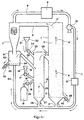
- FIG. 1 represents an example of installation, derived from the installations which are the subject of the documents cited above. It comprises a pre-reduction reactor 1 containing a circulating fluidized bed 2 formed from particles of iron ore being reduced, particles of metallic iron resulting from this reduction, and particles of semi-coke.
- a gas-permeable support 3, such as a grid, is placed at the bottom of the prereduction reactor 1 to prevent large particles from descending into the bottom of the reactor 1.
- a gas stream of fluidization crosses the assembly of the installation, and in particular the prereduction reactor 1, as symbolized by the arrows 4, 4 ′, 4 ".
- This fluidizing gas is a reducing gas, namely a CO / CO 2 / H 2 / H 2 O mixture which is injected at the base of reactor 1 through a pipe 5. It moves at a speed of the order of 2 to 10 m / s.
- the iron ore particles initially the oxidized natural state undergoes a reduction in metallic iron by the CO and the hydrogen of the fluidization gases.
- the gases and the solid particles escape from the prereduction reactor 1 via a pipe 6 and then enter a cyclone 7, in which they are separated from each other.
- the g az are discharged from the cyclone via a pipe 8, while the solid particles fall back into the lower part of the cyclone 7 and continue their journey in the installation, as will be explained below.
- the gases are purified from water vapor and from the CO 2 which they contain in an appropriate reactor 9 of a type known in itself, are returned by suitable means symbolized by the pump 10 and the pipe 11 towards the base of the reactor 1 after having passed through a preheater 12, and are again used for the fluidization and reduction of the ore inside the reactor 1.
- the installation also comprises, placed on the material circuit between the cyclone 7 and the pre-reduction reactor 1, a gasifier 13.
- a gasifier 13 This has the function of generating the gases used for the fluidization and to the circulation of particles, and to provide the energy necessary to balance the heat balance.
- injections of oxygen and carbonaceous materials, such as coal are carried out there, these carbonaceous materials being in excess.
- the temperature of the gases is of the order of 950 ° C., and the proportion of CO 2 and water vapor which they contain under steady conditions is around 30 to 40%.
- the carbonaceous materials 14 contained in a hopper 15, are introduced into the gasifier 13 through a line 16, and their admission is controlled by a valve 17.
- Oxygen, contained in a reservoir 18, is likewise blown into the gasifier 13 through a pipe 19, and its admission is controlled by a valve 20.
- CO is created by reaction of carbonaceous materials with the oxygen inside the gasifier 13. It is also possible, as proposed in the application FR 91 14467 already cited, form CO and hydrogen in a burner upstream of which lines 16 and 19 meet, so before the materials carbonaceous and oxygen do not enter the gasifier 13. This last configuration avoids reoxidation in the gasifier 13 of iron particles in contact with oxygen not yet combined with carbon. In the example shown, it is also at the gasifier 13 that place the introduction of new iron ore particles 21 in the material circuit. These particles are stored in a hopper 22 and introduced into the gasifier by a line 23 provided with a valve 24.
- the introduction into the gasifier 13 of the various solid particles and the formation of gases has the effect that in the gasifier 13, a fluidized bed 25 is formed solid particles, just like in the reactor of prereduction 1.
- the fluidization of particles is also provided by gases from a line 26, derived from line 11, and opening into the bottom of the gasifier 13.
- a gas permeable grid 27 prevents any particles too large to be fluidized only descend into line 26 and obstruct it.
- the gasifier 13 and the prereduction reactor 1 are connected by a pipe 28, and the gases and the particles composing the fluidized bed can thus circulate reactor to another.
- the solid matter resulting from the operation can be extracted from the installation so intermittent or continuous by means of a pipe 29 provided a valve 30 and connected to the base of the reactor prereduction 1.
- These materials usually consist of ore reduced to at least 75% and semi-coke, and are intended to be placed in a non-melting reactor shown where the cast iron will be produced.
- these material extraction means can be kept, but they will collect in priority particles too large to have been fluidized and which fell into the lower part of the reactor pre-reduction 1.
- the part bottom of cyclone 7 is directly connected to the gasifier 13, and the particles which were carried in the bed fluidized circulating before cyclone 7 therefore pass into the gasifier without distinction.
- the lower part of cyclone 7 leads into a third reactor 31 called “compartment of segregation ".
- this segregation compartment 31 we achieves gas circulation conditions such as particles of metallic iron and strongly iron ore reduced form the lower part of a dense fluidized bed 32, while the semi-coke and finer particles still little or not reduced ore particles are mostly driven by the gas stream, and pass in the gasifier 13 by using line 33 which connects to segregation compartment 31.
- the gases ensuring the fluidization of this dense bed 32 can advantageously (but not necessarily) also be taken from the pipe 11 and blown into the bottom of the segregation compartment 31 by a pipe 84.
- a gas permeable grid 34 placed in the lower part compartment 31 prevents particles from falling back into driving 84.
- Intermittent or continuous evacuation of materials making up the dense bed 32 is produced by a line 35 provided with a valve 36. These materials are therefore made up, for the most part, of metallic iron and very greatly reduced ore, and are ready to be placed in the fusion reactor.
- the compartment segregation 31 allows for efficient separation between iron and carbonaceous materials and thus limiting the quantity of carbonaceous materials which will be placed in the fusion reactor with iron ore strongly reduced and metallic iron.
- the exhaust pipe 29 usually present at the bottom of the pre-reduction reactor 1 can advantageously be kept to avoid possible accumulation in the bottom of reactor 1 of large agglomerated iron particles. It can also allow provide a product with higher carbon content than necessary that extracted at the level of segregation compartment 31 and can be mixed with it to optimize the conditions of operation of the fusion reactor.
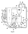
- FIG. 2 The configuration illustrated in Figure 2 is distinguishes, according to the invention, from that of FIG. 1 in that that the respective positions of the prereduction reactor and of the gasifier with respect to the cyclone are reversed, and in this that the segregation compartment is placed between the pre-reduction reactor and gasifier.
- the gasifier 37 receives, as in the example of the Figure 1, iron ore 38 stored in a hopper 39 and conveyed by a pipe 40 fitted with a valve 41, carbonaceous materials 42 stored in a hopper 43 and conveyed by a pipe 44 provided with a valve 45, and the oxygen stored in a container 46 and blown in by a line 47 provided with a valve 48.
- the gasifier 37 have therefore takes place the formation of CO and hydrogen and the circulation of bed 83 of ore particles and semi-coke. New ore begins to be reduced to wüstite.
- the solids and gas are directed through line 49 to cyclone 50 that separates them from each other.
- the gases are evacuated by line 51, decarbonated and dried in reactor 52, and returned by the pump 53 and the line 54 to the base of the various reactors of the installation to ensure the fluidization of solid particles, after passing through the preheater 55.
- solids, ore in process reduction and semi-coke they pass from cyclone 50 in the reduction reactor 56. They are fluidized there by gases (mainly CO and hydrogen) brought to the bottom of the reactor 56 via line 57, gases which are also used for complete the reduction of metallic iron ore.
- gases mainly CO and hydrogen
- the fluidization of the particles in the reactor 56 is made so as to form a bed circulating, which is sent by a pipe 60 in a segregation compartment 61. This compartment receives also, in its lower part, reducing gases of preferably taken from line 54 through line 62, and is fitted with a gas permeable grille 63.
- the conditions hydrodynamics in this compartment 61 are such that the highly reduced iron and ore particles form a dense bed 64 in its lower part, while the carbonaceous matter and fine particles of ore not still reduced remain fluidized in the upper part from reactor 61 above dense bed 64, and are sent by overflow using a line 65 in the gasifier 37 to continue their treatment.
- like gases are preferably highly reducing, they contribute to the completion of the ore reduction.
- the particles making up the lower part of the fluidized layer 64 are extracted continuously or intermittently by the line 66 provided with a valve 67, and are directed towards the fusion reactor for the production of pig iron.
- the rest of the purified gases circulating in line 54 can be directed through line 68 to the base of the gasifier 37, which has in its lower part a grid 69 avoiding blockage of the pipe 68 by any large particles present in the gasifier 37.
- This configuration like the previous one, allows you to considerably limit the amount of metallic iron circulating in the gasifier 37, since it is mostly retained in the segregation compartment 61.
- the configuration of Figure 2 where the compartment segregation is placed between the pre-reduction reactor and the gasifier, has the advantage of preventing particles of metallic iron do not pass in large quantities through the cyclone.
- the cyclone is indeed a place where, because of the high energies that are communicated to particles, risk of sticking freshly reduced iron particles the walls of the installation are particularly large. And these collages are of course to be avoided, because of the loss installation performance and deterioration of its organs they cause.
- Figure 3 shows a variant of the installation according to the invention which is similar to the previous one as to relative positions of the gasifier, the cyclone and the ore pre-reduction and segregation reactors solids.
- Figure installation organs 2 that end up with functions and configurations identical on the installation of figure 3 are marked there by the same references.
- the peculiarity of this facility is that ore reduction operations of iron and solid matter segregation, resulting in extracting a mixture very rich in iron particles metal, are combined in a single reactor 70 where the solid particles from cyclone 50 form a bed dense 71.
- the reduction reactor and segregation 70 is divided into three compartments 72, 73, 74 by transverse partitions 75, 76 which leave free the upper zone of the reactor 70.
- Lines 77, 78, 79 stuck on the pipe 54 send in these three purified and heated reducing gas compartments so to ensure the fluidization of all the particles and the iron ore reduction.
- first two compartments 72, 73 fluidization and time are ensured of residence of the various approximately uniform particles, in seeking above all the reduction of iron ore always mixed with semi-coke which prevents sticking of iron particles.
- Particles pass from compartment to the other by overflowing above partitions 75 and 76, and the finest are easily dragged downstream of the installation.
- the last compartment 74 we impose a lower fluidization speed, which has the effect to accentuate the segregation of the different species of particles according to their density.
- the lightest (semi-coke, ore not yet reduced) then make up mainly the upper part of the dense bed 71 and return by overflow into the gasifier 37, thanks to a line 80.
- the heaviest namely metallic iron, mainly make up the lower part of the dense bed 71 and can be discharged intermittently or continues through a pipe 81 provided with a valve 82 in direction of the fusion reactor.
- the division of the reactor 70 into compartments 72, 73, 74 where we mainly seek to reduce the iron ore for the first compartments, i.e. segregation of metallic iron for the latter, allows operate the plant with greater efficiency only if reactor 70 had only one compartment where operating conditions should be a compromise between the optimal conditions for each of these two functions. Indeed, the efficiency of the operation of segregation carried out in the last compartment 74 is all the greater as it is executed on particles of more homogeneous dimensions. And it's this homogenization that the division of reactor 70 into multiple compartments at adapted hydrodynamic conditions allows to approach. However, if we seek greater simplicity in the construction of the installation or if you do not wish to obtain a final product very low in semi-coke, we can content with a single compartment 70 reactor which would ensure both the reduction of the ore and the metallic iron segregation.
- the number of reactor compartments 70 can be changed (it can be two only, or at opposite greater than three), the main thing being that the last compartment at least be dedicated primarily to segregation of metallic iron particles.
Abstract
Description
L'invention concerne le domaine de la réduction du minerai de fer, notamment dans des installations fonctionnant avec un lit fluidisé circulant.The invention relates to the field of reduction of iron ore, especially in facilities operating with a circulating fluidized bed.
Actuellement, des recherches sont activement conduites afin de mettre au point des procédés sidérurgiques qui pourraient se substituer au haut-fourneau. Les inconvénients du haut-fourneau que de tels procédés visent à éliminer sont son manque de souplesse de fonctionnement, et la nécessité de lui associer une cokerie et une installation d'agglomération du minerai de fer. Par ailleurs, il faudrait que les nouveaux procédés conservent les excellentes performances énergétiques du haut fourneau.Currently, research is actively conducted in order to develop steel processes which could replace the blast furnace. The inconvenients from the blast furnace that such processes aim to eliminate are its lack of operational flexibility, and the need to associate him with a coking plant and an agglomeration facility iron ore. In addition, the new processes maintain excellent energy performance from the blast furnace.
Ces nouveaux procédés sont souvent désignés par le terme : procédés de "fusion réduction" ou "smelting reduction". L'un d'entre eux associe deux réacteurs. L'un de ces réacteurs produit à partir de minerai de fer du minerai très fortement réduit à l'état métallique, qui est enfourné dans le deuxième réacteur pour être transformé en fonte liquide. Les circuits gazeux de ces deux réacteurs peuvent être liés l'un à l'autre, ou être totalement indépendants.These new processes are often designated by the term: "fusion reduction" or "smelting" processes reduction ". One of them combines two reactors. One of these reactors produced from iron ore ore very greatly reduced to the metallic state, which is placed in the oven in the second reactor to be transformed into cast iron liquid. The gas circuits of these two reactors can be related to each other, or be completely independent.
Une forme de réalisation particulière d'un tel procédé est décrite par exemple dans le Brevet Européen EP 255180 et dans la Demande de brevet français n° 91.14467. La réaction de réduction du minerai de fer s'effectue en faisant réagir un lit fluidisé circulant, formé par des particules de minerai en cours de réduction et de semi-coke, avec un gaz réducteur (mélange CO/CO2/H2/H2O) qui assure également la fluidisation des matières solides. Celle-ci a lieu dans une première partie du réacteur. Les gaz chargés en particules de minerai en cours de réduction et de semi-coke passent ensuite dans un cyclone. Les gaz s'échappent alors du réacteur, tandis que les particules descendent dans un gazéifieur, où sont introduits séparément ou ensemble du charbon et de l'oxygène dans le but de former du CO et de l'hydrogène qui vont contribuer à la réduction du minerai. Les matières solides et les gaz reviennent ensuite dans la première partie du réacteur, d'où une fraction des matières solides (minerai réduit et semi-coke) est extraite périodiquement ou continûment. Du minerai neuf est introduit dans le courant de matières entre le cyclone et le gazéifieur. Les gaz qui se sont échappés du cyclone sont épurés et réintroduits dans le gazéifieur et à la base de la première partie du réacteur, où ils peuvent rejouer leur rôle de milieu fluidisant et réactionnel.A particular embodiment of such a process is described for example in European Patent EP 255,180 and in French Patent Application No. 91.14467. The reduction reaction of the iron ore is carried out by reacting a circulating fluidized bed, formed by particles of ore being reduced and of semi-coke, with a reducing gas (mixture CO / CO 2 / H 2 / H 2 O) which also ensures the fluidization of solid materials. This takes place in the first part of the reactor. The gases loaded with particles of ore being reduced and semi-coke then pass through a cyclone. The gases then escape from the reactor, while the particles descend into a gasifier, where carbon or oxygen are introduced separately or together in order to form CO and hydrogen which will contribute to the reduction of the ore. The solids and gases then return to the first part of the reactor, from which a fraction of the solids (reduced ore and semi-coke) is extracted periodically or continuously. New ore is introduced into the material stream between the cyclone and the gasifier. The gases which have escaped from the cyclone are purified and reintroduced into the gasifier and at the base of the first part of the reactor, where they can replay their role of fluidizing and reaction medium.
Les matières solides extraites du réacteur de réduction qui vient d'être décrit sont ensuite dirigées vers le réacteur de fusion pour contribuer à y produire de la fonte liquide. Comme on l'a dit, ces matières sont composées pour l'essentiel d'un mélange de minerai de fer fortement réduit (à environ 75 % au moins) et de semi-coke avec accessoirement d'autres matières non ferreuses : impuretés provenant du minerai et additifs éventuels. Leur teneur en semi-coke (qui peut atteindre 50 %) est en fait supérieure à celle qui est nécessaire pour former la fonte (de l'ordre de 5 à 25 %). Cela conduirait à une production excessive de gaz carbonés dans le réacteur de fusion, et à une forte consommation de matières carbonées de l'ensemble de l'installation, consommation qu'il est souhaitable d'abaisser. Il faut donc développer des moyens permettant une sortie sélective du fer métallisé et du semi-coke afin de pouvoir régler les teneurs en carbone du lit fluidisé et du produit extrait du réacteur de réduction à des niveaux différents et compatibles avec un bon fonctionnement des réacteurs de réduction et de fusion. Le document US2.742.354 propose à cet effet d'insérer sur le circuit de matières solides un lit dense de ségrégation où les particules de fer peuvent être extraites de l'installation de manière privilégiée, accompagnées d'une quantité minimale de matières carbonées. Ce lit dense est placé en amont de la zone où sont créés les gaz réducteurs.Solids extracted from the reduction reactor which has just been described are then directed to the fusion reactor to help produce cast iron liquid. As we said, these materials are composed for the essence of a greatly reduced iron ore mixture (at least about 75%) and semi-coke with incidentally other non-ferrous materials: impurities from ore and any additives. Their semi-coke content (which can reach 50%) is actually higher than necessary to form cast iron (around 5 to 25%). This would lead to excessive production of carbonaceous gases in the fusion reactor, and a high consumption of carbonaceous materials from the entire installation, consumption which it is desirable to lower. Must therefore develop means for selective iron release metallized and semi-coke in order to be able to adjust the contents carbon of the fluidized bed and of the product extracted from the reactor reduction at different levels and compatible with a correct operation of reduction and fusion reactors. Document US2,742,354 proposes for this purpose to insert on the solids circuit a dense bed of segregation where iron particles can be extracted from privileged installation, accompanied by a minimum quantity of carbonaceous matter. This dense bed is placed upstream of the zone where the reducing gases are created.
Un autre problème posé par une telle installation est
que les particules de fer en circulation transitent
massivement par le gazéifieur, où elles risquent d'être
réoxydées par l'oxygène qui y est injecté. Cela conduit à une
diminution du rendement de l'installation. D'autre part, ces
particules de fer risquent de se coller aux parois du
réacteur, en particulier dans les zones à forte agitation
telles que le cyclone. Il importe donc que, une fois
obtenues, ces particules de fer métallique séjournent le
moins longtemps possible dans le réacteur.
Le but de l'invention est de proposer un procédé de réduction
du minerai de fer fondé sur les principes décrits
précédemment, et permettant d'une part de diminuer
considérablement la quantité de fer métallique passant dans
le gazéifieur, et d'autre part d'enrichir en fer métallique
les matières extraites de l'installation.
A cet effet, l'invention a pour objetAnother problem posed by such an installation is that the circulating iron particles pass massively through the gasifier, where they risk being reoxidized by the oxygen which is injected there. This leads to a decrease in the efficiency of the installation. On the other hand, these iron particles risk sticking to the walls of the reactor, in particular in areas with strong agitation such as the cyclone. It is therefore important that, once obtained, these metallic iron particles remain as short as possible in the reactor.
The object of the invention is to propose a process for the reduction of iron ore based on the principles described above, and which makes it possible on the one hand to considerably reduce the quantity of metallic iron passing through the gasifier, and on the other hand to enrich the materials extracted from the installation with metallic iron.
To this end, the subject of the invention is
Installation de réduction du minerai de fer parcourue par un courant de particules solides et comprenant :
- des moyens d'introduction de particules de minerai de fer dans ladite installation ;
- un réacteur de préréduction contenant un lit de particules, notamment de minerai de fer en cours de réduction, pourvu de moyens pour fluidiser ledit lit, et comportant un dispositif d'injection de gaz réducteur contenant du CO et de l'hydrogène dans ledit réacteur de préréduction (56, 70), ledit gaz assurant la fluidisation dudit lit de particules (59, 71) ;
- un réacteur de gazéification (37) comprenant des moyens de production de CO et d'hydrogène à partir de matières carbonées (42) et d'oxygène, les particules solides présentes dans ledit réacteur (37) formant un lit fluidisé circulant (83) ;
- des moyens (50) de séparation dudit gaz réducteur et des particules qu'il transporte, et des moyens de renvoi dudit gaz réducteur ainsi épuré dans ledit réacteur de préréduction (56, 70) ;
- des moyens d'extraction des particules, notamment de fer métallique, produites par l'installation, comprenant un lit fluidisé dense de particules (64, 74) assurant une ségrégation desdites particules de fer métallique ;
- des moyens pour faire communiquer ledit réacteur de préréduction (56, 70) et un compartiment de ségrégation pourvu de moyens (62, 79) pour y former ledit lit fluidisé dense (64, 74) et de moyens (66, 67, 81, 82) d'extraction desdites particules dudit lit dense (64, 74) ;
- ledit réacteur de gazéification (37) renfermant ledit lit fluidisé circulant (83) de particules solides ;
- lesdits moyens de séparation (50) dudit gaz réducteur et des particules qu'il transporte ;
- une conduite (49) faisant communiquer ledit réacteur de gazéification (37) avec lesdits moyens (50) de séparation desdites particules et dudit gaz réducteur sortant du réacteur de gazéification (37) ;
- ledit réacteur de préréduction (56, 70) recueillant lesdites particules sortant desdits moyens de séparation (50) et renfermant ledit lit fluidisé circulant (59, 71, 72) ;
- lesdits moyens pour faire communiquer ledit réacteur de préréduction (56, 70) et un compartiment de ségrégation pourvu de moyens (62, 79) pour y former ledit lit fluidisé dense (64, 74) et de moyens (66, 67, 81, 82) d'extraction desdites particules dudit lit dense (64, 74) ;
- et une conduite (65, 80) faisant communiquer ledit compartiment de ségrégation et ledit réacteur de gazéification (37), de manière à y amener les gaz et les particules solides s'échappant dudit compartiment de ségrégation.
- means for introducing iron ore particles into said installation;
- a pre-reduction reactor containing a bed of particles, in particular iron ore being reduced, provided with means for fluidizing said bed, and comprising a device for injecting reducing gas containing CO and hydrogen in said reactor pre-reduction (56, 70), said gas ensuring the fluidization of said bed of particles (59, 71);
- a gasification reactor (37) comprising means for producing CO and hydrogen from carbonaceous materials (42) and oxygen, the solid particles present in said reactor (37) forming a circulating fluidized bed (83);
- means (50) for separating said reducing gas and the particles which it transports, and means for returning said reducing gas thus purified to said prereduction reactor (56, 70);
- means for extracting particles, in particular of metallic iron, produced by the installation, comprising a dense fluidized bed of particles (64, 74) ensuring segregation of said particles of metallic iron;
- means for communicating said pre-reduction reactor (56, 70) and a segregation compartment provided with means (62, 79) for forming said dense fluidized bed (64, 74) and means (66, 67, 81, 82 ) extracting said particles from said dense bed (64, 74);
- said gasification reactor (37) enclosing said circulating fluidized bed (83) of solid particles;
- said means for separating (50) said reducing gas and the particles which it transports;
- a pipe (49) communicating said gasification reactor (37) with said means (50) for separating said particles and said reducing gas leaving the gasification reactor (37);
- said pre-reduction reactor (56, 70) collecting said particles leaving said separation means (50) and enclosing said circulating fluidized bed (59, 71, 72);
- said means for communicating said pre-reduction reactor (56, 70) and a segregation compartment provided with means (62, 79) for forming said dense fluidized bed (64, 74) and means (66, 67, 81, 82 ) extracting said particles from said dense bed (64, 74);
- and a pipe (65, 80) communicating said segregation compartment and said gasification reactor (37), so as to bring therein the gases and the solid particles escaping from said segregation compartment.
L'invention sera mieux comprise à la lecture de la description qui suit, faisant référence aux figures annexées suivantes :
- la figure 1 qui montre schématiquement un premier exemple d'installation de réduction du minerai de fer qui ne fait partie de l'invention ;
- la figure 2 qui montre un premier exemple d'une installation selon l'invention ;
- la figure 3 qui montre un deuxième exemple d'une telle installation.
- FIG. 1 which schematically shows a first example of an iron ore reduction installation which is not part of the invention;
- Figure 2 which shows a first example of an installation according to the invention;
- Figure 3 which shows a second example of such an installation.
La variante de la figure 1 représente un exemple
d'installation, dérivé des installations qui sont l'objet des
documents précédemment cités. Elle comprend un réacteur de
préréduction 1 renfermant un lit fluidisé circulant 2 formé
de particules de minerai de fer en cours de réduction, de
particules de fer métallique résultant de cette réduction, et
des particules de semi-coke. Un support 3 perméable aux gaz,
tel qu'une grille, est placé à la partie inférieure du
réacteur de préréduction 1 pour éviter que des particules de
grosse taille ne descendent dans le fond du réacteur 1. Un
courant gazeux de fluidisation traverse l'ensemble de
l'installation, et notamment le réacteur de préréduction 1,
comme le symbolisent les flèches 4, 4', 4". Ce gaz de
fluidisation est un gaz réducteur, à savoir un mélange
CO/CO2/H2/H2O qui est injecté à la base du réacteur 1 par une
conduite 5. Il se déplace à une vitesse de
l'ordre de 2 à 10 m/s. Au cours de leur cheminement dans le
réacteur 1, les particules de minerai de fer initialement à
l'état naturel oxydé subissent une réduction en fer
métallique par le CO et l'hydrogène des gaz de fluidisation.
Les gaz et les particules solides s'échappent du réacteur de
préréduction 1 par une conduite 6 et pénètrent ensuite dans
un cyclone 7, dans lequel ils sont séparés les uns des
autres. Les gaz sont évacués du cyclone par une conduite 8,
alors que les particules solides retombent dans la partie
inférieure du cyclone 7 et poursuivent leur parcours dans
l'installation, comme on l'expliquera plus loin. Après leur
sortie du cyclone les gaz sont épurés de la vapeur d'eau et
du CO2 qu'ils contiennent dans un réacteur approprié 9 d'un
type connu en lui-même, sont renvoyés par des moyens adaptés
symbolisés par la pompe 10 et la conduite 11 vers la base du
réacteur 1 après être passés par un préchauffeur 12, et sont
à nouveau utilisés pour la fluidisation et la réduction du
minerai à l'intérieur du réacteur 1.The variant of FIG. 1 represents an example of installation, derived from the installations which are the subject of the documents cited above. It comprises a pre-reduction reactor 1 containing a circulating
Conformément à l'Art Antérieur cité, l'installation
comporte également, placé sur le circuit des matières entre
le cyclone 7 et le réacteur de préréduction 1, un gazéifieur
13. Celui-ci a pour fonctions de générer les gaz servant à la
fluidisation et à la circulation des particules, et de
fournir l'énergie nécessaire à l'équilibre du bilan
thermique. A cet effet, on y réalise des injections d'oxygène
et de matières carbonées, telles que du charbon, ces matières
carbonées étant en excès. On forme ainsi du CO et de
l'hydrogène (avec une certaine proportion de CO2 et de vapeur
d'eau) qui vont réagir avec le minerai pour le réduire en fer
et s'oxyder eux-mêmes en CO2 et vapeur d'eau, alors que le
charbon en excès se transforme en semi-coke. La température
des gaz est de l'ordre de 950°C, et la proportion de CO2 et
de vapeur d'eau qu'ils contiennent en régime permanent est
d'environ 30 à 40 %.In accordance with the cited prior art, the installation also comprises, placed on the material circuit between the cyclone 7 and the pre-reduction reactor 1, a
Les matières carbonées 14 contenues dans une trémie 15,
sont introduites dans le gazéifieur 13 par une conduite 16,
et leur admission est commandée par une vanne 17. L'oxygène,
contenu dans un réservoir 18, est de même insufflé dans le
gazéifieur 13 par une conduite 19, et son admission est
commandée par une vanne 20. Dans cette forme de réalisation,
le CO est créé par réaction des matières carbonées avec
l'oxygène à l'intérieur du gazéifieur 13. On peut également,
comme proposé dans la demande FR 91 14467 déjà citée, former
le CO et l'hydrogène dans un brûleur en amont duquel les
conduites 16 et 19 se rejoignent, donc avant que les matières
carbonées et l'oxygène ne pénètrent dans le gazéifieur 13.
Cette dernière configuration permet d'éviter la réoxydation
dans le gazéifieur 13 de particules de fer au contact de
l'oxygène non encore combiné au carbone. Dans l'exemple
représenté, c'est également au niveau du gazéifieur 13 qu'a
lieu l'introduction de particules de minerai de fer neuf 21
dans le circuit des matières. Ces particules sont stockées
dans une trémie 22 et introduites dans le gazéifieur par une
conduite 23 munie d'une vanne 24.The
L'introduction dans le gazéifieur 13 des diverses
particules solides et la formation des gaz a pour effet que
dans le gazéifieur 13, il se forme un lit fluidisé 25 de
particules solides, tout comme dans le réacteur de
préréduction 1. Optionnellement, la fluidisation des
particules est également assurée par des gaz provenant d'une
conduite 26, dérivée de la conduite 11, et débouchant dans le
fond du gazéifieur 13. Une grille 27 perméable aux gaz
empêche que d'éventuelles particules trop grosses pour être
fluidisées ne descendent jusque dans la conduite 26 et
l'obstruent.The introduction into the
Le gazéifieur 13 et le réacteur de préréduction 1 sont
reliés par une conduite 28, et les gaz et les particules
composant le lit fluidisé peuvent ainsi circuler d'un
réacteur à l'autre. Dans l'installation selon l'Art
Antérieur, les matières solides résultant de l'opération
peuvent être extraites de l'installation de manière
intermittente ou continue au moyen d'une conduite 29 munie
d'une vanne 30 et connectée à la base du réacteur de
préréduction 1. Ces matières se composent habituellement de
minerai réduit à 75 % au moins et de semi-coke, et sont
destinées à être enfournées dans un réacteur de fusion non
représenté où sera fabriquée la fonte. Dans l'installation
selon l'invention, ces moyens d'extraction des matières
peuvent être conservés, mais ils recueilleront en priorité
les particules trop grosses pour avoir été fluidisées et qui
sont tombées dans la partie inférieure du réacteur de
préréduction 1.The
Dans des installations selon l'Art Antérieur, la partie
inférieure du cyclone 7 est reliée directement au gazéifieur
13, et les particules qui étaient véhiculées dans le lit
fluidisé circulant avant le cyclone 7 passent donc dans le
gazéifieur de manière indifférenciée. Au contraire, dans
l'exemple de la figure 1, la partie inférieure du cyclone 7
débouche dans un troisième réacteur 31 dit "compartiment de
ségrégation". Dans ce compartiment de ségrégation 31, on
réalise des conditions de circulation d'un gaz telles que les
particules de fer métallique et de minerai de fer fortement
réduit forment la partie inférieure d'un lit fluidisé dense
32, alors que les particules de semi-coke et les plus fines
particules de minerai encore peu ou pas réduit sont
majoritairement entraínées par le courant gazeux, et passent
dans le gazéifieur 13 en empruntant la conduite 33 qui le
relie au compartiment de ségrégation 31. Les gaz assurant la
fluidisation de ce lit dense 32 peuvent avantageusement (mais
non obligatoirement) être eux aussi prélevés sur la conduite
11 et insufflés dans le fond du compartiment de ségrégation
31 par une conduite 84. Ainsi la réduction du minerai de fer
peut être parachevée à l'intérieur du lit dense 32. Une
grille perméable aux gaz 34 placée dans la partie inférieure
du compartiment 31 empêche les particules de redescendre dans
la conduite 84. L'évacuation intermittente ou continue des
matières composant le lit dense 32 est réalisée par une
conduite 35 munie d'une vanne 36. Ces matières sont donc
constituées, pour leur plus grande part, de fer métallique et
de minerai très fortement réduit, et sont prêtes à être
enfournées dans le réacteur de fusion. Le compartiment de
ségrégation 31 permet de réaliser une séparation efficace
entre les matières ferrifères et les matières carbonées et
ainsi de limiter la quantité de matières carbonées qui seront
enfournées dans le réacteur de fusion avec le minerai de fer
fortement réduit et le fer métallique.In prior art installations, the part
bottom of cyclone 7 is directly connected to the
Comme on l'a dit la conduite d'évacuation 29
habituellement présente au bas du réacteur de préréduction 1
peut avantageusement être conservée afin d'éviter une
accumulation éventuelle dans le fond du réacteur 1 de grosses
particules ferrifères agglomérées. Elle peut aussi permettre
de fournir si nécessaire un produit plus riche en carbone que
celui extrait au niveau du compartiment de ségrégation 31 et
pouvant lui être mélangé pour optimiser les conditions de
marche du réacteur de fusion.As we said the
La configuration exemplifiée sur la figure 2 se distingue, selon l'invention, de celle de la figure 1 en ce que les positions respectives du réacteur de préréduction et du gazéifieur par rapport au cyclone sont inversées, et en ce que le compartiment de ségrégation se trouve placé entre le réacteur de préréduction et le gazéifieur.The configuration illustrated in Figure 2 is distinguishes, according to the invention, from that of FIG. 1 in that that the respective positions of the prereduction reactor and of the gasifier with respect to the cyclone are reversed, and in this that the segregation compartment is placed between the pre-reduction reactor and gasifier.
Le gazéifieur 37, reçoit, comme dans l'exemple de la
figure 1, du minerai de fer 38 stocké dans une trémie 39 et
convoyé par une conduite 40 munie d'une vanne 41, des
matières carbonées 42 stockées dans une trémie 43 et
convoyées par une conduite 44 munie d'une vanne 45, et de
l'oxygène stocké dans un récipient 46 et insufflé par une
conduite 47 munie d'une vanne 48. Dans le gazéifieur 37 ont
donc lieu la formation du CO et de l'hydrogène et la mise en
circulation du lit 83 de particules de minerai et de semi-coke.
Le minerai neuf y commence à être réduit en wüstite. A
leur sortie du gazéifieur 37, les matières solides et
gazeuses sont dirigées par la conduite 49 vers le cyclone 50
qui les sépare les unes des autres. Les gaz sont évacués par
la conduite 51, décarbonatés et séchés dans le réacteur 52,
et renvoyés par la pompe 53 et la conduite 54 à la base des
divers réacteurs de l'installation pour assurer la
fluidisation des particules solides, après être passés par le
préchauffeur 55.The
Quant aux matières solides, minerai en cours de
réduction et semi-coke, elles passent du cyclone 50 dans le
réacteur de réduction 56. Elles y sont fluidisées par les gaz
(principalement CO et hydrogène) amenés dans le fond du
réacteur 56 par la conduite 57, gaz qui servent également à
parachever la réduction du minerai en fer métallique. Une
grille perméable aux gaz 58 barrant le fond du réacteur 56
évite que les particules non fluidisées ne viennent boucher
la conduite 57. La fluidisation des particules dans le
réacteur 56 est réalisée de manière à former un lit
circulant, qui est envoyé par une conduite 60 dans un
compartiment de ségrégation 61. Ce compartiment reçoit lui
aussi, dans sa partie inférieure, des gaz réducteurs de
préférence prélevés sur la conduite 54 par une conduite 62,
et est muni d'une grille perméable aux gaz 63. Les conditions
hydrodynamiques dans ce compartiment 61 sont telles que les
particules de fer et de minerai fortement réduit forment un
lit dense 64 dans sa partie inférieure, alors que les
matières carbonées et les fines particules de minerai non
encore réduit demeurent fluidisées dans la partie supérieure
du réacteur 61 au-dessus du lit dense 64, et sont envoyées
par trop-plein à l'aide d'une conduite 65 dans le gazéifieur
37 pour y poursuivre leur traitement. De plus, comme les gaz
de fluidisation sont de préférence fortement réducteurs, ils
contribuent au parachèvement de la réduction du minerai. Les
particules composant la partie basse de la couche fluidisée
64 sont extraites de manière continue ou intermittente par la
conduite 66 munie d'une vanne 67, et sont dirigées vers le
réacteur de fusion pour la production de fonte.As for solids, ore in process
reduction and semi-coke, they pass from
Le restant des gaz épurés circulant dans la conduite 54
peut être dirigé par la conduite 68 vers la base du
gazéifieur 37, qui comporte dans sa partie inférieure une
grille 69 évitant le bouchage de la conduite 68 par
d'éventuelles particules de forte taille présentes dans le
gazéifieur 37.The rest of the purified gases circulating in
Cette configuration, comme la précédente, permet de
limiter considérablement la quantité de fer métallique
circulant dans le gazéifieur 37, puisqu'il est
majoritairement retenu dans le compartiment de ségrégation
61. This configuration, like the previous one, allows you to
considerably limit the amount of metallic iron
circulating in the
On peut également prévoir une possibilité d'évacuation
d'une portion des particules composant le lit circulant 59
dans le réacteur de préréduction 56, au moyen d'une conduite
70 munie d'une vanne 71, pour les mêmes raisons que celles
exposées dans la description de l'installation de la
figure 1.We can also provide a possibility of evacuation
of a portion of the particles making up the circulating
Par rapport à la configuration de la figure 1 où le compartiment de ségrégation suit immédiatement le cyclone, la configuration de la figure 2, où le compartiment de ségrégation est placé entre le réacteur de préréduction et le gazéifieur, présente l'avantage d'éviter que des particules de fer métallique ne transitent en grande quantité par le cyclone. Le cyclone est en effet un endroit où, du fait des hautes énergies qui sont communiquées aux particules, les risques de collage des particules de fer fraíchement réduites aux parois de l'installation sont particulièrement grands. Et ces collages sont bien entendu à éviter, à cause de la perte de rendement de l'installation et de la détérioration de ses organes qu'ils provoquent.Compared to the configuration of Figure 1 where the segregation compartment immediately follows the cyclone, the configuration of Figure 2, where the compartment segregation is placed between the pre-reduction reactor and the gasifier, has the advantage of preventing particles of metallic iron do not pass in large quantities through the cyclone. The cyclone is indeed a place where, because of the high energies that are communicated to particles, risk of sticking freshly reduced iron particles the walls of the installation are particularly large. And these collages are of course to be avoided, because of the loss installation performance and deterioration of its organs they cause.
La figure 3 montre une variante de l'installation selon
l'invention qui s'apparente à la précédente quant aux
positions relatives du gazéifieur, du cyclone et des
réacteurs de préréduction du minerai et de ségrégation des
matières solides. Les organes de l'installation de la figure
2 qui se retrouvent avec des fonctions et des configurations
identiques sur l'installation de la figure 3 y sont repérés
par les mêmes références. La particularité de cette
installation est que les opérations de réduction du minerai
de fer et de ségrégation de matières solides, aboutissant à
l'extraction d'un mélange très riche en particules de fer
métallique, sont regroupées dans un réacteur unique 70 où les
particules solides provenant du cyclone 50 forment un lit
dense 71. Dans l'exemple représenté, le réacteur de réduction
et de ségrégation 70 est divisé en trois compartiments 72,
73, 74 par des cloisons transversales 75, 76 qui laissent
libre la zone supérieure du réacteur 70. Des conduites 77,
78, 79 piquées sur la conduite 54 envoient dans ces trois
compartiments des gaz réducteurs épurés et réchauffés afin
d'assurer la fluidisation de l'ensemble des particules et la
réduction du minerai de fer. Dans les deux premiers
compartiments 72, 73, on assure une fluidisation et un temps
de séjour des diverses particules à peu près uniformes, en
recherchant avant tout la réduction du minerai de fer
toujours mélangé au semi-coke qui évite le collage des
particules de fer. Les particules passent d'un compartiment à
l'autre par débordement au-dessus des cloisons 75 et 76, et
les plus fines sont facilement entraínées vers l'aval de
l'installation. Dans le dernier compartiment 74, on impose
une vitesse de fluidisation moindre, ce qui a pour effet
d'accentuer la ségrégation des différentes espèces de
particules en fonction de leur densité. Les plus légères
(semi-coke, minerai non encore réduit) composent alors
majoritairement la partie supérieure du lit dense 71 et
retournent par débordement dans le gazéifieur 37, grâce à une
conduite 80. Les plus lourdes, à savoir le fer métallique,
composent majoritairement la partie inférieure du lit dense
71 et peuvent être évacuées de manière intermittente ou
continue par une conduite 81 munie d'une vanne 82 en
direction du réacteur de fusion.Figure 3 shows a variant of the installation according to
the invention which is similar to the previous one as to
relative positions of the gasifier, the cyclone and the
ore pre-reduction and segregation reactors
solids.
La division du réacteur 70 en compartiments 72, 73, 74
où on recherche de manière prépondérante soit la réduction du
minerai de fer pour les premiers compartiments, soit la
ségrégation du fer métallique pour le dernier, permet de
faire fonctionner l'installation avec une plus grande
efficacité que si le réacteur 70 ne comportait qu'un seul
compartiment où les conditions de fonctionnement devraient
être un compromis entre les conditions optimales pour chacune
de ces deux fonctions. En effet, l'efficacité de l'opération
de ségrégation réalisée dans le dernier compartiment 74 est
d'autant plus grande qu'elle est exécutée sur des particules
de dimensions plus homogènes. Et c'est cette homogénéisation
que la division du réacteur 70 en multiples compartiments aux
conditions hydrodynamiques adaptées permet d'approcher.
Toutefois, si on recherche une plus grande simplicité dans la
construction de l'installation ou si on ne désire pas obtenir
un produit final très pauvre en semi-coke, on peut se
contenter d'un réacteur 70 à un seul compartiment qui
assurerait à la fois la réduction du minerai et la
ségrégation du fer métallique.The division of the
Il va de soi que le nombre de compartiments du réacteur
70 peut être modifié (il peut être de deux seulement, ou au
contraire supérieur à trois), l'essentiel étant que le dernier
compartiment au moins soit dédié prioritairement à la
ségrégation des particules de fer métallique.It goes without saying that the number of
Claims (5)
- Plant for the reduction of iron ore, through which a stream of solid particles flows, this plant comprising:characterized in that the said plant comprises, in succession along the path of the said solid particles:means (39, 40, 41) for introducing particles of iron ore (38) into the said plant;a prereduction reactor (56, 70) containing a bed of particles (59, 71, 72), especially particles of iron ore undergoing reduction, which is provided with means for fluidizing the said bed and includes a device (57, 77, 78, 79) for injecting a reducing gas containing CO and hydrogen into the said prereduction reactor (56, 70), the said gas fluidizing the said bed of particles (59, 71);a gasification reactor (37) comprising means for producing CO and hydrogen from carbonaceous materials (42) and from oxygen, the solid particles present in the said reactor (37) forming a circulating fluidized bed (83);means (50) for separating the said reducing gas from the particles that it transports, and means for sending the said reducing gas thus purified back into the said prereduction reactor (56, 70);means for extracting the particles, especially particles of metallic iron, which are produced by the plant, comprising a dense fluidized bed of particles (64, 74) ensuring segregation of the said particles of metallic iron;means for making the said prereduction reactor (56, 70) communicate with a segregation compartment which is provided with means (62, 79) for forming the said dense fluidized bed (64, 74) therein and which is provided with means (66, 67, 81, 82) for extracting the said particles from the said dense bed (64, 74);the said gasification reactor (37) containing the said circulating fluidized bed (83) of solid particles;the said means (50) for separating the said reducing gas from the particles that it transports;a pipe (49) making the said gasification reactor (37) communicate with the said means (50) for separating the said particles from the said reducing gas leaving the gasification reactor (37);the said prereduction reactor (56, 70) which collects the said particles leaving the said separation means (50) and which contains the said circulating fluidized bed (59, 71, 72);the said means for making the said prereduction reactor (56, 70) communicate with a segregation compartment which is provided with means (62, 79) for forming the said dense fluidized bed (64, 74) therein and which is provided with means (66, 67, 81, 82) for extracting the said particles from the said dense bed (64, 74);and a pipe (65, 80) making the said segregation compartment communicate with the said gasification reactor (37) so that the gases and the solid particles escaping from the said segregation compartment are taken into the said gasification reactor.
- Plant according to Claim 1, characterized in that the said segregation compartment constitutes a reactor (61) separate from the said prereduction reactor (56, 70).
- Plant according to Claim 1, characterized in that, in the said prereduction reactor (70) which collects the said solid particles leaving the said separation means (50), the said particles are fluidized so as to form the said dense fluidized bed (71) in which the reduction of the iron ore and the segregation of the particles take place, the said means (81, 82) for extracting the particles produced by the plant being connected to the said prereduction reactor (70).
- Plant according to Claim 3, characterized in that the prereduction reactor (70) comprises at least one transverse partition (75, 76) dividing the said prereduction reactor (70) into a plurality of compartments (72, 73, 74) communicating via their upper part, the said solid particles passing in succession through these compartments, each of the said compartments (72, 73, 74) having its own means (77, 78, 79) for fluidizing the solid particles that it contains, the means (79) for fluidizing at least the last compartment (74) being controlled so as to promote segregation of the particles that it contains according to their density, and the said means (81, 82) for extracting the particles being connected to the said last compartment (74).
- Plant according to one of Claims 1 to 4, characterized in that it comprises means (52) for decarbonizing and for dehydrating the gases leaving the separation means (50) and comprises means (53, 54, 57, 62, 68, 77, 78, 79, 84) for sending the said gases into the said prereduction reactors (56, 70) and/or the said gasification reactor (37) and/or the said segregation compartment (61, 70).
Applications Claiming Priority (2)
| Application Number | Priority Date | Filing Date | Title |
|---|---|---|---|
| FR9214487 | 1992-11-27 | ||
| FR9214487A FR2698637B1 (en) | 1992-11-27 | 1992-11-27 | Iron ore reduction installation using beds of solid particles fluidized by a reducing gas. |
Publications (2)
| Publication Number | Publication Date |
|---|---|
| EP0599760A1 EP0599760A1 (en) | 1994-06-01 |
| EP0599760B1 true EP0599760B1 (en) | 1999-06-02 |
Family
ID=9436124
Family Applications (1)
| Application Number | Title | Priority Date | Filing Date |
|---|---|---|---|
| EP93470030A Expired - Lifetime EP0599760B1 (en) | 1992-11-27 | 1993-11-16 | Installation for iron ore reduction in a bed of solid particles fluidized by a reducing gas |
Country Status (5)
| Country | Link |
|---|---|
| EP (1) | EP0599760B1 (en) |
| AT (1) | ATE180840T1 (en) |
| DE (1) | DE69325147T2 (en) |
| ES (1) | ES2133373T3 (en) |
| FR (1) | FR2698637B1 (en) |
Families Citing this family (2)
| Publication number | Priority date | Publication date | Assignee | Title |
|---|---|---|---|---|
| AT403168B (en) * | 1995-11-02 | 1997-11-25 | Voest Alpine Ind Anlagen | METHOD AND DEVICE FOR RETURNING A FINE-PARTICLE SOLID EXHAUSTED FROM A REACTOR VESSEL WITH A GAS |
| DE102007009759A1 (en) * | 2007-02-27 | 2008-08-28 | Outotec Oyj | Distribution of solid flow drawn-off from cyclone/fluidized bed container, by conducting solid flow over first down pipe and then fluidizing at bottom of down pipe by supplying carrier gas, and conveying a part of solid flow towards the top |
Family Cites Families (6)
| Publication number | Priority date | Publication date | Assignee | Title |
|---|---|---|---|---|
| US2742354A (en) * | 1954-11-01 | 1956-04-17 | Exxon Research Engineering Co | Iron ore reduction process |
| US2742353A (en) * | 1954-11-01 | 1956-04-17 | Exxon Research Engineering Co | Iron ore reduction process |
| DE1767628C3 (en) * | 1968-05-30 | 1985-03-14 | Metallgesellschaft Ag, 6000 Frankfurt | Process for performing endothermic processes |
| DE2524540C2 (en) * | 1975-06-03 | 1986-04-24 | Metallgesellschaft Ag, 6000 Frankfurt | Process for performing endothermic processes |
| DE3626027A1 (en) * | 1986-08-01 | 1988-02-11 | Metallgesellschaft Ag | METHOD FOR REDUCING FINE-GRAIN, IRON-CONTAINING MATERIALS WITH SOLID CARBONATED REDUCING AGENTS |
| FR2683829B1 (en) * | 1991-11-19 | 1994-07-22 | Siderurgie Fse Inst Rech | CIRCULATING FLUIDIZED BED IRON ORE REDUCTION TREATMENT PLANT. |
-
1992
- 1992-11-27 FR FR9214487A patent/FR2698637B1/en not_active Expired - Fee Related
-
1993
- 1993-11-16 DE DE69325147T patent/DE69325147T2/en not_active Expired - Fee Related
- 1993-11-16 AT AT93470030T patent/ATE180840T1/en not_active IP Right Cessation
- 1993-11-16 ES ES93470030T patent/ES2133373T3/en not_active Expired - Lifetime
- 1993-11-16 EP EP93470030A patent/EP0599760B1/en not_active Expired - Lifetime
Also Published As
| Publication number | Publication date |
|---|---|
| ES2133373T3 (en) | 1999-09-16 |
| DE69325147T2 (en) | 1999-12-23 |
| FR2698637A1 (en) | 1994-06-03 |
| DE69325147D1 (en) | 1999-07-08 |
| EP0599760A1 (en) | 1994-06-01 |
| FR2698637B1 (en) | 1995-01-27 |
| ATE180840T1 (en) | 1999-06-15 |
Similar Documents
| Publication | Publication Date | Title |
|---|---|---|
| EP0093063B1 (en) | Process and device for controlling the temperature of a reaction carried out in a fluidized bed | |
| EP0161970B1 (en) | Method and installation for the treatment of material in a circulating fluidized bed | |
| EP0173782B1 (en) | Process for treating materials | |
| EP0692543A1 (en) | Process for producing sponge iron with low sulfur content | |
| FR2587717A1 (en) | PROCESS FOR PRODUCING A PURE GAS CONTAINING CARBON OXIDE AND HYDROGEN | |
| EP0599760B1 (en) | Installation for iron ore reduction in a bed of solid particles fluidized by a reducing gas | |
| EP0156676B1 (en) | Apparatus for the gasification of coal | |
| EP0240483A1 (en) | Process and apparatus for the concurrent gasification of coal | |
| EP0626547B1 (en) | Process for the liquid steel production from carbon-rich ferrous material | |
| FR2703070A1 (en) | Iron ore reduction plant using a circulating fluidized bed provided with a solids flow control device. | |
| FR2493342A1 (en) | MULTI-PASS MERGING METHOD AND APPARATUS | |
| EP0543758B1 (en) | Apparatus for reducing iron oxide materials in a circulating fluidized bed | |
| EP0543757B1 (en) | Plant for the reduction of iron ore in circulating fluidised bed | |
| EP1187942B1 (en) | Method for producing melt iron | |
| JPS59142281A (en) | Fluid and fine particle contacting method and apparatus | |
| FR2926543A1 (en) | METHOD AND SYSTEM FOR PRODUCING INTEGRATED HYDROGEN FROM ORGANIC MATTER | |
| FR2691718A1 (en) | Sepn. of ferrous and non-ferrous materials - at discharge from an iron@ ore reduction installation | |
| BE598980A (en) | ||
| EP0585190A1 (en) | Apparatus for the reduction of iron ores in a circulating fluidized bed | |
| FR2556001A1 (en) | METHOD AND INSTALLATION FOR REDUCING OXIDIZED MATERIAL | |
| EP0149930B1 (en) | Process and plant for coal gasification | |
| FR2557885A1 (en) | PROCESS FOR THE GASIFICATION OF SCHLAMMS | |
| FR2621575A1 (en) | Process and device for the continuous production of liquid silicon from carbon and silica | |
| FR2556002A1 (en) | PROCESS AND PLANT FOR THE REDUCTION OF OXIDIZED MATERIAL, WITH SIMULTANEOUS GENERATION OF A GAS SUITABLE AS FUEL GAS | |
| BE513362A (en) |
Legal Events
| Date | Code | Title | Description |
|---|---|---|---|
| PUAI | Public reference made under article 153(3) epc to a published international application that has entered the european phase |
Free format text: ORIGINAL CODE: 0009012 |
|
| AK | Designated contracting states |
Kind code of ref document: A1 Designated state(s): AT BE DE ES GB IT LU NL PT SE |
|
| 17P | Request for examination filed |
Effective date: 19941119 |
|
| 17Q | First examination report despatched |
Effective date: 19970505 |
|
| GRAG | Despatch of communication of intention to grant |
Free format text: ORIGINAL CODE: EPIDOS AGRA |
|
| GRAG | Despatch of communication of intention to grant |
Free format text: ORIGINAL CODE: EPIDOS AGRA |
|
| GRAH | Despatch of communication of intention to grant a patent |
Free format text: ORIGINAL CODE: EPIDOS IGRA |
|
| RAP1 | Party data changed (applicant data changed or rights of an application transferred) |
Owner name: SOGEPASS Owner name: SOLLAC S.A. |
|
| GRAH | Despatch of communication of intention to grant a patent |
Free format text: ORIGINAL CODE: EPIDOS IGRA |
|
| GRAA | (expected) grant |
Free format text: ORIGINAL CODE: 0009210 |
|
| AK | Designated contracting states |
Kind code of ref document: B1 Designated state(s): AT BE DE ES GB IT LU NL PT SE |
|
| REF | Corresponds to: |
Ref document number: 180840 Country of ref document: AT Date of ref document: 19990615 Kind code of ref document: T |
|
| REF | Corresponds to: |
Ref document number: 69325147 Country of ref document: DE Date of ref document: 19990708 |
|
| GBT | Gb: translation of ep patent filed (gb section 77(6)(a)/1977) |
Effective date: 19990721 |
|
| REG | Reference to a national code |
Ref country code: ES Ref legal event code: FG2A Ref document number: 2133373 Country of ref document: ES Kind code of ref document: T3 |
|
| REG | Reference to a national code |
Ref country code: PT Ref legal event code: SC4A Free format text: AVAILABILITY OF NATIONAL TRANSLATION Effective date: 19990719 |
|
| PG25 | Lapsed in a contracting state [announced via postgrant information from national office to epo] |
Ref country code: LU Free format text: LAPSE BECAUSE OF NON-PAYMENT OF DUE FEES Effective date: 19991130 |
|
| RAP2 | Party data changed (patent owner data changed or rights of a patent transferred) |
Owner name: SOLLAC |
|
| REG | Reference to a national code |
Ref country code: GB Ref legal event code: 732E |
|
| NLT2 | Nl: modifications (of names), taken from the european patent patent bulletin |
Owner name: SOLLAC |
|
| PLBE | No opposition filed within time limit |
Free format text: ORIGINAL CODE: 0009261 |
|
| STAA | Information on the status of an ep patent application or granted ep patent |
Free format text: STATUS: NO OPPOSITION FILED WITHIN TIME LIMIT |
|
| REG | Reference to a national code |
Ref country code: PT Ref legal event code: PC4A Free format text: SOLLAC FR Effective date: 20000121 |
|
| 26N | No opposition filed | ||
| NLS | Nl: assignments of ep-patents |
Owner name: SOLLAC S.A. |
|
| REG | Reference to a national code |
Ref country code: GB Ref legal event code: IF02 |
|
| PGFP | Annual fee paid to national office [announced via postgrant information from national office to epo] |
Ref country code: PT Payment date: 20041022 Year of fee payment: 12 |
|
| PGFP | Annual fee paid to national office [announced via postgrant information from national office to epo] |
Ref country code: DE Payment date: 20041105 Year of fee payment: 12 |
|
| PGFP | Annual fee paid to national office [announced via postgrant information from national office to epo] |
Ref country code: SE Payment date: 20041109 Year of fee payment: 12 |
|
| PGFP | Annual fee paid to national office [announced via postgrant information from national office to epo] |
Ref country code: AT Payment date: 20041110 Year of fee payment: 12 |
|
| PGFP | Annual fee paid to national office [announced via postgrant information from national office to epo] |
Ref country code: NL Payment date: 20041111 Year of fee payment: 12 Ref country code: LU Payment date: 20041111 Year of fee payment: 12 |
|
| PGFP | Annual fee paid to national office [announced via postgrant information from national office to epo] |
Ref country code: GB Payment date: 20041117 Year of fee payment: 12 Ref country code: ES Payment date: 20041117 Year of fee payment: 12 |
|
| PGFP | Annual fee paid to national office [announced via postgrant information from national office to epo] |
Ref country code: BE Payment date: 20041201 Year of fee payment: 12 |
|
| PG25 | Lapsed in a contracting state [announced via postgrant information from national office to epo] |
Ref country code: IT Free format text: LAPSE BECAUSE OF NON-PAYMENT OF DUE FEES;WARNING: LAPSES OF ITALIAN PATENTS WITH EFFECTIVE DATE BEFORE 2007 MAY HAVE OCCURRED AT ANY TIME BEFORE 2007. THE CORRECT EFFECTIVE DATE MAY BE DIFFERENT FROM THE ONE RECORDED. Effective date: 20051116 Ref country code: GB Free format text: LAPSE BECAUSE OF NON-PAYMENT OF DUE FEES Effective date: 20051116 Ref country code: AT Free format text: LAPSE BECAUSE OF NON-PAYMENT OF DUE FEES Effective date: 20051116 |
|
| PG25 | Lapsed in a contracting state [announced via postgrant information from national office to epo] |
Ref country code: SE Free format text: LAPSE BECAUSE OF NON-PAYMENT OF DUE FEES Effective date: 20051117 Ref country code: ES Free format text: LAPSE BECAUSE OF NON-PAYMENT OF DUE FEES Effective date: 20051117 |
|
| PG25 | Lapsed in a contracting state [announced via postgrant information from national office to epo] |
Ref country code: BE Free format text: LAPSE BECAUSE OF NON-PAYMENT OF DUE FEES Effective date: 20051130 |
|
| PG25 | Lapsed in a contracting state [announced via postgrant information from national office to epo] |
Ref country code: PT Free format text: LAPSE BECAUSE OF NON-PAYMENT OF DUE FEES Effective date: 20060516 |
|
| PG25 | Lapsed in a contracting state [announced via postgrant information from national office to epo] |
Ref country code: NL Free format text: LAPSE BECAUSE OF NON-PAYMENT OF DUE FEES Effective date: 20060601 Ref country code: DE Free format text: LAPSE BECAUSE OF NON-PAYMENT OF DUE FEES Effective date: 20060601 |
|
| EUG | Se: european patent has lapsed | ||
| GBPC | Gb: european patent ceased through non-payment of renewal fee |
Effective date: 20051116 |
|
| REG | Reference to a national code |
Ref country code: PT Ref legal event code: MM4A Effective date: 20060516 |
|
| NLV4 | Nl: lapsed or anulled due to non-payment of the annual fee |
Effective date: 20060601 |
|
| REG | Reference to a national code |
Ref country code: ES Ref legal event code: FD2A Effective date: 20051117 |
|
| BERE | Be: lapsed |
Owner name: *SOGEPASS Effective date: 20051130 Owner name: S.A. *SOLLAC Effective date: 20051130 |