EP0599470B1 - Panoramic camera systems - Google Patents
Panoramic camera systems Download PDFInfo
- Publication number
- EP0599470B1 EP0599470B1 EP93307990A EP93307990A EP0599470B1 EP 0599470 B1 EP0599470 B1 EP 0599470B1 EP 93307990 A EP93307990 A EP 93307990A EP 93307990 A EP93307990 A EP 93307990A EP 0599470 B1 EP0599470 B1 EP 0599470B1
- Authority
- EP
- European Patent Office
- Prior art keywords
- array
- further including
- light sensitive
- memory
- panoramic
- Prior art date
- Legal status (The legal status is an assumption and is not a legal conclusion. Google has not performed a legal analysis and makes no representation as to the accuracy of the status listed.)
- Expired - Lifetime
Links
Images


Classifications
-
- G—PHYSICS
- G02—OPTICS
- G02B—OPTICAL ELEMENTS, SYSTEMS OR APPARATUS
- G02B23/00—Telescopes, e.g. binoculars; Periscopes; Instruments for viewing the inside of hollow bodies; Viewfinders; Optical aiming or sighting devices
- G02B23/02—Telescopes, e.g. binoculars; Periscopes; Instruments for viewing the inside of hollow bodies; Viewfinders; Optical aiming or sighting devices involving prisms or mirrors
- G02B23/08—Periscopes
-
- H—ELECTRICITY
- H04—ELECTRIC COMMUNICATION TECHNIQUE
- H04N—PICTORIAL COMMUNICATION, e.g. TELEVISION
- H04N23/00—Cameras or camera modules comprising electronic image sensors; Control thereof
- H04N23/58—Means for changing the camera field of view without moving the camera body, e.g. nutating or panning of optics or image sensors
-
- H—ELECTRICITY
- H04—ELECTRIC COMMUNICATION TECHNIQUE
- H04N—PICTORIAL COMMUNICATION, e.g. TELEVISION
- H04N25/00—Circuitry of solid-state image sensors [SSIS]; Control thereof
- H04N25/70—SSIS architectures; Circuits associated therewith
- H04N25/71—Charge-coupled device [CCD] sensors; Charge-transfer registers specially adapted for CCD sensors
- H04N25/711—Time delay and integration [TDI] registers; TDI shift registers
-
- H—ELECTRICITY
- H04—ELECTRIC COMMUNICATION TECHNIQUE
- H04N—PICTORIAL COMMUNICATION, e.g. TELEVISION
- H04N25/00—Circuitry of solid-state image sensors [SSIS]; Control thereof
- H04N25/70—SSIS architectures; Circuits associated therewith
- H04N25/76—Addressed sensors, e.g. MOS or CMOS sensors
- H04N25/768—Addressed sensors, e.g. MOS or CMOS sensors for time delay and integration [TDI]
-
- H—ELECTRICITY
- H04—ELECTRIC COMMUNICATION TECHNIQUE
- H04N—PICTORIAL COMMUNICATION, e.g. TELEVISION
- H04N7/00—Television systems
- H04N7/18—Closed-circuit television [CCTV] systems, i.e. systems in which the video signal is not broadcast
- H04N7/183—Closed-circuit television [CCTV] systems, i.e. systems in which the video signal is not broadcast for receiving images from a single remote source
-
- H—ELECTRICITY
- H04—ELECTRIC COMMUNICATION TECHNIQUE
- H04N—PICTORIAL COMMUNICATION, e.g. TELEVISION
- H04N7/00—Television systems
- H04N7/18—Closed-circuit television [CCTV] systems, i.e. systems in which the video signal is not broadcast
- H04N7/188—Capturing isolated or intermittent images triggered by the occurrence of a predetermined event, e.g. an object reaching a predetermined position
Definitions
- This invention relates to panoramic camera systems. It finds particular application in conjunction with video periscopes and will be described with particular reference thereto. However, it is to be appreciated that the invention will also find application in conjunction with other panoramic surveillance, and other wide angle video photography.
- Periscopes such as used in submarines, tanks, and the like, have traditionally been optical devices. Difficulties have arisen when several people needed to see the images viewed by the periscope at the same time or when the periscope images were to be permanently recorded.
- One technique for making permanent recordings was with a photographic camera. A camera, looking through the periscope, can only photograph the current field of view of the periscope. To view an entire 360° panorama, a series of photographs were taken which could later be connected into a panoramic image of the entire panorama.
- a panoramic camera system comprising: a lens means for focussing light from a field of view onto an array of light sensitive elements; a sweeping means for sweeping the field of view about an axis of rotation, said sweeping means including a motor means for rotating the lens and the light sensitive element array about the axis of rotation, the array of light sensitive elements being defined by a plurality of lines of light sensitive elements, which element lines are oriented generally parallel to the axis of rotation: a time delay and integration control means operatively connected to the sweeping means for controlling the light sensitive array such that lines of data are shifted along the array in coordination with the rotation of the lens means and the array about the axis of rotation.
- One advantage of a camera according to the present invention is that it provides continuous, seam and discontinuity-free panoramic imaging.
- Another advantage of a camera according to the present invention is that multiple display devices can access the data concurrently to provide a plurality of different types of displays.
- Another advantage of a camera according to the present invention is that it is readily adaptable to a wide range of image processing technique and display formats.
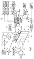
- a TDI sensor means A converts light received from a field of view into a corresponding electronic signal.
- a sweeping or rotating means B rotates or sweeps the field of view along all or part of a 360° panoramic circle.
- a timing and control processor C coordinates the shifting of rows of data in the TDI sensor means with its rotation such that an output video signal represents a sweeping field of view without blurring.
- a digital processing and memory means D stores, processes, and displays all or a portion of the panoramic image.
- a lens assembly 10 focuses light from a field of view 12 onto an image sensor 14.
- the image sensor 14 includes a plurality of CCD or other light sensitive elements arranged in a rectangular array.
- the light sensitive array includes a standard RS-170 CCD array which has 244 lines or rows of light sensitive elements and 600 elements per line. For higher resolution, larger CCD sensor arrays are preferred. More specifically, the rows or lines are oriented vertically, parallel to an axis of rotation of the field of view. Because the array is rectangular, the elements within each line can be visualized as horizontal columns parallel to a plane within which the field of view is swept.
- the lens assembly 10 is preferably adjustable, such as a zoom lens.
- the field of view 12 is selectively widened or narrowed.
- the lens might focus light or images from a 1° field of view on the sensor array 14 .
- the lens can "zoom in" on a smaller area 12' , e.g. a 0.1° field of view.
- the image sensor 14 is a color sensor. That is, the sensor has three CCD elements for each pixel. Prisms, filters, or the like render each element corresponding to the same pixel sensitive to only one of red, green, or blue light, for an RGB monitor. Other triadic color schemes may, of course, also he used.
- additional CCD elements may be provided corresponding to each pixel. The additional elements may have a phosphor, or the like which is responsive to other wavelengths of radiation, such as ultraviolet or infrared. In this manner, color, infrared, and UV images can he acquired concurrently.
- a vertical line of the available light e.g. a distant, stationary flagpole
- the vertical line or flagpole moves along the sensor array 14 .
- the charge on each element is dissipated in proportion to the amount of light received.
- the charge values are shifted line by line toward a shift register 22 .
- a control means 24 controls the shifting of the rows along the sensor array 14 .
- the control means 24 clocks the array 14 such that the line of charged values is shifted along the array 14 at the same speed that the vertical line of data or flagpole sweeps along the array 14 .
- the amount of charge dissipated by the image of the vertical line of light or flagpole continues over each of the lines of light sensitive elements.
- the image of the vertical line of light or the flagpole is integrated or summed 244 times.
- the shift register 22 serializes each line of charge values.
- a fast clock 26 clocks the shift register 22 600 times, or as many horizontal columns of array elements as may be present in the selected light sensitive array, in between each time the charge values are shifted by one vertical line. In this manner, the output of the shift register is a multiplicity of vertical lines of video data which taken together, represent a continuous image. There is no inherent frame end.
- a traditional interlaced video camera has an integration means which allows the light sensitive array to receive light for a preselected duration, e.g. 1/60th second.
- a control means performs 244 shift operations on lines of video data to shift the entire field as rapidly as possible into a CCD storage array or section 28 .
- the storage section is shielded from light.
- the light sensitive array of CCD elements 14 starts the collection of light for a second frame.
- a shift register serializes the 600 charge values of each of the 244 lines of video data into a video output signal.
- a traditional video camera produces a series of 244 lines x 600 pixels as a frame; whereas, the TDI sensor produces a continuous image.
- the control means 24 is also controllable to operate the TDI sensor A as a conventional video camera, particularly when there is no rotation. In this manner, detailed images of a region of interest can be made.
- the storage section When operating in the TDI mode, the storage section merely causes a 244 line delay before the lines reach the shift register.
- Suitable TDI imaging means for use in the present invention are found in U.S. Patent Nos. 5,040,057, 4,949,172, and 4,922,337.
- the output of the shift register 22 is conveyed to an amplifier 30 which amplifies the analog output of the shift register.
- a video processing channel 32 further processes the video signal with a bandpass filter for removing any vestiges of the clock signal noise, a gain amplifier, a clamping means for restoring DC video, and the like.
- a synchronization means 34 adds a "horizontal" blanking signal at the end of each vertical line of data. In the TDI mode, no frame or vertical retrace synchronization signals are needed. In this manner, an output video signal is generated on a continuum.
- each 360° rotation of the TDI imaging means produces an image which has (360°/rev.) x (244 lines/°) or about 88,000 vertical lines/revolution, each line having 600 pixel values. That is, a resultant 360° panoramic image with a 1° field of view would be an image with 88,000 x 600 pixel values.
- the sweeping means B includes a motor 40 operated by a motor controller/tachometer 42 to rotate the TDI imaging means A at a selectable rate.
- the motor controller 42 produces a clocking or tachometer signal at regular angular intervals, e.g. every 0.01° of angular rotation.
- a clocking means 44 adjusts the tachometer signals to produce clocking pulses which cause the control means 24 to clock the lines of charge along the light sensitive array 14 in coordination with the rotation. For example, if the field of view is 1°, then the clocking signal would cause each vertical line of charge values to be shifted every 1/244th° of rotation.
- a field of view indicating means 46 such as a resolver connected with zoom lens motor 16 , produces an output signal which indicates the field of view. If the field of view is reduced to 1/10th°, for example, the field of view means 46 causes a multiplying means 48 to multiply the clock signal by 10 . That is, instead of producing a clock signal with every 1/244th° of rotation, a clock signal is produced after each 1/2440th° of rotation. Similarly, when the field of view is enlarged, e.g. to 5°, the multiplying means 48 divides the clock signal such that the control means 24 is clocked after each 5/244th° of rotation.
- the amount of light integrated to make each pixel is dependent upon the rotational speed of the imaging means A .
- the rotational speed of the imaging means is adjusted to control the exposure. That is, the rotational speed is accelerated or slowed until a proper exposure is achieved. This enables the rate at which image data is acquired to be maximized for available lighting conditions. Alternately, it may be appropriate to slow the speed of rotation.
- An iris 50 is provided for selectively limiting the amount of light received by the light sensitive array 14 to optimize exposure.
- a set of slip rings 52 enable the video signal to he removed from the rotating TDI camera means A and enable the timing and control signals to be introduced into the imaging means A .
- the slip rings can carry the clocking signals and the signals from the shift register as in FIGURE 1.
- the analog video processing circuits and the clocking and control circuits can he mounted adjacent to the image sensor 14 for rotation therewith.
- the analog video output signals may he connected directly with a suitable display.
- the video signals are conveyed to digital video section 60 .
- the digital video section includes an analog-to-digital converter 62 , a memory loading means 64 for storing the digital data or pixel values in a panoramic image memory 66 .
- the memory loading means receives the tachometer signals to coordinate corresponding lines of data in subsequent revolutions.
- the panoramic image memory stores an 88,000 x 600 array of pixel values.
- Each of the pixel or data values has a gray scale of 8, 10, 12, or more bits.
- a digital video processor 68 converts the digital pixel values or data to a digital video signal.
- the digital video signal may be appropriately displayed on a digital video monitor as a sampled or scrolling image, or the like.
- a scan conversion facility in the image processor provides a video output signal compatible with conventional video monitors.
- a memory retrieval access means 70 selectively retrieves blocks of data from the panoramic memory 66 .
- the memory access means may retrieve a series of 480 x 600, or other appropriately sized blocks of pixels and supply each block to a scan converter means 72 .
- the scan converter generates an appropriate video signal for display on one or more video monitors.
- Various format video signals are contemplated including digital video, panoramic video, frame video, RS-170 video, and the like.
- An array of video monitors 74 may be grouped such that one of the video monitors shows the image to the east, another shows the image to the west, another to the northeast, etc. This enables a viewing room to be surrounded by video monitors which provide a substantially real time panoramic display of the surroundings.
- An appropriate indicator such as a vertical white line, may he provided to show the demarcation between the most recently received data and the data which was received almost a full revolution ago.
- a virtual reality means 76 may receive an appropriate block of pixel values from the memory 62 .
- the virtual reality means 76 includes means for indicating the direction which the viewer is facing and looking. These direction signals are used to control the memory retrieval means 70 to retrieve the blocks of pixel values representing the image in the direction the viewer is looking.
- One or more VCR's may be connected with the scan converter for recording the images.
- a plurality of image sensors 14 each receiving a different field of view, spectrum, or the like, each facing in a different direction, are counted to rotate together.
- two camera or image sensors mounted 180° apart enables the panoramic memory 66 to be updated twice as often.
- the timing and control signals may be such that the output lines are interlaced to improve resolution.
- one of the cameras may acquire odd-numbered vertical columns of the panoramic image and the other may acquire even-numbered vertical columns.
- the two cameras may be vertically offset to double the vertical field of view.
- the two cameras effective viewing position can be offset horizontally for stereoscopic imaging.
- an image intensifier may be disposed between the lens and the light sensitive element array 14 to increase light sensitivity.
- One of the image sensing means A includes a lens 90 which detects light to a mirror 92 and the zoom lens 10 .
- a prism means 94 separates the light into three color components focused on each of three respective light sensitive elements of the array 14 for each pixel. Shift registers serialize the data which is then supplied to the panoramic memory.
- a second image sensing means A' again has a zoom or other lens system 10 which focuses light on a phosphor 96 .
- the phosphor 96 converts light of a preselected wavelength into light of an optimal wavelength for the array of light sensing element array 14 .
- a sensor may be used in which a material sensitive to non-visible light is placed on a silicon sensor and provide signals directly to the sensor as a result of receiving the non-visible light.
- platinum silicide or pyroelectric materials may be used to sense infrared light.
- the phosphor 96 may be an ultraviolet conversion phosphor, or phosphors which convert energy of other wavelengths into appropriate optical light for the sensor array 14 .
- the motor 40 rotates a shaft which rotates the TDI imaging means A .
- the imaging means are mounted in a housing 100 which is mounted to a stationary structure 102 by one or more bearings 104 and a motor assembly 106.
- the tachometer 44 is mounted in conjunction with the motor 106 .
- all of the control signals can be generated within the housing 100 .
- the slip ring bearing arrangement 52 carries the output video signal, input controls for the zoom lens motor 16 , controls for the iris 50 , and for the motor 106 .
- Input control signals can also shift the control means 24 between the time delay and integration mode and a conventional video imaging mode.
- each image processing channel 32 and synchronization means 34 is conveyed to an analog-to-digital converter 110 .
- a multiplexing means 112 multiplexes the digital video signals.
- a demultiplexing or other sorting means 114 sorts the multiplexed digital values into an appropriate panoramic memory or memory portion.
- lens assembly 10 is illustrated as a zoom lens, other lenses are also contemplated.
- a lens or mirror 92 can be movable to shift the field of view.
- multiple lenses may be interchangeable, i.e. selectively moved into the optical path to change the optical properties.
- an anamorphic lens is used to alter the height to width ratio of the field of view. This alters the ratio of the coverage between the height of the image and the scan speed.
- the motor 40 can rotate the camera in either direction.
- the polarity of the clock signals changes. More precisely, a reverse direction signal is provided to the control means 24 such that the control means shifts the charge values in the opposite direction along the rows at the designated clock speed.
- a second shift register 110 is provided at the other end of the light sensitive array 14. Because only one of the shift registers 22 and 116 would be used at a time, their outputs use the same output circuitry.
- the shaft 100 is gimbaled or the like to compensate for tilt or rotational motion such as is found on an aircraft or other unstable platforms.
Description
A clocking means 44 adjusts the tachometer signals to produce clocking pulses which cause the control means 24 to clock the lines of charge along the light
Claims (16)
- A panoramic camera system comprising: a lens means (10) for focussing light from a field of view (12) onto an array of light sensitive elements (14); a sweeping means (B) for sweeping the field of view (12) about an axis of rotation, said sweeping means including a motor means (40) for rotating the lens (10) and the light sensitive element array (14) about the axis of rotation, the array of light sensitive elements (14) being defined by a plurality of lines of light sensitive elements, which element lines are oriented generally parallel to the axis of rotation; a time delay and integration control means (C) operatively connected to the sweeping means (B) for controlling the light sensitive array (14) such that lines of data are shifted along the array (14) in coordination with the rotation of the lens means (10) and the array (14) about the axis of rotation.
- A system according to claim 1, further including a tachometer means (42) for producing clocking signals in accordance with the rotation, the tachometer means (42) being connected with the time delay and integration control means (C) to supply clocking signals thereto.
- A system according to claim 2 further including: a field of view adjusting means (16) for selectively adjusting the field of view (12) of the lens means (10); a clocking signal adjusting means (44, 46, 48) operatively connected with the tachometer means (42) and the control means (C) for altering the clocking signals in accordance with changes in the field of view.
- A system according to anyone of claims 1 to 3 further including: a video processing circuit (32) for processing the lines of data from the light sensitive element array (14) into analog video signals; an analog-to-digital converter means (62) for converting the analog video signals into digital video signals; a digital memory means (66) for storing the digital video signals.
- A system according to claim 4 further including a memory updating means (64), the memory updating means (64) being connected with the tachometer means (42) and the analog-to-digital converter (62) for selectively updating the digital memory means (66) such that the digital memory means (66) holds a digital representation of a panoramic view which is updated with each resweep of a common panoramic region.
- A system according to claim 5 further including an image processor means (72) operatively connected with the memory means (66) for converting portions of the panoramic image representation stored therein into man-readable displays.
- A system according to claim 4 further including a vertical scan video monitor operatively connected with the video processing circuit (32) for converting the video signal into a man-readable display.
- A system according to claim 1 further including: a second lens means (10) for focusing light from a second field of view on a second light sensitive element array (14); a second time delay and integration control means (24) for controlling the second light sensitive element array (14) such that lines of data are shifted along the light sensitive element array (14) in coordination with the sweeping about the axis of rotation.
- A system according to claim 8 further including video processing means (32) for converting the lines of data from the first and second light sensitive element arrays (14) into analog video signals.
- A system according to claim 9 further including a spectrum means (96) disposed between the second lens means (10) and the second light sensitive element array (14) for converting light of a preselected spectrum into light of a wavelength to which the second light sensitive element array (14) is sensitive.
- A system according to claim 10 wherein the spectrum means (96) includes a platinum silicide coating for converting infrared light to an electrical signal to which the underlying array (14) is receptive.
- A system according to claim 9 or claim 10 or claim 11 further including an analog to digital converter means (110) for converting the analog video signals to digital video signals.
- A system according to claim 12 further including a multiplexing means (112) for multiplexing the digital video signals.
- A system according to claim 12 further including a panoramic memory means (66) and a panoramic memory loading means (64) for loading digital video signal data from the digital video signals into the panoramic video memory means (66), the memory loading means (64) correlating data from corresponding spatial regions of the first and second fields of view into a composite image.
- A system according to claim 12 further including first and second panoramic memory means and a memory loading means for loading the first panoramic memory means with digital video data from the first light sensitive element array (14) and for loading the second panoramic memory means with digital video data from the second light sensitive memory array (14).
- A system according to claim 15 further including a digital video processing means for selectively reading digital video information from the first and second panoramic memory means and generating a man-readable display of at least a portion of the data therefrom.
Applications Claiming Priority (2)
| Application Number | Priority Date | Filing Date | Title |
|---|---|---|---|
| US97963392A | 1992-11-20 | 1992-11-20 | |
| US979633 | 1992-11-20 |
Publications (2)
| Publication Number | Publication Date |
|---|---|
| EP0599470A1 EP0599470A1 (en) | 1994-06-01 |
| EP0599470B1 true EP0599470B1 (en) | 1998-09-16 |
Family
ID=25527028
Family Applications (1)
| Application Number | Title | Priority Date | Filing Date |
|---|---|---|---|
| EP93307990A Expired - Lifetime EP0599470B1 (en) | 1992-11-20 | 1993-10-07 | Panoramic camera systems |
Country Status (4)
| Country | Link |
|---|---|
| EP (1) | EP0599470B1 (en) |
| JP (1) | JPH06222481A (en) |
| DE (1) | DE69321078T2 (en) |
| FI (1) | FI935145A (en) |
Families Citing this family (21)
| Publication number | Priority date | Publication date | Assignee | Title |
|---|---|---|---|---|
| DE4443821A1 (en) * | 1994-12-09 | 1996-06-20 | Telefunken Microelectron | Picture-taking device without CCD's |
| GB2298100A (en) * | 1995-02-07 | 1996-08-21 | Peng Seng Toh | High resolution video imaging system for simultaneous acquisition of two high aspect ratio object fields |
| JPH114398A (en) * | 1997-06-11 | 1999-01-06 | Hitachi Ltd | Digital wide camera |
| DE19847403B4 (en) * | 1997-10-22 | 2004-09-02 | Püllen, Rainer | Image recording system (interactive room image acquisition) |
| US6304284B1 (en) * | 1998-03-31 | 2001-10-16 | Intel Corporation | Method of and apparatus for creating panoramic or surround images using a motion sensor equipped camera |
| DE19834597A1 (en) | 1998-07-31 | 2000-02-10 | Gerhard Bonnet | Device and method for color recording an image |
| DE10332275B4 (en) * | 2003-07-10 | 2005-05-04 | Deutsches Zentrum für Luft- und Raumfahrt e.V. | Panoramic image projector |
| US8124929B2 (en) | 2004-08-25 | 2012-02-28 | Protarius Filo Ag, L.L.C. | Imager module optical focus and assembly method |
| US7795577B2 (en) | 2004-08-25 | 2010-09-14 | Richard Ian Olsen | Lens frame and optical focus assembly for imager module |
| US7564019B2 (en) | 2005-08-25 | 2009-07-21 | Richard Ian Olsen | Large dynamic range cameras |
| US7916180B2 (en) | 2004-08-25 | 2011-03-29 | Protarius Filo Ag, L.L.C. | Simultaneous multiple field of view digital cameras |
| EP1812968B1 (en) | 2004-08-25 | 2019-01-16 | Callahan Cellular L.L.C. | Apparatus for multiple camera devices and method of operating same |
| US20070102622A1 (en) | 2005-07-01 | 2007-05-10 | Olsen Richard I | Apparatus for multiple camera devices and method of operating same |
| US7566855B2 (en) | 2005-08-25 | 2009-07-28 | Richard Ian Olsen | Digital camera with integrated infrared (IR) response |
| US7964835B2 (en) | 2005-08-25 | 2011-06-21 | Protarius Filo Ag, L.L.C. | Digital cameras with direct luminance and chrominance detection |
| KR100925399B1 (en) * | 2009-02-23 | 2009-11-09 | (주) 반도전기통신 | The superpanorama digital video recording system with multi-channel |
| JP2018005080A (en) * | 2016-07-06 | 2018-01-11 | 株式会社ニコン | Imaging device |
| CN107835959B (en) * | 2015-07-10 | 2021-04-09 | 株式会社尼康 | Imaging device, imaging optical system, method for manufacturing imaging device, and imaging method |
| DE102016110686A1 (en) * | 2016-06-10 | 2017-12-14 | Rheinmetall Defence Electronics Gmbh | Method and device for creating a panoramic image |
| KR20180054358A (en) * | 2016-11-15 | 2018-05-24 | 김정훈 | Low speed rotating camera |
| IT202100014987A1 (en) * | 2021-06-09 | 2022-12-09 | M E S S P A | Periscope opto-electronic system |
Family Cites Families (2)
| Publication number | Priority date | Publication date | Assignee | Title |
|---|---|---|---|---|
| US5040057A (en) * | 1990-08-13 | 1991-08-13 | Picker International, Inc. | Multi-mode TDI/raster-scan television camera system |
| JP2651872B2 (en) * | 1989-09-28 | 1997-09-10 | 松下電器産業株式会社 | CCTV system equipment |
-
1993
- 1993-10-07 DE DE69321078T patent/DE69321078T2/en not_active Expired - Fee Related
- 1993-10-07 EP EP93307990A patent/EP0599470B1/en not_active Expired - Lifetime
- 1993-11-04 JP JP5297561A patent/JPH06222481A/en active Pending
- 1993-11-19 FI FI935145A patent/FI935145A/en unknown
Also Published As
| Publication number | Publication date |
|---|---|
| FI935145A (en) | 1994-05-21 |
| DE69321078D1 (en) | 1998-10-22 |
| EP0599470A1 (en) | 1994-06-01 |
| DE69321078T2 (en) | 1999-02-25 |
| FI935145A0 (en) | 1993-11-19 |
| JPH06222481A (en) | 1994-08-12 |
Similar Documents
| Publication | Publication Date | Title |
|---|---|---|
| US5650813A (en) | Panoramic time delay and integration video camera system | |
| EP0599470B1 (en) | Panoramic camera systems | |
| US6005617A (en) | Electronic camera with mechanical subscanner | |
| US5721585A (en) | Digital video panoramic image capture and display system | |
| US5060074A (en) | Video imaging apparatus | |
| CA1284375C (en) | Electronic mosaic imaging process | |
| US5159455A (en) | Multisensor high-resolution camera | |
| JP2753541B2 (en) | Still image pickup device | |
| JPH03502755A (en) | Photoelectric color image sensor | |
| JPH05225318A (en) | Image system having wide field of view | |
| JPH03500119A (en) | Low resolution confirmation device for still video images | |
| EP0947091A1 (en) | System and method for image motion compensation of a ccd image sensor | |
| EP0120911A1 (en) | Film video player. | |
| US6646680B1 (en) | Focusing method and apparatus for high resolution digital cameras | |
| Lareau | Electro-optical imaging array with motion compensation | |
| US3113180A (en) | Composite image reproducing means | |
| US5321798A (en) | Apparatus for providing a composite digital representation of a scene within a field-of-regard | |
| US4660098A (en) | Apparatus for producing copies of a video image utilizing line pattern rotation | |
| JPH06292052A (en) | Still picture image pickup device | |
| EP1313308B1 (en) | Electro-optical reconnaissance system with forward motion compensation | |
| JP2000078467A (en) | Picture compositing method | |
| EP0512826B1 (en) | Video signal recording apparatus | |
| KR20010046654A (en) | Single camera multiple scene observing device | |
| US4994919A (en) | Camera for recording television, photographic or cinematographic images, including an automatic focus-setting device | |
| MacDonald et al. | An ultra-high resolution digital camera |
Legal Events
| Date | Code | Title | Description |
|---|---|---|---|
| PUAI | Public reference made under article 153(3) epc to a published international application that has entered the european phase |
Free format text: ORIGINAL CODE: 0009012 |
|
| AK | Designated contracting states |
Kind code of ref document: A1 Designated state(s): DE DK FR GB NL SE |
|
| 17P | Request for examination filed |
Effective date: 19941122 |
|
| 17Q | First examination report despatched |
Effective date: 19970225 |
|
| GRAG | Despatch of communication of intention to grant |
Free format text: ORIGINAL CODE: EPIDOS AGRA |
|
| GRAG | Despatch of communication of intention to grant |
Free format text: ORIGINAL CODE: EPIDOS AGRA |
|
| GRAH | Despatch of communication of intention to grant a patent |
Free format text: ORIGINAL CODE: EPIDOS IGRA |
|
| GRAH | Despatch of communication of intention to grant a patent |
Free format text: ORIGINAL CODE: EPIDOS IGRA |
|
| GRAA | (expected) grant |
Free format text: ORIGINAL CODE: 0009210 |
|
| AK | Designated contracting states |
Kind code of ref document: B1 Designated state(s): DE DK FR GB NL SE |
|
| REF | Corresponds to: |
Ref document number: 69321078 Country of ref document: DE Date of ref document: 19981022 |
|
| ET | Fr: translation filed | ||
| PG25 | Lapsed in a contracting state [announced via postgrant information from national office to epo] |
Ref country code: SE Free format text: LAPSE BECAUSE OF FAILURE TO SUBMIT A TRANSLATION OF THE DESCRIPTION OR TO PAY THE FEE WITHIN THE PRESCRIBED TIME-LIMIT Effective date: 19981216 Ref country code: DK Free format text: LAPSE BECAUSE OF FAILURE TO SUBMIT A TRANSLATION OF THE DESCRIPTION OR TO PAY THE FEE WITHIN THE PRESCRIBED TIME-LIMIT Effective date: 19981216 |
|
| PLBE | No opposition filed within time limit |
Free format text: ORIGINAL CODE: 0009261 |
|
| STAA | Information on the status of an ep patent application or granted ep patent |
Free format text: STATUS: NO OPPOSITION FILED WITHIN TIME LIMIT |
|
| 26N | No opposition filed | ||
| REG | Reference to a national code |
Ref country code: GB Ref legal event code: IF02 |
|
| PGFP | Annual fee paid to national office [announced via postgrant information from national office to epo] |
Ref country code: GB Payment date: 20020913 Year of fee payment: 10 |
|
| PGFP | Annual fee paid to national office [announced via postgrant information from national office to epo] |
Ref country code: NL Payment date: 20020919 Year of fee payment: 10 |
|
| PGFP | Annual fee paid to national office [announced via postgrant information from national office to epo] |
Ref country code: FR Payment date: 20021003 Year of fee payment: 10 |
|
| PGFP | Annual fee paid to national office [announced via postgrant information from national office to epo] |
Ref country code: DE Payment date: 20021031 Year of fee payment: 10 |
|
| PG25 | Lapsed in a contracting state [announced via postgrant information from national office to epo] |
Ref country code: GB Free format text: LAPSE BECAUSE OF NON-PAYMENT OF DUE FEES Effective date: 20031007 |
|
| PG25 | Lapsed in a contracting state [announced via postgrant information from national office to epo] |
Ref country code: NL Free format text: LAPSE BECAUSE OF NON-PAYMENT OF DUE FEES Effective date: 20040501 Ref country code: DE Free format text: LAPSE BECAUSE OF NON-PAYMENT OF DUE FEES Effective date: 20040501 |
|
| GBPC | Gb: european patent ceased through non-payment of renewal fee |
Effective date: 20031007 |
|
| PG25 | Lapsed in a contracting state [announced via postgrant information from national office to epo] |
Ref country code: FR Free format text: LAPSE BECAUSE OF NON-PAYMENT OF DUE FEES Effective date: 20040630 |
|
| NLV4 | Nl: lapsed or anulled due to non-payment of the annual fee |
Effective date: 20040501 |
|
| REG | Reference to a national code |
Ref country code: FR Ref legal event code: ST |