EP0599057B1 - Total containment device for connect/disconnect of plastic tubes - Google Patents
Total containment device for connect/disconnect of plastic tubes Download PDFInfo
- Publication number
- EP0599057B1 EP0599057B1 EP93116980A EP93116980A EP0599057B1 EP 0599057 B1 EP0599057 B1 EP 0599057B1 EP 93116980 A EP93116980 A EP 93116980A EP 93116980 A EP93116980 A EP 93116980A EP 0599057 B1 EP0599057 B1 EP 0599057B1
- Authority
- EP
- European Patent Office
- Prior art keywords
- clamp
- wafer
- welder
- tubes
- tube
- Prior art date
- Legal status (The legal status is an assumption and is not a legal conclusion. Google has not performed a legal analysis and makes no representation as to the accuracy of the status listed.)
- Expired - Lifetime
Links
- 239000004033 plastic Substances 0.000 title claims abstract description 16
- 238000000034 method Methods 0.000 claims description 35
- 230000007246 mechanism Effects 0.000 claims description 30
- 239000000443 aerosol Substances 0.000 claims description 12
- 238000010791 quenching Methods 0.000 claims description 7
- 238000003825 pressing Methods 0.000 claims description 5
- RYGMFSIKBFXOCR-UHFFFAOYSA-N Copper Chemical compound [Cu] RYGMFSIKBFXOCR-UHFFFAOYSA-N 0.000 claims description 4
- 238000004891 communication Methods 0.000 claims description 4
- 229910052802 copper Inorganic materials 0.000 claims description 4
- 239000010949 copper Substances 0.000 claims description 4
- 238000010438 heat treatment Methods 0.000 claims description 3
- 238000005520 cutting process Methods 0.000 description 6
- 238000010586 diagram Methods 0.000 description 4
- 239000000155 melt Substances 0.000 description 4
- 230000000712 assembly Effects 0.000 description 3
- 238000000429 assembly Methods 0.000 description 3
- 238000001816 cooling Methods 0.000 description 3
- 230000006870 function Effects 0.000 description 3
- 230000008569 process Effects 0.000 description 3
- 239000007787 solid Substances 0.000 description 3
- 229920005992 thermoplastic resin Polymers 0.000 description 3
- 238000003466 welding Methods 0.000 description 3
- 239000007789 gas Substances 0.000 description 2
- 230000003287 optical effect Effects 0.000 description 2
- 238000012360 testing method Methods 0.000 description 2
- 238000011144 upstream manufacturing Methods 0.000 description 2
- WQZGKKKJIJFFOK-GASJEMHNSA-N Glucose Chemical compound OC[C@H]1OC(O)[C@H](O)[C@@H](O)[C@@H]1O WQZGKKKJIJFFOK-GASJEMHNSA-N 0.000 description 1
- 230000009471 action Effects 0.000 description 1
- 238000013459 approach Methods 0.000 description 1
- 239000008280 blood Substances 0.000 description 1
- 210000004369 blood Anatomy 0.000 description 1
- 239000003990 capacitor Substances 0.000 description 1
- 238000004590 computer program Methods 0.000 description 1
- 230000001143 conditioned effect Effects 0.000 description 1
- 239000000356 contaminant Substances 0.000 description 1
- 238000005516 engineering process Methods 0.000 description 1
- 239000012530 fluid Substances 0.000 description 1
- 230000000415 inactivating effect Effects 0.000 description 1
- 238000005304 joining Methods 0.000 description 1
- 239000000463 material Substances 0.000 description 1
- 238000002844 melting Methods 0.000 description 1
- 230000008018 melting Effects 0.000 description 1
- 238000003032 molecular docking Methods 0.000 description 1
- 238000012544 monitoring process Methods 0.000 description 1
- 210000004303 peritoneum Anatomy 0.000 description 1
- 238000004023 plastic welding Methods 0.000 description 1
- 238000012545 processing Methods 0.000 description 1
- 230000000171 quenching effect Effects 0.000 description 1
- 230000004044 response Effects 0.000 description 1
- 230000002441 reversible effect Effects 0.000 description 1
- 238000000518 rheometry Methods 0.000 description 1
- 239000000779 smoke Substances 0.000 description 1
Images




Classifications
-
- B—PERFORMING OPERATIONS; TRANSPORTING
- B29—WORKING OF PLASTICS; WORKING OF SUBSTANCES IN A PLASTIC STATE IN GENERAL
- B29C—SHAPING OR JOINING OF PLASTICS; SHAPING OF MATERIAL IN A PLASTIC STATE, NOT OTHERWISE PROVIDED FOR; AFTER-TREATMENT OF THE SHAPED PRODUCTS, e.g. REPAIRING
- B29C65/00—Joining or sealing of preformed parts, e.g. welding of plastics materials; Apparatus therefor
- B29C65/78—Means for handling the parts to be joined, e.g. for making containers or hollow articles, e.g. means for handling sheets, plates, web-like materials, tubular articles, hollow articles or elements to be joined therewith; Means for discharging the joined articles from the joining apparatus
- B29C65/7802—Positioning the parts to be joined, e.g. aligning, indexing or centring
-
- B—PERFORMING OPERATIONS; TRANSPORTING
- B29—WORKING OF PLASTICS; WORKING OF SUBSTANCES IN A PLASTIC STATE IN GENERAL
- B29C—SHAPING OR JOINING OF PLASTICS; SHAPING OF MATERIAL IN A PLASTIC STATE, NOT OTHERWISE PROVIDED FOR; AFTER-TREATMENT OF THE SHAPED PRODUCTS, e.g. REPAIRING
- B29C57/00—Shaping of tube ends, e.g. flanging, belling or closing; Apparatus therefor, e.g. collapsible mandrels
- B29C57/10—Closing
-
- B—PERFORMING OPERATIONS; TRANSPORTING
- B29—WORKING OF PLASTICS; WORKING OF SUBSTANCES IN A PLASTIC STATE IN GENERAL
- B29C—SHAPING OR JOINING OF PLASTICS; SHAPING OF MATERIAL IN A PLASTIC STATE, NOT OTHERWISE PROVIDED FOR; AFTER-TREATMENT OF THE SHAPED PRODUCTS, e.g. REPAIRING
- B29C65/00—Joining or sealing of preformed parts, e.g. welding of plastics materials; Apparatus therefor
- B29C65/02—Joining or sealing of preformed parts, e.g. welding of plastics materials; Apparatus therefor by heating, with or without pressure
- B29C65/18—Joining or sealing of preformed parts, e.g. welding of plastics materials; Apparatus therefor by heating, with or without pressure using heated tools
- B29C65/20—Joining or sealing of preformed parts, e.g. welding of plastics materials; Apparatus therefor by heating, with or without pressure using heated tools with direct contact, e.g. using "mirror"
- B29C65/2046—Joining or sealing of preformed parts, e.g. welding of plastics materials; Apparatus therefor by heating, with or without pressure using heated tools with direct contact, e.g. using "mirror" using a welding mirror which also cuts the parts to be joined, e.g. for sterile welding
-
- B—PERFORMING OPERATIONS; TRANSPORTING
- B29—WORKING OF PLASTICS; WORKING OF SUBSTANCES IN A PLASTIC STATE IN GENERAL
- B29C—SHAPING OR JOINING OF PLASTICS; SHAPING OF MATERIAL IN A PLASTIC STATE, NOT OTHERWISE PROVIDED FOR; AFTER-TREATMENT OF THE SHAPED PRODUCTS, e.g. REPAIRING
- B29C66/00—General aspects of processes or apparatus for joining preformed parts
- B29C66/001—Joining in special atmospheres
- B29C66/0012—Joining in special atmospheres characterised by the type of environment
- B29C66/0018—Joining in special atmospheres characterised by the type of environment being sterile
-
- B—PERFORMING OPERATIONS; TRANSPORTING
- B29—WORKING OF PLASTICS; WORKING OF SUBSTANCES IN A PLASTIC STATE IN GENERAL
- B29C—SHAPING OR JOINING OF PLASTICS; SHAPING OF MATERIAL IN A PLASTIC STATE, NOT OTHERWISE PROVIDED FOR; AFTER-TREATMENT OF THE SHAPED PRODUCTS, e.g. REPAIRING
- B29C66/00—General aspects of processes or apparatus for joining preformed parts
- B29C66/002—Removing toxic gases
-
- B—PERFORMING OPERATIONS; TRANSPORTING
- B29—WORKING OF PLASTICS; WORKING OF SUBSTANCES IN A PLASTIC STATE IN GENERAL
- B29C—SHAPING OR JOINING OF PLASTICS; SHAPING OF MATERIAL IN A PLASTIC STATE, NOT OTHERWISE PROVIDED FOR; AFTER-TREATMENT OF THE SHAPED PRODUCTS, e.g. REPAIRING
- B29C66/00—General aspects of processes or apparatus for joining preformed parts
- B29C66/01—General aspects dealing with the joint area or with the area to be joined
- B29C66/03—After-treatments in the joint area
- B29C66/032—Mechanical after-treatments
-
- B—PERFORMING OPERATIONS; TRANSPORTING
- B29—WORKING OF PLASTICS; WORKING OF SUBSTANCES IN A PLASTIC STATE IN GENERAL
- B29C—SHAPING OR JOINING OF PLASTICS; SHAPING OF MATERIAL IN A PLASTIC STATE, NOT OTHERWISE PROVIDED FOR; AFTER-TREATMENT OF THE SHAPED PRODUCTS, e.g. REPAIRING
- B29C66/00—General aspects of processes or apparatus for joining preformed parts
- B29C66/01—General aspects dealing with the joint area or with the area to be joined
- B29C66/03—After-treatments in the joint area
- B29C66/032—Mechanical after-treatments
- B29C66/0324—Reforming or reshaping the joint, e.g. folding over
-
- B—PERFORMING OPERATIONS; TRANSPORTING
- B29—WORKING OF PLASTICS; WORKING OF SUBSTANCES IN A PLASTIC STATE IN GENERAL
- B29C—SHAPING OR JOINING OF PLASTICS; SHAPING OF MATERIAL IN A PLASTIC STATE, NOT OTHERWISE PROVIDED FOR; AFTER-TREATMENT OF THE SHAPED PRODUCTS, e.g. REPAIRING
- B29C66/00—General aspects of processes or apparatus for joining preformed parts
- B29C66/01—General aspects dealing with the joint area or with the area to be joined
- B29C66/05—Particular design of joint configurations
- B29C66/10—Particular design of joint configurations particular design of the joint cross-sections
- B29C66/11—Joint cross-sections comprising a single joint-segment, i.e. one of the parts to be joined comprising a single joint-segment in the joint cross-section
- B29C66/112—Single lapped joints
- B29C66/1122—Single lap to lap joints, i.e. overlap joints
-
- B—PERFORMING OPERATIONS; TRANSPORTING
- B29—WORKING OF PLASTICS; WORKING OF SUBSTANCES IN A PLASTIC STATE IN GENERAL
- B29C—SHAPING OR JOINING OF PLASTICS; SHAPING OF MATERIAL IN A PLASTIC STATE, NOT OTHERWISE PROVIDED FOR; AFTER-TREATMENT OF THE SHAPED PRODUCTS, e.g. REPAIRING
- B29C66/00—General aspects of processes or apparatus for joining preformed parts
- B29C66/01—General aspects dealing with the joint area or with the area to be joined
- B29C66/05—Particular design of joint configurations
- B29C66/10—Particular design of joint configurations particular design of the joint cross-sections
- B29C66/11—Joint cross-sections comprising a single joint-segment, i.e. one of the parts to be joined comprising a single joint-segment in the joint cross-section
- B29C66/114—Single butt joints
- B29C66/1142—Single butt to butt joints
-
- B—PERFORMING OPERATIONS; TRANSPORTING
- B29—WORKING OF PLASTICS; WORKING OF SUBSTANCES IN A PLASTIC STATE IN GENERAL
- B29C—SHAPING OR JOINING OF PLASTICS; SHAPING OF MATERIAL IN A PLASTIC STATE, NOT OTHERWISE PROVIDED FOR; AFTER-TREATMENT OF THE SHAPED PRODUCTS, e.g. REPAIRING
- B29C66/00—General aspects of processes or apparatus for joining preformed parts
- B29C66/01—General aspects dealing with the joint area or with the area to be joined
- B29C66/05—Particular design of joint configurations
- B29C66/10—Particular design of joint configurations particular design of the joint cross-sections
- B29C66/13—Single flanged joints; Fin-type joints; Single hem joints; Edge joints; Interpenetrating fingered joints; Other specific particular designs of joint cross-sections not provided for in groups B29C66/11 - B29C66/12
- B29C66/133—Fin-type joints, the parts to be joined being flexible
-
- B—PERFORMING OPERATIONS; TRANSPORTING
- B29—WORKING OF PLASTICS; WORKING OF SUBSTANCES IN A PLASTIC STATE IN GENERAL
- B29C—SHAPING OR JOINING OF PLASTICS; SHAPING OF MATERIAL IN A PLASTIC STATE, NOT OTHERWISE PROVIDED FOR; AFTER-TREATMENT OF THE SHAPED PRODUCTS, e.g. REPAIRING
- B29C66/00—General aspects of processes or apparatus for joining preformed parts
- B29C66/01—General aspects dealing with the joint area or with the area to be joined
- B29C66/32—Measures for keeping the burr form under control; Avoiding burr formation; Shaping the burr
- B29C66/326—Shaping the burr, e.g. by the joining tool
-
- B—PERFORMING OPERATIONS; TRANSPORTING
- B29—WORKING OF PLASTICS; WORKING OF SUBSTANCES IN A PLASTIC STATE IN GENERAL
- B29C—SHAPING OR JOINING OF PLASTICS; SHAPING OF MATERIAL IN A PLASTIC STATE, NOT OTHERWISE PROVIDED FOR; AFTER-TREATMENT OF THE SHAPED PRODUCTS, e.g. REPAIRING
- B29C66/00—General aspects of processes or apparatus for joining preformed parts
- B29C66/01—General aspects dealing with the joint area or with the area to be joined
- B29C66/32—Measures for keeping the burr form under control; Avoiding burr formation; Shaping the burr
- B29C66/328—Leaving the burrs unchanged for providing particular properties to the joint, e.g. as decorative effect
- B29C66/3282—Leaving the burrs unchanged for providing particular properties to the joint, e.g. as decorative effect for reinforcing the joint
-
- B—PERFORMING OPERATIONS; TRANSPORTING
- B29—WORKING OF PLASTICS; WORKING OF SUBSTANCES IN A PLASTIC STATE IN GENERAL
- B29C—SHAPING OR JOINING OF PLASTICS; SHAPING OF MATERIAL IN A PLASTIC STATE, NOT OTHERWISE PROVIDED FOR; AFTER-TREATMENT OF THE SHAPED PRODUCTS, e.g. REPAIRING
- B29C66/00—General aspects of processes or apparatus for joining preformed parts
- B29C66/40—General aspects of joining substantially flat articles, e.g. plates, sheets or web-like materials; Making flat seams in tubular or hollow articles; Joining single elements to substantially flat surfaces
- B29C66/41—Joining substantially flat articles ; Making flat seams in tubular or hollow articles
- B29C66/43—Joining a relatively small portion of the surface of said articles
-
- B—PERFORMING OPERATIONS; TRANSPORTING
- B29—WORKING OF PLASTICS; WORKING OF SUBSTANCES IN A PLASTIC STATE IN GENERAL
- B29C—SHAPING OR JOINING OF PLASTICS; SHAPING OF MATERIAL IN A PLASTIC STATE, NOT OTHERWISE PROVIDED FOR; AFTER-TREATMENT OF THE SHAPED PRODUCTS, e.g. REPAIRING
- B29C66/00—General aspects of processes or apparatus for joining preformed parts
- B29C66/50—General aspects of joining tubular articles; General aspects of joining long products, i.e. bars or profiled elements; General aspects of joining single elements to tubular articles, hollow articles or bars; General aspects of joining several hollow-preforms to form hollow or tubular articles
- B29C66/51—Joining tubular articles, profiled elements or bars; Joining single elements to tubular articles, hollow articles or bars; Joining several hollow-preforms to form hollow or tubular articles
- B29C66/52—Joining tubular articles, bars or profiled elements
- B29C66/522—Joining tubular articles
- B29C66/5221—Joining tubular articles for forming coaxial connections, i.e. the tubular articles to be joined forming a zero angle relative to each other
-
- B—PERFORMING OPERATIONS; TRANSPORTING
- B29—WORKING OF PLASTICS; WORKING OF SUBSTANCES IN A PLASTIC STATE IN GENERAL
- B29C—SHAPING OR JOINING OF PLASTICS; SHAPING OF MATERIAL IN A PLASTIC STATE, NOT OTHERWISE PROVIDED FOR; AFTER-TREATMENT OF THE SHAPED PRODUCTS, e.g. REPAIRING
- B29C66/00—General aspects of processes or apparatus for joining preformed parts
- B29C66/70—General aspects of processes or apparatus for joining preformed parts characterised by the composition, physical properties or the structure of the material of the parts to be joined; Joining with non-plastics material
- B29C66/73—General aspects of processes or apparatus for joining preformed parts characterised by the composition, physical properties or the structure of the material of the parts to be joined; Joining with non-plastics material characterised by the intensive physical properties of the material of the parts to be joined, by the optical properties of the material of the parts to be joined, by the extensive physical properties of the parts to be joined, by the state of the material of the parts to be joined or by the material of the parts to be joined being a thermoplastic or a thermoset
- B29C66/739—General aspects of processes or apparatus for joining preformed parts characterised by the composition, physical properties or the structure of the material of the parts to be joined; Joining with non-plastics material characterised by the intensive physical properties of the material of the parts to be joined, by the optical properties of the material of the parts to be joined, by the extensive physical properties of the parts to be joined, by the state of the material of the parts to be joined or by the material of the parts to be joined being a thermoplastic or a thermoset characterised by the material of the parts to be joined being a thermoplastic or a thermoset
- B29C66/7392—General aspects of processes or apparatus for joining preformed parts characterised by the composition, physical properties or the structure of the material of the parts to be joined; Joining with non-plastics material characterised by the intensive physical properties of the material of the parts to be joined, by the optical properties of the material of the parts to be joined, by the extensive physical properties of the parts to be joined, by the state of the material of the parts to be joined or by the material of the parts to be joined being a thermoplastic or a thermoset characterised by the material of the parts to be joined being a thermoplastic or a thermoset characterised by the material of at least one of the parts being a thermoplastic
- B29C66/73921—General aspects of processes or apparatus for joining preformed parts characterised by the composition, physical properties or the structure of the material of the parts to be joined; Joining with non-plastics material characterised by the intensive physical properties of the material of the parts to be joined, by the optical properties of the material of the parts to be joined, by the extensive physical properties of the parts to be joined, by the state of the material of the parts to be joined or by the material of the parts to be joined being a thermoplastic or a thermoset characterised by the material of the parts to be joined being a thermoplastic or a thermoset characterised by the material of at least one of the parts being a thermoplastic characterised by the materials of both parts being thermoplastics
-
- B—PERFORMING OPERATIONS; TRANSPORTING
- B29—WORKING OF PLASTICS; WORKING OF SUBSTANCES IN A PLASTIC STATE IN GENERAL
- B29C—SHAPING OR JOINING OF PLASTICS; SHAPING OF MATERIAL IN A PLASTIC STATE, NOT OTHERWISE PROVIDED FOR; AFTER-TREATMENT OF THE SHAPED PRODUCTS, e.g. REPAIRING
- B29C66/00—General aspects of processes or apparatus for joining preformed parts
- B29C66/80—General aspects of machine operations or constructions and parts thereof
-
- B—PERFORMING OPERATIONS; TRANSPORTING
- B29—WORKING OF PLASTICS; WORKING OF SUBSTANCES IN A PLASTIC STATE IN GENERAL
- B29C—SHAPING OR JOINING OF PLASTICS; SHAPING OF MATERIAL IN A PLASTIC STATE, NOT OTHERWISE PROVIDED FOR; AFTER-TREATMENT OF THE SHAPED PRODUCTS, e.g. REPAIRING
- B29C66/00—General aspects of processes or apparatus for joining preformed parts
- B29C66/80—General aspects of machine operations or constructions and parts thereof
- B29C66/81—General aspects of the pressing elements, i.e. the elements applying pressure on the parts to be joined in the area to be joined, e.g. the welding jaws or clamps
- B29C66/816—General aspects of the pressing elements, i.e. the elements applying pressure on the parts to be joined in the area to be joined, e.g. the welding jaws or clamps characterised by the mounting of the pressing elements, e.g. of the welding jaws or clamps
- B29C66/8167—Quick change joining tools or surfaces
-
- B—PERFORMING OPERATIONS; TRANSPORTING
- B29—WORKING OF PLASTICS; WORKING OF SUBSTANCES IN A PLASTIC STATE IN GENERAL
- B29C—SHAPING OR JOINING OF PLASTICS; SHAPING OF MATERIAL IN A PLASTIC STATE, NOT OTHERWISE PROVIDED FOR; AFTER-TREATMENT OF THE SHAPED PRODUCTS, e.g. REPAIRING
- B29C66/00—General aspects of processes or apparatus for joining preformed parts
- B29C66/80—General aspects of machine operations or constructions and parts thereof
- B29C66/84—Specific machine types or machines suitable for specific applications
- B29C66/857—Medical tube welding machines
-
- B—PERFORMING OPERATIONS; TRANSPORTING
- B29—WORKING OF PLASTICS; WORKING OF SUBSTANCES IN A PLASTIC STATE IN GENERAL
- B29C—SHAPING OR JOINING OF PLASTICS; SHAPING OF MATERIAL IN A PLASTIC STATE, NOT OTHERWISE PROVIDED FOR; AFTER-TREATMENT OF THE SHAPED PRODUCTS, e.g. REPAIRING
- B29C66/00—General aspects of processes or apparatus for joining preformed parts
- B29C66/80—General aspects of machine operations or constructions and parts thereof
- B29C66/84—Specific machine types or machines suitable for specific applications
- B29C66/861—Hand-held tools
- B29C66/8618—Hand-held tools being battery operated
-
- B—PERFORMING OPERATIONS; TRANSPORTING
- B29—WORKING OF PLASTICS; WORKING OF SUBSTANCES IN A PLASTIC STATE IN GENERAL
- B29C—SHAPING OR JOINING OF PLASTICS; SHAPING OF MATERIAL IN A PLASTIC STATE, NOT OTHERWISE PROVIDED FOR; AFTER-TREATMENT OF THE SHAPED PRODUCTS, e.g. REPAIRING
- B29C66/00—General aspects of processes or apparatus for joining preformed parts
- B29C66/80—General aspects of machine operations or constructions and parts thereof
- B29C66/87—Auxiliary operations or devices
- B29C66/876—Maintenance or cleaning
- B29C66/8762—Cleaning of the joining tools
-
- B—PERFORMING OPERATIONS; TRANSPORTING
- B29—WORKING OF PLASTICS; WORKING OF SUBSTANCES IN A PLASTIC STATE IN GENERAL
- B29C—SHAPING OR JOINING OF PLASTICS; SHAPING OF MATERIAL IN A PLASTIC STATE, NOT OTHERWISE PROVIDED FOR; AFTER-TREATMENT OF THE SHAPED PRODUCTS, e.g. REPAIRING
- B29C66/00—General aspects of processes or apparatus for joining preformed parts
- B29C66/90—Measuring or controlling the joining process
- B29C66/91—Measuring or controlling the joining process by measuring or controlling the temperature, the heat or the thermal flux
- B29C66/912—Measuring or controlling the joining process by measuring or controlling the temperature, the heat or the thermal flux by measuring the temperature, the heat or the thermal flux
- B29C66/9121—Measuring or controlling the joining process by measuring or controlling the temperature, the heat or the thermal flux by measuring the temperature, the heat or the thermal flux by measuring the temperature
- B29C66/91231—Measuring or controlling the joining process by measuring or controlling the temperature, the heat or the thermal flux by measuring the temperature, the heat or the thermal flux by measuring the temperature of the joining tool
-
- B—PERFORMING OPERATIONS; TRANSPORTING
- B29—WORKING OF PLASTICS; WORKING OF SUBSTANCES IN A PLASTIC STATE IN GENERAL
- B29C—SHAPING OR JOINING OF PLASTICS; SHAPING OF MATERIAL IN A PLASTIC STATE, NOT OTHERWISE PROVIDED FOR; AFTER-TREATMENT OF THE SHAPED PRODUCTS, e.g. REPAIRING
- B29C66/00—General aspects of processes or apparatus for joining preformed parts
- B29C66/90—Measuring or controlling the joining process
- B29C66/91—Measuring or controlling the joining process by measuring or controlling the temperature, the heat or the thermal flux
- B29C66/914—Measuring or controlling the joining process by measuring or controlling the temperature, the heat or the thermal flux by controlling or regulating the temperature, the heat or the thermal flux
- B29C66/9141—Measuring or controlling the joining process by measuring or controlling the temperature, the heat or the thermal flux by controlling or regulating the temperature, the heat or the thermal flux by controlling or regulating the temperature
- B29C66/91421—Measuring or controlling the joining process by measuring or controlling the temperature, the heat or the thermal flux by controlling or regulating the temperature, the heat or the thermal flux by controlling or regulating the temperature of the joining tools
-
- B—PERFORMING OPERATIONS; TRANSPORTING
- B29—WORKING OF PLASTICS; WORKING OF SUBSTANCES IN A PLASTIC STATE IN GENERAL
- B29C—SHAPING OR JOINING OF PLASTICS; SHAPING OF MATERIAL IN A PLASTIC STATE, NOT OTHERWISE PROVIDED FOR; AFTER-TREATMENT OF THE SHAPED PRODUCTS, e.g. REPAIRING
- B29C66/00—General aspects of processes or apparatus for joining preformed parts
- B29C66/90—Measuring or controlling the joining process
- B29C66/91—Measuring or controlling the joining process by measuring or controlling the temperature, the heat or the thermal flux
- B29C66/919—Measuring or controlling the joining process by measuring or controlling the temperature, the heat or the thermal flux characterised by specific temperature, heat or thermal flux values or ranges
-
- B—PERFORMING OPERATIONS; TRANSPORTING
- B29—WORKING OF PLASTICS; WORKING OF SUBSTANCES IN A PLASTIC STATE IN GENERAL
- B29C—SHAPING OR JOINING OF PLASTICS; SHAPING OF MATERIAL IN A PLASTIC STATE, NOT OTHERWISE PROVIDED FOR; AFTER-TREATMENT OF THE SHAPED PRODUCTS, e.g. REPAIRING
- B29C66/00—General aspects of processes or apparatus for joining preformed parts
- B29C66/70—General aspects of processes or apparatus for joining preformed parts characterised by the composition, physical properties or the structure of the material of the parts to be joined; Joining with non-plastics material
- B29C66/71—General aspects of processes or apparatus for joining preformed parts characterised by the composition, physical properties or the structure of the material of the parts to be joined; Joining with non-plastics material characterised by the composition of the plastics material of the parts to be joined
-
- B—PERFORMING OPERATIONS; TRANSPORTING
- B29—WORKING OF PLASTICS; WORKING OF SUBSTANCES IN A PLASTIC STATE IN GENERAL
- B29C—SHAPING OR JOINING OF PLASTICS; SHAPING OF MATERIAL IN A PLASTIC STATE, NOT OTHERWISE PROVIDED FOR; AFTER-TREATMENT OF THE SHAPED PRODUCTS, e.g. REPAIRING
- B29C66/00—General aspects of processes or apparatus for joining preformed parts
- B29C66/90—Measuring or controlling the joining process
- B29C66/94—Measuring or controlling the joining process by measuring or controlling the time
- B29C66/942—Measuring or controlling the joining process by measuring or controlling the time by measuring the time
-
- B—PERFORMING OPERATIONS; TRANSPORTING
- B29—WORKING OF PLASTICS; WORKING OF SUBSTANCES IN A PLASTIC STATE IN GENERAL
- B29C—SHAPING OR JOINING OF PLASTICS; SHAPING OF MATERIAL IN A PLASTIC STATE, NOT OTHERWISE PROVIDED FOR; AFTER-TREATMENT OF THE SHAPED PRODUCTS, e.g. REPAIRING
- B29C66/00—General aspects of processes or apparatus for joining preformed parts
- B29C66/90—Measuring or controlling the joining process
- B29C66/94—Measuring or controlling the joining process by measuring or controlling the time
- B29C66/944—Measuring or controlling the joining process by measuring or controlling the time by controlling or regulating the time
-
- B—PERFORMING OPERATIONS; TRANSPORTING
- B29—WORKING OF PLASTICS; WORKING OF SUBSTANCES IN A PLASTIC STATE IN GENERAL
- B29K—INDEXING SCHEME ASSOCIATED WITH SUBCLASSES B29B, B29C OR B29D, RELATING TO MOULDING MATERIALS OR TO MATERIALS FOR MOULDS, REINFORCEMENTS, FILLERS OR PREFORMED PARTS, e.g. INSERTS
- B29K2027/00—Use of polyvinylhalogenides or derivatives thereof as moulding material
- B29K2027/06—PVC, i.e. polyvinylchloride
-
- B—PERFORMING OPERATIONS; TRANSPORTING
- B29—WORKING OF PLASTICS; WORKING OF SUBSTANCES IN A PLASTIC STATE IN GENERAL
- B29L—INDEXING SCHEME ASSOCIATED WITH SUBCLASS B29C, RELATING TO PARTICULAR ARTICLES
- B29L2023/00—Tubular articles
- B29L2023/005—Hoses, i.e. flexible
-
- B—PERFORMING OPERATIONS; TRANSPORTING
- B29—WORKING OF PLASTICS; WORKING OF SUBSTANCES IN A PLASTIC STATE IN GENERAL
- B29L—INDEXING SCHEME ASSOCIATED WITH SUBCLASS B29C, RELATING TO PARTICULAR ARTICLES
- B29L2023/00—Tubular articles
- B29L2023/005—Hoses, i.e. flexible
- B29L2023/006—Flexible liners
-
- B—PERFORMING OPERATIONS; TRANSPORTING
- B29—WORKING OF PLASTICS; WORKING OF SUBSTANCES IN A PLASTIC STATE IN GENERAL
- B29L—INDEXING SCHEME ASSOCIATED WITH SUBCLASS B29C, RELATING TO PARTICULAR ARTICLES
- B29L2023/00—Tubular articles
- B29L2023/005—Hoses, i.e. flexible
- B29L2023/007—Medical tubes other than catheters
-
- B—PERFORMING OPERATIONS; TRANSPORTING
- B29—WORKING OF PLASTICS; WORKING OF SUBSTANCES IN A PLASTIC STATE IN GENERAL
- B29L—INDEXING SCHEME ASSOCIATED WITH SUBCLASS B29C, RELATING TO PARTICULAR ARTICLES
- B29L2023/00—Tubular articles
- B29L2023/22—Tubes or pipes, i.e. rigid
-
- B—PERFORMING OPERATIONS; TRANSPORTING
- B29—WORKING OF PLASTICS; WORKING OF SUBSTANCES IN A PLASTIC STATE IN GENERAL
- B29L—INDEXING SCHEME ASSOCIATED WITH SUBCLASS B29C, RELATING TO PARTICULAR ARTICLES
- B29L2031/00—Other particular articles
- B29L2031/753—Medical equipment; Accessories therefor
-
- Y—GENERAL TAGGING OF NEW TECHNOLOGICAL DEVELOPMENTS; GENERAL TAGGING OF CROSS-SECTIONAL TECHNOLOGIES SPANNING OVER SEVERAL SECTIONS OF THE IPC; TECHNICAL SUBJECTS COVERED BY FORMER USPC CROSS-REFERENCE ART COLLECTIONS [XRACs] AND DIGESTS
- Y10—TECHNICAL SUBJECTS COVERED BY FORMER USPC
- Y10T—TECHNICAL SUBJECTS COVERED BY FORMER US CLASSIFICATION
- Y10T156/00—Adhesive bonding and miscellaneous chemical manufacture
- Y10T156/12—Surface bonding means and/or assembly means with cutting, punching, piercing, severing or tearing
- Y10T156/1313—Cutting element simultaneously bonds [e.g., cut seaming]
Definitions
- EP-A-0 134 630 describes a process, apparatus and system for making a sterile connection between thermoplastic resin tubes wherein a section of each tube is flattened and a hot cutting means is urged through the flattened sections so as to seal temporarily each tube and to provide molten tube ends.
- the tubes are aligned with each other and then the desired molten tube ends are urged together to form a joint between the tubes for each pair of tube ends to be connected.
- Each joint is cooled and then subjected to light stress to open the temporary seal in each tube, therby providing fluid communication between the joined tubes.
- EP-A-0 208 004 describes a method and an apparatus for sterile docking of plastic tube sections or the like, wherein the two tube ends to be docked are brought into a uniaxial position in addition to being melted with the aid of a heating apparatus urged therebetween, after whose removal they are axially pressed together.
- EP-A-0 105 587 discloses an apparatus, system and process for making a sterile connection between two thermoplastic resin tubes, wherein the tubes are cut by a hot cutting means so as to form a molten interface between the tubes and the cutting means.
- the tubes are aligned with each other and slid off an edge of the cutting means while being urged together. As the thermoplastic resin cools, a sterile splice is formed.
- An object of this invention is to provide sterile tube connect/disconnect techniques which meet the above needs.
- a further object of this invention is to provide a device for accomplishing such techniques wherein there is assurance that the device will operate in a proper manner.
- a single welder is used for selectively connecting and disconnecting plastic tubes.
- the welder has a carriage for transporting a heated wafer.
- a pair of arms is provided in the welder each with a tube holding pocket which extends across its respective arm.
- the arms are pivotally mounted so that the pockets can be generally aligned.
- Each of the arms includes a clamp for selectively clamping a tube section in its pocket.
- a wafer removal station is located in the welder downstream from the arms.
- the carriage is driven to the wafer removal station with the wafer passing through the gap between the tubes and melting the tubes by the tubes being pressed toward the wafer so that the melted ends of the tubes may be welded together after the wafer is transported to the removal station during a connect operation.
- the same device is used wherein a single tube is located in both pockets spanning the gap between the pockets and the heated wafer cuts through the tube to perform the disconnect operation.
- a computer controls the operation and synchronizes the timing of the carriage and of the arms to automate the device.
- the removal station includes clench blocks for cooling the wafer.
- Negative ion generator means are provided to dissolve any aerosol resulting from the heated tubes.
- the clamps may include serrated clamp blocks which could be used for reopening a welded tube in the connect mold by first rotating the welded tube about 90° so that its flat side is moved from a horizontal to a vertical position by pressing the serrated clamp blocks against the welded connection of the two tubes. The connection that the tubes are moved to a generally circular cross-section thereby opening communications between the two welded tube sections.
- the device for selectively connecting and disconnecting plastic tubes comprises a welder 10 which generally includes a chassis or body member with a hinged lid or cover 12.
- the casing for welder 10 may be a lower shell 11 detachably secured to an upper shell 13 by suitable fasteners.
- Lid 12 is hinged at one end to upper shell 13.
- Cover 12 may be reliably held in its closed position in any suitable manner, such as by a magnetic closure 14 which is magnetically attracted to a portion of the welder body. When it is desired to use welder 10 cover 12 would be pivoted to the open position shown in Figure 3.
- welder 10 operates by using a heated disposable wafer 16 which performs a melt/wipe operation during the connect procedure and which performs a cutting operation during the disconnect procedure.
- Wafer 16 would be mounted in a suitable holder 18.
- holder 18 has a slot into which wafer 16 is detachably mounted with the wings 20 of wafer 16 abutting against lower block portion 22 of holder 18.
- a pair of notches 24 is formed between lower block portion 22 and upper block portion 26 of holder 18.
- Wafer 16 also includes a notch or cut out 28 for purposes later described.
- Welder 10 has a slot 30 exposed from its top surface with the upstream end 32 of the slot 30 being of a sufficient width to permit wafer 16 and its holder 18 to be inserted into the slot.
- the upstream wide end 32 of slot 30 may be considered the home position.
- Slot 30 engages notches 24 and forms a track for carrier 18.
- a pair of tapered spring arms 34 are provided in the bottom of slot 30. Arms 34 are dimensioned to fit against the wafer 16 when holder 18 is at the end of slot 30. Arms 34 are connected to a heater to heat wafer 16.
- a carriage 36 is located along the track formed by slot 30 remote from home position 32.
- Carriage 36 includes a spring mounted pawl 38 (Fig. 9) which engages cut out 28 of wafer 16 to lock wafer 16 to carriage 36 and permit holder 18 to be moved back toward the home position 32 while wafer 16 remains locked to carriage 36 thus disengaging wafer 16 from holder 18.
- Carrier 18 may then be removed from welder 10 when it returns to the home position 32.
- a spring arm 40 (Fig. 13) is located at the starting position of carriage 36 to lock carriage 36 in that position until carriage 36 is driven in a downstream direction as later described.
- Suitable heater elements connected to arms 34 heat wafer 16 when wafer 16 is mounted to carriage 36 while carriage 36 is in its starting position.
- a spring arm 42 is mounted at the starting position of carriage 36 and is urged into contact with wafer 16 while carriage 36 is in the starting position. Arm 42 functions as a sensor during later operation of welder 10 to detect the passage of wafer 16 in a downstream direction.
- Welder 10 also includes a pair of pivotable arms 44,44 pivoting around pivot pins 46,46 so that the arms 44,44 may move in a horizontal plane.
- clamp holder arms 44 include an off-set extension 48 which is disposed for sliding under bracket 50. Bracket 50 thus assures that the pivoted clamp holder arms 44 are maintained in their proper horizontal orientation.
- a clamp mechanism is secured to each holder arm 44.
- the clamp mechanism comprises a base clamp 52 and a lid 54.
- Base clamp 52 is fixedly mounted to its respective arm 44 while lid 54 is pivoted about pin 56 to base clamp 52 so that the lid can be moved to its open and closed position.
- Lid 54 includes a handle portion 53 pivoted about pin 55 to the main portion of lid 54.
- Handle portion 53 is generally L-shaped with an extension 57 having a roller 60 which extends longitudinally across extension 57.
- Base clamp 52 includes a lock lip 58.
- Lid 54 is moved to its closed position by grasping handle 53 and rotating lid 54 toward base clamp 52. Continued movement of handle 53 causes roller 60 to be disposed under lock lip 58 to effectively lock the clamp lid 54 against base clamp 52.
- a pocket 62 is formed in base clamp 52. Pocket 62 extends completely across base clamp 52 as illustrated for example in Figures 10 and 18. It is noted that Figure 9 shows the arms 44 with the clamping mechanisms removed so that the details of arms 44 would be more clearly illustrated.
- a locating wall 64 is movably mounted at the end of each pocket 62 to close the pocket.
- Locating wall 64 is of generally U-shape so that its bight or main wall portion is disposed beyond the end of its respective pocket 62.
- the tube 66 When a tube 66 is inserted into a pocket 64 the tube 66 would be moved inwardly into its respective pocket until the end of the tube abuts against locating wall 64. This assures proper positioning of the tube for a later connect operation.
- Each lid 54 would include a pair of wall inactivating members 68 disposed for moving the upwardly spring biased locating wall 64 in a downward direction to move wall 64 clear of pocket 62 when clamp lid 54 is in its closed position.
- a further feature of the clamp mechanism is the provision of sensing means to assure the presence of a squashed tube and to assure the clamp being in its closed position.
- the details thereof are best illustrated in Figures 17-20.
- a spring arm 70 is secured by a suitable fastener 72 to base clamp 52.
- a pin 74 is movably mounted in a suitable passageway in base clamp 52 and rests on spring arm 70.
- Pin 74 includes an annular flange 76 which would engage the shoulder 84 in base clamp 52 to limit the upward movement of pin 74.
- the end of spring arm 70 remote from fastener 72 carries a sensor flag 78 which is disposed for movement into and out of a beam from the sensor 80.
- carriage 36 is moved in a downstream direction when the wafer 16 has been heated to a predetermined temperature.
- Figure 9 illustrates the reversible motor 86 for driving carriage 36.
- motor 86 includes a magnetic encoder 87.
- Motor 86 rotates an elongated drive screw 88 to move the carriage away from its starting position and back to its starting position.
- a guide rod 90 is located parallel to drive screw 88 to assure proper alignment of the carriage 36 during its movement.
- Carriage motor 86 may be operated by any suitable source such as a battery pack 92 (Fig. 2).
- the various mechanisms for turning on the heater for wafer 16, for driving motor 86 and for rotating arms 44 as well as the timing of the various operations may be controlled by a suitable controller or computer 146 as shown in Figure 29.
- Each holder arm 44 has a rotatable ball or sphere 94 connected thereto.
- a pair of rocker arms 96 and 98 is provided with each rocker arm having a socket 100 formed in its corresponding yoke.
- Rocker arm 96 is pivotally mounted about the smooth end of screw 88.
- Rocker arm 98 pivots about guide rod 90.
- Rocker arm 98 is the driver arm and includes a pin 104 which extends through slot 106 of rocker arm 96.
- Rocker arm 96 in turn is the driven rocker arm.
- a motor 108 controls the rotational movement of guide rod 90 which is associated with driver rocker arm 98.
- a magnetic encoder 107 is provided for motor 108.
- rocker arms may be used to detect that the clamp arms 44 have been moved sufficiently close to each other so that the tube sections are in contact with the wafer. This feature is best shown in Figure 8 where the corner 110 of rocker arm 98 is disposed as interrupting a beam of light from a sensor 112 when the clamp holder arms are moved to have the tube sections in their wafer abutting condition.
- a wafer removal station 114 Downstream from the clamp mechanism is a wafer removal station 114 which includes a pair of copper quench blocks 111 dimensioned to permit the wafer 16 to be disposed between the blocks 111 when carriage 36 is moved to its end position.
- Blocks 111 are spring biased toward each other by being mounted to spring arms 109 to assure contacting wafer 16 to cool the wafer. After the wafer 16 has been sufficiently cooled it can be pulled upwardly from between blocks 116 disconnecting the pawl 38 from notch or cut-out 28. The used wafer can then be discarded. Carriage 36 would then be moved by drive screw 88 back to its starting position.
- FIGs 1-2 and 23-24 illustrate a sensing arrangement for assuring that the lid or cover 12 is in its closed position.
- lid 12 includes a downwardly projecting pin 148.
- the upper shell 13 has an opening 150 into which pin 148 would enter when lid 12 is closed onto the upper shelf portion 13 of the casing.
- a photosensor 152 is mounted in opening 150. When pin 148 enters the opening 150 in the condition of lid 12 being fully closed, the beam of light from the optical sensor 152 is interrupted to detect the proper closure of cover or lid 12.
- carriage 36 has an outwardly extending arm 119 which acts as a detector for various sensors to determine different conditions of welder 10.
- sensor 113A Figure 14
- Sensor 113B Figure 13
- the various sensors thus detect when the wafer is in the quench blocks, when the wafer is properly loaded and when there is no wafer in the carriage. Additionally, sensors detect when the carriage is in its home or starting position and when the carriage is in its forward most position at quenching station 111.
- An important feature of the invention is the provision of means to dissipate the aerosol that would result from the melted plastic tubes.
- This is done by the provision of negative ion generators 154 mounted to the inner surface of upper shell 13. Four such negative ion generators are illustrated.
- the negative ion generators 154 are interconnected by solid copper wires 156 and are connected by wire 158 to a pair of diodes and capacitors 160 associated with transformer 162.
- the negative ion generators dissolve the aerosol or gases that would form from the melted tubing, such as PVC material. The dissolved gases would be attracted to the copper wafer 16.
- cover 12 not only functions in assuring proper operation of the negative ion generators and in adding to the aesthetic appearance of welder 10, but also covers the various components of cover 10 that should not be touched by the patient during operation of welder 10. Thus cover 12 adds to the safety in the operation of welder 10.
- a further distinctive feature of welder 10 is the inclusion of clamp pads 164 each of which is an offset extensions of arm 166 attached to the bottom of each clamp lid 54. As best shown in Figures 25-27 and as also shown in Figures 10 and 17-19 each clamp pad 164 terminates in a serrated edge 168.
- the clamp pads 164 press against the tubes to flatten the tubes in a horizontal plane.
- the tubes 66 are flattened to a closed condition to form a connected tube 134 having its weld seam 136 in the plane indicated by the broken lines 170. It is then necessary to open the tube at weld seam 136.
- the cycle would begin at the home or rest position where no tubes are in the welder 10 and no wafer is in the welder and wherein the clamp mechanisms are both open with the heaters off.
- a new wafer 16 would then be inserted into its holder 18 and the unit would be mounted into the slot 30 at the top of welder 10.
- the carrier would then be advanced all the way forward where the wafer 16 would become engaged with carriage 36.
- the holder 18 would then be moved all the way back and removed from welder 10. This movement strips the wafer out of the wafer holder and loads it onto the carriage 36. If the user does not go far enough the wafer would not be installed and a sensor would detect this condition as indicated by LED 115 (Fig. 1). If the user tries to feed another wafer without welding with the first wafer the carriage lock mechanism will prevent another wafer feed. Also if the carriage is not all the way back to its start position the wafer feed will be prevented.
- a consumable would have a tube 66 attached to it.
- the user would first insert the tube into the pocket 62 in a base clamp 52.
- the tube 66 would be installed so that its end is pushed against locating wall 64.
- the clamp lid 54 is closed and locked the locating wall 64 is caused to swing out of the way.
- the user then installs the free sealed end of the other tube 66 coming, for example, from his peritoneum into the other clamp mechanism in such a manner that the sealed end of the tube butts against the other locating wall 64 and that wall is also moved out of the way when the clamped lid is closed.
- the start button 116 (Fig. 2) would then be pressed.
- the control unit will read this signal and begin the cycle.
- the clamp sensors would be checked to assure that the squashed tubes are in both clamps and that the clamp lids 54 are closed as previously described.
- the computer 146 operates the welder to test to see if there are two tubes properly loaded by trying to pull the clamp assemblies apart. If properly loaded this is possible to do, but if only a single tube is loaded or a tube spans both clamps it is not possible to pull the clamp assemblies apart.
- thermocouples mounted in the heaters monitor the temperature of the wafer 16 to assure that the proper temperature is reached. When that temperature is reached the welding cycle begins.
- the heaters are turned off and the carriage drive motor 86 is turned on to cause the carriage 36 to draw the wafer 16 to the melt position.
- the motor 86 is then turned off and the arm motor 108 causes the tubes to touch the hot wafer for the first time. That time is noted and saved by the controller 146.
- the tubes 66 are driven into the sides of the wafer by the motor 108 at a controlled rate determined by the melt rheology.
- the carriage motor 86 is again started to again move the carriage 36 and its wafer 16 rapidly to the weld position in the wafer removal station 111.
- the arm motor 108 will control the closure of the arms so that they do not attempt to form a weld until the wafer is completely clear of both tubes 66 at which point the tubes 66 will be driven together to a known final weld point.
- Both motors 86 and 108 then stop and the controller 146 begins monitoring the time to allow the weld to set and the spent wafer to cool. After cooling the tube clamps are opened and the welded tubes removed.
- the welder 10 includes various indicators to assure that the proper conditions are present. For example, as previously noted LED 115 indicates that the wafer is in its proper position. LED 118 would indicate that the tubes are properly loaded. LED 117 would indicate that the welder is on when start button 116 is pushed. LED 120 would indicate that the welder 10 is in its connect mode when, for example, button 116 is pushed twice. LED 122 would indicate that the welder 10 is in its disconnect mode. LED 124 would indicate that the wafer has been heated to its proper temperature.
- Figure 15 schematically illustrates the sequence in operation in the tube connect procedure.
- the wafer 16 is mounted to carriage 36 with carriage 36 being in its start position.
- Tubes are mounted in arms 44,44 apart from each other by the distance indicated by the reference numeral 126.
- carriage 36 moves wafer 16 into the gap between the ends of the tubes.
- the tubes are moved closer together by the distance indicated by the reference numeral 128. In this position the ends of tubes are under the influence of wafer 16.
- the ends of the tubes are moved sufficiently apart to permit the wings 20 of the wafer 16 to pass between the tubes as shown in the third step of Figure 15.
- the tube ends are then moved toward wafer 116 spaced apart by the distance 130 so that the ends of the tubes become molten.
- the tubes are in a condition to be pressed together and form a unitary tube 134 as shown in Figure 16 with the ends welded by seam 136.
- Each press of button 116 conditions welder 10 to the next mode of operation. Thus, if the prior operation was the connect mode, the next press of button 116 puts welder in its disconnect mode.
- the start button 116 is pressed and the control unit reads the signal to begin the cycle.
- LED 122 indicates that the welder 10 is in the disconnect mode.
- the clamp sensors would be checked to assure that the tube is squashed and the clamp covers are closed. The user could test to see that there is only one tube loaded by having controller 146 try to pull the clamped assemblies apart. If correctly loaded it is not possible to do this. Only if the loading is not proper can the clamp assembly be pulled apart.
- the heaters are turned on and the temperature monitored as previously described. At the proper temperature the cycle begins. The heaters are turned off and the carriage motor drive 86 is turned on to cause the carriage 36 to draw the wafer to the cut position. The wafer 16 then melts its way through the tube 66A parting it into two sections.
- the arm motor 108 starts and causes the arms 44 to move apart to make room for the wings 20 of the wafer to get into position. Once the carriage motor 86 has moved a wafer into position it is turned off. At this point the arm motor 108 causes the tube sections to move together since the hot wafer 16 is between the exposed ends of the tubes, however, the wings 20 of the wafer 16 plunge into the ends of the flattened tubes. Since the wafer 16 is still at a very high temperature on the order of 300°C the lumen of the exposed tube ends is fused to form a seal. At this point the clamp arms 44 are quickly drawn apart and the seals are allowed to cool.
- Figure 22 illustrates the two tube sections 138 with the end seals 140.
- the motor 86 is again started to move the carriage 36 and wafer 16 rapidly to the wafer removal station 114.
- the carriage motor 86 stops and the controller begins motoring the time to allow the seal to set and the spent wafer 16 to cool. After cooling the tube clamps are opened and the sealed tubes removed. Spent wafer 16 is discarded and carriage 36 returns to its start location.
- Figure 21 illustrates the condition of the arms 44 which would hold the tube 66A and the position of the wafer 16 in carriage 36.
- the ends of arms 44 are spaced apart by the distance 142. This distance is maintained while the wafer cuts through the tube 66A which spans arms 44,44.
- the wings 20 approach the arms 44 the arms 44 are moved apart to the distance 144 to permit the wings to enter the gap between the cut tube ends.
- the arms are then moved toward each other so that the wings enter the molten ends of the tube sections. Again the arms are moved apart and the wings become free of the tube ends so that the wafer can move beyond the tube ends.
- FIG. 29 illustrates a flow block diagram showing the operation of controller 146. Any suitable controller or computer can be used. In an actual practice of the invention a Micro Controller Intel 8050 Micro 440 is used for controller 146. As shown therein the analog signals are fed to and from the controller 146 to control the operation of welder 10.
- the use of magnetic encoders 87 and 107 in connection with the carriage motor 86 and arm motor 108 provides a means for determining exactly where the carriage and arms are at any given time.
- Each encoder would track the number of revolutions of the respective motor shaft which would be translated into a time and/or distance parameter for controller 146. Controller 146 would also function to determine if stub ends are in the clamp arms and if the clamp arms are in the proper spacing. For example, when the motor 108 is operated to move the arms to their closed position the arms could not be moved sufficiently close to each other if stub ends are inadvertently left in each arm since the stub ends would contact each other before the arms are moved to the closed position.
- Figure 28 is a block diagram showing the interrelationship of controller 146 with the various components of welder 10, including the operation of the arms, the carriage and the wafer.
- FIGS 29A-C illustrate a software program which would exemplify the use of welder 10.
- program welder 10 is controlled by a computer program which consists of four main modules:
- This program module handles the START push-button 116 event and checks the device status. Only one push-button switch (the START push-button 116) initiates CONNECT, DISCONNECT, CHECK-STATUS to COMMUNICATE with an optional external computer. This is rather unique because it eliminates four switches (power ON/OFF, connect, disconnect and start heat switch) and makes it simple to operate.
- Check-Device-Status program reads the sensors and identifies the type of tubing, if any, inserted in the device. If the arms 44 of the device 10 move from completely closed to completely open positions then the device 10 is empty (no tubing inserted). If the arms 44 can not move then tube type is set to be single, solid tubing. If the arms 44 move and stop at a preprogrammed valid position then the tube type is two tubes, ready for connect.
- Module 2 also measures battery voltage and blinks the power indicator 117 if battery voltage is too low for proper operation.
- First Module 3 blinks the TUBES indicator if tubing from previous operation was not removed. Second, Module 3 moves the wafer carriage 36 all the way forward to wafer unload position (CLEAR WAFER routine) if a used wafer 16 has been detected. (See Module 3A).
- GET-DEVICE-READY routine moves the wafer carriage to home position. If CYCLE is set for connect then arms move to home position for connect and connect indicator turns ON. Otherwise, if CYCLE is set for disconnect, arms move to home position for disconnect and disconnect indicator turns ON. (See Module 3B).
- Module 4 If a wafer 16 and proper type of tubing is detected when START 116 is pressed the program routine in Module 4 starts applying heat to the wafer 16. When wafer 16 reaches required temperature then the device makes a tubing connection or a disconnection. If current CYCLE is connect and two tubes are detected then proper arm and carriage movements are generated by module 4 to make a connection. Otherwise, if current CYCLE is disconnect and a solid, single tube is detected the device performs arm and carriage movements to severe and seal the tubing. Module 4 then sets and saves the Next Cycle in non-volatile memory. The program always alternates next cycle, that is, if current CYCLE is connect then Next Cycle will be set for disconnect or vice versa. Module 4 also counts the number of connects and disconnects made and also sets EXIT true, which means the main program will turn power OFF to conserve the battery power. Note: The START push-button turns power ON.
- program Module 4B will switch the current CYCLE. For example if current CYCLE is connect, CYCLE will be set to disconnect and arms will move to home position for disconnect.
Landscapes
- Engineering & Computer Science (AREA)
- Mechanical Engineering (AREA)
- Physics & Mathematics (AREA)
- Thermal Sciences (AREA)
- Health & Medical Sciences (AREA)
- Toxicology (AREA)
- Lining Or Joining Of Plastics Or The Like (AREA)
- External Artificial Organs (AREA)
- Cable Accessories (AREA)
- Connections Arranged To Contact A Plurality Of Conductors (AREA)
- Processing Of Terminals (AREA)
- Infusion, Injection, And Reservoir Apparatuses (AREA)
Abstract
Description
- Various techniques for the total technique welding of plastic tubes where no contaminants can enter or leave the tube lumen are known from US-A-5 209 800, US-A-5 156 701, US-A-5 279 685 and US-A-5 141 592. In general, the welding techniques involve an axially aligned melt/wipe process where the ends of the tube sections are melted to be rendered into a molten state and then pressed together to become integral.
- The above techniques are particularly desirable for wide spread uses including CAPD, blood processing and other techniques where it is necessary to replace used consumables. In such practices it is necessary to cut the tube leading from the used bag to the patient and then weld a new tube section from a fresh bag to the tube section leading from the patient. It would be desirable if the tube cutting or disconnect procedure or the tube joining or connect procedure could be made as simple as possible in order to avoid difficulties in performing these procedures.
- The prior art devices for connecting and disconnecting plastic tubes requires tile manual actuation of various switches to individually control the operation of the different components. It would be desirable if such a device could be automated in its operation.
- It would also be desirable if such a device for performing the above procedures could include various safety mechanisms to assure proper operation of the device.
- Further information relating to the prior art can be found in the following publications:
- EP-
A-0 134 630 describes a process, apparatus and system for making a sterile connection between thermoplastic resin tubes wherein a section of each tube is flattened and a hot cutting means is urged through the flattened sections so as to seal temporarily each tube and to provide molten tube ends. The tubes are aligned with each other and then the desired molten tube ends are urged together to form a joint between the tubes for each pair of tube ends to be connected. Each joint is cooled and then subjected to light stress to open the temporary seal in each tube, therby providing fluid communication between the joined tubes. - EP-A-0 208 004 describes a method and an apparatus for sterile docking of plastic tube sections or the like, wherein the two tube ends to be docked are brought into a uniaxial position in addition to being melted with the aid of a heating apparatus urged therebetween, after whose removal they are axially pressed together.
- EP-A-0 105 587 discloses an apparatus, system and process for making a sterile connection between two thermoplastic resin tubes, wherein the tubes are cut by a hot cutting means so as to form a molten interface between the tubes and the cutting means. The tubes are aligned with each other and slid off an edge of the cutting means while being urged together. As the thermoplastic resin cools, a sterile splice is formed.
- An object of this invention is to provide sterile tube connect/disconnect techniques which meet the above needs.
- A further object of this invention is to provide a device for accomplishing such techniques wherein there is assurance that the device will operate in a proper manner.
- In accordance with this invention a single welder is used for selectively connecting and disconnecting plastic tubes. The welder has a carriage for transporting a heated wafer. A pair of arms is provided in the welder each with a tube holding pocket which extends across its respective arm. The arms are pivotally mounted so that the pockets can be generally aligned. Each of the arms includes a clamp for selectively clamping a tube section in its pocket. A wafer removal station is located in the welder downstream from the arms. The carriage is driven to the wafer removal station with the wafer passing through the gap between the tubes and melting the tubes by the tubes being pressed toward the wafer so that the melted ends of the tubes may be welded together after the wafer is transported to the removal station during a connect operation.
- During the disconnect operation the same device is used wherein a single tube is located in both pockets spanning the gap between the pockets and the heated wafer cuts through the tube to perform the disconnect operation.
- A computer controls the operation and synchronizes the timing of the carriage and of the arms to automate the device.
- In a preferred practice of this invention the removal station includes clench blocks for cooling the wafer. Negative ion generator means are provided to dissolve any aerosol resulting from the heated tubes. The clamps may include serrated clamp blocks which could be used for reopening a welded tube in the connect mold by first rotating the welded tube about 90° so that its flat side is moved from a horizontal to a vertical position by pressing the serrated clamp blocks against the welded connection of the two tubes. The connection that the tubes are moved to a generally circular cross-section thereby opening communications between the two welded tube sections.
-
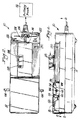
- Figure 1 is a side elevational view of a total containment connect/disconnect device for plastic tubes;
- Figure 2 is a top plan view of the device shown in Figure 1;
- Figure 3 is a top plan view of the device shown in Figures 1-2 with the cover of the device in its open position;
- Figure 4 is a right end elevational view of the device shown in Figure 3;
- Figure 5 is a perspective view of a wafer used in the device of Figures 1-4;
- Figure 6 is an end elevational view of the wafer of Figure 5 mounted in a carrier;
- Figure 7 is a side elevational view of the wafer and carrier shown in Figure 6;
- Figure 8 is a cross-sectional view taken through Figure 3 along the line 8-8;
- Figure 9 is a top plan view with the clamp mechanisms omitted to show the holder arms of the device of Figures 1-4 in one phase of operation;
- Figure 10 is a top plan view similar to Figure 9 with the clamp mechanisms illustrated;
- Figure 11 is a cross-sectional view taken through Figure 10 along the line 11-11;
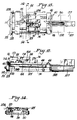
- Figure 12 is a side elevational view of the device shown in Figures 1-4 in its connect position;
- Figure 13 is a top plan view of the device shown in Figure 12;
- Figure 14 is a cross-sectional view taken through Figure 13 along the line 14-14;
- Figure 15 is a schematic showing of the sequence of operation for the tube connect technique;
- Figure 16 is a side elevational view partly in section showing a tube resulting from the connect technique;
- Figure 17 is a side elevational view of the device shown in Figures 1-4 with a tube mounted for the disconnect technique;
- Figure 18 is a top plan view of the device shown in Figure 17;
- Figure 19 is a elevational view partly in section of the device shown in Figures 17-18;
- Figure 20 is a cross-sectional view in elevation of a portion of the device shown in Figures 17-18;
- Figure 21 is a schematic showing of the sequence of operation for the tube disconnect technique;
- Figure 22 is a side elevational view partly in section showing the tube sections resulting from the tube disconnect technique;
- Figure 23 is a bottom plan view of the upper shell of the casing of the device shown in Figures 1-4;
- Figure 24 is a side elevational view of the device shown in Figures 1-4 with the cover partially opened;
- Figure 25 is a side elevational view of a portion of the device shown in Figures 1-4 showing a clamping pad disposed against a flattened welded tube in the connect mode;
- Figure 26 is a view similar to Figure 21 showing the clamping pads used for opening a flattened tube;
- Figure 27 is a front elevational view of the clamping pads shown in Figures 25-26;
- Figure 28 is a block diagram of the controller used with the device of Figures 1-4; and
- Figures 29A-29C are a flow diagram showing use of the controller of Figure 28.
-
- The present invention is related to the various techniques disclosed in the applications cited in the opening paragraph of the description and more particularly to a device capable of effectively performing the tube connect or the tube disconnect operations such as generally described in these applications. The details of the parent applications are incorporated herein by reference thereto. As illustrated herein the device for selectively connecting and disconnecting plastic tubes comprises a
welder 10 which generally includes a chassis or body member with a hinged lid orcover 12. The casing forwelder 10 may be alower shell 11 detachably secured to anupper shell 13 by suitable fasteners.Lid 12 is hinged at one end toupper shell 13.Cover 12 may be reliably held in its closed position in any suitable manner, such as by amagnetic closure 14 which is magnetically attracted to a portion of the welder body. When it is desired to usewelder 10cover 12 would be pivoted to the open position shown in Figure 3. - In general,
welder 10 operates by using a heateddisposable wafer 16 which performs a melt/wipe operation during the connect procedure and which performs a cutting operation during the disconnect procedure.Wafer 16 would be mounted in asuitable holder 18. As shown in Figures 6-7,holder 18 has a slot into whichwafer 16 is detachably mounted with thewings 20 ofwafer 16 abutting againstlower block portion 22 ofholder 18. A pair ofnotches 24 is formed betweenlower block portion 22 andupper block portion 26 ofholder 18.Wafer 16 also includes a notch or cut out 28 for purposes later described. -
Welder 10 has aslot 30 exposed from its top surface with theupstream end 32 of theslot 30 being of a sufficient width to permitwafer 16 and itsholder 18 to be inserted into the slot. The upstreamwide end 32 ofslot 30 may be considered the home position.Slot 30 engagesnotches 24 and forms a track forcarrier 18. A pair of taperedspring arms 34 are provided in the bottom ofslot 30.Arms 34 are dimensioned to fit against thewafer 16 whenholder 18 is at the end ofslot 30.Arms 34 are connected to a heater to heatwafer 16. - A
carriage 36 is located along the track formed byslot 30 remote fromhome position 32.Carriage 36 includes a spring mounted pawl 38 (Fig. 9) which engages cut out 28 ofwafer 16 to lockwafer 16 tocarriage 36 andpermit holder 18 to be moved back toward thehome position 32 whilewafer 16 remains locked tocarriage 36 thus disengagingwafer 16 fromholder 18.Carrier 18 may then be removed fromwelder 10 when it returns to thehome position 32. A spring arm 40 (Fig. 13) is located at the starting position ofcarriage 36 to lockcarriage 36 in that position untilcarriage 36 is driven in a downstream direction as later described. - Suitable heater elements connected to
arms 34heat wafer 16 whenwafer 16 is mounted tocarriage 36 whilecarriage 36 is in its starting position. - As shown in Figure 9 a
spring arm 42 is mounted at the starting position ofcarriage 36 and is urged into contact withwafer 16 whilecarriage 36 is in the starting position.Arm 42 functions as a sensor during later operation ofwelder 10 to detect the passage ofwafer 16 in a downstream direction. -
Welder 10 also includes a pair ofpivotable arms arms - As shown for example in Figure 20
clamp holder arms 44 include an off-setextension 48 which is disposed for sliding underbracket 50.Bracket 50 thus assures that the pivotedclamp holder arms 44 are maintained in their proper horizontal orientation. As also shown in Figure 20 a clamp mechanism is secured to eachholder arm 44. The clamp mechanism comprises a base clamp 52 and alid 54. Base clamp 52 is fixedly mounted to itsrespective arm 44 whilelid 54 is pivoted aboutpin 56 to base clamp 52 so that the lid can be moved to its open and closed position.Lid 54 includes ahandle portion 53 pivoted aboutpin 55 to the main portion oflid 54.Handle portion 53 is generally L-shaped with an extension 57 having aroller 60 which extends longitudinally across extension 57. Base clamp 52 includes alock lip 58.Lid 54 is moved to its closed position by graspinghandle 53 androtating lid 54 toward base clamp 52. Continued movement ofhandle 53causes roller 60 to be disposed underlock lip 58 to effectively lock theclamp lid 54 against base clamp 52. - As illustrated in various figures, such as Figure 20, a
pocket 62 is formed in base clamp 52.Pocket 62 extends completely across base clamp 52 as illustrated for example in Figures 10 and 18. It is noted that Figure 9 shows thearms 44 with the clamping mechanisms removed so that the details ofarms 44 would be more clearly illustrated. - As shown, for example, in Figure 10 a locating
wall 64 is movably mounted at the end of eachpocket 62 to close the pocket. Locatingwall 64 is of generally U-shape so that its bight or main wall portion is disposed beyond the end of itsrespective pocket 62. When atube 66 is inserted into apocket 64 thetube 66 would be moved inwardly into its respective pocket until the end of the tube abuts against locatingwall 64. This assures proper positioning of the tube for a later connect operation. Eachlid 54 would include a pair ofwall inactivating members 68 disposed for moving the upwardly spring biased locatingwall 64 in a downward direction to movewall 64 clear ofpocket 62 whenclamp lid 54 is in its closed position. - A further feature of the clamp mechanism is the provision of sensing means to assure the presence of a squashed tube and to assure the clamp being in its closed position. The details thereof are best illustrated in Figures 17-20. As shown in Figures 18 and 20 a
spring arm 70 is secured by asuitable fastener 72 to base clamp 52. Apin 74 is movably mounted in a suitable passageway in base clamp 52 and rests onspring arm 70.Pin 74 includes an annular flange 76 which would engage the shoulder 84 in base clamp 52 to limit the upward movement ofpin 74. The end ofspring arm 70 remote fromfastener 72 carries asensor flag 78 which is disposed for movement into and out of a beam from thesensor 80. Whenclamp lid 54 is in its opened position (Figures 17-18)spring arm 70 urgesflag 78 upwardly to interrupt the beam thereby indicating that the clamp mechanism is open.Clamp lid 54 carries atube contact tab 82. When the clamp mechanism is in its closed position thetube contact pad 82 would be pressed againsttube 66 and would also press againstpin 74 to movepin 74 downwardly with its flange 76 moved away from the shoulder 84 in base clamp 52. The downward movement would also causespring arm 70 to be pivoted aboutfastener 72 and moveflag 78 out of the beam fromsensor 80, thus indicating that the clamp is closed and the tube is in its proper squashed condition. It is noted that for the sake of clarity the tube is not illustrated in Figure 20 but is illustrated in Figure 19. - After the clamp mechanisms have been loaded with
tubes 66,carriage 36 is moved in a downstream direction when thewafer 16 has been heated to a predetermined temperature. - Figure 9 illustrates the
reversible motor 86 for drivingcarriage 36. As later describedmotor 86 includes amagnetic encoder 87.Motor 86 rotates anelongated drive screw 88 to move the carriage away from its starting position and back to its starting position. Aguide rod 90 is located parallel to drivescrew 88 to assure proper alignment of thecarriage 36 during its movement.Carriage motor 86 may be operated by any suitable source such as a battery pack 92 (Fig. 2). The various mechanisms for turning on the heater forwafer 16, for drivingmotor 86 and for rotatingarms 44 as well as the timing of the various operations may be controlled by a suitable controller or computer 146 as shown in Figure 29. - Controlled joint pivotable movement of
arms 44 is accomplished by a rocker mechanism best illustrated in Figures 8 and 11. Eachholder arm 44 has a rotatable ball orsphere 94 connected thereto. A pair ofrocker arms socket 100 formed in its corresponding yoke.Rocker arm 96 is pivotally mounted about the smooth end ofscrew 88.Rocker arm 98 pivots aboutguide rod 90.Rocker arm 98 is the driver arm and includes apin 104 which extends through slot 106 ofrocker arm 96.Rocker arm 96 in turn is the driven rocker arm. - A
motor 108 controls the rotational movement ofguide rod 90 which is associated withdriver rocker arm 98. Amagnetic encoder 107 is provided formotor 108. When the rocker arm is pivoted byguide pin 90,socket 100 ofrocker arm 98 rotates itsball 94 to rotate itsarm 44 in a horizontal direction.Pin 104 mounted in slot 106 in turn causes drivenrocker arm 96 to rotate which in turn causes the otherclamp support arm 44 to move horizontally in response to the seating of itsball 94 insocket 100 ofarm 96. - Another feature of the rocker arms is that the rocker arms may be used to detect that the
clamp arms 44 have been moved sufficiently close to each other so that the tube sections are in contact with the wafer. This feature is best shown in Figure 8 where thecorner 110 ofrocker arm 98 is disposed as interrupting a beam of light from asensor 112 when the clamp holder arms are moved to have the tube sections in their wafer abutting condition. - Downstream from the clamp mechanism is a
wafer removal station 114 which includes a pair of copper quenchblocks 111 dimensioned to permit thewafer 16 to be disposed between theblocks 111 whencarriage 36 is moved to its end position.Blocks 111 are spring biased toward each other by being mounted to spring arms 109 to assure contactingwafer 16 to cool the wafer. After thewafer 16 has been sufficiently cooled it can be pulled upwardly from betweenblocks 116 disconnecting thepawl 38 from notch or cut-out 28. The used wafer can then be discarded.Carriage 36 would then be moved bydrive screw 88 back to its starting position. - One of the features of
welder 10 is the inclusion of various sensors to assure thatwelder 10 is operating in its intended manner. Figures 1-2 and 23-24 illustrate a sensing arrangement for assuring that the lid or cover 12 is in its closed position. As best shown in Figure 24lid 12 includes a downwardly projectingpin 148. Theupper shell 13 has anopening 150 into whichpin 148 would enter whenlid 12 is closed onto theupper shelf portion 13 of the casing. Aphotosensor 152 is mounted inopening 150. Whenpin 148 enters theopening 150 in the condition oflid 12 being fully closed, the beam of light from theoptical sensor 152 is interrupted to detect the proper closure of cover orlid 12. - As shown in Figures 12-14
carriage 36 has an outwardly extendingarm 119 which acts as a detector for various sensors to determine different conditions ofwelder 10. For example,sensor 113A (Figure 14) is provided to indicate that thewafer 16 is properly loaded incarriage 36.Sensor 113B (Figure 13) detects the wafer being properly conditioned between clenching block 127. - Additional sensing is accomplished by means of
spring arm 125 fixed to the chassis as shown in Figures 12-14. Aflag 123 is mounted to the ends ofspring arm 125. Whenflag 123 interrupts the beam fromoptical sensor 121 this is a signal that there is no wafer in thecarriage 136. - The various sensors thus detect when the wafer is in the quench blocks, when the wafer is properly loaded and when there is no wafer in the carriage. Additionally, sensors detect when the carriage is in its home or starting position and when the carriage is in its forward most position at quenching
station 111. - An important feature of the invention is the provision of means to dissipate the aerosol that would result from the melted plastic tubes. This is done by the provision of
negative ion generators 154 mounted to the inner surface ofupper shell 13. Four such negative ion generators are illustrated. Thenegative ion generators 154 are interconnected bysolid copper wires 156 and are connected bywire 158 to a pair of diodes andcapacitors 160 associated withtransformer 162. The negative ion generators dissolve the aerosol or gases that would form from the melted tubing, such as PVC material. The dissolved gases would be attracted to thecopper wafer 16. By having aclosed cover 12 dissipation of the aerosol is assured to maintain any smoke in the closed cavity so that the aerosol would be directed to thewafer 16. - The provision of
cover 12 not only functions in assuring proper operation of the negative ion generators and in adding to the aesthetic appearance ofwelder 10, but also covers the various components ofcover 10 that should not be touched by the patient during operation ofwelder 10. Thus cover 12 adds to the safety in the operation ofwelder 10. - A further distinctive feature of
welder 10 is the inclusion ofclamp pads 164 each of which is an offset extensions ofarm 166 attached to the bottom of eachclamp lid 54. As best shown in Figures 25-27 and as also shown in Figures 10 and 17-19 eachclamp pad 164 terminates in a serrated edge 168. Theclamp pads 164 press against the tubes to flatten the tubes in a horizontal plane. Whenwelder 10 is used for the connect procedure thetubes 66 are flattened to a closed condition to form aconnected tube 134 having itsweld seam 136 in the plane indicated by the broken lines 170. It is then necessary to open the tube atweld seam 136. This can be done by openingupper clamp 54 and rotating the flattenedtube 134 about 90° so that the flattened tubes in plane 170 are now in a vertical rather than a horizonal orientation. Theupper clamp 54 is again moved in the closing direction as shown in Figure 26 and theclamp pads 164 press against theflat tube 134 to begin to pop the tubes open. The provision of the serrated edge 168 helps prevent thetube 134 from slipping back toward its horizontal orientation during its opening action. The opening of the tube joined in the connect procedure can be accomplished with the use of only one clamp pad although two clamp pads may be used if desired. - The following is the sequence of operation during the tube connect procedure. The cycle would begin at the home or rest position where no tubes are in the
welder 10 and no wafer is in the welder and wherein the clamp mechanisms are both open with the heaters off. - A
new wafer 16 would then be inserted into itsholder 18 and the unit would be mounted into theslot 30 at the top ofwelder 10. The carrier would then be advanced all the way forward where thewafer 16 would become engaged withcarriage 36. Theholder 18 would then be moved all the way back and removed fromwelder 10. This movement strips the wafer out of the wafer holder and loads it onto thecarriage 36. If the user does not go far enough the wafer would not be installed and a sensor would detect this condition as indicated by LED 115 (Fig. 1). If the user tries to feed another wafer without welding with the first wafer the carriage lock mechanism will prevent another wafer feed. Also if the carriage is not all the way back to its start position the wafer feed will be prevented. - In a typical use a consumable would have a
tube 66 attached to it. The user would first insert the tube into thepocket 62 in a base clamp 52. Thetube 66 would be installed so that its end is pushed against locatingwall 64. When theclamp lid 54 is closed and locked the locatingwall 64 is caused to swing out of the way. The user then installs the free sealed end of theother tube 66 coming, for example, from his peritoneum into the other clamp mechanism in such a manner that the sealed end of the tube butts against the other locatingwall 64 and that wall is also moved out of the way when the clamped lid is closed. The start button 116 (Fig. 2) would then be pressed. The control unit will read this signal and begin the cycle. The clamp sensors would be checked to assure that the squashed tubes are in both clamps and that theclamp lids 54 are closed as previously described. - The computer 146 operates the welder to test to see if there are two tubes properly loaded by trying to pull the clamp assemblies apart. If properly loaded this is possible to do, but if only a single tube is loaded or a tube spans both clamps it is not possible to pull the clamp assemblies apart.
- If the proper conditions are all correct the heaters are then turned on. As the temperature increases thermocouples mounted in the heaters monitor the temperature of the
wafer 16 to assure that the proper temperature is reached. When that temperature is reached the welding cycle begins. The heaters are turned off and thecarriage drive motor 86 is turned on to cause thecarriage 36 to draw thewafer 16 to the melt position. Themotor 86 is then turned off and thearm motor 108 causes the tubes to touch the hot wafer for the first time. That time is noted and saved by the controller 146. Thetubes 66 are driven into the sides of the wafer by themotor 108 at a controlled rate determined by the melt rheology. - The
carriage motor 86 is again started to again move thecarriage 36 and itswafer 16 rapidly to the weld position in thewafer removal station 111. At the same time thearm motor 108 will control the closure of the arms so that they do not attempt to form a weld until the wafer is completely clear of bothtubes 66 at which point thetubes 66 will be driven together to a known final weld point. Bothmotors - The
welder 10 includes various indicators to assure that the proper conditions are present. For example, as previously notedLED 115 indicates that the wafer is in its proper position.LED 118 would indicate that the tubes are properly loaded.LED 117 would indicate that the welder is on whenstart button 116 is pushed.LED 120 would indicate that thewelder 10 is in its connect mode when, for example,button 116 is pushed twice.LED 122 would indicate that thewelder 10 is in its disconnect mode.LED 124 would indicate that the wafer has been heated to its proper temperature. - Figure 15 schematically illustrates the sequence in operation in the tube connect procedure. As shown therein in the first phase of operation the
wafer 16 is mounted tocarriage 36 withcarriage 36 being in its start position. Tubes are mounted inarms reference numeral 126. - In the next phase of
operation carriage 36moves wafer 16 into the gap between the ends of the tubes. The tubes are moved closer together by the distance indicated by thereference numeral 128. In this position the ends of tubes are under the influence ofwafer 16. - In the next phase of operation the ends of the tubes are moved sufficiently apart to permit the
wings 20 of thewafer 16 to pass between the tubes as shown in the third step of Figure 15. The tube ends are then moved towardwafer 116 spaced apart by thedistance 130 so that the ends of the tubes become molten. Afterwafer 16 has passed beyond the tubes, 66 the tubes are in a condition to be pressed together and form aunitary tube 134 as shown in Figure 16 with the ends welded byseam 136. By squeezing at the weld seam withclamp pads 164 the tube ends of the joinedtube 134 become open and communicate with each other. - The following describes the use of
welder 10 in the disconnect procedure wherein reference might also be made to Figure 21. Again the cycle begins at the home position with no tubes in the welder. A new wafer is installed as previously indicated. The user inserts asingle tube 66A across bothpockets 62 in so installing the tube, thetube 66A extends across the pockets and forces the locatingwalls 64 out of the pockets.Clamp lids 54 are then closed and locked. - Each press of
button 116 conditions welder 10 to the next mode of operation. Thus, if the prior operation was the connect mode, the next press ofbutton 116 puts welder in its disconnect mode. - The
start button 116 is pressed and the control unit reads the signal to begin the cycle.LED 122 indicates that thewelder 10 is in the disconnect mode. The clamp sensors would be checked to assure that the tube is squashed and the clamp covers are closed. The user could test to see that there is only one tube loaded by having controller 146 try to pull the clamped assemblies apart. If correctly loaded it is not possible to do this. Only if the loading is not proper can the clamp assembly be pulled apart. When the loading is proper the heaters are turned on and the temperature monitored as previously described. At the proper temperature the cycle begins. The heaters are turned off and thecarriage motor drive 86 is turned on to cause thecarriage 36 to draw the wafer to the cut position. Thewafer 16 then melts its way through thetube 66A parting it into two sections. - When the tubes are parted the
arm motor 108 starts and causes thearms 44 to move apart to make room for thewings 20 of the wafer to get into position. Once thecarriage motor 86 has moved a wafer into position it is turned off. At this point thearm motor 108 causes the tube sections to move together since thehot wafer 16 is between the exposed ends of the tubes, however, thewings 20 of thewafer 16 plunge into the ends of the flattened tubes. Since thewafer 16 is still at a very high temperature on the order of 300°C the lumen of the exposed tube ends is fused to form a seal. At this point theclamp arms 44 are quickly drawn apart and the seals are allowed to cool. Figure 22 illustrates the twotube sections 138 with the end seals 140. - The
motor 86 is again started to move thecarriage 36 andwafer 16 rapidly to thewafer removal station 114. Thecarriage motor 86 then stops and the controller begins motoring the time to allow the seal to set and the spentwafer 16 to cool. After cooling the tube clamps are opened and the sealed tubes removed.Spent wafer 16 is discarded andcarriage 36 returns to its start location. - Figure 21 illustrates the condition of the
arms 44 which would hold thetube 66A and the position of thewafer 16 incarriage 36. In the initial stage of operation the ends ofarms 44 are spaced apart by thedistance 142. This distance is maintained while the wafer cuts through thetube 66A which spansarms wings 20 approach thearms 44 thearms 44 are moved apart to thedistance 144 to permit the wings to enter the gap between the cut tube ends. The arms are then moved toward each other so that the wings enter the molten ends of the tube sections. Again the arms are moved apart and the wings become free of the tube ends so that the wafer can move beyond the tube ends. - The above descriptions of the connect and disconnect procedures is fully automated by the use of controller or computer 146. This marks a distinct advancement over the present state of the art technology where manual operation of switches is necessary to perform connect and disconnect procedures. Figure 29 illustrates a flow block diagram showing the operation of controller 146. Any suitable controller or computer can be used. In an actual practice of the invention a Micro Controller Intel 8050 Micro 440 is used for controller 146. As shown therein the analog signals are fed to and from the controller 146 to control the operation of
welder 10. The use ofmagnetic encoders carriage motor 86 andarm motor 108 provides a means for determining exactly where the carriage and arms are at any given time. Each encoder would track the number of revolutions of the respective motor shaft which would be translated into a time and/or distance parameter for controller 146. Controller 146 would also function to determine if stub ends are in the clamp arms and if the clamp arms are in the proper spacing. For example, when themotor 108 is operated to move the arms to their closed position the arms could not be moved sufficiently close to each other if stub ends are inadvertently left in each arm since the stub ends would contact each other before the arms are moved to the closed position. - Figure 28 is a block diagram showing the interrelationship of controller 146 with the various components of
welder 10, including the operation of the arms, the carriage and the wafer. - Figures 29A-C illustrate a software program which would exemplify the use of
welder 10. In thatprogram welder 10 is controlled by a computer program which consists of four main modules: - 1. ACTIVATE DEVICE
- 2. CHECK DEVICE STATUS
- 3. GET DEVICE READY FOR TUBE LOADING
- 4. DO CONNECT OR DISCONNECT
-
- This sets initial conditions: such as clear interrupts, turn clock ON, make sure
negative ion generator 154 is OFF and set welder state to NOT READY for tube loading. It also reads the Next CYCLE information that was saved in memory from the last successful cycle. - This program module handles the START push-
button 116 event and checks the device status. Only one push-button switch (the START push-button 116) initiates CONNECT, DISCONNECT, CHECK-STATUS to COMMUNICATE with an optional external computer. This is rather unique because it eliminates four switches (power ON/OFF, connect, disconnect and start heat switch) and makes it simple to operate. Check-Device-Status program reads the sensors and identifies the type of tubing, if any, inserted in the device. If thearms 44 of thedevice 10 move from completely closed to completely open positions then thedevice 10 is empty (no tubing inserted). If thearms 44 can not move then tube type is set to be single, solid tubing. If thearms 44 move and stop at a preprogrammed valid position then the tube type is two tubes, ready for connect. - Module 2 also measures battery voltage and blinks the
power indicator 117 if battery voltage is too low for proper operation. - Initially, when power is applied, the unit is not ready for tube loading. First Module 3 blinks the TUBES indicator if tubing from previous operation was not removed. Second, Module 3 moves the
wafer carriage 36 all the way forward to wafer unload position (CLEAR WAFER routine) if a usedwafer 16 has been detected. (See Module 3A). - If the device is empty (no wafer and no tubes) then GET-DEVICE-READY routine moves the wafer carriage to home position. If CYCLE is set for connect then arms move to home position for connect and connect indicator turns ON. Otherwise, if CYCLE is set for disconnect, arms move to home position for disconnect and disconnect indicator turns ON. (See Module 3B).
- If a
wafer 16 and proper type of tubing is detected whenSTART 116 is pressed the program routine in Module 4 starts applying heat to thewafer 16. Whenwafer 16 reaches required temperature then the device makes a tubing connection or a disconnection. If current CYCLE is connect and two tubes are detected then proper arm and carriage movements are generated by module 4 to make a connection. Otherwise, if current CYCLE is disconnect and a solid, single tube is detected the device performs arm and carriage movements to severe and seal the tubing. Module 4 then sets and saves the Next Cycle in non-volatile memory. The program always alternates next cycle, that is, if current CYCLE is connect then Next Cycle will be set for disconnect or vice versa. Module 4 also counts the number of connects and disconnects made and also sets EXIT true, which means the main program will turn power OFF to conserve the battery power. Note: The START push-button turns power ON. - If the device is ready and is empty when START is pressed, that is, no wafer and no tube has been inserted, then program Module 4B will switch the current CYCLE. For example if current CYCLE is connect, CYCLE will be set to disconnect and arms will move to home position for disconnect.
Claims (16)
- A welder (10) for selectively connecting and disconnecting plastic tubes comprising a carriage (36) in said welder (10) for transporting a wafer (16) in said welder (10), a pair of arms (44) in said welder (10), each of said arms (44) having a tube (66) holding pocket (62) extending across its said arm (44), said arms (44) being movably mounted to generally align said pockets (62) with a gap therebetween, each of said arms (44) having a clamp mechanism for selectively clamping a tube (66) in its pocket (62), a wafer removal station (114) in said welder (10) downstream from said arms (44), carriage drive means (86) for moving said carriage (36) to said wafer removal station (114) with the wafer (16) first passing through said gap and then into said wafer removal station (114) to permit the wafer (16) to be removed from said carriage (36) and said carriage (36) to return to its starting location, a computer (146) for controlling the operation of said arms (44) and said carriage (36) to automate the operation of said welder (10), and including a heating assembly for heating the wafer (16) so that the wafer (16) may melt the tubes (66) during the connecting mode of operation, and an aerosol control mechanism to control the aerosol produced by the melted plastic tubes (66).
- The welder (10) of Claim 1 wherein said wafer removal station (114) includes quench blocks into which the wafer (16) is disposed by the carriage (36) after passing through said gap, and said quench blocks being part of said aerosol control mechanism.
- The welder (10) of Claim 2 wherein said aerosol control mechanism further includes negative ion generators (154) located near said quench blocks to dissipate the aerosol and cause the dissipated aerosol to be attracted to the wafer (16).
- The welder (10) of Claim 3 including a cover (12) mounted over said welder (10) to create a cavity for confining the aerosol.
- The welder (10) of Claim 4 wherein said quench blocks are made of copper.
- The welder (10) of Claim 5 wherein each of said clamp mechanism includes a base clamp (52) and a clamp lid (54) movably mounted for selective movement toward and away from said base clamp (52), and a clamp pad (164) on said clamp lid (54) for pressing against a plastic tube (66).
- The welder (10) of Claim 6 wherein said clamp pad (164) terminates in a serrated edge (168).
- The welder (10) of Claim 7 including sensing means for sensing the condition of said carriage (36) and the wafer (16).
- The welder (10) of Claim 8 wherein said computer (146) completely automates the sequence and timing of the operation of said arms (44) and said carriage (36) and of the wafer (16).
- The welder (10) of Claim 1 wherein said clamp mechanism includes a base clamp (52) and a clamp lid (54) movably mounted for selective movement toward and away from said base clamp (52), and a clamp pad (164) on said clamp lid (54) for pressing against a plastic tube (66).
- The welder (10) of Claim 11 wherein said clamp pad (164) terminates in a serrated edge (168).
- A method for selectively connecting and disconnecting plastic tubes (66) wherein during the connecting of the plastic tubes (66) the ends of the tubes (66) are clamped to a flattened condition by clamp mechanisms and the ends of the tubes (66) are melted by a heated wafer (16) and the ends of the melted tubes (66) are pressed together by manipulation of arms (44) holding the clamp mechanisms to weld the tubes (66) together at a seam, and wherein during the disconnecting mode a plastic tube (66) is inserted across clamp arms (44) and cut into individual sections by a heated wafer (16) and the ends of the cut tubes are sealed closed, wherein the connecting and disconnecting modes are performed in the same welder device (10), the wafer (16) being moved through the welder device (10) by a carriage (36), and the operation of the arms (44) and the carriage (36) being automated by a computer (146).
- The method of Claim 12 including flattening the tubes (66) during the connect mode by means of clamp pads (164) incorporated in the clamp mechanisms, after the flattened tube ends are connected together removing the clamp pads (164), away from the connected tube (66), then rotating the connected tube (66) about 90° while the connected tube (66) is in the clamp mechanisms, and then opening communication of the connected tubes (66) by pressing against the tubes (66) with at least one of the clamp pads (164).
- The method of Claim 13 including the step of preventing slippage of the rotated tube (66) by means of a serrated edge (168) on the clamp pad (164).
- A method for connecting plastic tubes (66) wherein the ends of the tubes (66) are clamped to a flattened condition by clamp mechanisms, the ends of the tubes (66) are melted by a heated wafer (16), and the ends of the melted tubes (66) are pressed together by manipulation of arms (44) holding the clamp mechanisms to weld the tubes (66) together at a seam; further comprising the step of flattening the tubes (66) by means of clamp pads (164) incorporated in the clamp mechanisms, after the flattened tube ends are connected together removing the clamp pads (164) away from the resulting connected tube (66), then rotating the connected tube (66) about 90° while the connected tube (66) is in the clamp mechanisms, then opening communication of the connected tubes (66) by pressing against the tubes (66) with at least one of the clamp pads (164).
- The method of Claim 15 including the step of preventing slippage of the rotated tube (66) by means of a serrated edge (168) on the clamp pad (164).
Applications Claiming Priority (2)
| Application Number | Priority Date | Filing Date | Title |
|---|---|---|---|
| US965875 | 1992-10-23 | ||
| US07/965,875 US5279685A (en) | 1990-08-20 | 1992-10-23 | Total containment device for connect/disconnect of plastic tubes |
Publications (2)
| Publication Number | Publication Date |
|---|---|
| EP0599057A1 EP0599057A1 (en) | 1994-06-01 |
| EP0599057B1 true EP0599057B1 (en) | 1999-12-15 |
Family
ID=25510612
Family Applications (1)
| Application Number | Title | Priority Date | Filing Date |
|---|---|---|---|
| EP93116980A Expired - Lifetime EP0599057B1 (en) | 1992-10-23 | 1993-10-20 | Total containment device for connect/disconnect of plastic tubes |
Country Status (8)
| Country | Link |
|---|---|
| US (1) | US5279685A (en) |
| EP (1) | EP0599057B1 (en) |
| JP (1) | JPH06197986A (en) |
| AT (1) | ATE187677T1 (en) |
| CA (1) | CA2109060A1 (en) |
| DE (1) | DE69327300T2 (en) |
| DK (1) | DK0599057T3 (en) |
| MX (1) | MX9306400A (en) |
Cited By (4)
| Publication number | Priority date | Publication date | Assignee | Title |
|---|---|---|---|---|
| US10143829B2 (en) | 2014-06-19 | 2018-12-04 | Fenwal, Inc. | Apparatus and method for opening and/or evaluating connection site |
| EP3412334A1 (en) | 2017-06-07 | 2018-12-12 | Fenwal, Inc. | Apparatus and method for mechanically opening a connection site |
| US10549484B2 (en) | 2010-08-18 | 2020-02-04 | Fresenius Kabi Deutschland Gmbh | Method and device for the sterile connection of pipes |
| US12179466B2 (en) | 2020-08-25 | 2024-12-31 | Fenwal, Inc. | System and method for the automated opening of a sterile tubing weld |
Families Citing this family (46)
| Publication number | Priority date | Publication date | Assignee | Title |
|---|---|---|---|---|
| US5525186A (en) * | 1990-08-20 | 1996-06-11 | Denco, Inc. | Wafer for use in the selective connecting and disconnecting of plastic tubes |
| US5256229A (en) * | 1992-10-23 | 1993-10-26 | Denco, Inc. | Sterile containment welding device for plastic tubes |
| US5674333A (en) * | 1992-10-23 | 1997-10-07 | Denco, Inc. | Total containment welding of plastic tubes |
| US5632852A (en) * | 1992-10-23 | 1997-05-27 | Denco, Inc. | Ion generator in connect/disconnect of plastic tubes |
| EP0663279A3 (en) * | 1994-01-13 | 1996-08-21 | Kureha Chemical Ind Co Ltd | Apparatus and method for welding tubular members. |
| CA2164749A1 (en) * | 1995-01-18 | 1996-07-19 | Ivars V. Ivansons | Total containment connect/disconnect device |
| IT1281774B1 (en) * | 1995-04-21 | 1998-03-03 | Tecnoideal Srl | MACHINE FOR CUTTING AND WETTING PLASTIC TUBES |
| JP3422452B2 (en) * | 1995-12-08 | 2003-06-30 | テルモ株式会社 | Tube connection device |
| US5871612A (en) * | 1997-07-10 | 1999-02-16 | Denco, Inc. | Wafer for use in selective connecting and disconnecting of plastic tubes |
| US5855731A (en) * | 1997-09-17 | 1999-01-05 | Denco, Inc. | Sterile containment welding device for plastic tubes |
| US6020574A (en) * | 1998-03-09 | 2000-02-01 | Denco, Inc. | Sterile containment welding device with self-monitoring heater unit for plastic tubes |
| US6485593B1 (en) * | 1998-10-26 | 2002-11-26 | Kurt J. Christoffersen | Sterile docking apparatus and method of use |
| US6132833A (en) * | 1999-04-06 | 2000-10-17 | Denco | Wafer for use in selective connecting and disconnecting of plastic tubes |
| EP1064960A3 (en) | 1999-06-28 | 2002-01-02 | Denco, Inc. | Hemodialysis assembly and method |
| US6913056B2 (en) * | 2002-01-31 | 2005-07-05 | Baxter International Inc. | Apparatus and method for connecting and disconnecting flexible tubing |
| AU2003261827B2 (en) * | 2002-08-30 | 2008-09-11 | Terumo Kabushiki Kaisha | Tube-joining apparatus and tube-joining method |
| US7275543B2 (en) | 2002-09-20 | 2007-10-02 | Baxter International Inc. | Coupler member for joining dissimilar materials |
| US6637489B1 (en) * | 2002-10-04 | 2003-10-28 | Denco, Inc. | Wafer for use in the selective connecting and disconnecting of plastic tubes |
| US7842769B1 (en) | 2003-06-13 | 2010-11-30 | Underground Solutions Technologies Group, Inc. | Polyvinyl chloride formulations |
| US6982051B2 (en) | 2003-06-13 | 2006-01-03 | Underground Solutions Technologies Group, Inc. | Fusion process for conduit |
| JP4046655B2 (en) * | 2003-07-04 | 2008-02-13 | テルモ株式会社 | Tube joining device |
| US7722733B2 (en) * | 2004-03-29 | 2010-05-25 | Baxter International Inc. | Method for sterile connection of tubing |
| US7243890B1 (en) * | 2005-05-05 | 2007-07-17 | United States Of America As Represented By The Secretary Of The Army | Dry powder service unit and method of use thereof |
| US7398813B2 (en) | 2006-07-31 | 2008-07-15 | Denco Inc. | Device for welding plastic tubes |
| SG183753A1 (en) * | 2007-04-13 | 2012-09-27 | Underground Solutions Technologies Group Inc | Conduit, manufacture thereof and fusion process therefor |
| US7731914B2 (en) * | 2007-07-11 | 2010-06-08 | Denco, Inc. | Ozone infection control device |
| US8167338B2 (en) * | 2007-09-24 | 2012-05-01 | Cantex, Inc. | Non-metallic raceway for wiring and fiber optic cable and method of forming raceway |
| US8708019B2 (en) * | 2009-06-10 | 2014-04-29 | Genesis Bps, Llc | Device for welding plastic tubes |
| US8066269B2 (en) * | 2009-06-22 | 2011-11-29 | Genesis Bps, Llc | Clamp locking mechanism in device for welding plastic tubes |
| US8448992B2 (en) | 2011-02-16 | 2013-05-28 | Fenwal, Inc. | Sterile docking device, medical fluid flow system with sterile docking device and method of using same |
| JP5771066B2 (en) * | 2011-05-18 | 2015-08-26 | 株式会社ジェイ・エム・エス | Tube fusing equipment |
| WO2013096038A1 (en) | 2011-12-21 | 2013-06-27 | Fenwal, Inc. | Fluid flow conduits and apparatus and methods for making and joining fluid conduits |
| US9308709B2 (en) | 2013-06-06 | 2016-04-12 | Fenwal, Inc. | Bonding apparatus and method |
| JP6285189B2 (en) * | 2014-01-24 | 2018-02-28 | テルモ株式会社 | Tube joining device |
| US9440396B2 (en) | 2014-06-19 | 2016-09-13 | Fenwal, Inc. | Sterile connection device for making multiple connections |
| US9839582B2 (en) | 2014-12-02 | 2017-12-12 | Fenwal, Inc. | Sterile connection syringe assemblies |
| US10334794B2 (en) * | 2016-02-11 | 2019-07-02 | Millbrook Capital Management Inc. | Irrigation implement |
| US11731371B2 (en) | 2021-01-25 | 2023-08-22 | Fenwal, Inc. | Sterile connection of tubing |
| EP4313561A4 (en) | 2021-03-31 | 2025-02-19 | GenesisBPS | Device for welding plastic tubes |
| US12521474B2 (en) | 2022-03-10 | 2026-01-13 | Terumo Bct, Inc. | Soft cassette with integrated features |
| US12379916B2 (en) | 2022-03-10 | 2025-08-05 | Terumo Bct, Inc. | Communications and operation control of apheresis systems |
| US12599710B2 (en) | 2022-03-10 | 2026-04-14 | Terumo Bct, Inc. | Methods and interfaces for providing donation process feedback |
| US12653937B2 (en) | 2022-03-10 | 2026-06-16 | Terumo Bct, Inc. | Apheresis system safety features |
| US12458740B2 (en) | 2022-03-10 | 2025-11-04 | Terumo Bct, Inc. | Modular serviceability sleds and interconnections |
| US12691032B2 (en) | 2022-03-10 | 2026-07-28 | Terumo Bct, Inc. | Bottle tray with magnetic coupling and load cell overload protection |
| US12478551B2 (en) | 2022-03-10 | 2025-11-25 | Terumo Bct, Inc. | Collection bottle with integrated cap, handle, and shield features |
Family Cites Families (11)
| Publication number | Priority date | Publication date | Assignee | Title |
|---|---|---|---|---|
| IL69496A0 (en) * | 1982-08-16 | 1983-11-30 | Du Pont | Automatic apparatus,system and process for making a connection between two thermoplastic resin tubes |
| US4610670A (en) * | 1983-06-13 | 1986-09-09 | E. I. Du Pont De Nemours And Company | Sterile connection process, apparatus and system |
| DE3564191D1 (en) * | 1985-07-05 | 1988-09-15 | Npbi Bv | Sterile docking process and apparatus for plastic tube portions or the like |
| DE3617849A1 (en) * | 1986-05-27 | 1987-12-03 | Hoelter Heinz | Breathing air purification apparatus with gentle electrical separation for motor vehicles |
| US4793888A (en) * | 1986-07-11 | 1988-12-27 | Morton Thiokol, Inc. | System for underwater and cold temperature bonding |
| US4753697A (en) * | 1987-02-24 | 1988-06-28 | Denco, Inc. | Total-containment sterile process and system |
| US4897138A (en) * | 1987-05-18 | 1990-01-30 | Denco, Inc. | Sealing of plastic tubes |
| US4883224A (en) * | 1988-05-18 | 1989-11-28 | Sun Shin Ching | Ashtray apparatus |
| US5158630A (en) * | 1990-08-20 | 1992-10-27 | Denco, Inc. | Total containment welding or plastic tubes |
| US5209800A (en) * | 1990-08-20 | 1993-05-11 | Denco, Inc. | Total containment welding of plastic tubes |
| US5156701A (en) * | 1990-08-20 | 1992-10-20 | Denco Inc. | Total containment welding of plastic tubes |
-
1992
- 1992-10-23 US US07/965,875 patent/US5279685A/en not_active Expired - Lifetime
-
1993
- 1993-10-04 JP JP24805193A patent/JPH06197986A/en active Pending
- 1993-10-14 MX MX9306400A patent/MX9306400A/en not_active IP Right Cessation
- 1993-10-20 AT AT93116980T patent/ATE187677T1/en active
- 1993-10-20 DE DE69327300T patent/DE69327300T2/en not_active Expired - Fee Related
- 1993-10-20 EP EP93116980A patent/EP0599057B1/en not_active Expired - Lifetime
- 1993-10-20 DK DK93116980T patent/DK0599057T3/en active
- 1993-10-22 CA CA 2109060 patent/CA2109060A1/en not_active Abandoned
Cited By (8)
| Publication number | Priority date | Publication date | Assignee | Title |
|---|---|---|---|---|
| US10549484B2 (en) | 2010-08-18 | 2020-02-04 | Fresenius Kabi Deutschland Gmbh | Method and device for the sterile connection of pipes |
| US10569478B2 (en) | 2010-08-18 | 2020-02-25 | Fresenius Kabi Deutschland Gmbh | Method and device for the sterile connection of pipes |
| US11351742B2 (en) | 2010-08-18 | 2022-06-07 | Fresenius Kabi Deutschland Gmbh | Method and device for the sterile connection of pipes |
| US10143829B2 (en) | 2014-06-19 | 2018-12-04 | Fenwal, Inc. | Apparatus and method for opening and/or evaluating connection site |
| EP3412334A1 (en) | 2017-06-07 | 2018-12-12 | Fenwal, Inc. | Apparatus and method for mechanically opening a connection site |
| US10919235B2 (en) | 2017-06-07 | 2021-02-16 | Fenwal, Inc. | Apparatus and method for mechanically opening a connection site |
| US11325321B2 (en) | 2017-06-07 | 2022-05-10 | Fenwal, Inc. | Apparatus and method for mechanically opening a connection site |
| US12179466B2 (en) | 2020-08-25 | 2024-12-31 | Fenwal, Inc. | System and method for the automated opening of a sterile tubing weld |
Also Published As
| Publication number | Publication date |
|---|---|
| ATE187677T1 (en) | 2000-01-15 |
| MX9306400A (en) | 1994-04-29 |
| CA2109060A1 (en) | 1994-04-24 |
| DE69327300D1 (en) | 2000-01-20 |
| EP0599057A1 (en) | 1994-06-01 |
| DE69327300T2 (en) | 2000-08-10 |
| DK0599057T3 (en) | 2000-06-13 |
| JPH06197986A (en) | 1994-07-19 |
| US5279685A (en) | 1994-01-18 |
Similar Documents
| Publication | Publication Date | Title |
|---|---|---|
| US5279685A (en) | Total containment device for connect/disconnect of plastic tubes | |
| EP1652653B1 (en) | Tube joining device | |
| EP1547755B1 (en) | Tube-joining apparatus and tube-joining method | |
| JP4162973B2 (en) | Tube joining device | |
| JP6928643B2 (en) | Tube joining device | |
| JPWO2018173957A1 (en) | Tube joining equipment | |
| WO2005000564A1 (en) | Tube clamp device and tube connection device | |
| JP7051811B2 (en) | Tube joining device | |
| JP6913742B2 (en) | Tube joining device | |
| JP3093887B2 (en) | Flexible tube aseptic joining device | |
| US4969969A (en) | Apparatus and method for infrared sealing of plastic strap | |
| JP2004187735A (en) | Tube joining equipment | |
| JP4139202B2 (en) | Tube joining device | |
| JP3140213B2 (en) | Flexible tube aseptic joining device | |
| JP4115262B2 (en) | Tube joining device | |
| US20240325714A1 (en) | Automatic weld/reset motion of clamps after clamp closing/opening and tube removal | |
| JPH0626877U (en) | Flexible tube aseptic joining device | |
| JP5955570B2 (en) | Aseptic bonding equipment | |
| JPH0691008A (en) | Flexible tube aseptic joining device | |
| JPH0691011A (en) | Flexible tube aseptic joining device | |
| JP7252087B2 (en) | tube splicing equipment | |
| JPH06270259A (en) | Fusion machine | |
| JP2012148035A (en) | Tube joining device | |
| HK1078293B (en) | Tube bonder |
Legal Events
| Date | Code | Title | Description |
|---|---|---|---|
| PUAI | Public reference made under article 153(3) epc to a published international application that has entered the european phase |
Free format text: ORIGINAL CODE: 0009012 |
|
| AK | Designated contracting states |
Kind code of ref document: A1 Designated state(s): AT BE CH DE DK ES FR GB GR IE IT LI LU MC NL PT SE |
|
| 17P | Request for examination filed |
Effective date: 19941129 |
|
| 17Q | First examination report despatched |
Effective date: 19970327 |
|
| GRAG | Despatch of communication of intention to grant |
Free format text: ORIGINAL CODE: EPIDOS AGRA |
|
| GRAG | Despatch of communication of intention to grant |
Free format text: ORIGINAL CODE: EPIDOS AGRA |
|
| GRAH | Despatch of communication of intention to grant a patent |
Free format text: ORIGINAL CODE: EPIDOS IGRA |
|
| GRAH | Despatch of communication of intention to grant a patent |
Free format text: ORIGINAL CODE: EPIDOS IGRA |
|
| GRAA | (expected) grant |
Free format text: ORIGINAL CODE: 0009210 |
|
| AK | Designated contracting states |
Kind code of ref document: B1 Designated state(s): AT BE CH DE DK ES FR GB GR IE IT LI LU MC NL PT SE |
|
| PG25 | Lapsed in a contracting state [announced via postgrant information from national office to epo] |
Ref country code: LI Free format text: LAPSE BECAUSE OF FAILURE TO SUBMIT A TRANSLATION OF THE DESCRIPTION OR TO PAY THE FEE WITHIN THE PRESCRIBED TIME-LIMIT Effective date: 19991215 Ref country code: IT Free format text: LAPSE BECAUSE OF FAILURE TO SUBMIT A TRANSLATION OF THE DESCRIPTION OR TO PAY THE FEE WITHIN THE PRE;WARNING: LAPSES OF ITALIAN PATENTS WITH EFFECTIVE DATE BEFORE 2007 MAY HAVE OCCURRED AT ANY TIME BEFORE 2007. THE CORRECT EFFECTIVE DATE MAY BE DIFFERENT FROM THE ONE RECORDED.SCRIBED TIME-LIMIT Effective date: 19991215 Ref country code: GR Free format text: LAPSE BECAUSE OF NON-PAYMENT OF DUE FEES Effective date: 19991215 Ref country code: ES Free format text: THE PATENT HAS BEEN ANNULLED BY A DECISION OF A NATIONAL AUTHORITY Effective date: 19991215 Ref country code: CH Free format text: LAPSE BECAUSE OF FAILURE TO SUBMIT A TRANSLATION OF THE DESCRIPTION OR TO PAY THE FEE WITHIN THE PRESCRIBED TIME-LIMIT Effective date: 19991215 Ref country code: AT Free format text: LAPSE BECAUSE OF FAILURE TO SUBMIT A TRANSLATION OF THE DESCRIPTION OR TO PAY THE FEE WITHIN THE PRESCRIBED TIME-LIMIT Effective date: 19991215 |
|
| REF | Corresponds to: |
Ref document number: 187677 Country of ref document: AT Date of ref document: 20000115 Kind code of ref document: T |
|
| REG | Reference to a national code |
Ref country code: CH Ref legal event code: EP |
|
| REF | Corresponds to: |
Ref document number: 69327300 Country of ref document: DE Date of ref document: 20000120 |
|
| REG | Reference to a national code |
Ref country code: IE Ref legal event code: FG4D |
|
| PG25 | Lapsed in a contracting state [announced via postgrant information from national office to epo] |
Ref country code: PT Free format text: LAPSE BECAUSE OF FAILURE TO SUBMIT A TRANSLATION OF THE DESCRIPTION OR TO PAY THE FEE WITHIN THE PRESCRIBED TIME-LIMIT Effective date: 20000315 |
|
| ET | Fr: translation filed | ||
| K2C3 | Correction of patent specification (complete document) published |
Effective date: 19991215 |
|
| REG | Reference to a national code |
Ref country code: DK Ref legal event code: T3 |
|
| REG | Reference to a national code |
Ref country code: CH Ref legal event code: PL |
|
| PLBE | No opposition filed within time limit |
Free format text: ORIGINAL CODE: 0009261 |
|
| STAA | Information on the status of an ep patent application or granted ep patent |
Free format text: STATUS: NO OPPOSITION FILED WITHIN TIME LIMIT |
|
| 26N | No opposition filed | ||
| PGFP | Annual fee paid to national office [announced via postgrant information from national office to epo] |
Ref country code: FR Payment date: 20011002 Year of fee payment: 9 |
|
| PGFP | Annual fee paid to national office [announced via postgrant information from national office to epo] |
Ref country code: SE Payment date: 20011003 Year of fee payment: 9 |
|
| PGFP | Annual fee paid to national office [announced via postgrant information from national office to epo] |
Ref country code: GB Payment date: 20011004 Year of fee payment: 9 Ref country code: DK Payment date: 20011004 Year of fee payment: 9 Ref country code: DE Payment date: 20011004 Year of fee payment: 9 |
|
| PGFP | Annual fee paid to national office [announced via postgrant information from national office to epo] |
Ref country code: MC Payment date: 20011005 Year of fee payment: 9 |
|
| PGFP | Annual fee paid to national office [announced via postgrant information from national office to epo] |
Ref country code: NL Payment date: 20011009 Year of fee payment: 9 |
|
| PGFP | Annual fee paid to national office [announced via postgrant information from national office to epo] |
Ref country code: LU Payment date: 20011012 Year of fee payment: 9 |
|
| PGFP | Annual fee paid to national office [announced via postgrant information from national office to epo] |
Ref country code: BE Payment date: 20011025 Year of fee payment: 9 |
|
| PGFP | Annual fee paid to national office [announced via postgrant information from national office to epo] |
Ref country code: IE Payment date: 20011030 Year of fee payment: 9 |
|
| REG | Reference to a national code |
Ref country code: GB Ref legal event code: IF02 |
|
| PG25 | Lapsed in a contracting state [announced via postgrant information from national office to epo] |
Ref country code: LU Free format text: LAPSE BECAUSE OF NON-PAYMENT OF DUE FEES Effective date: 20021020 Ref country code: GB Free format text: LAPSE BECAUSE OF NON-PAYMENT OF DUE FEES Effective date: 20021020 |
|
| PG25 | Lapsed in a contracting state [announced via postgrant information from national office to epo] |
Ref country code: SE Free format text: LAPSE BECAUSE OF NON-PAYMENT OF DUE FEES Effective date: 20021021 Ref country code: IE Free format text: LAPSE BECAUSE OF NON-PAYMENT OF DUE FEES Effective date: 20021021 |
|
| PG25 | Lapsed in a contracting state [announced via postgrant information from national office to epo] |
Ref country code: DK Free format text: LAPSE BECAUSE OF NON-PAYMENT OF DUE FEES Effective date: 20021031 Ref country code: BE Free format text: LAPSE BECAUSE OF NON-PAYMENT OF DUE FEES Effective date: 20021031 |
|
| BERE | Be: lapsed |
Owner name: *DENCO INC. Effective date: 20021031 |
|
| PG25 | Lapsed in a contracting state [announced via postgrant information from national office to epo] |
Ref country code: NL Free format text: LAPSE BECAUSE OF NON-PAYMENT OF DUE FEES Effective date: 20030501 Ref country code: MC Free format text: LAPSE BECAUSE OF NON-PAYMENT OF DUE FEES Effective date: 20030501 Ref country code: DE Free format text: LAPSE BECAUSE OF NON-PAYMENT OF DUE FEES Effective date: 20030501 |
|
| EUG | Se: european patent has lapsed | ||
| REG | Reference to a national code |
Ref country code: DK Ref legal event code: EBP |
|
| GBPC | Gb: european patent ceased through non-payment of renewal fee |
Effective date: 20021020 |
|
| PG25 | Lapsed in a contracting state [announced via postgrant information from national office to epo] |
Ref country code: FR Free format text: LAPSE BECAUSE OF NON-PAYMENT OF DUE FEES Effective date: 20030630 |
|
| NLV4 | Nl: lapsed or anulled due to non-payment of the annual fee |
Effective date: 20030501 |
|
| REG | Reference to a national code |
Ref country code: IE Ref legal event code: MM4A |
|
| REG | Reference to a national code |
Ref country code: FR Ref legal event code: ST |