EP0598641A1 - Device for un-stacking thin, stacked objects - Google Patents
Device for un-stacking thin, stacked objects Download PDFInfo
- Publication number
- EP0598641A1 EP0598641A1 EP93402709A EP93402709A EP0598641A1 EP 0598641 A1 EP0598641 A1 EP 0598641A1 EP 93402709 A EP93402709 A EP 93402709A EP 93402709 A EP93402709 A EP 93402709A EP 0598641 A1 EP0598641 A1 EP 0598641A1
- Authority
- EP
- European Patent Office
- Prior art keywords
- unstacking
- speed
- drum
- detection
- measurement
- Prior art date
- Legal status (The legal status is an assumption and is not a legal conclusion. Google has not performed a legal analysis and makes no representation as to the accuracy of the status listed.)
- Withdrawn
Links
- 238000005259 measurement Methods 0.000 claims abstract description 12
- 230000001133 acceleration Effects 0.000 claims abstract description 5
- 238000001514 detection method Methods 0.000 claims description 19
- 238000009826 distribution Methods 0.000 claims description 6
- 230000007257 malfunction Effects 0.000 claims description 6
- 238000010079 rubber tapping Methods 0.000 claims description 5
- 239000000523 sample Substances 0.000 claims description 5
- 238000011144 upstream manufacturing Methods 0.000 claims description 5
- 230000007423 decrease Effects 0.000 claims description 4
- 230000009467 reduction Effects 0.000 claims description 2
- 230000008859 change Effects 0.000 description 4
- 238000010586 diagram Methods 0.000 description 4
- 230000000694 effects Effects 0.000 description 4
- 241001417494 Sciaenidae Species 0.000 description 3
- 230000001934 delay Effects 0.000 description 3
- 230000004913 activation Effects 0.000 description 2
- 230000006978 adaptation Effects 0.000 description 2
- 230000007547 defect Effects 0.000 description 2
- 238000006073 displacement reaction Methods 0.000 description 2
- 238000001914 filtration Methods 0.000 description 2
- 230000002093 peripheral effect Effects 0.000 description 2
- 238000003825 pressing Methods 0.000 description 2
- 238000005096 rolling process Methods 0.000 description 2
- 230000002159 abnormal effect Effects 0.000 description 1
- 238000010521 absorption reaction Methods 0.000 description 1
- 230000009849 deactivation Effects 0.000 description 1
- 235000021183 entrée Nutrition 0.000 description 1
- 239000000284 extract Substances 0.000 description 1
- 239000000463 material Substances 0.000 description 1
- 238000000034 method Methods 0.000 description 1
- 238000007747 plating Methods 0.000 description 1
- 230000008569 process Effects 0.000 description 1
- 238000004064 recycling Methods 0.000 description 1
- 230000000284 resting effect Effects 0.000 description 1
- 238000000926 separation method Methods 0.000 description 1
- 230000003068 static effect Effects 0.000 description 1
- 238000003860 storage Methods 0.000 description 1
- 238000006467 substitution reaction Methods 0.000 description 1
- 230000002123 temporal effect Effects 0.000 description 1
Images

Classifications
-
- B—PERFORMING OPERATIONS; TRANSPORTING
- B65—CONVEYING; PACKING; STORING; HANDLING THIN OR FILAMENTARY MATERIAL
- B65H—HANDLING THIN OR FILAMENTARY MATERIAL, e.g. SHEETS, WEBS, CABLES
- B65H3/00—Separating articles from piles
- B65H3/08—Separating articles from piles using pneumatic force
- B65H3/10—Suction rollers
-
- B—PERFORMING OPERATIONS; TRANSPORTING
- B65—CONVEYING; PACKING; STORING; HANDLING THIN OR FILAMENTARY MATERIAL
- B65H—HANDLING THIN OR FILAMENTARY MATERIAL, e.g. SHEETS, WEBS, CABLES
- B65H7/00—Controlling article feeding, separating, pile-advancing, or associated apparatus, to take account of incorrect feeding, absence of articles, or presence of faulty articles
- B65H7/02—Controlling article feeding, separating, pile-advancing, or associated apparatus, to take account of incorrect feeding, absence of articles, or presence of faulty articles by feelers or detectors
-
- B—PERFORMING OPERATIONS; TRANSPORTING
- B65—CONVEYING; PACKING; STORING; HANDLING THIN OR FILAMENTARY MATERIAL
- B65H—HANDLING THIN OR FILAMENTARY MATERIAL, e.g. SHEETS, WEBS, CABLES
- B65H2511/00—Dimensions; Position; Numbers; Identification; Occurrences
- B65H2511/50—Occurence
- B65H2511/51—Presence
- B65H2511/514—Particular portion of element
-
- B—PERFORMING OPERATIONS; TRANSPORTING
- B65—CONVEYING; PACKING; STORING; HANDLING THIN OR FILAMENTARY MATERIAL
- B65H—HANDLING THIN OR FILAMENTARY MATERIAL, e.g. SHEETS, WEBS, CABLES
- B65H2511/00—Dimensions; Position; Numbers; Identification; Occurrences
- B65H2511/50—Occurence
- B65H2511/52—Defective operating conditions
-
- B—PERFORMING OPERATIONS; TRANSPORTING
- B65—CONVEYING; PACKING; STORING; HANDLING THIN OR FILAMENTARY MATERIAL
- B65H—HANDLING THIN OR FILAMENTARY MATERIAL, e.g. SHEETS, WEBS, CABLES
- B65H2513/00—Dynamic entities; Timing aspects
- B65H2513/10—Speed
-
- B—PERFORMING OPERATIONS; TRANSPORTING
- B65—CONVEYING; PACKING; STORING; HANDLING THIN OR FILAMENTARY MATERIAL
- B65H—HANDLING THIN OR FILAMENTARY MATERIAL, e.g. SHEETS, WEBS, CABLES
- B65H2513/00—Dynamic entities; Timing aspects
- B65H2513/10—Speed
- B65H2513/11—Speed angular
-
- B—PERFORMING OPERATIONS; TRANSPORTING
- B65—CONVEYING; PACKING; STORING; HANDLING THIN OR FILAMENTARY MATERIAL
- B65H—HANDLING THIN OR FILAMENTARY MATERIAL, e.g. SHEETS, WEBS, CABLES
- B65H2553/00—Sensing or detecting means
- B65H2553/60—Details of intermediate means between the sensing means and the element to be sensed
- B65H2553/61—Mechanical means, e.g. contact arms
-
- B—PERFORMING OPERATIONS; TRANSPORTING
- B65—CONVEYING; PACKING; STORING; HANDLING THIN OR FILAMENTARY MATERIAL
- B65H—HANDLING THIN OR FILAMENTARY MATERIAL, e.g. SHEETS, WEBS, CABLES
- B65H2701/00—Handled material; Storage means
- B65H2701/10—Handled articles or webs
- B65H2701/13—Parts concerned of the handled material
- B65H2701/131—Edges
- B65H2701/1311—Edges leading edge
-
- B—PERFORMING OPERATIONS; TRANSPORTING
- B65—CONVEYING; PACKING; STORING; HANDLING THIN OR FILAMENTARY MATERIAL
- B65H—HANDLING THIN OR FILAMENTARY MATERIAL, e.g. SHEETS, WEBS, CABLES
- B65H2701/00—Handled material; Storage means
- B65H2701/10—Handled articles or webs
- B65H2701/13—Parts concerned of the handled material
- B65H2701/131—Edges
- B65H2701/1313—Edges trailing edge
-
- B—PERFORMING OPERATIONS; TRANSPORTING
- B65—CONVEYING; PACKING; STORING; HANDLING THIN OR FILAMENTARY MATERIAL
- B65H—HANDLING THIN OR FILAMENTARY MATERIAL, e.g. SHEETS, WEBS, CABLES
- B65H2701/00—Handled material; Storage means
- B65H2701/10—Handled articles or webs
- B65H2701/19—Specific article or web
- B65H2701/1916—Envelopes and articles of mail
Definitions
- the present invention relates to a unitary dispensing device for stacked thin objects such as letters or the like.
- Such a device also called unstacking device, comprises unstacking means such as a vacuum drum to communicate an acceleration to an object at the head of the stack and present it to a conveying device which routes it to a treatment station. , sorting or whatever.
- unstacking means such as a vacuum drum to communicate an acceleration to an object at the head of the stack and present it to a conveying device which routes it to a treatment station. , sorting or whatever.
- Such a distribution device is notably described in document FR-A-2 181 523.
- a destacking device must have the highest possible flow rate, but this objective encounters many difficulties because the dimensions, the weight and the materials of thin objects are not homogeneous and can, within a stack, vary within some forks.
- the invention aims to provide a unitary distribution device for stacked thin objects which makes it possible to obtain a flow rate of objects substantially higher than that of the devices of the prior art while offering very high availability and requiring only a number very few operators to ensure proper operation.
- the subject of the invention is a device for the unitary distribution of stacked thin objects, comprising unstacking means for communicating an acceleration to an object at the head of the pile, characterized in that it comprises means for measuring the instantaneous speed of said object at the head of the stack during its ejection from the device by said unstacking means and means for controlling the drive of the next object by said unstacking means as a function of the speed data of said object at the head of the stack provided by said measuring means.
- Measuring the speed of thin objects during their ejection from the unstacking device makes it possible to predict their movement and thus to control the unstacking of the next object before the object being unstacked has left the unstacking device. Thanks to this possibility of anticipating on the unstacking command of the next object, the spacing between objects can be significantly reduced and the flow increased.
- said measurement means comprise at least one continuous speed measurement sensor comprising, for example, a rotary contact measurement probe, arranged upstream of said unstacking means.
- said probe comprises a low inertia caster comprising an elastic bandage with a high coefficient of friction.
- This bandage absorbs the unevenness of relief on the surface of thin objects and ensures rolling without sliding so that the speed of rotation of the wheel is a faithful image of the instantaneous linear speed of the object being unstacking.
- the speed information of the objects can be provided by a tachometric generator integral in rotation with the caster.
- control means are adapted to detect a decrease in the speed measured following the passage of the rear edge of an object being unstacked in front of said measurement means and to control the drive. of the next object within a predetermined period of time as from said speed reduction detection.
- the detection of the rear edge of an object takes place while it is still being unstacked, and not at the outlet of the distribution device, which makes it possible to control the unstacking of the next object in advance while being assured of the correct course unstacking in progress thanks to the speed measurement made between setting the object in motion and detecting its rear edge.
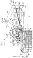
- a supply device 1 conveys a stack of thin objects 2, such as letters, to a unitary distribution or unstacking device 3 which extracts them one by one from the stack to present them to an output conveyor 4, which routes to a storage, processing or other station (not shown).
- the feeding device 1 comprises a conveyor 5 with belts moved in the direction indicated by the arrow 6 by an electric motor 7.
- the plies 2 arrive in a buffer zone 8 where they are pushed against a roller 9 driven in rotation by an electric motor 10.
- the rotation of the roller 9 has the effect of driving upwards the objects 2 which are in abutment against it and of bringing them into a third zone 11 in which they rest in the state uncompressed on a step (not shown).
- the supply device 1 is described in more detail in French patent application No. 92 07801 filed on June 25, 1992 to which reference may be made.
- the feed device 1 has a side wall 12, hereinafter referred to as a jogging edge, consisting of a sheet or the like with a low coefficient of friction arranged vertically in the direction of the arrow 6 and stopping at a distance from a wall 13 constituting the bearing face of the unstacking device 3.
- the walls 12 and 13 thus form between them a slot 14 through which the thin objects are transferred from the head of the stack to the outlet conveyor 4.
- the objects 2 stacked on the conveyor 5 are in principle supported by their front edge against the jogging edge 12.
- the unstacking device 3 conventionally comprises a perforated drum 15 rotatably mounted around a cylindrical part 16 in which is formed a chamber 17 communicating, on the one hand with a suction nozzle 18, on the other hand with a source depression 19 with interposition of a control solenoid valve 20.
- the nozzle 18 has the form of a slot opening out through an opening centered on a radial plane in line with a window 21 formed in the support wall 13 and through which the drum 15 projects slightly.
- the drum 15 when the drum 15 rotates in the direction indicated by the arrow 22 and that a vacuum is applied to the nozzle 18 under the control of the solenoid valve 20, a thin object resting against the wall 13 is pressed against the surface of the drum moving past the nozzle 18 and driven through the slot 14 towards the conveyor
- the drum 15 is arranged as close as possible to the outlet 14 of the unstacking device so as to be able to bring the objects 2 of the minimum admissible size at a nominal speed as high as possible, in order to maximize the flow of the assembly 1, 3 and 4.
- the wall 13 forms one of the faces of a suction box 23 connected to a vacuum source 24.
- the suction box 13 Immediately upstream of the drum 15 relative to the direction of ejection of the objects 2, the suction box 13 houses a vacuum re-pressing drum 25 as well as a speed sensor 26 mounted behind a perforated pallet 27 capable of making small displacements relative to the wall 13 and resiliently urged projecting relative thereto by means of a member fixing 28 such as a strain gauge as described in the French patent application No. 92 07801 cited above.
- the jogging drum and the speed sensor 26 have been shown side by side in the diagrammatic view of FIG. 1.
- the jogging drum 25 is preferably mounted substantially above the sensor. speed as shown in Figure 2.
- the movable perforated pallet 27 is arranged below a perforated area 29 of the support wall 13 and in this area 29 is formed an elongated vertical window 30 in which scrolls through the perforated wall of the tracker drum 25.
- the jogging drum 25 is preferably of the type described in French patent application FR-A-2 657 856 to which reference may be made for a more detailed description. According to the teaching of this document, the wall of the drum 25 is perforated in a limited angular sector of its circumference and a depression is permanently applied to an inner nozzle located to the right of the window 30 through which the perforated part of the drum comes to slightly protrude when the latter is rotated.
- the jogging drum 25 is capable of being driven in rotation from the drum 15 by means of a clutch 31 connected, on the one hand to the jogging drum 25 by a belt 32, on the other hand to the drum 15 by a belt 33
- the clutch 31 is for example of the electromagnetic type.
- the pallet 27 is pierced with a horizontal light 34 through which, as shown in FIG. 3, projects a wheel 35 constituting the feeler of the speed sensor 26.
- This wheel 35 is preferably a very light rim surrounded by an elastic peripheral bandage with a high coefficient of friction allowing strong adhesion to thin objects 2 and the absorption of reliefs of the order of, for example, 1 mm.
- the caster 35 is integral in rotation with a vertical axis 36 rotatably mounted between the yoke-like ends of an oscillating arm 37, by means of rolling bearings 38.
- the axle 36 is integral at its lower end with a suspended miniature tachometer 39, the housing of which is fixed to a lug 40 extending vertically downward from the arm 37.
- the oscillating arm 37 is articulated in an intermediate part of its length around a vertical axis 41 carried by a fixed support 42 and the end of the arm 37 opposite to that carrying the caster 35 is fixed to a spring 43 tending to urge the caster 35 projecting through the light 34.
- a friction shoe (not shown) is provided on the axis 36 to ensure a static friction torque and allow a defined speed drop of the caster 35 when the latter is no longer in contact with a thin object 2.
- the roller 35, and therefore the sensor 26, must be placed close enough to the outlet 14 of the unstacking device 3 so that an object of length admissible minimum reaches its nominal speed before its rear edge leaves the caster.
- the caster must be far enough from the outlet 14 so that the detection of the rear edge of the objects 2 by the sensor 26 (by detection of a drop in the speed of the caster 35 as will be explained below) has place with an advance which is sufficient to predict the movement of the object being unstacked and generate, before it actually leaves the unstacking device, the unstacking command for the next object, in order to overcome the various delays which intervene between the unstacking command and the setting in motion of an object.
- the position of the sensor 26 is therefore a compromise depending on the operating parameters imposed.
- a shoe 44 Located downstream of the outlet slot 14 and upstream of the outlet conveyor 4 are provided, on either side of the path for transporting thin objects, a shoe 44 having at least one surface with a high coefficient of friction, stressed elastically against a wedge-shaped fixed shoe 45.
- the fixed shoe 45 has, facing the shoe 44, a surface with a low coefficient of friction situated substantially in the extension of the wall 13 and substantially matches the curvature of the drum 15 on one of its sides.
- the shoe 44 is adapted to be pushed elastically from the side opposite to the shoe 45 by the front edge of a thin object when the latter is being ejected by the unstacking drum 15.
- the role of the shoe 44 and shoe 45 device is to promote the separation between the object at the head of the pile and the next object during an unstacking sequence.
- Such a device is described in detail in French patent application FR-A-2 523 099 to which reference may be made.
- the shoe 45 carries a photoelectric cell 46 which has the function of detecting, at the outlet of the unstacking device 3, the passage of the front edge and the rear edge of an object being unstacked.
- the outlet conveyor 4 comprises a first section made up of perforated belts 47 and 48 having substantially parallel or slightly divergent strands on a first section extending from the outlet 14 of the unstacking device 3, while in a second downstream section the strand of the belt 48 diverges appreciably from the rectilinear strand of the belt 47.
- the rectilinear strand of the belt 47 passes in front of suction boxes designated as a whole by the reference 49, while, in the second section, the divergent strand of the belt 48 passes in front of suction boxes 50.
- a V-shaped deflector 51 is arranged downstream of the point of divergence of the strands opposite the belts 47 and 48 and makes it possible to guide thin objects, from one side towards a second section of the output conveyor consisting of belts 52 and 53, on the other side towards a recycling station (not shown).
- the drum 15 and the perforated belts 47 and 48 are rotated from a common electric motor 54 via drive belts 55, 56 and 57 respectively.
- the motor 54 is coupled to a tachometer generator 58 making it possible to measure and control very precisely the speeds of the drum 15 and of the belts 47 and 48.
- the peripheral speed of the drum 15 is a few percent less than the speed of belts 47 and 48.
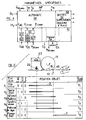
- the reference 60 designates a programmable automaton making it possible to selectively control the application of a vacuum to the drum 15 and driving the jogging drum 25 as a function of programmed parameters and of the information supplied by the speed sensor 26 and the cell 46.
- the block 61 designates an interface between the sensors and actuators and the automaton 60.
- the block 68 is a supervision unit controlled by the automaton 60 to indicate to an operator the abnormal operating states of the unstacking device 3.
- Inputs D C and M V respectively control the piecemeal operation of the unstacking device and its idling.
- Block 61 is an interface between the automaton 60 and the sensors and actuators of the unstacking device 1.
- the interface 61 receives the output signal S46 from cell 46 which, after filtering and formatting at 62 and 63, forms a signal logic E46 taking logic state 1 or 0 depending on whether or not a thin object is in front of the cell.
- the window comparator 66 compares the speed measured by the wheel 35 with threshold values ⁇ min and ⁇ max functions of the speed of rotation communicated to the drum 15 by the motor 54.
- the window comparator produces a first logic signal E ⁇ min which is at level 0 when the measured speed of the caster 35 is less than the threshold ⁇ min and at level 1 otherwise, and a second logic signal E ⁇ max which takes the value 0 when the measured speed of the caster 35 is less than threshold ⁇ max and value 1 otherwise.
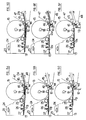
- FIG. 5A shows the unstacking device while a thin object 2 A is being ejected by the unstacking drum 15.
- the next object 2 B of the stack is during plating against the pallet 27 under the effect of the suction force which is exerted in the box 23.
- the sensor wheel 26 is immobilized in rotation by its contact with the object 2 B which pushes it gradually towards the inside of the box as the object 2 B is pressed against the support wall 13.
- the object 2 B is in the initial unstacking position, that is to say it is pressed against the support wall 13 under the effect of the suction prevailing in the box 23 and that it thus pushes the pallet 27 and the sensor wheel 26 in the plane of the wall 13.
- the front edge of the object 2 B is in the jogging position, namely in the plane of the edge 12 and close immediately from skate 44.
- the sensor 26 continuously measures the speed of the object and provides this information to the automaton 60.
- the edge rear of the object 2 B escapes from the wheel 35 of the speed sensor 26, the speed of rotation of the latter suddenly decreases due to its low inertia and, possibly, of the friction pad provided on its axis 36.
- the treatment carried out in 64, 65 and 66 the passage of the rear edge of the object 2 B at the level of the sensor 26 is detected when the speed measured by the sensor 26 drops below the set value ⁇ max .
- This detection makes it possible to launch by anticipation, within a determined period, the unstacking of the next object as will be explained with reference to FIG. 6.
- the speed sensor must be placed close enough to the shore 12 so that, in the normal operating conditions and for objects having the minimum admissible length, the speed of the caster 35 reaches the value ⁇ max before the rear edge of the object comes before the speed sensor.
- the object 2 B is being removed from the unstacking device 3 at the nominal speed fixed by the motor 54 and a new object 2 C is in position for its unstacking.
- FIG. 5E shows an object 2 M being unstacked while the next object 2 N pressing against the wall 13 has a jogging defect: its front edge is substantially distant from the jogging edge 12 and no part of the object 2 N is not located to the right of the nozzle 18 so that in the next unstacking sequence object 2 N will not be driven by the unstacking drum 15.
- This defect is detected by the fact that after the 'sending to the solenoid valve 20 of an unstacking control slot, the caster 35 of the sensor 26 does not reach the set value ⁇ min within a predetermined period. Consequently, the automaton 60 controls the tightening of the clutch 31 so as to cause a rotation of one revolution of the jogging drum 25.
- the latter the surface of which is perforated over a given angular sector, thus causes a controlled displacement of the object 2 N over a length measured by the speed sensor 26, a length which is, for example at most 30 mm.
- the retacking process is repeated until the object is sufficiently advanced (FIG. 5F) to be then driven by the drum 15.
- the supervision unit 68 associated with the automaton 60 generates a re-tapping fault message.
- FIG. 6 illustrates different states P1 to P6 of the automaton 60 for different positions of an object 2, positions which are identified with respect to the device unstacking 3 (whose jogging drum 25 has not been shown for clarity).
- the object 2 is ready to be unstacked, its front edge being assumed to be in or in the vicinity of the plane of the jogging edge 12.
- the cell 46 does not detect any object and the roller 35 is immobilized.
- the signals E46, E ⁇ min and E ⁇ max are therefore in logic state 0.
- the automaton 60 starts a timer T1 which is a function, in particular , nominal pitch P N and delays R t and t r .
- FIG. 7 shows the evolution of the speed of the caster 35 from the instant t0 of application of a control slot C D to the solenoid valve 20.
- R t represents a pure delay corresponding to the time which separates the instant of application of the control slot at the solenoid valve 20 from that of the effective establishment of the vacuum in the nozzle 18;
- t r represents the delay which separates the instant of effective establishment of the vacuum in the nozzle 18 from the instant of effective entrainment of an object 2 by the drum 15.
- the time delay T1 of state P1 represents the time within which the unstacking command of the object 2 must intervene after the trailing edge of the previous object has been detected by the speed sensor 26. If the unstacking command C D does not intervene before the end of the timer T1, the supervision unit 68 emits a malfunction signal.
- the front edge of the object 2 is detected by the cell 46 and the signal E46 goes from level 0 to level 1.
- the detection of the front edge must take place within a time T2 as a function of the delay R t and the time required for the leading edge of an object of maximum permissible weight to move from position P1 to position P2. If the leading edge is not detected within the time T2, the supervision unit 68 emits a malfunction signal.
- the automaton controls, within an appropriate period, the unstacking of the next object in anticipation of the subsequent movement of the object 2 in unstacking course.
- the state P6 corresponds to the detection by the cell 46 of the rear edge of the object 2 during unstacking. This detection causes the return of the signal E46 from level 1 to level 0, after the signal E ⁇ min has passed from level 1 to level 0 between the states P5 and P6. Detection of the rear edge of the object unstacked by the cell 46 must intervene within a maximum delay T6 from the instant t o .
- the unstacking device which has just been described makes it possible to ensure a throughput of twenty letters per second at a speed of five meters per second for letters of length between 125 and 265 mm with an average length 200 mm. Thanks to the prediction of the movement of objects during unstacking and to the advance control of unstacking of the next object which allows the device according to the invention to ensure, the spacing between consecutive objects can be reduced to 50 mm, or a temporal spacing of 7 milliseconds against 35 milliseconds for the device of the state of the art which is mentioned at the beginning of this description.
Abstract
Description
La présente invention concerne un dispositif de distribution unitaire d'objets minces empilés tels que des lettres ou similaires.The present invention relates to a unitary dispensing device for stacked thin objects such as letters or the like.
Un tel dispositif, également appelé dispositif de dépilage, comprend des moyens de dépilage tels qu'un tambour à dépression pour communiquer une accélération à un objet en tête de pile et le présenter à un dispositif de convoyage qui l'achemine vers un poste de traitement, de tri ou autre. Un tel dispositif de distribution se trouve notamment décrit dans le document FR-A-2 181 523.Such a device, also called unstacking device, comprises unstacking means such as a vacuum drum to communicate an acceleration to an object at the head of the stack and present it to a conveying device which routes it to a treatment station. , sorting or whatever. Such a distribution device is notably described in document FR-A-2 181 523.
Un dispositif de dépilage doit présenter un débit le plus élevé possible mais cet objectif se heurte à de nombreuses difficultés car les dimensions, le poids et les matériaux des objets minces ne sont pas homogènes et peuvent, dans une pile, varier à l'intérieur de certaines fourchettes. C'est ainsi que des dispositifs de dépilage utilisés à ce jour dans le domaine du tri postal permettant d'obtenir un débit de dix lettres par seconde avec une vitesse de convoyage de 3,2 mètres par seconde, un pas de 320 mm et une longueur maximale de lettre de 210 mm.A destacking device must have the highest possible flow rate, but this objective encounters many difficulties because the dimensions, the weight and the materials of thin objects are not homogeneous and can, within a stack, vary within some forks. Thus unstacking devices used to date in the field of postal sorting to obtain a throughput of ten letters per second with a conveying speed of 3.2 meters per second, a step of 320 mm and a maximum letter length of 210 mm.
L'invention vise à fournir un dispositif de distribution unitaire d'objets minces empilés qui permette d'obtenir un débit des objets sensiblement supérieur à celui des dispositifs de la technique antérieure tout en offrant une disponibilité très élevée et en ne nécessitant qu'un nombre très réduit d'opérateurs pour en assurer le bon fonctionnement.The invention aims to provide a unitary distribution device for stacked thin objects which makes it possible to obtain a flow rate of objects substantially higher than that of the devices of the prior art while offering very high availability and requiring only a number very few operators to ensure proper operation.
A cet effet, l'invention a pour objet un dispositif de distribution unitaire d'objets minces empilés, comprenant des moyens de dépilage pour communiquer une accélération à un objet en tête de pile, caractérisé en ce qu'il comprend des moyens pour mesurer la vitesse instantanée dudit objet en tête de pile pendant son éjection hors du dispositif par lesdits moyens de dépilage et des moyens pour commander l'entraînement de l'objet suivant par lesdits moyens de dépilage en fonction des données de vitesse dudit objet en tête de pile fournies par lesdits moyens de mesure.To this end, the subject of the invention is a device for the unitary distribution of stacked thin objects, comprising unstacking means for communicating an acceleration to an object at the head of the pile, characterized in that it comprises means for measuring the instantaneous speed of said object at the head of the stack during its ejection from the device by said unstacking means and means for controlling the drive of the next object by said unstacking means as a function of the speed data of said object at the head of the stack provided by said measuring means.
La mesure de vitesse des objets minces pendant leur éjection du dispositif de dépilage permet de prédire leur mouvement et de commander ainsi le dépilage de l'objet suivant avant que l'objet en cours de dépilage soit sorti du dispositif de dépilage. Grâce à cette possibilité d'anticiper sur la commande de dépilage de l'objet suivant, l'espacement entre objets peut être sensiblement réduit et le débit accru.Measuring the speed of thin objects during their ejection from the unstacking device makes it possible to predict their movement and thus to control the unstacking of the next object before the object being unstacked has left the unstacking device. Thanks to this possibility of anticipating on the unstacking command of the next object, the spacing between objects can be significantly reduced and the flow increased.
Suivant une caractéristique de l'invention, lesdits moyens de mesure comprennent au moins un capteur de mesure continue de vitesse comportant, par exemple, un palpeur rotatif de mesure par contact, disposé en amont desdits moyens de dépilage.According to a characteristic of the invention, said measurement means comprise at least one continuous speed measurement sensor comprising, for example, a rotary contact measurement probe, arranged upstream of said unstacking means.
De préférence, ledit palpeur comprend une roulette à faible inertie comportant un bandage élastique à coefficient de frottement élevé. Ce bandage permet d'absorber les inégalités de relief à la surface des objets minces et d'assurer un roulement sans glissement de sorte que la vitesse de rotation de la roulette est une image fidèle de la vitesse linéaire instantanée de l'objet en cours de dépilage. L'information de vitesse des objets peut être fournie par une génératrice tachymétrique solidaire en rotation de la roulette.Preferably, said probe comprises a low inertia caster comprising an elastic bandage with a high coefficient of friction. This bandage absorbs the unevenness of relief on the surface of thin objects and ensures rolling without sliding so that the speed of rotation of the wheel is a faithful image of the instantaneous linear speed of the object being unstacking. The speed information of the objects can be provided by a tachometric generator integral in rotation with the caster.
Suivant une forme préférée de réalisation de l'invention, les moyens de commande sont adaptés pour détecter une diminution de la vitesse mesurée consécutivement au passage du bord arrière d'un objet en cours de dépilage devant lesdits moyens de mesure et pour commander l'entraînement de l'objet suivant dans un délai prédéterminé à compter de ladite détection de diminution de vitesse. Ainsi, la détection du bord arrière d'un objet a lieu alors que celui-ci est encore en cours de dépilage, et non à la sortie du dispositif de distribution, ce qui permet de commander le dépilage de l'objet suivant par anticipation tout en étant assuré du déroulement correct du dépilage en cours grâce à la mesure de vitesse effectuée entre la mise en mouvement de l'objet et la détection de son bord arrière.According to a preferred embodiment of the invention, the control means are adapted to detect a decrease in the speed measured following the passage of the rear edge of an object being unstacked in front of said measurement means and to control the drive. of the next object within a predetermined period of time as from said speed reduction detection. Thus, the detection of the rear edge of an object takes place while it is still being unstacked, and not at the outlet of the distribution device, which makes it possible to control the unstacking of the next object in advance while being assured of the correct course unstacking in progress thanks to the speed measurement made between setting the object in motion and detecting its rear edge.
D'autres caractéristiques et avantages de l'invention ressortiront de la description qui va suivre d'un mode de réalisation donné uniquement à titre d'exemple et illustré par les dessins annexés sur lesquels :
- la figure 1 est une vue schématique en plan d'un dispositif de dépilage selon l'invention associé à un dispositif d'alimentation et à un convoyeur de sortie ;
- la figure 2 est une vue partielle en élévation frontale du dispositif de dépilage de la figure 1 ;
- la figure 3 est une vue partielle en élévation frontale à plus grande échelle d'une partie de la face d'appui de la figure 2 ;
- la figure 4 est un schéma-bloc illustrant la structure et les entrées/sorties d'un dispositif de pilotage du dispositif de dépilage selon les figures 1 à 3 ;
- les figures 5A à 5F sont des vues schématiques simplifiées similaires à la figure 1 illustrant le dispositif de dépilage dans différentes phases de fonctionnement ;
- la figure 6 est un diagramme d'état associé à une vue schématique en plan du dispositif de dépilage et illustrant les différentes séquences de dépilage mises en oeuvre grâce au dispositif de pilotage de la figure 4 ; et
- la figure 7 est un diagramme illustrant l'évolution en fonction du temps de la vitesse d'un palpeur en contact avec un objet mince pendant une partie de la phase de dépilage.
- Figure 1 is a schematic plan view of a destacking device according to the invention associated with a feed device and an outlet conveyor;
- Figure 2 is a partial front elevational view of the unstacking device of Figure 1;
- Figure 3 is a partial view in front elevation on a larger scale of a portion of the bearing face of Figure 2;
- FIG. 4 is a block diagram illustrating the structure and the inputs / outputs of a device for controlling the unstacking device according to FIGS. 1 to 3;
- FIGS. 5A to 5F are simplified schematic views similar to FIG. 1 illustrating the unstacking device in different operating phases;
- FIG. 6 is a state diagram associated with a schematic plan view of the unstacking device and illustrating the different unstacking sequences implemented using the piloting device of FIG. 4; and
- FIG. 7 is a diagram illustrating the evolution as a function of time of the speed of a probe in contact with a thin object during part of the unstacking phase.
En se reportant aux figures 1 à 3, un dispositif d'alimentation 1 achemine une pile d'objets minces 2, tels que des lettres, vers un dispositif de distribution unitaire ou dépilage 3 qui les extrait un à un de la pile pour les présenter à un convoyeur de sortie 4, lequel les achemine vers un poste de stockage, de traitement ou autre (non représenté).Referring to Figures 1 to 3, a supply device 1 conveys a stack of
Le dispositif d'alimentation 1 comprend un convoyeur 5 à courroies mû dans le sens indiqué par la flèche 6 par un moteur électrique 7. A la sortie du convoyeur 5, les plis 2 arrivent dans une zone tampon 8 où ils sont poussés contre un rouleau 9 entraîné en rotation par un moteur électrique 10. La rotation du rouleau 9 a pour effet d'entraîner vers le haut les objets 2 qui sont en appui contre lui et de les amener dans une troisième zone 11 dans laquelle ils reposent à l'état non comprimé sur une marche (non représentée).The feeding device 1 comprises a conveyor 5 with belts moved in the direction indicated by the
Le dispositif d'alimentation 1 est décrit plus en détail dans la demande de brevet français No. 92 07801 déposée le 25 Juin 1992 à laquelle on pourra se reporter.The supply device 1 is described in more detail in French patent application No. 92 07801 filed on June 25, 1992 to which reference may be made.
Le dispositif d'alimentation 1 comporte une paroi latérale 12, ci-après désignée rive de taquage, constituée d'une tôle ou similaire à faible coefficient de frottement disposée verticalement suivant la direction de la flèche 6 et s'arrêtant à distance d'une paroi 13 constituant la face d'appui du dispositif de dépilage 3. Les parois 12 et 13 ménagent ainsi entre elles une fente 14 à travers laquelle les objets minces sont transférés de la tête de la pile vers le convoyeur de sortie 4. En fonctionnement, les objets 2 empilés sur le convoyeur 5 sont en principe en appui par leur bord avant contre la rive de taquage 12.The feed device 1 has a
Le dispositif de dépilage 3 comporte de manière classique un tambour perforé 15 monté rotatif autour d'une pièce cylindrique 16 dans laquelle est formée une chambre 17 communiquant, d'une part avec une buse d'aspiration 18, d'autre part avec une source de dépression 19 avec interposition d'une électrovanne de commande 20. La buse 18 a la forme d'une fente débouchant par une ouverture centrée sur un plan radial au droit d'une fenêtre 21 ménagée dans la paroi d'appui 13 et à travers laquelle le tambour 15 fait légèrement saillie. Ainsi, lorsque le tambour 15 tourne dans le sens indiqué par la flèche 22 et qu'une dépression est appliquée à la buse 18 sous la commande de l'électrovanne 20, un objet mince en appui contre la paroi 13 est plaqué contre la surface du tambour défilant devant la buse 18 et entraîné à travers la fente 14 vers le convoyeur de sortie 4. De préférence, le tambour 15 est disposé le plus près possible de la sortie 14 du dispositif de dépilage de manière à pouvoir amener les objets 2 de la taille minimale admissible à une vitesse nominale aussi élevée que possible, afin de maximiser le débit de l'ensemble 1, 3 et 4.The
La paroi 13 forme l'une des faces d'un caisson d'aspiration 23 relié à une source de dépression 24. Immédiatement en amont du tambour 15 par rapport au sens d'éjection des objets 2, le caisson d'aspiration 13 loge un tambour de retaquage à dépression 25 ainsi qu'un capteur de vitesse 26 monté derrière une palette perforée 27 susceptible d'effectuer de petits déplacements par rapport à la paroi 13 et sollicitée élastiquement en saillie par rapport à celle-ci au moyen d'un organe de fixation 28 tel qu'une jauge de contrainte comme décrit dans la demande de brevet français No. 92 07801 précitée.The
Dans un but de clarté, le tambour de retaquage et le capteur de vitesse 26 ont été représentés côte à côte sur la vue schématique de la figure 1. En pratique, le tambour de retaquage 25 est de préférence monté sensiblement au-dessus du capteur de vitesse comme le montre la figure 2. C'est ainsi que la palette perforée mobile 27 est disposée en-dessous d'une zone perforée 29 de la paroi d'appui 13 et dans cette zone 29 est formée une fenêtre verticale allongée 30 dans laquelle défile la paroi perforée du tambour de retaquage 25.For the sake of clarity, the jogging drum and the
Le tambour de retaquage 25 est de préférence du type décrit dans la demande de brevet français FR-A-2 657 856 à laquelle on pourra se référer pour une description plus détaillée. Conformément à l'enseignement de ce document, la paroi du tambour 25 est perforée dans un secteur angulaire limité de sa circonférence et une dépression est appliquée en permanence à une buse intérieure située au droit de la fenêtre 30 à travers laquelle la partie perforée du tambour vient faire légèrement saillie lorsque celui-ci est entraîné en rotation. Le tambour de retaquage 25 est susceptible d'être entraîné en rotation à partir du tambour 15 grâce à un embrayage 31 relié, d'une part au tambour de retaquage 25 par une courroie 32, d'autre part au tambour 15 par une courroie 33. L'embrayage 31 est par exemple de type électromagnétique.The
En-dessous du tambour 25, la palette 27 est percée d'une lumière horizontale 34 à travers laquelle, comme le montre la figure 3, fait saillie une roulette 35 constituant le palpeur du capteur de vitesse 26. Cette roulette 35 est de préférence une jante très légère entourée d'un bandage périphérique élastique à coefficient de frottement élevé permettant une forte adhérence sur les objets minces 2 et l'absorption de reliefs de l'ordre de, par exemple, 1 mm. La roulette 35 est solidaire en rotation d'un axe vertical 36 monté à rotation entre les extrémités en forme de chape d'un bras oscillant 37, au moyen de paliers à roulement 38. L'axe 36 est solidaire à son extrémité inférieure d'un tachymètre miniature suspendu 39 dont le boîtier est fixé à une patte 40 s'étendant verticalement vers le bas à partir du bras 37. Le bras oscillant 37 est articulé dans une partie intermédiaire de sa longueur autour d'un axe vertical 41 porté par un support fixe 42 et l'extrémité du bras 37 opposée à celle portant la roulette 35 est fixée à un ressort 43 tendant à solliciter la roulette 35 en saillie à travers la lumière 34. De préférence, un patin frotteur (non représenté) est prévu sur l'axe 36 pour assurer un couple de frottement statique et permettre une chute de vitesse définie de la roulette 35 lorsque celle-ci n'est plus en contact avec un objet mince 2.Below the
La roulette 35, et par conséquent le capteur 26, doit être placée suffisamment près de la sortie 14 du dispositif de dépilage 3 pour qu'un objet de longueur minimale admissible atteigne sa vitesse nominale avant que son bord arrière quitte la roulette. A contrario, la roulette doit être suffisamment éloignée de la sortie 14 pour que la détection du bord arrière des objets 2 par le capteur 26 (par détection d'une chute de la vitesse de la roulette 35 comme cela sera expliqué dans la suite) ait lieu avec une avance qui soit suffisante pour prédire le mouvement de l'objet en cours de dépilage et générer, avant sa sortie effective du dispositif de dépilage, la commande de dépilage de l'objet suivant, afin de s'affranchir des différents retards qui interviennent entre la commande de dépilage et la mise en mouvement d'un objet. La position du capteur 26 est donc un compromis fonction des paramètres de fonctionnement imposés.The
Immédiatement en aval de la fente de sortie 14 et en amont du convoyeur de sortie 4 sont prévus, de part et d'autre du chemin d'acheminement des objets minces, un patin 44 présentant au moins une surface à fort coefficient de frottement, sollicité élastiquement contre un sabot fixe 45 en forme de coin. Le sabot fixe 45 présente, en regard du patin 44, une surface à faible coefficient de frottement située sensiblement dans le prolongement de la paroi 13 et épouse sensiblement la courbure du tambour 15 sur l'un de ses côtés. Le patin 44 est adapté pour être repoussé élastiquement du côté opposé au sabot 45 par le bord avant d'un objet mince lorsque celui-ci est en cours d'éjection par le tambour de dépilage 15.Immediately downstream of the
Le dispositif à patin 44 et sabot 45 a pour rôle de favoriser la séparation entre l'objet en tête de pile et l'objet suivant lors d'une séquence de dépilage. Un tel dispositif est décrit en détail dans la demande de brevet français FR-A-2 523 099 à laquelle on pourra se référer.The role of the
Le sabot 45 porte une cellule photoélectrique 46 qui a pour fonction de détecter, à la sortie du dispositif de dépilage 3, le passage du bord avant et du bord arrière d'un objet en cours de dépilage.The
Le convoyeur de sortie 4 comprend une première section constituée de courroies perforées 47 et 48 ayant des brins sensiblement parallèles ou faiblement divergents sur un premier tronçon s'étendant à partir de la sortie 14 du dispositif de dépilage 3, tandis que dans un deuxième tronçon aval le brin de la courroie 48 diverge sensiblement du brin rectiligne de la courroie 47. Le brin rectiligne de la courroie 47 défile devant des caissons d'aspiration désignés dans leur ensemble par la référence 49, tandis que, dans le deuxième tronçon, le brin divergent de la courroie 48 défile devant des caissons d'aspiration 50. Un déflecteur 51 en forme de V est disposé en aval du point de divergence des brins en regard des courroies 47 et 48 et permet de guider les objets minces, d'un coté vers une deuxième section du convoyeur de sortie constituée de courroies 52 et 53, de l'autre côté vers un poste de recyclage (non représenté).The
Ainsi, en cas de prise simultanée de deux objets minces par le convoyeur 4 à la sortie du dispositif de dépilage 3, l'un des objets reste plaqué contre la courroie 47 sous l'effet de la dépression régnant dans les caissons 49 et est acheminé vers la section 52, 53 du convoyeur, tandis que l'autre objet plaqué contre la courroie 48 par le caisson 50 et guidé par le déflecteur 51 est dévié hors du trajet principal pour être recyclé.Thus, if two thin objects are simultaneously taken up by the
Le tambour 15 et les courroies perforées 47 et 48 sont entraînés en rotation à partir d'un moteur électrique commun 54 par l'intermédiaire de courroies d'entraînement 55, 56 et 57 respectivement. De préférence, le moteur 54 est couplé à une génératrice tachymétrique 58 permettant de mesurer et de commander très précisément les vitesses du tambour 15 et des courroies 47 et 48. De préférence, la vitesse périphérique du tambour 15 est inférieure de quelques pour cents à la vitesse des courroies 47 et 48.The
En se reportant à la figure 4, la référence 60 désigne un automate programmable permettant de commander sélectivement l'application d'une dépression au tambour 15 et l'entraînement du tambour de retaquage 25 en fonction de paramètres programmés et des informations fournies par le capteur de vitesse 26 et la cellule 46. Le bloc 61 désigne une interface entre les capteurs et actionneurs et l'automate 60. Le bloc 68 est un boîtier de supervision commandé par l'automate 60 pour indiquer à un opérateur les états anormaux de fonctionnement du dispositif de dépilage 3.Referring to FIG. 4, the
Dans l'automate 60 sont mémorisés un certain nombre de paramètres spécifiques à savoir :
- la vitesse V54cons de consigne de rotation du moteur 54 qui détermine la vitesse des tambours 15
et 25 et des courroies 47et 48 ; - la dépression D₁₇ appliquée à la chambre 17 ;
- la durée TA des créneaux appliqués à l'électrovanne 20 pour commander l'application d'une dépression à la chambre 17 ;
- les différents modes de fonctionnement du dispositif de dépilage qui peuvent être choisis sélectivement par les utilisateurs, à savoir un mode à pas constant piloté par détection du bord avant d'un objet par la cellule 46, un mode à intervalle constant non prédictif piloté par détection du bord arrière d'un objet par la cellule 46, et un mode préféré à intervalle constant prédictif piloté par détection du bord arrière d'un objet dans le dispositif de dépilage grâce au capteur de vitesse 26 ; et
- le pas nominal PN de fonctionnement.
- the speed V 54cons of the
engine rotation setpoint 54 which determines the speed of thedrums belts - the vacuum D₁₇ applied to the chamber 17;
- the duration T A of the slots applied to the
solenoid valve 20 for controlling the application of a vacuum to the chamber 17; - the different operating modes of the unstacking device which can be selectively chosen by the users, namely a constant step mode controlled by detection of the front edge of an object by the
cell 46, a non-predictive constant interval mode controlled by detection the rear edge of an object by thecell 46, and a preferred mode with constant predictive interval controlled by detection of the rear edge of an object in the unstacking device by means of thespeed sensor 26; and - the nominal operating step P N.
Des entrées DC et MV permettent de commander respectivement le fonctionnement au coup par coup du dispositif de dépilage et sa marche à vide.Inputs D C and M V respectively control the piecemeal operation of the unstacking device and its idling.
Le bloc 61 est une interface entre l'automate 60 et les capteurs et actionneurs du dispositif de dépilage 1. L'interface 61 reçoit le signal de sortie S₄₆ de la cellule 46 qui, après filtrage et formatage en 62 et 63, forme un signal logique E₄₆ prenant l'état logique 1 ou 0 suivant qu'un objet mince se trouve ou non devant la cellule.
Le signal de vitesse V₂₆ fourni par le capteur 26, après filtrage en 64 et adaptation de gain en 65, est comparé dans un comparateur à fenêtre 66 au signal de vitesse V54mes fourni par la génératrice tachymétrique 58 associée au moteur 54, après adaptation en 67 du signal V54mes. Le comparateur à fenêtre 66 compare la vitesse mesurée par la roulette 35 à des valeurs de seuil ωmin et ωmax fonctions de la vitesse de rotation communiquée au tambour 15 par le moteur 54. Le comparateur à fenêtre produit un premier signal logique Eωmin qui est au niveau 0 lorsque la vitesse mesurée de la roulette 35 est inférieure au seuil ωmin et au niveau 1 dans le cas contraire, et un second signal logique Eωmax qui prend la valeur 0 lorsque la vitesse mesurée de la roulette 35 est inférieure au seuil ωmax et la valeur 1 dans le cas contraire.The speed signal V₂₆ supplied by the
L'interface 61 assure également l'adaptation des signaux nécessaires pour les commandes des différents actionneurs, à savoir :
l'électrovanne 20 à laquelle est appliqué un signal CD de commande de dépilage ;- le moteur 54 auquel est appliquée une consigne de vitesse V54cons et un signal d'activation/désactivation d'une sécurité ; et
l'embrayage 31 auquel est appliqué un signal CR permettant de le serrer afin d'entraîner le tambour 25 en vue du retaquage du bord avant d'un objet mince non entraîné par le tambour 15.
- the
solenoid valve 20 to which a unstacking control signal C D is applied; - the
motor 54 to which a speed setpoint V 54cons is applied and a safety activation / deactivation signal; and - the clutch 31 to which a signal C R is applied making it possible to tighten it in order to drive the
drum 25 with a view to re-tapping the front edge of a thin object not driven by thedrum 15.
Le fonctionnement d'ensemble du dispositif de dépilage 3 selon le mode préféré à intervalle constant prédictif sera maintenant décrit en se reportant aux figures 5A à 5F.The overall operation of the
La figure 5A montre le dispositif de dépilage alors qu'un objet mince 2A est en cours d'éjection par le tambour de dépilage 15. L'objet suivant 2B de la pile est en cours de plaquage contre la palette 27 sous l'effet de l'effort d'aspiration qui s'exerce dans le caisson 23. La roulette du capteur 26 est immobilisée en rotation par son contact avec l'objet 2B qui la repousse progressivement vers l'intérieur du caisson au fur et à mesure que l'objet 2B vient se plaquer contre la paroi d'appui 13.FIG. 5A shows the unstacking device while a
A la figure 5B, l'objet 2B est en position initiale de dépilage, c'est-à-dire qu'il est plaqué contre la paroi d'appui 13 sous l'effet de l'aspiration régnant dans le caisson 23 et qu'il repousse ainsi la palette 27 et la roulette du capteur 26 dans le plan de la paroi 13. Le bord avant de l'objet 2B est dans la position de taquage, à savoir dans le plan de la rive 12 et à proximité immédiate du patin 44.In FIG. 5B, the
Lorsqu'une dépression est appliquée dans la buse 18 par commande de l'électrovanne 20, l'objet 2B est plaqué contre le tambour 15 (phase de préhension), puis accéléré par celui-ci jusqu'à la vitesse nominale avant pincement entre les courroies 47 et 48 du convoyeur de sortie comme représenté à la figure 5C.When a vacuum is applied in the
Au cours de cette phase d'accélération entre une vitesse nulle (figure 5B) et la vitesse nominale (figure 5C), le capteur 26 mesure en permanence la vitesse de l'objet et fournit cette information à l'automate 60. Lorsque le bord arrière de l'objet 2B échappe à la roulette 35 du capteur de vitesse 26, la vitesse de rotation de celle-ci diminue brusquement en raison de sa faible inertie et, éventuellement, du patin frotteur prévu sur son axe 36. Grâce au traitement effectué en 64, 65 et 66, le passage du bord arrière de l'objet 2B au niveau du capteur 26 est détecté lorsque la vitesse mesurée par le capteur 26 descend en-dessous de la valeur de consigne ωmax. Cette détection permet de lancer par anticipation, dans un délai déterminé, le dépilage de l'objet suivant comme cela sera expliqué à propos de la figure 6. Bien entendu, le capteur de vitesse doit être placé suffisamment près de la rive 12 pour que, dans les conditions normales de fonctionnement et pour des objets ayant la longueur minimale admissible, la vitesse de la roulette 35 atteigne la valeur ωmax avant que le bord arrière de l'objet se présente devant le capteur de vitesse.During this acceleration phase between a zero speed (FIG. 5B) and the nominal speed (FIG. 5C), the
A la figure 5D l'objet 2B est en cours de sortie du dispositif de dépilage 3 à la vitesse nominale fixée par le moteur 54 et un nouvel objet 2C est en position en vue de son dépilage.In FIG. 5D, the
La figure 5E montre un objet 2M en cours de dépilage tandis que l'objet suivant 2N en appui contre la paroi 13 présente un défaut de taquage : son bord avant est sensiblement éloigné de la rive de taquage 12 et aucune partie de l'objet 2N n'est située au droit de la buse 18 de sorte qu'à la séquence de dépilage suivante l'objet 2N ne sera pas entraîné par le tambour de dépilage 15. Ce défaut est détecté par le fait qu'après l'envoi à l'électrovanne 20 d'un créneau de commande de dépilage, la roulette 35 du capteur 26 n'atteint pas la valeur de consigne ωmin dans un délai prédéterminé. En conséquence, l'automate 60 commande le serrage de l'embrayage 31 de manière à provoquer une rotation d'un tour du tambour retaqueur 25. Celui-ci, dont la surface est perforée sur un secteur angulaire donné, provoque ainsi un déplacement contrôlé de l'objet 2N sur une longueur mesurée par le capteur de vitesse 26, longueur qui est, par exemple au maximum de 30 mm. En cas de défaut d'entraînement de l'objet 2N par le tambour de dépilage 15 à la séquence de dépilage suivante, le processus de retaquage est répété jusqu'à ce que l'objet soit suffisamment avancé (figure 5F) pour être ensuite entraîné par le tambour 15. En cas de défaut de dépilage après un nombre donné de séquences de retaquage, le boîtier de supervision 68 associé à l'automate 60 génère un message de défaut de retaquage.FIG. 5E shows an
La figure 6 illustre différents états P₁ à P₆ de l'automate 60 pour différentes positions d'un objet 2, positions qui sont repérées par rapport au dispositif de dépilage 3 (dont le tambour retaqueur 25 n'a pas été représenté dans un but de clarté).FIG. 6 illustrates different states P₁ to P₆ of the
A l'état initial P₁, l'objet 2 est prêt à être dépilé, son bord avant étant supposé être dans ou au voisinage du plan de la rive de taquage 12. La cellule 46 ne détecte aucun objet et la roulette 35 est immobilisée. Les signaux E₄₆, Eωmin et Eωmax sont par conséquent à l'état logique 0. Dès l'application du signal de commande de dépilage CD à l'électrovanne 20, l'automate 60 déclenche une temporisation T₁ qui est fonction, notamment, du pas nominal PN et de retards Rt et tr.In the initial state P₁, the
Ces retards sont illustrés sur la figure 7 qui montre l'évolution de la vitesse de la roulette 35 à partir de l'instant t₀ d'application d'un créneau de commande CD à l'électrovanne 20. Sur ce diagramme, Rt représente un retard pur correspondant au temps qui sépare l'instant d'application du créneau de commande à l'électrovanne 20 de celui d'établissement effectif de la dépression dans la buse 18 ; tr représente le délai qui sépare l'instant d'établissement effectif de la dépression dans la buse 18 de l'instant d'entraînement effectif d'un objet 2 par le tambour 15.These delays are illustrated in FIG. 7 which shows the evolution of the speed of the
La temporisation T₁ de l'état P₁ représente le délai dans lequel la commande de dépilage de l'objet 2 doit intervenir après que le bord arrière de l'objet précédent ait été détecté par le capteur de vitesse 26. Si la commande de dépilage CD n'intervient pas avant la fin de la temporisation T₁, le boîtier de supervision 68 émet un signal de défaut de fonctionnement.The time delay T₁ of state P₁ represents the time within which the unstacking command of the
A l'état suivant P₂, le bord avant de l'objet 2 est détecté par la cellule 46 et le signal E₄₆ passe du niveau 0 au niveau 1. La détection du bord avant doit intervenir dans un délai T₂ fonction du retard Rt et du temps nécessaire pour que le bord avant d'un objet de poids maximal admissible passe de la position P₁ à la position P₂. Si le bord avant n'est pas détecté dans le délai T₂, le boîtier de supervision 68 émet un signal de défaut de fonctionnement.In the following state P₂, the front edge of the
A l'instant t₃ (figure 7) correspondant à l'état P₃, la roulette 35 atteint la vitesse ωmin et le signal Eωmin passe du niveau 0 au niveau 1. Si ce changement d'état logique du signal Eωmin n'intervient pas dans un délai T₃ à compter de l'instant to, l'automate génère une séquence de retaquage telle que décrite précédemment en regard des figures 5E et 5F.At the instant t₃ (FIG. 7) corresponding to the state P₃, the
A l'instant t₄ correspondant à l'état P₄, la roulette 35 atteint la vitesse ωmax et le signal Eωmax passe du niveau 0 au niveau 1. Ce changement d'état logique du signal Eωmax doit intervenir dans un délai T₄ qui est le délai maximal admissible pour passer de la vitesse ωmin (instant t₃) à la vitesse ωmax (instant t₄). Si le changement d'état logique n'intervient pas dans ce délai T₄, le boîtier de supervision 68 émet un signal de défaut de fonctionnement.At the instant t₄ corresponding to the state P₄, the
A l'instant t₅, correspondant à l'état P₅, le bord arrière de l'objet 2 quitte la roulette 35 et la vitesse de celle-ci redescend au-dessous de la valeur ωmax. Le signal E ωmax repasse de l'état 1 à l'état 0. Ce changement d'état logique doit intervenir dans un délai T₅ à compter de l'instant to, faute de quoi un signal de défaut de fonctionnement est généré par le boîtier de supervision 68.At the instant t₅, corresponding to the state P₅, the rear edge of the
A partir de cet instant t₅ de détection du bord arrière d'un objet au niveau de la roulette 35 l'automate commande, dans un délai approprié, le dépilage de l'objet suivant par anticipation sur le mouvement ultérieur de l'objet 2 en cours de dépilage.From this instant t₅ of detection of the rear edge of an object at the level of the
Enfin, l'état P₆ correspond à la détection par la cellule 46 du bord arrière de l'objet 2 en cours de dépilage. Cette détection provoque le retour du signal E₄₆ du niveau 1 au niveau 0, après que le signal E ωmin soit repassé du niveau 1 au niveau 0 entre les états P₅ et P₆. La détection du bord arrière de l'objet dépilé par la cellule 46 doit intervenir dans un délai maximal T₆ à compter de l'instant to.Finally, the state P₆ corresponds to the detection by the
A titre d'exemple, le dispositif de dépilage qui vient d'être décrit permet d'assurer un débit de vingt lettres par seconde à une vitesse de cinq mètres par seconde pour des lettres de longueur comprise entre 125 et 265 mm avec une longueur moyenne de 200 mm. Grâce à la prédiction du mouvement des objets en cours de dépilage et à la commande anticipée du dépilage de l'objet suivant que permet d'assurer le dispositif suivant l'invention, l'espacement entre des objets consécutifs peut être réduit à 50 mm, soit un espacement temporel de 7 millisecondes contre 35 millisecondes pour le dispositif de l'état de la technique dont il est fait état au début de la présente description.By way of example, the unstacking device which has just been described makes it possible to ensure a throughput of twenty letters per second at a speed of five meters per second for letters of length between 125 and 265 mm with an average length 200 mm. Thanks to the prediction of the movement of objects during unstacking and to the advance control of unstacking of the next object which allows the device according to the invention to ensure, the spacing between consecutive objects can be reduced to 50 mm, or a temporal spacing of 7 milliseconds against 35 milliseconds for the device of the state of the art which is mentioned at the beginning of this description.
Il va de soi que le mode de réalisation décrit n'est qu'un exemple et l'on pourrait le modifier, notamment par substitution d'équivalents techniqués, sans sortir pour cela du cadre de l'invention.It goes without saying that the embodiment described is only an example and it could be modified, in particular by substitution of technical equivalents, without departing from the scope of the invention.
Claims (14)
Applications Claiming Priority (2)
| Application Number | Priority Date | Filing Date | Title |
|---|---|---|---|
| FR9213322A FR2697516B1 (en) | 1992-11-05 | 1992-11-05 | Unit dispensing device for stacked thin objects. |
| FR9213322 | 1992-11-05 |
Publications (1)
| Publication Number | Publication Date |
|---|---|
| EP0598641A1 true EP0598641A1 (en) | 1994-05-25 |
Family
ID=9435256
Family Applications (1)
| Application Number | Title | Priority Date | Filing Date |
|---|---|---|---|
| EP93402709A Withdrawn EP0598641A1 (en) | 1992-11-05 | 1993-11-04 | Device for un-stacking thin, stacked objects |
Country Status (3)
| Country | Link |
|---|---|
| US (1) | US5429347A (en) |
| EP (1) | EP0598641A1 (en) |
| FR (1) | FR2697516B1 (en) |
Cited By (2)
| Publication number | Priority date | Publication date | Assignee | Title |
|---|---|---|---|---|
| WO2011121204A1 (en) * | 2010-03-30 | 2011-10-06 | Solystic | Device for separating flat objects, and corresponding control method and postal machine |
| WO2013114008A1 (en) * | 2012-02-02 | 2013-08-08 | Solystic | Machine for sorting flat objects on edge with multiple pickup detection |
Families Citing this family (7)
| Publication number | Priority date | Publication date | Assignee | Title |
|---|---|---|---|---|
| DE19618806A1 (en) * | 1995-05-26 | 1996-11-28 | Fehrer Ernst | Method and device for paneling a nonwoven web |
| JP3471651B2 (en) * | 1999-03-24 | 2003-12-02 | 日本電気株式会社 | Sheet feeding apparatus and sheet feeding method using the sheet feeding apparatus |
| DE10350352B3 (en) * | 2003-10-29 | 2005-01-13 | Siemens Ag | Device for separating overlapping flat postal items, has higher transport speed of transport belt in each separation section than in preceding separation section |
| DE10355292B4 (en) * | 2003-11-27 | 2005-11-03 | Siemens Ag | Method and device for separating flat items |
| FR2957906B1 (en) * | 2010-03-25 | 2012-05-18 | Solystic | FEEDING DEVICE FOR POSTAL SHIPMENTS WITH A SEPARATE STORE AND DEPILEOR |
| JP2015168456A (en) * | 2014-03-06 | 2015-09-28 | 東洋自動機株式会社 | Method and apparatus for supplying bag |
| DE102019126657B4 (en) * | 2019-10-02 | 2021-06-02 | Böwe Systec Gmbh | Separating device and method for separating thin sheet units from a stack of sheets by means of a separating device |
Citations (3)
| Publication number | Priority date | Publication date | Assignee | Title |
|---|---|---|---|---|
| DE3105754A1 (en) * | 1980-02-18 | 1982-01-28 | Tokyo Shibaura Denki K.K., Kawasaki, Kanagawa | PAPER FEEDER FOR A COPIER |
| US4357007A (en) * | 1980-04-24 | 1982-11-02 | International Standard Electric Corporation | Singler device |
| DE3531145A1 (en) * | 1985-08-30 | 1987-03-12 | Computer Ges Konstanz | Separating device for documents arranged in a pile |
Family Cites Families (5)
| Publication number | Priority date | Publication date | Assignee | Title |
|---|---|---|---|---|
| BE852893A (en) * | 1976-03-27 | 1977-07-18 | Licentia Gmbh | DEVICE INTENDED FOR THE SUCCESSIVE TRANSFER OF LETTERS FROM A BATTERY |
| CH650995A5 (en) * | 1981-02-10 | 1985-08-30 | Frama Ag | FEEDING DEVICE FOR SINGLE FLAT MATERIAL PIECES. |
| US5056771A (en) * | 1989-08-25 | 1991-10-15 | Lexmark International, Inc. | Apparatus for controlling interpage gaps in printers and method of interpage gap control |
| JPH0412947A (en) * | 1990-04-27 | 1992-01-17 | Hitachi Koki Co Ltd | Paper feed mechanism |
| JP3049342B2 (en) * | 1991-09-26 | 2000-06-05 | 富士ゼロックス株式会社 | Paper feeder |
-
1992
- 1992-11-05 FR FR9213322A patent/FR2697516B1/en not_active Expired - Fee Related
-
1993
- 1993-11-03 US US08/145,696 patent/US5429347A/en not_active Expired - Fee Related
- 1993-11-04 EP EP93402709A patent/EP0598641A1/en not_active Withdrawn
Patent Citations (3)
| Publication number | Priority date | Publication date | Assignee | Title |
|---|---|---|---|---|
| DE3105754A1 (en) * | 1980-02-18 | 1982-01-28 | Tokyo Shibaura Denki K.K., Kawasaki, Kanagawa | PAPER FEEDER FOR A COPIER |
| US4357007A (en) * | 1980-04-24 | 1982-11-02 | International Standard Electric Corporation | Singler device |
| DE3531145A1 (en) * | 1985-08-30 | 1987-03-12 | Computer Ges Konstanz | Separating device for documents arranged in a pile |
Cited By (5)
| Publication number | Priority date | Publication date | Assignee | Title |
|---|---|---|---|---|
| WO2011121204A1 (en) * | 2010-03-30 | 2011-10-06 | Solystic | Device for separating flat objects, and corresponding control method and postal machine |
| FR2958276A1 (en) * | 2010-03-30 | 2011-10-07 | Solystic | DEVICE FOR SEPARATING FLAT OBJECTS, CONTROL METHOD AND CORRESPONDING POSTAL MACHINE |
| WO2013114008A1 (en) * | 2012-02-02 | 2013-08-08 | Solystic | Machine for sorting flat objects on edge with multiple pickup detection |
| FR2986447A1 (en) * | 2012-02-02 | 2013-08-09 | Solystic | SINGLE FLAT OBJECT SORTING MACHINE WITH MULTIPLE SOCKET DETECTION |
| US9180494B2 (en) | 2012-02-02 | 2015-11-10 | Solystic | Sorting machine for sorting flat articles on edge, with article bunching being detected |
Also Published As
| Publication number | Publication date |
|---|---|
| US5429347A (en) | 1995-07-04 |
| FR2697516B1 (en) | 1995-02-03 |
| FR2697516A1 (en) | 1994-05-06 |
Similar Documents
| Publication | Publication Date | Title |
|---|---|---|
| JP3923085B2 (en) | How to control a device for removing flat shipments from a stack | |
| EP0589789B1 (en) | Device for separating flat articles from a pile, including a front aligning device | |
| EP2459472B1 (en) | Item accumulation table for conveying equipment | |
| FR2608569A1 (en) | METHOD FOR TRANSFERRING AND STORING ACCORDING TO A DETERMINED STEP OF FOOD PRODUCTS ARRANGED ACCORDING TO A CONTINUOUS ORDER | |
| FR2482068A1 (en) | ENVELOPMENT SHEET FEEDING DEVICE FOR PACKAGING MACHINES | |
| EP0140785B1 (en) | Winder with controlled compression | |
| EP0598641A1 (en) | Device for un-stacking thin, stacked objects | |
| FR2573737A1 (en) | INSTALLATION FOR THE STACKING AND STACKING OF SHEET MATERIALS ON A CONVEYOR, WITH SUPPLY CONTROL FOR PRE-IMBRICATION SHEETS | |
| EP0507662A1 (en) | Device for forming a pile of flat objects, particularly for postal envelopes | |
| WO1989003798A1 (en) | Method and apparatus for automatically distributing objects | |
| FR2984774A1 (en) | FLAT OBJECT SORTING MACHINE HAVING HETEROGENEOUS PHYSICAL CHARACTERISTICS, AND METHOD OF SORTING THESE FLAT OBJECTS | |
| FR2466340A1 (en) | METHOD AND APPARATUS FOR CONTROLLING SHEET INTERVAL FOR GAUGE PAPER MACHINE | |
| WO2002028752A1 (en) | Method and device for regulating spacing and speed of objects travelling randomly | |
| EP0333596B1 (en) | Device for stacking flat objects such as envelopes | |
| EP2239219B1 (en) | High-capacity device for receiving mail articles | |
| FR2595675A1 (en) | METHOD AND APPARATUS FOR DISPENSING AND WINDING PACKAGING PAPER | |
| EP0519375B1 (en) | Loading apparatus for sorting machine for flat objects such as letters | |
| WO2001022824A1 (en) | Dough piece moulder | |
| EP0653729B1 (en) | Envelope feeding device including a scale | |
| CH680919A5 (en) | Wrapping machine esp. for portions of food products in film wrapping | |
| FR2692874A1 (en) | Feeding mechanism for rapid unstacking device - has motorised roller holding thin objects which raises conveyor onto support element | |
| FR2989668A1 (en) | Film injection table for packaging machine for packaging bottle with polyurethane film, has transport table whose reception zone is located downstream of and at distance from downstream drive zone of downstream drive device | |
| FR2641499A1 (en) | Apparatus for selectively dispensing products in sheet form | |
| EP0104292B1 (en) | Method and device for feeding heat-shrinkable covers to fall into moving containers | |
| FR2686329A1 (en) | Method and device for stacking sheets |
Legal Events
| Date | Code | Title | Description |
|---|---|---|---|
| PUAI | Public reference made under article 153(3) epc to a published international application that has entered the european phase |
Free format text: ORIGINAL CODE: 0009012 |
|
| AK | Designated contracting states |
Kind code of ref document: A1 Designated state(s): BE DE ES FR GB IT LU NL |
|
| 17P | Request for examination filed |
Effective date: 19941114 |
|
| STAA | Information on the status of an ep patent application or granted ep patent |
Free format text: STATUS: THE APPLICATION IS DEEMED TO BE WITHDRAWN |
|
| 18D | Application deemed to be withdrawn |
Effective date: 19960601 |