EP0597698B1 - Image processing apparatus and method therefore - Google Patents
Image processing apparatus and method therefore Download PDFInfo
- Publication number
- EP0597698B1 EP0597698B1 EP93308988A EP93308988A EP0597698B1 EP 0597698 B1 EP0597698 B1 EP 0597698B1 EP 93308988 A EP93308988 A EP 93308988A EP 93308988 A EP93308988 A EP 93308988A EP 0597698 B1 EP0597698 B1 EP 0597698B1
- Authority
- EP
- European Patent Office
- Prior art keywords
- image data
- image
- resolution
- data
- storage means
- Prior art date
- Legal status (The legal status is an assumption and is not a legal conclusion. Google has not performed a legal analysis and makes no representation as to the accuracy of the status listed.)
- Expired - Lifetime
Links
Images


Classifications
-
- H—ELECTRICITY
- H04—ELECTRIC COMMUNICATION TECHNIQUE
- H04N—PICTORIAL COMMUNICATION, e.g. TELEVISION
- H04N1/00—Scanning, transmission or reproduction of documents or the like, e.g. facsimile transmission; Details thereof
- H04N1/41—Bandwidth or redundancy reduction
- H04N1/411—Bandwidth or redundancy reduction for the transmission or storage or reproduction of two-tone pictures, e.g. black and white pictures
- H04N1/413—Systems or arrangements allowing the picture to be reproduced without loss or modification of picture-information
- H04N1/417—Systems or arrangements allowing the picture to be reproduced without loss or modification of picture-information using predictive or differential encoding
- H04N1/4172—Progressive encoding, i.e. by decomposition into high and low resolution components
Definitions
- This invention relates to an image processing apparatus and a method therefor which may be utilized in a facsimile apparatus, an electronic filing apparatus or the like, and more particularly, to an image processing apparatus which performs image encoding and decoding according to hierarchical encoding.
- a facsimile apparatus which is a typical conventional static image communication apparatus
- a system is adopted in which images are sequentially scanned in a raster direction, encoded and transmitted. Since every pixel of the image must be encoded and transmitted in order to send the entire image, transmission takes a long time, and therefore, the application of the system to image communication services, such as an image database service, videotex or the like, is difficult.
- JBIG Joint Bi-level Image Experts Group
- ISO/CCITT International Organization for Standardization/Comotti Consulatif International Telecommunicationgraphique et Telecommunicationphonique
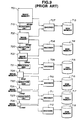
- FIG. 9 An example of conventional hierarchical encoding is shown in FIG. 9.
- an original image to be encoded has a resolution of 400-dpi (dots per inch).
- image memories 701 through 706 are provided for storing 400-, 200-, 100-, 50-, 25- and 12.5-dpi images, respectively.
- Reduction units 719 through 723 provides 200-, 100-, 50-, 25- and 12.5-dpi images, respectively, and encoders 707 through 712 encode 400-, 200-, 100-, 50-, 25- and 12.5-dpi images, respectively.
- the encoded 400-, 200-, 100-, 50-, 25- and 12.5-dpi images are stored in disk memories 713 through 718, respectively.
- Reduction unit 719 reduces a 400-dpi image, from image memory 701, by a technique in which the image is subsampled to 1/2 in both the main-scanning and sub-scanning directions to provide a 200-dpi image, which is stored in image memory 702.
- the above mentioned subsample process is not a simple subsampling as default, but a specially programmed JBIG standard method.
- the 200-dpi image is further reduced by reduction unit 720 to provide a 100-dpi image, which is stored in image memory 703.
- 50-, 25- and 12.5-dpi images are provided and are stored in image memories 704, 705 and 706, respectively.
- the images which are stored in disk memories 713 through 718, are transmitted, in turn, in codes beginning with lower resolution images so as to give a rough overall image. Namely, the images are transmitted in the order of 12.5-, 25-, 50-, 100-, 200- and 400-dpi images.
- the image stored in image memory 706 is scanned and entropy encoding (such as arithmetic encoding) is performed by referring to an object pixel to be encoded and the surrounding pixels.
- encoding is performed by encoder 711 by referring to pixels surrounding a target pixel from image memory 705, and surrounding pixels of the 12.5-dpi image from image memory 706, so that encoding efficiency is improved.
- the 25-dpi image of image memory 705 is referred to and encoded by encoder 710; as regards the 100-dpi image of image memory 703, the 50-dpi image of image memory 704 is referred to and encoded by encoder 709; as regards the 200-dpi image of image memory 702, the 100-dpi image of image memory 703 is referred to and encoded by encoder 708; and, as regards the actual-size (400-dpi) image of image memory 701, the 200-dpi image of image memory 702 is referred to and encoded by encoder 707.
- the present invention has been made in consideration of the above-described problems.
- an image processing apparatus for performing hierarchical resolution encoding of image data, comprising: first storage means operable to store image data; second storage means, which is different from said first storage means, operable to store image data; conversion means operable to convert a resolution of image data; and encoding means operable to encode image data, characterised in that the apparatus is operable such that image data having a first resolution read from said first storage means is encoded by said encoding means to provide first encoded data and the image data having the first resolution is also converted into image data having a second resolution by said conversion means, and that the image data having the second resolution is stored in said second storage means, the image data having the second resolution read from said second storage means is then encoded by said encoding means to provide second encoded data and the image data having the second resolution is also converted into image data having a third resolution by said conversion means, and the image data having the third resolution is stored in said first storage means in which the image data having the first resolution has been stored.
- An advantage of the present invention to provide an image processing apparatus, having a simple configuration, in which the number or the quantity of image memories used in hierarchical encoding and decoding is reduced.
- image data having a first resolution, read from first storage means is encoded by encoding means and is converted into image data having a second resolution by conversion means.
- the image data having the second resolution is stored in second storage means.
- the image data having the second resolution, read from the second storage means is encoded by the encoding means and is converted into image data having a third resolution by the conversion means.
- the image data having the third resolution is also stored in the first storage means in which the image data having the first resolution has been stored.
- an original image is assumed to be a 400-dpi image, which is sequentially reduced by 1/2 to a 12.5-dpi image.
- the resolution of the original image and the number of hierarchies are not limited to the above-described values.
- FIG. 1 illustrates the configuration of an image processing apparatus according to the first embodiment.
- image memories 101 and 107 there are shown image memories 101 and 107, parallel/serial conversion or serial/parallel conversion shift registers 103 and 109, line memories 105 and 111, each comprising a FIFO circuit, image reduction unit 113 for reducing images and for generating reference pixels for arithmetic encoding, arithmetic encoder 114, code buffer memory 115 and data bus 116.
- Image reduction unit 113 performs image reduction processing as disclosed in U.S. Patent No. 5,159,468.
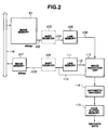
- FIG. 2 illustrates the flow of signals when 400-dpi original-image data is converted into a 200-dpi image, and is encoded.
- the 400-dpi image data is written in image memory 101, which can store image data (corresponding to a 400-dpi image) for at least one sheet having an original image, via a line, such as data bus 116 or the like.
- Image memory 107 stores image data of a reduced 200-dpi image. Accordingly, image memory 107 is only required to have a capacity corresponding to 1/4 of the capacity of image memory 101.
- image data 102 read from the high-resolution image memory 101 in the sequence of raster scanning, is packed as parallel data having a predetermined bit length, it is converted into serial data 104 by shift register 103.
- serial data 104 is input to image reduction unit 113 as pixel data 106, for several lines in the sub-scanning direction, via line memory 105 having a delay amount for the several lines.
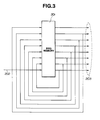
- FIG. 3 shows the method of connection of line memory 105.
- FIFO memory 201 can store image data for at least 8 lines.
- Reference numeral 202 represents input serial image data.
- Reference numeral 203 represents delayed image data for 8 lines.
- serial image data 202 is delayed by 8 lines via FIFO memory 201 shown in FIG. 3, and parallel image data 203 is output.
- pixel data 110 reduced to a 200-dpi image by image reduction unit 113, is subjected to serial/parallel conversion by shift register 109, and is written in image memory 107 as reduced parallel image data 108.
- shift register 109 is unnecessary.
- Image reduction unit 113 supplies arithmetic encoder 114 with image data for several pixels (necessary for encoding) from among 400-dpi image data input from line memory 105 and 200-dpi image data obtained from the 400-dpi image data. Arithmetic encoder 114 performs prediction by making several high-resolution and several low-resolution pixels predictive reference pixels. A target pixel transmitted from image reduction unit 113 is encoded based on the result of the prediction. Encoded data obtained from arithmetic encoder 114 is stored in code buffer memory 115 in a predetermined amount, and is output.
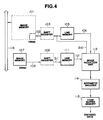
- FIG. 4 illustrates the flow of signals when a 100-dpi image is generated from the 200-dpi image stored in image memory 107, and is encoded.
- reference numeral 310 represents pixel data reduced by image reduction unit 113.
- serial data 311 is input to image reduction unit 113 as pixel data 112, for several lines in the sub-scanning direction, via line memory 111 having a delay amount for the several lines.
- Pixel data 310 reduced to a 100-dpi image by image reduction unit 113, is subjected to serial/parallel conversion by shift register 103, and is written in image memory 101 as parallel image data 102.
- shift register 103 is unnecessary.
- Image reduction unit 113 supplies arithmetic encoder 114 with image data for several pixels, necessary for encoding, from among 200-dpi image data input from line memory 111 and 100-dpi image data obtained from the 200-dpi image data.
- Image memory 101 is an image memory for 400-dpi image data. However, a part of image memory 101 is used as an image memory for 100-dpi image data. The direction of read/write for image memory 101 shown in FIG. 4 is opposite to that of image memory 101 shown in FIG. 2. A 100-dpi reduced image is stored in this image memory 101 in FIG. 4, and the original 400-dpi image data is lost. However, since the 400-dpi image data has been encoded together with the 200-dpi image data and has been stored in code buffer memory 115, or an external memory as encoded data, it can be decoded whenever necessary.
- 12.5-dpi image data is first decoded and stored in image memory 107, followed by the decoding and storage of 25-dpi image data, 50-dpi image data, and 100-dpi image data, in image memories 101, 107, and again in 101, respectively.
- image data of a certain resolution is required for an outputting operation, such as a display operation or the like, the image data may, of course, be sequentially transferred via data bus 116.
- FIG. 5 illustrates the configuration of an image processing apparatus used in decoding.
- image memory 401 for 400-dpi original-image data
- shift registers 403 and 409 line memories 405 and 411
- image memory 407 for 200-dpi reduced image data
- reference-pixel generation unit 413 for arithmetic decoder 414
- code buffer memory 415 for arithmetic decoder
- FIG. 5 illustrates the operation when (400-dpi) image data corresponding to the original image is decoded and stored in image memory 401.
- decoded-pixel data 404 is output from arithmetic decoder 414.
- the decoded-pixel data 404 is stored in image memory 401, and is input to line memory 405 so as to be used as reference-pixel data for decoding the subsequent encoded data.
- reference pixel generation unit 413 Since image reduction processing is unnecessary in decoding, reference pixel generation unit 413 has only the function of generating reference pixels.
- the same configuration may be used in both encoding and decoding operations.
- FIG. 6 illustrates the configuration of an image processing apparatus according to a second embodiment of the present invention.
- image memory 504 for 200-dpi reduced image data there are shown: image memory 504 for 200-dpi reduced image data, shift register 506, line memories 502 and 507, image reduction unit 510, arithmetic encoder 511, code buffer memory 512 and data bus 513.
- FIG. 6 illustrates the flow of signals when 400-dpi image data, obtained by reading an original image by a scanner (not shown), is converted into 200-dpi image data, and is encoded.
- an image scanner which reads an original image line by line using a CCD (charge-coupled device) linear image sensor, is used as a device for inputting the 400-dpi original image.
- an output device such as a laser-beam printer (LBP) or the like, is directly connected.
- LBP laser-beam printer
- serial data output from the image scanner is directly input to line memory 502, to be delayed by several lines, and is then input to image reduction unit 510.
- image reduction unit 510 200-dpi image data (after image reduction) is stored in image memory 504, and encoded data, subject to hierarchical encoding based on 400-dpi and 200-dpi image data supplied from image reduction unit 510, is generated by arithmetic encoder 511 and is stored in code buffer memory 512.
- image memory 601 having a size for a 100-dpi image, and shift register 603, for serial/parallel conversion, is provided.
- 100-dpi image data 610 reduced by image reduction unit 510, is stored in image memory 601 as parallel image data 602 via shift register 603.
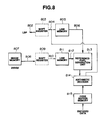
- FIG. 8 illustrates the flow of signals when the above-described encoded data, representing the 400-dpi image subjected to arithmetic encoding, is decoded, and image data obtained by the decoding operation is supplied to the LBP to record the 400-dpi image.
- shift registers 803 and 809 there are shown shift registers 803 and 809, line memories 805 and 811, image memory 807 for 200-dpi reduced image data, reference pixel generation unit 813, arithmetic decoder 814 and code buffer memory 815.
- FIG. 8 illustrates the operation when encoded data from code buffer memory 815 is decoded, and a (400-dpi) image corresponding to the original image is recorded by the LBP.
- the 200-dpi image data stored in image memory 807, and the 400-dpi image data after decoding stored in line memory 805, are supplied to reference pixel generation unit 813.
- Arithmetic decoder 814 decodes the encoded data based on reference-pixel data from reference-pixel generation unit 813, and the serial data output of arithmetic decoder 814 is directly output to the LBP. Accordingly, it is unnecessary to store the 400-dpi image data after decoding.
- image data of the original-image level can be input and output without providing a 400-dpi image memory (requiring a capacity of about 2Mb for the A4 size) which greatly influences the cost.
Landscapes
- Engineering & Computer Science (AREA)
- Multimedia (AREA)
- Signal Processing (AREA)
- Editing Of Facsimile Originals (AREA)
- Compression Of Band Width Or Redundancy In Fax (AREA)
- Storing Facsimile Image Data (AREA)
- Compression Or Coding Systems Of Tv Signals (AREA)
Description
Claims (13)
- An image processing apparatus for performing hierarchical resolution encoding of image data, comprising:characterised in that the apparatus is operable such that image data (102) having a first resolution read from said first storage means is encoded by said encoding means to provide first encoded data and the image data having the first resolution is also converted into image data having a second resolution by said conversion means, and that the image data (108) having the second resolution is stored in said second storage means, the image data having the second resolution read from said second storage means is then encoded by said encoding means to provide second encoded data and the image data having the second resolution is also converted into image data (310) having a third resolution by said conversion means, and the image data having the third resolution is stored in said first storage means in which the image data having the first resolution has been stored.first storage means (101) operable to store image data;second storage means (107), which is different from said first storage means, operable to store image data;conversion means (113) operable to convert a resolution of image data; andencoding means (114) operable to encode image data,
- An image processing apparatus according to claim 1, wherein said conversion means is operable to perform conversion to reduce a resolution of image data.
- An image processing apparatus according to claim 2, wherein said encoding means (114) is operable to encode the image data by prediction by making several high-resolution and several low-resolution pixels of said image data predictive reference pixels.
- An image processing apparatus according to any preceding claim, wherein said encoding means is further operable to encode the image data having the third resolution read from said first storage means.
- An image processing apparatus according to any preceding claim, wherein said conversion means is operable to convert the image data having the third resolution read from said first storage means into image data having a fourth resolution, and the second storage means is operable to store the image data having the fourth resolution.
- An image processing apparatus as claimed in any preceding claim comprising a buffer memory operable to store the first encoded data and the second encoded data.
- An image processing method for performing hierarchical resolution encoding of image data, comprising the steps of:encoding image data (102) having a first resolution read from a first storage means (101) to provide first encoded data;converting the image data having the first resolution into image data having a second resolution;storing the image data (108) having the second resolution in a second storage means (107) which is different from the first storage means;encoding the image data having the second resolution read from the second storage means to provide second encoded data;converting the image data having the second resolution into image data having a third resolution; andstoring the image data (310) having the third resolution in the first storage means in which the image data having the first resolution has been stored.
- An image processing method according to claim 7, wherein said converting step performs conversion to reduce a resolution of image data.
- An image processing method according to claim 7, wherein the image data having the first resolution is encoded by prediction by making pixels of image data subject to resolution conversion in said converting steps predictive reference pixels.
- An image processing method according to any of claims 7 to 9, further comprising the step of encoding the image data having the third resolution read from the first storage means.
- An image processing method according to any of claims 7 to 10, further comprising the step of converting the image data having the third resolution read from the first storage means into image data having a fourth resolution.
- An image processing method according to claim 11, further comprising the step of storing the image data having the fourth resolution in the second storage means in which the image data having the second resolution has been stored.
- An image processing method as claimed in any of claims 7 to 12 including the step of storing the first encoded data and the second encoded data in a buffer memory.
Applications Claiming Priority (2)
| Application Number | Priority Date | Filing Date | Title |
|---|---|---|---|
| JP303861/92 | 1992-11-13 | ||
| JP30386192 | 1992-11-13 |
Publications (2)
| Publication Number | Publication Date |
|---|---|
| EP0597698A1 EP0597698A1 (en) | 1994-05-18 |
| EP0597698B1 true EP0597698B1 (en) | 1998-08-05 |
Family
ID=17926173
Family Applications (1)
| Application Number | Title | Priority Date | Filing Date |
|---|---|---|---|
| EP93308988A Expired - Lifetime EP0597698B1 (en) | 1992-11-13 | 1993-11-10 | Image processing apparatus and method therefore |
Country Status (3)
| Country | Link |
|---|---|
| US (1) | US5579412A (en) |
| EP (1) | EP0597698B1 (en) |
| DE (1) | DE69320146T2 (en) |
Families Citing this family (12)
| Publication number | Priority date | Publication date | Assignee | Title |
|---|---|---|---|---|
| US5832112A (en) * | 1993-12-24 | 1998-11-03 | Canon Kabushiki Kaisha | Image processing apparatus capable of detecting specific originals |
| JPH08214201A (en) * | 1994-11-28 | 1996-08-20 | Canon Inc | Image pickup device |
| US6873738B2 (en) * | 1995-10-02 | 2005-03-29 | Sony Corporation | Hierarchical image processor for encoding or decoding, and memory on the same chip |
| JPH1093827A (en) * | 1996-09-11 | 1998-04-10 | Canon Inc | Image processing unit and its device |
| US6091860A (en) * | 1997-11-12 | 2000-07-18 | Pagemasters, Inc. | System and method for processing pixels for displaying and storing |
| AU4701999A (en) * | 1998-06-19 | 2000-01-05 | Equator Technologies, Inc. | Decoding an encoded image having a first resolution directly into a decoded image having a second resolution |
| US6763150B1 (en) * | 2000-08-29 | 2004-07-13 | Freescale Semiconductor, Inc. | Image processing system with multiple processing units |
| JP2004173069A (en) * | 2002-11-21 | 2004-06-17 | Canon Inc | Image data recorder and recording method |
| US20050232355A1 (en) * | 2004-04-15 | 2005-10-20 | Srinivas Cheedela | Video decoder for supporting both single and four motion vector macroblocks |
| JP2007067917A (en) * | 2005-08-31 | 2007-03-15 | Matsushita Electric Ind Co Ltd | Image data processing apparatus |
| US20070052982A1 (en) * | 2005-09-07 | 2007-03-08 | Kabushiki Kaisha Toshiba | Color image forming apparatus and image forming method |
| KR100759224B1 (en) * | 2005-12-14 | 2007-09-17 | 주식회사 대우일렉트로닉스 | Method for displaying video of display apparatus |
Family Cites Families (5)
| Publication number | Priority date | Publication date | Assignee | Title |
|---|---|---|---|---|
| US4742558A (en) * | 1984-02-14 | 1988-05-03 | Nippon Telegraph & Telephone Public Corporation | Image information retrieval/display apparatus |
| US4903317A (en) * | 1986-06-24 | 1990-02-20 | Kabushiki Kaisha Toshiba | Image processing apparatus |
| DE68928397T2 (en) * | 1988-08-30 | 1998-03-19 | Canon Kk | Image coding process |
| JPH02177766A (en) * | 1988-12-28 | 1990-07-10 | Canon Inc | Hierarchical encoding system for binary image |
| US5231679A (en) * | 1989-09-01 | 1993-07-27 | Sanyo Electric Co., Ltd. | Image processing apparatus and image reducing circuit therefor |
-
1993
- 1993-11-10 DE DE69320146T patent/DE69320146T2/en not_active Expired - Fee Related
- 1993-11-10 EP EP93308988A patent/EP0597698B1/en not_active Expired - Lifetime
-
1995
- 1995-05-17 US US08/443,387 patent/US5579412A/en not_active Expired - Fee Related
Also Published As
| Publication number | Publication date |
|---|---|
| EP0597698A1 (en) | 1994-05-18 |
| DE69320146D1 (en) | 1998-09-10 |
| DE69320146T2 (en) | 1999-05-20 |
| US5579412A (en) | 1996-11-26 |
Similar Documents
| Publication | Publication Date | Title |
|---|---|---|
| EP0564227B1 (en) | Image encoding apparatus and method | |
| US5267052A (en) | Encoding the original image data and progessively encoding the image data independently | |
| EP0597698B1 (en) | Image processing apparatus and method therefore | |
| CA2013232C (en) | Image reduction system | |
| US4688100A (en) | Video data encoding/decoding apparatus | |
| US4796092A (en) | Image processing with compression encoding | |
| US5271072A (en) | Image reduction of binary images using filtering processing | |
| US4071855A (en) | Encoder and decoder for bandwidth compression | |
| US8126295B2 (en) | Image processing apparatus and method of using the same | |
| JPH07264417A (en) | Image coding method | |
| US4682241A (en) | Data transfer system | |
| FI79218C (en) | FOERFARANDE FOER MELLANLAGRING AV FAKSIMILDATA. | |
| US20020033971A1 (en) | Image input device | |
| JP3230551B2 (en) | Image processing apparatus and method | |
| US5673119A (en) | Encoding processing apparatus | |
| JP2830639B2 (en) | Predictive coding device | |
| CA1129073A (en) | Sub-sampling and interpolation techniques for (facsimile) graphic signals | |
| JP3247754B2 (en) | Image transmission device | |
| JPS61256863A (en) | Facsimile method | |
| KR960016839B1 (en) | Reading and recording apparatus of facsimile | |
| JP2712426B2 (en) | Image transmission device | |
| JPH08102846A (en) | Line density conversion enabled picture processor | |
| JPS5815370A (en) | Transmission system for digital facsimile signal including intermediate image gradation | |
| JPS58136172A (en) | Facsimile code transmission method | |
| JPS6065670A (en) | Picture information transmitting system |
Legal Events
| Date | Code | Title | Description |
|---|---|---|---|
| PUAI | Public reference made under article 153(3) epc to a published international application that has entered the european phase |
Free format text: ORIGINAL CODE: 0009012 |
|
| AK | Designated contracting states |
Kind code of ref document: A1 Designated state(s): DE FR GB |
|
| 17P | Request for examination filed |
Effective date: 19940930 |
|
| 17Q | First examination report despatched |
Effective date: 19970207 |
|
| GRAG | Despatch of communication of intention to grant |
Free format text: ORIGINAL CODE: EPIDOS AGRA |
|
| RTI1 | Title (correction) | ||
| GRAG | Despatch of communication of intention to grant |
Free format text: ORIGINAL CODE: EPIDOS AGRA |
|
| GRAG | Despatch of communication of intention to grant |
Free format text: ORIGINAL CODE: EPIDOS AGRA |
|
| GRAH | Despatch of communication of intention to grant a patent |
Free format text: ORIGINAL CODE: EPIDOS IGRA |
|
| GRAH | Despatch of communication of intention to grant a patent |
Free format text: ORIGINAL CODE: EPIDOS IGRA |
|
| GRAA | (expected) grant |
Free format text: ORIGINAL CODE: 0009210 |
|
| AK | Designated contracting states |
Kind code of ref document: B1 Designated state(s): DE FR GB |
|
| REF | Corresponds to: |
Ref document number: 69320146 Country of ref document: DE Date of ref document: 19980910 |
|
| ET | Fr: translation filed | ||
| PLBE | No opposition filed within time limit |
Free format text: ORIGINAL CODE: 0009261 |
|
| STAA | Information on the status of an ep patent application or granted ep patent |
Free format text: STATUS: NO OPPOSITION FILED WITHIN TIME LIMIT |
|
| 26N | No opposition filed | ||
| REG | Reference to a national code |
Ref country code: GB Ref legal event code: IF02 |
|
| PGFP | Annual fee paid to national office [announced via postgrant information from national office to epo] |
Ref country code: GB Payment date: 20031027 Year of fee payment: 11 |
|
| PGFP | Annual fee paid to national office [announced via postgrant information from national office to epo] |
Ref country code: FR Payment date: 20031125 Year of fee payment: 11 |
|
| PGFP | Annual fee paid to national office [announced via postgrant information from national office to epo] |
Ref country code: DE Payment date: 20031126 Year of fee payment: 11 |
|
| PG25 | Lapsed in a contracting state [announced via postgrant information from national office to epo] |
Ref country code: GB Free format text: LAPSE BECAUSE OF NON-PAYMENT OF DUE FEES Effective date: 20041110 |
|
| PG25 | Lapsed in a contracting state [announced via postgrant information from national office to epo] |
Ref country code: DE Free format text: LAPSE BECAUSE OF NON-PAYMENT OF DUE FEES Effective date: 20050601 |
|
| GBPC | Gb: european patent ceased through non-payment of renewal fee |
Effective date: 20041110 |
|
| PG25 | Lapsed in a contracting state [announced via postgrant information from national office to epo] |
Ref country code: FR Free format text: LAPSE BECAUSE OF NON-PAYMENT OF DUE FEES Effective date: 20050729 |
|
| REG | Reference to a national code |
Ref country code: FR Ref legal event code: ST |