EP0596566B1 - High-voltage transformer - Google Patents
High-voltage transformer Download PDFInfo
- Publication number
- EP0596566B1 EP0596566B1 EP93203018A EP93203018A EP0596566B1 EP 0596566 B1 EP0596566 B1 EP 0596566B1 EP 93203018 A EP93203018 A EP 93203018A EP 93203018 A EP93203018 A EP 93203018A EP 0596566 B1 EP0596566 B1 EP 0596566B1
- Authority
- EP
- European Patent Office
- Prior art keywords
- current
- bushing
- voltage transformer
- zone
- bushings
- Prior art date
- Legal status (The legal status is an assumption and is not a legal conclusion. Google has not performed a legal analysis and makes no representation as to the accuracy of the status listed.)
- Expired - Lifetime
Links
Images

Classifications
-
- H—ELECTRICITY
- H02—GENERATION; CONVERSION OR DISTRIBUTION OF ELECTRIC POWER
- H02H—EMERGENCY PROTECTIVE CIRCUIT ARRANGEMENTS
- H02H1/00—Details of emergency protective circuit arrangements
- H02H1/0007—Details of emergency protective circuit arrangements concerning the detecting means
-
- G—PHYSICS
- G01—MEASURING; TESTING
- G01R—MEASURING ELECTRIC VARIABLES; MEASURING MAGNETIC VARIABLES
- G01R15/00—Details of measuring arrangements of the types provided for in groups G01R17/00 - G01R29/00, G01R33/00 - G01R33/26 or G01R35/00
- G01R15/14—Adaptations providing voltage or current isolation, e.g. for high-voltage or high-current networks
- G01R15/24—Adaptations providing voltage or current isolation, e.g. for high-voltage or high-current networks using light-modulating devices
-
- H—ELECTRICITY
- H02—GENERATION; CONVERSION OR DISTRIBUTION OF ELECTRIC POWER
- H02H—EMERGENCY PROTECTIVE CIRCUIT ARRANGEMENTS
- H02H1/00—Details of emergency protective circuit arrangements
- H02H1/0061—Details of emergency protective circuit arrangements concerning transmission of signals
- H02H1/0069—Details of emergency protective circuit arrangements concerning transmission of signals by means of light or heat rays
-
- H—ELECTRICITY
- H02—GENERATION; CONVERSION OR DISTRIBUTION OF ELECTRIC POWER
- H02H—EMERGENCY PROTECTIVE CIRCUIT ARRANGEMENTS
- H02H7/00—Emergency protective circuit arrangements specially adapted for specific types of electric machines or apparatus or for sectionalised protection of cable or line systems, and effecting automatic switching in the event of an undesired change from normal working conditions
- H02H7/04—Emergency protective circuit arrangements specially adapted for specific types of electric machines or apparatus or for sectionalised protection of cable or line systems, and effecting automatic switching in the event of an undesired change from normal working conditions for transformers
-
- H—ELECTRICITY
- H02—GENERATION; CONVERSION OR DISTRIBUTION OF ELECTRIC POWER
- H02H—EMERGENCY PROTECTIVE CIRCUIT ARRANGEMENTS
- H02H9/00—Emergency protective circuit arrangements for limiting excess current or voltage without disconnection
- H02H9/04—Emergency protective circuit arrangements for limiting excess current or voltage without disconnection responsive to excess voltage
Definitions
- the invention relates to a high-voltage transformer.
- a high-voltage transformer is known from Asea magazine 1980, pages 3 to 10, the primary and secondary winding connections of which are each led through bushings to external connection points. It is also known (DE-GM 75 22 858) to provide measuring means for determining the primary and secondary current levels, which are assigned to an evaluation device such that if the ratio of the current levels does not correspond to the reciprocal of the transformation ratio of the transformer, the deviation for triggering circuit breakers upstream of the transformer are used on the primary and secondary sides.
- current transformers are provided, each of which measures the primary or secondary current, and an evaluation device, which triggers circuit breakers in the primary or secondary current circuit from the difference in their output signals.
- the measuring means for determining the primary-side and secondary-side current strength as a ring current transformer which is arranged between the bushings and the transformer windings.
- This design allows a simple measuring arrangement, but has the disadvantage that disturbances in the current profile that occur in the area of the bushings are not detected by the transducers, so that it can lead to destruction of the transformer, since the area of the bushings is not in the surveillance area of the security devices is included.
- the invention is based on the object of further developing a high-voltage transformer in such a way that its construction is improved in terms of cost and safety. This object is achieved by the features of claim 1.
- the invention is characterized in that the design of the means for determining the current strengths as electro-optical current sensors makes it possible to arrange them as an integrated structural unit within a respective implementation. This enables the area of the bushings to be monitored with regard to the current, so that the safety devices are also triggered by errors occurring there.
- the space-saving arrangement of the electro-optical current sensors is used.
- these sensors are suitable for current monitoring because they are galvanically decoupled due to the use of optical fibers and interference by electromagnetic fields is avoided. This is a considerable advantage over conventional current transformers, particularly in the case of extra-high voltage transformers.
- the lead-out point of the current signal can be predetermined virtually arbitrarily, since the transformer currents do not have any undesired influences on the measurement signal.
- the light guides of each current sensor are guided within the assigned bushing in the area between bushing and the associated winding connection.
- it is provided to lead the light guide out of the bushing in the vicinity of the bushing flange.
- the current sensors are each assigned further electro-optical converters as voltage sensors.
- a voltage measurement can also take place, which also has the advantage that it can take place unaffected by interference caused by the maximum voltage of the transformer.
- the invention relates to a high-voltage transformer of the type mentioned at the outset, which additionally has surge arresters connected between the regions of the bushings adjacent to the outer connection points and ground potential.
- the invention additionally provides that the area of the bushing adjacent to the outer connection point is surrounded by a housing which has an insulating inlet opening for the current conductor leading into the bushing (4) , wherein the surge arrester (18) is conductively connected to the housing jacket and the housing jacket to an intermediate Current sensor and bushing is conductively connected to the conductor.
- a solution equivalent to this provides that the area of the bushing adjacent to the outer connection point is surrounded by a housing which has an inlet opening conductively connected to the housing jacket for the current conductor leading into the bushing, the surge arrester being guided through an insulating bushing in the housing jacket is and is conductively connected to the conductor at a point between the current sensor and the bushing.
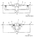
- the high-voltage transformer essentially consists of its primary winding 2, its secondary winding 3 and bushings 4, 5 each assigned to a winding, with a respective outer connection point 6, 7, via which the currents from the transformer 1 are transmitted to the switchgear.
- circuit breakers 8, 9 are provided both on the primary side and on the secondary side, which are triggered by a measuring device shown below if the ratio of current strengths does not correspond to the reciprocal of the transformation ratio of the transformer.
- the currents from the primary or secondary side are detected via conventional current transformers 10, 11, the output signals of which are fed into an evaluation device 12, which forms a difference signal from the two input signals. If, taking into account the transformation ratio of the high-voltage transformer 1, the currents in the secondary or primary side deviate from one another, the evaluation device 12 sends a signal to the circuit breakers 8, 9 so that they switch off immediately and protect the high-voltage transformer from further current supply.
- the embodiment shown in FIG. 2 differs from the first in that the current transformers are not arranged outside the outer connection points 6, 7 as in FIG. 1, but in the transformer between the respective winding and the associated implementation, so are arranged in the so-called dome of the transformer.
- the embodiment according to FIG. 2 differs from that according to FIG. 1 in that, in the arrangement of the current transformers within the transformer, only those currents which occur directly in the winding area can be detected, while currents in the area of the bushings are not detected .
- FIG. 3 corresponds to the illustrated FIGS. 1 and 2 with respect to the corresponding reference numerals.
- the current transformers are designed as electro-optical current sensors 10, 11 which are arranged in the area of the bushings 4, 5 adjacent to the outer connection points 6, 7.
- the output signals of the current sensors 10, 11 are transmitted by means of light guides 14, 15 which, starting from the current sensors 10, 11 are laid within the respective bushings 4, 5 and lead into the associated dome areas 16, 17, each between bushing 4, 5 and associated high-voltage winding 2,3 are arranged.
- the respective current signal is transmitted from the dome area 16, 17 to the evaluation device 12 via the light guide.
- the light guide from the implementation near the Lead out through flange.
- electro-optical current sensors utilize the Faraday effect, according to which, in certain light-conducting materials, the plane of polarization of a linearly polarized light beam is rotated about an axis which runs parallel to the light beam under the influence of a magnetic field which extends along the light beam.
- the extent of the rotation of the polarization plane is proportional to the size of the magnetic field, which in turn is proportional to the electric current.
- the arrangement according to the invention of the electro-optical current sensors in the edge region of the bushings can also be used to monitor faults which, according to the exemplary embodiment shown in FIG. 2, would have resulted in consequential damage in the event of an internal fault in the high-voltage transformer and its bushings.
- the sensor unit formed by the electro-optical converter and the light guide can be easily retrofitted to existing high-voltage transformers, the connection points in the respective domes for leading the measurement signal into the evaluation device 12, which are already present in the high-voltage transformer known from the prior art, can be used .
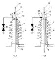
- FIGS. 4 and 5 show a detail from FIG. 3 in the area of bushing 4 shown there on the left, or its head, in which current sensor 10 is accommodated.
- the "cathedral" 16 is only indicated in the figures 4 and 5.
- a housing 19 in the area surrounding the current transformer 10 on the lead-through head there is a housing 19, the casing of which is in the upper area, ie in the area in which a current conductor 20 is led from the outer connection points into the lead-through 4. is designed to be insulating.
- the surge arrester 18 is conductively connected to the housing jacket. Between the housing jacket and the current conductor 20 there is a conductive connection 23 which is positioned at a location which lies between the position of the current transformer 10 and the start of the feedthrough 4.
- FIG. 5 A configuration equivalent to this is shown in FIG. 5.
- the inlet opening of the housing jacket is not, as in FIG. 4, insulated from the current conductor 20, but rather is conductive with the latter connected.
- the connection point of the surge arrester 18, however, is guided through an insulating bushing 24 through the housing jacket and, in turn, is conductively contacted with the conductor 20 at a point which lies between the current transformer 10 and the start of the bushing 4. This also ensures that the current flowing into the surge arrester 18 is detected by the current transformer 10.
Abstract
Description
Die Erfindung betrifft einen Hochspannungstransformator.The invention relates to a high-voltage transformer.
Aus der Asea-Zeitschrift 1980, Seite 3 bis 10 ist ein Hochspannungstransformator bekannt, dessen Primär- und Sekundärwicklungsanschlüsse jeweils über Durchführungen an äußere Anschlußpunkte geführt sind. Ebenso ist es bekannt (DE-GM 75 22 858), Meßmittel zur Bestimmung der primärseitigen und sekundärseitigen Stromstärke vorzusehen, die einer Auswerteeinrichung derart zugeordnet sind, daß, wenn das Verhältnis der Stromstärken nicht dem Kehrwert des Übersetzungsverhältnisses des Transformators entspricht, die Abweichung zur Auslösung von dem Transformator primär- und sekundärseitig vorgeordneten Leistungsschaltern herangezogen wird.A high-voltage transformer is known from Asea magazine 1980,
Zur Vermeidung von Folgeschäden ist bei Hochspannungstransformatoren bei einem inneren Fehler eine Schnellabschaltung erforderlich.In order to avoid consequential damage, high-speed transformers require a quick shutdown in the event of an internal fault.
Hierzu sind Stromwandler vorgesehen, die jeweils den Primär- bzw. Sekundärstrom messen, sowie eine Auswerteeinrichtung, die aus der Differenz ihrer Ausgangssignale eine Auslösung von Leistungsschaltern im Primär- bzw. Sekundärstromkreislauf bewirkt.For this purpose, current transformers are provided, each of which measures the primary or secondary current, and an evaluation device, which triggers circuit breakers in the primary or secondary current circuit from the difference in their output signals.
In einer ersten Variante ist dabei im Stand der Technik vorgesehen, herkömmliche Stromwandler in der Schaltanlage vorzusehen, die außerhalb des Hochspannungstransformators angeordnet sind.In a first variant, it is provided in the prior art to provide conventional current transformers in the switchgear assembly, which are arranged outside the high-voltage transformer.
Solche herkömmliche Stromwandler weisen den Nachteil auf, daß sie einen erheblichen Platzbedarf in der Schaltanlage benötigen und ein zusätzliches Gefahrenprotential darstellen. Desweiteren ist hierfür ein hoher Investitionsaufwand erforderlich.Such conventional current transformers have the disadvantage that they require a considerable amount of space in the switchgear and represent an additional hazard potential. Furthermore, a high investment is required for this.
In einer anderen Variante ist es aus dem Stand der Technik bekannt, die Meßmittel zur Bestimmung der primärseitigen und sekundärseitigen Stromstärke als Ringstromwandler auszuführen, welcher zwischen den Durchführungen und den Transformatorwicklungen angeordnet ist. Diese Ausführung erlaubt eine einfache meßtechnische Anordnung, hat aber den Nachteil, daß Störungen im Stromverlauf, die im Bereich der Durchführungen erfolgen, von den Wandlern nicht erfaßt werden, so daß es hierdurch zu Zerstörungen des Transformators kommen kann, da der Bereich der Durchführungen nicht in den Überwachungsbereich der Sicherungseinrichtungen miteinbezogen ist.In another variant, it is known from the prior art to design the measuring means for determining the primary-side and secondary-side current strength as a ring current transformer which is arranged between the bushings and the transformer windings. This design allows a simple measuring arrangement, but has the disadvantage that disturbances in the current profile that occur in the area of the bushings are not detected by the transducers, so that it can lead to destruction of the transformer, since the area of the bushings is not in the surveillance area of the security devices is included.
Aus der DE-OS 3431769 ist es bekannt, einen faseroptischen Stromsensor für Schutzzwecke vorzusehen, welcher aus Lichtleitfasern besteht, die in der Nähe einer stromführenden Hochspannungsleitung angeordnet sind.From DE-OS 3431769 it is known to provide a fiber optic current sensor for protection purposes, which consists of optical fibers which are arranged in the vicinity of a current-carrying high-voltage line.
Der Erfindung liegt die Aufgabe zugrunde, einen Hochspannungstransformator dahingehend weiterzuentwickeln, daß sein Aufbau kostengünstiger und hinsichtlich der Sicherheit verbessert wird. Diese Aufgabe wird erfindungsgemäß durch die Merkmale des Anspruchs 1 gelöst.The invention is based on the object of further developing a high-voltage transformer in such a way that its construction is improved in terms of cost and safety. This object is achieved by the features of
Die Erfindung zeichnet sich dadurch aus, daß es durch die Ausgestaltung der Mittel zur Bestimmung der Stromstärken als elektrooptische Stromsensoren möglich ist, diese innerhalb einer jeweiligen Durchführung als integrierte Baueinheit anzuordnen. Hierdurch wird ermöglicht, daß auch der Bereich der Durchführungen hinsichtlich des Stromes überwacht wird, so daß auch durch dort auftretende Fehler die Sicherungseinrichtungen ausgelöst werden. Hierbei wird die raumsparende Anordnung der elektrooptischen Stromsensoren ausgenutzt. Insbesondere sind diese Sensoren für die Stromüberwachung geeignet, da sie wegen der Verwendung von Lichtleitern galvanisch entkoppelt sind und Einstreuungen durch elektromagnetische Felder vermieden werden. Dies ist insbesondere bei Höchstspannungstransformatoren ein erheblicher Vorteil gegenüber herkömmlichen Stromwandlern. Andererseits kann durch die Übertragung des Ausgangssignals der elektrooptischen Stromsensoren über Lichtleiter der Herausführungspunkt des Stromsignals praktisch beliebig vorgegeben werden, da ungewollte Beeinflussungen des Meßsignals durch die Transformatorströme nicht stattfinden.The invention is characterized in that the design of the means for determining the current strengths as electro-optical current sensors makes it possible to arrange them as an integrated structural unit within a respective implementation. This enables the area of the bushings to be monitored with regard to the current, so that the safety devices are also triggered by errors occurring there. Here, the space-saving arrangement of the electro-optical current sensors is used. In particular, these sensors are suitable for current monitoring because they are galvanically decoupled due to the use of optical fibers and interference by electromagnetic fields is avoided. This is a considerable advantage over conventional current transformers, particularly in the case of extra-high voltage transformers. On the other hand, by transmitting the output signal of the electro-optical current sensors via optical fibers, the lead-out point of the current signal can be predetermined virtually arbitrarily, since the transformer currents do not have any undesired influences on the measurement signal.
In einer bevorzugten Ausführungsform der Erfindung ist vorgesehen, daß die Lichtleiter jedes Stromsensors innerhalb der zugeordneten Durchführung in den Bereich zwischen Durchführung und dem zugehörigen Wicklungsanschluß geführt sind. Insbesondere ist vorgesehen, den Lichtleiter aus der Durchführung in der Nähe des Durchführungsflansches herauszuleiten. Hierdurch läßt sich eine zweckmäßige und störungsfreie Möglichkeit schaffen, die Auswerteeeinrichtung anzuschließen. Die der Auswerteeinrichtung nachgeordneten Elemente können gegenüber der bisherigen Lösung unverändert bleiben.In a preferred embodiment of the invention it is provided that the light guides of each current sensor are guided within the assigned bushing in the area between bushing and the associated winding connection. In particular, it is provided to lead the light guide out of the bushing in the vicinity of the bushing flange. In this way, an expedient and trouble-free possibility can be created to connect the evaluation device. The elements downstream of the evaluation device can remain unchanged compared to the previous solution.
In einer weiteren Ausgestaltung der Erfindung ist vorgesehen, daß den Stromsensoren jeweils weitere elektrooptische Wandler als Spannungssensoren zugeordnet sind. Neben der Strommessung kann somit auch eine Spannungsmessung erfolgen, die ebenfalls den Vorteil hat, daß sie unbeeinflußt von durch die Höchstspannung des Transformators hervorgerufenen Störungen ablaufen kann.In a further embodiment of the invention, it is provided that the current sensors are each assigned further electro-optical converters as voltage sensors. In addition to the current measurement, a voltage measurement can also take place, which also has the advantage that it can take place unaffected by interference caused by the maximum voltage of the transformer.
Die Erfindung betrifft als weitere bevorzugte Ausführungsform einen Hochspannungstransformator der eingangs genannten Art, welcher zusätzlich jeweils zwischen den den äußeren Anschlußpunkten benachbarten Bereichen der Durchführungen und Erdpotential geschaltete Überspannungsableiter aufweist. Um auch eventuelle an dem Überspannungsableitern auftretende Fehler mit in den Überwachungsprozeß einzubeziehen, sieht die Erfindung zusätzlich vor, daß der dem äußeren Anschlußpunkt benachbarte Bereich der Durchführung von einem Gehäuse umgeben ist, welches eine isolierende Eintrittsöffnung für den in die Durchführung (4) führenden Stromleiter aufweist, wobei der Überspannungsableiter (18) leitend mit dem Gehäusemantel verbunden und der Gehäusemantel an einer zwischen Stromsensor und Durchführung liegenden Stelle leitend mit dem Stromleiter verbunden ist.As a further preferred embodiment, the invention relates to a high-voltage transformer of the type mentioned at the outset, which additionally has surge arresters connected between the regions of the bushings adjacent to the outer connection points and ground potential. In order to also include any faults occurring on the surge arresters in the monitoring process, the invention additionally provides that the area of the bushing adjacent to the outer connection point is surrounded by a housing which has an insulating inlet opening for the current conductor leading into the bushing (4) , wherein the surge arrester (18) is conductively connected to the housing jacket and the housing jacket to an intermediate Current sensor and bushing is conductively connected to the conductor.
Auf diese Weise wird ein Strom, der von den äußeren Anschlußpunkten kommt und über den Überspannungsleiter abfließt, vom Sensor mit erfaßt.In this way, a current that comes from the outer connection points and flows off via the surge conductor is also detected by the sensor.
Eine hierzu äquivalente Lösung sieht vor, daß der dem äußeren Anschlußpunkt benachbarte Bereich der Durchführung von einem Gehäuse umgeben ist, welches eine leitend mit dem Gehäusemantel verbundene Eintrittsöffnung für den in die Durchführung führenden Stromleiter aufweist, wobei der Überspannungsableiter durch eine isolierende Durchführung im Gehäusemantel hindurch geführt ist und an einer zwischen Stromsensor und Durchführung liegenden Stelle leitend mit dem Stromleiter verbunden ist.A solution equivalent to this provides that the area of the bushing adjacent to the outer connection point is surrounded by a housing which has an inlet opening conductively connected to the housing jacket for the current conductor leading into the bushing, the surge arrester being guided through an insulating bushing in the housing jacket is and is conductively connected to the conductor at a point between the current sensor and the bushing.
Die Erfindung wird nun anhand einer Zeichnung näher erläutert:The invention will now be explained in more detail with reference to a drawing:
Hierbei zeigen:
- Fig. 1
- ein Blockschaltbild einer ersten, aus dem Stand der Technik bekannten Ausführungsform eines Hochspannungstransformators,
- Fig. 2
- ein zweites Ausführungsbeispiel eines aus dem Stand der Technik bekannten Hochspannungstransformators und
- Fig. 3
- ein Blockschaltbild des erfindungsgemäßen Hochspannungstransformators.
- Fig. 4
- einen Ausschnitt aus Fig. 3,
- Fig. 5
- eine Alternative zu der Lösung nach Fig. 4.
- Fig. 1
- 2 shows a block diagram of a first embodiment of a high-voltage transformer known from the prior art,
- Fig. 2
- a second embodiment of a high-voltage transformer known from the prior art and
- Fig. 3
- a block diagram of the high voltage transformer according to the invention.
- Fig. 4
- 3 shows a detail from FIG. 3,
- Fig. 5
- an alternative to the solution according to FIG. 4.
Bezugnehmend auf Fig. 1 besteht der Hochspannungstransformator im wesentlichen aus seiner Primärwicklung 2, seiner Sekundärwicklung 3 und jeweils einer Wicklung zugeordneten Durchführungen 4,5, mit einem jeweiligen äußeren Anschlußpunkt 6,7, über den die Ströme vom Transformator 1 in die Schaltanlage übertragen werden.1, the high-voltage transformer essentially consists of its
Außerhalb der äußeren Anschlußpunkte sind sowohl primärseitig als auch sekundärseitig Leistungsschalter 8,9 vorgesehen, die von einer im folgenden dargestellten Meßeinrichtung ausgelöst werden, wenn das Verhältnis Stromstärken nicht dem Kehrwert des Übersetzungsverhältnisses des Transformators entspricht.Outside the outer connection points,
Die Erfassung der Ströme aus der Primär- bzw. Sekundärseite erfolgt nach dem Ausführungsbeispiel aus Fig. 1 über herkömmliche Stromwandler 10,11, deren Ausgangssignale jeweils in eine Auswerteeinrichtung 12 eingespeist werden, welche aus beiden Eingangssignalen ein Differenzsignal bildet. Weichen unter Berücksichtigung des Übersetzungsverhältnisses des Hochspannungstransformators 1 die Stromstärken in Sekundär- bzw. Primärseite voneinander ab, gibt die Auswerteeinrichtung 12 ein Signal an die Leistungsschalter 8,9, so daß diese sofort abschalten und den Hochspannungstransformator vor weiterer Stromzuführung schützen.According to the exemplary embodiment from FIG. 1, the currents from the primary or secondary side are detected via conventional
Das in Fig. 2 dargestellte Ausführungsbeispiel unterscheidet sich von dem ersten dadurch, daß die Stromwandler nicht wie in Fig. 1 außerhalb der äußeren Anschlußpunkte 6,7 angeordnet sind, sondern im Transformator zwischen der jeweiligen Wicklung und der zugehörigen Durchführung, also im sogenannten Dom des Transformators angeordnet sind.The embodiment shown in FIG. 2 differs from the first in that the current transformers are not arranged outside the
Darüber hinaus sind gemäß Fig. 2 keine getrennten herkömmlichen Stromwandler vorgesehen sondern Ringstromwandler.In addition, according to FIG. 2, no separate conventional current transformers are provided, but ring current transformers.
Hinsichtlich der Funktion unterscheidet sich die Ausführung nach Fig. 2 von derjenigen nach Fig. 1 dadurch, daß bei der Anordnung der Stromwandler innerhalb des Transformators nur diejenigen Ströme erfaßt werden können, die unmittelbar im Wicklungsbereich auftreten, während Ströme im Bereich der Durchführungen nicht erfaßt werden.With regard to the function, the embodiment according to FIG. 2 differs from that according to FIG. 1 in that, in the arrangement of the current transformers within the transformer, only those currents which occur directly in the winding area can be detected, while currents in the area of the bushings are not detected .
Das in Fig. 3 dargestellte Ausführungsbeispiel der erfindungsgemäßen Vorrichtung entspricht im Bezug auf die übereinstimmenden Bezugszeichen den dargestellten Figuren 1 und 2.The embodiment of the device according to the invention shown in FIG. 3 corresponds to the illustrated FIGS. 1 and 2 with respect to the corresponding reference numerals.
Im Unterschied zum Stand der Technik ist bei der erfindungsgemäßen Anordnung jedoch vorgesehen, daß die Stromwandler als elektrooptische Stromsensoren 10,11 ausgeführt sind, die in dem den äußeren Anschlußpunkten 6,7 benachbarten Bereich der Durchführungen 4,5, angeordnet sind. Die Ausgangssignale der Stromsensoren 10,11 werden mittels Lichtleitern 14,15 übertragen, welche von den Stromsensoren 10,11 ausgehend innerhalb der jeweiligen Durchführungen 4,5 verlegt sind und in die zugehörigen Dom-Bereiche 16,17 führen, die jeweils zwischen Durchführung 4,5 und zugeordneter Hochspannungswicklung 2,3 angeordnet sind. Aus dem Dom-Bereich 16,17 wird das jeweilige Stromsignal über den Lichtleiter auf die Auswerteeinrichtung 12 übertragen. Alternativ ist vorgesehen, den Lichtleiter aus der Durchführung in der Nähe des Durchführungsflansches herauszuleiten.In contrast to the prior art, it is provided in the arrangement according to the invention that the current transformers are designed as electro-
Die Funktion der elektrooptischen Stromsensoren ist im Prinzip aus der DE-OS 3431769 bekannt. Solche Stromsensoren nutzen den Faraday-Effekt aus, gemäß dem in bestimmten lichtleitenden Materialien die Polarisationsebene eines linearpolarisierten Lichtstrahls unter dem Einfluß eines Magnetfeldes, welches sich entlang des Lichtstrahles erstreckt, um eine Achse gedreht wird, die parallel zum Lichtstrahl verläuft. Das Ausmaß der Drehung der Polarisationsebene ist dabei proportional zur Größe des magnetischen Feldes, welches wiederum proportional zur elektrischen Stromstärke ist.The function of the electro-optical current sensors is known in principle from DE-OS 3431769. Such current sensors utilize the Faraday effect, according to which, in certain light-conducting materials, the plane of polarization of a linearly polarized light beam is rotated about an axis which runs parallel to the light beam under the influence of a magnetic field which extends along the light beam. The extent of the rotation of the polarization plane is proportional to the size of the magnetic field, which in turn is proportional to the electric current.
Durch die erfindungsgemäße Anordnung der elektrooptischen Stromsensoren im Randbereich der Durchführungen lassen sich auch solche Störungen mit überwachen, die nach dem in Fig. 2 dargestellten Ausführungsbeispiel zu von Folgeschäden bei einem inneren Fehler des Hochspannungstransformators sowie seiner Durchführungen geführt hätten.The arrangement according to the invention of the electro-optical current sensors in the edge region of the bushings can also be used to monitor faults which, according to the exemplary embodiment shown in FIG. 2, would have resulted in consequential damage in the event of an internal fault in the high-voltage transformer and its bushings.
Die Sensoreinheit gebildet durch den elektrooptischen Wandler und den Lichtleiter läßt sich an bestehenden Hochspannungstransformatoren leicht nachrüsten, wobei die Anschlußpunkte in den jeweiligen Domen zur Herausführung des Meßsignals in die Auswerteeinrichtung 12, die beim aus dem Stand der Technik bekannten Hochspannungstransformator bereits vorhanden sind, ausgenutzt werden können.The sensor unit formed by the electro-optical converter and the light guide can be easily retrofitted to existing high-voltage transformers, the connection points in the respective domes for leading the measurement signal into the
Darüber hinaus ist es möglich, nicht nur die Stromstärke am Ort des Sensors zu messen sondern auch unter Verwendung eines weiteren elektrooptischen Wandlers den Wert der Hochspannung an dieser Stelle.In addition, it is possible not only to measure the current strength at the location of the sensor but also to use a further electro-optical converter to measure the value of the high voltage at this point.
Die in den Figuren 4 und 5 dargestellten Varianten erlauben in Ergänzung des in Fig. 3 dargestellten Ausführungsbeispiels auch die Überwachung von solchen Fehlern, die durch Überspannungsableiter bedingt sein können, die zwischen dem den äußeren Anschlußpunkten benachbarten Bereich der Durchführungen, also dem sogenannten "Kopf" der Durchführungen und Erdpotential angeordnet sind. Die Figuren 4 und 5 zeigen hierzu einen Ausschnitt aus Fig. 3 im Bereich der dort links dargestellten Durchführung 4 bzw. deren Kopf, in dem der Stromsensor 10 untergebracht ist. Der "Dom" 16 ist in den Figuren 4 und 5 nur skizziert angedeutet.The variants shown in FIGS. 4 and 5, in addition to the exemplary embodiment shown in FIG. 3, also allow the monitoring of such errors, which may be caused by surge arresters, between the area of the bushings adjacent to the outer connection points, that is to say the so-called “head”. the bushings and earth potential are arranged. FIGS. 4 and 5 show a detail from FIG. 3 in the area of
Wie aus Fig. 4 hervorgeht, befindet sich in dem den Stromwandler 10 umgebenden Bereich am Durchführungskopf ein Gehäuse 19, dessen Mantel im oberen Bereich, d.h., in dem Bereich, in dem ein Stromleiter 20 von den äußeren Anschlußpunkten in die Durchführung 4 hineingeführt wird, isolierend ausgebildet ist. Der Überspannungsableiter 18 ist mit dem Gehäusemantel leitend verbunden. Zwischen dem Gehäusemantel und dem Stromleiter 20 befindet sich eine leitende Verbindung 23, die an einem solchen Ort positioniert ist, der zwischen der Position des Stromwandlers 10 und dem Beginn der Durchführung 4 liegt.As can be seen from FIG. 4, in the area surrounding the
Auf diese Weise wird ermöglicht, daß ein vom Stromleiter 20 in den Überspannungsableiter 18 fließender Strom vom Stromwander 10 mit erfaßt wird, so daß evtl. durch den Überspannungswandler 18 bedingte Störungen mit in den Überwachungskreis einbezogen werden können.In this way it is possible that a current flowing from the
Eine hierzu äquivalente Ausgestaltung ist in Fig. 5 dargestellt. Hier ist die Eintrittsöffnung des Gehäusemantels nicht wie in Fig. 4 isolierend gegenüber dem Stromleiter 20 ausgeführt sondern leitend mit diesem verbunden. Der Anschlußpunkt des Überspannungsableiters 18 aber durch eine isolierende Durchführung 24 durch den Gehäusemantel geführt und wiederum an einer Stelle, die zwischen dem Stromwandler 10 und dem Beginn der Durchführung 4 liegt, leitend mit dem Stromleiter 20 kontaktiert. Hierdurch ist ebenfalls gewährleistet, daß der in den Überspannungsableiter 18 einfließende Strom vom Stromwandler 10 erfaßt wird.A configuration equivalent to this is shown in FIG. 5. Here, the inlet opening of the housing jacket is not, as in FIG. 4, insulated from the
Claims (5)
- A high voltage transformer comprising the following features:- the primary and secondary winding connections (2, 3) each extend via bushings (4, 5) to external connectors (6, 7),- measuring means (10, 11, 12) are provided for determining the primary side and secondary side current intensity,- the measuring means are so associated with an evaluating device (12) that if the ratio of the current intensities does not correspond to the reciprocal value of the voltage ratio of the transformers, the deviation is used for triggering power switches (8, 9) connected to the transformer on the primary and secondary sides,- the measuring means for determining the current intensities are two electro-optical current sensors (10, 11) which are each disposed in the zone of the bushing (4, 5) adjacent the external connectors (6, 7),- the output signal of each electro-optical current sensor (10, 11) can be transmitted via optical fibre cables (14, 15) to the evaluating device (12).
- A high voltage transformer according to claim 1, characterized in that the optical fibre cables (14, 15) of each current sensor (10, 11) extend inside the associated bushing (4, 5) into the zone between the bushing and the associated winding connection (2, 3).
- A high voltage transformer according to claims 1 or 2, characterized in that further electro-optical transducers are associated as voltage sensors with each of the current sensors (10, 11).
- A high voltage transformer according to one of the preceding claims, wherein lightening arresters (18) connected between the zone adjacent to the bushings and earth potential are associated with each of the external connectors (6, 7), characterized in that the zone of the bushing (4, 5) adjacent the external connectors (6, 7) is enclosed by a casing (19) having an insulating inlet opening (21) for the current conductor (20) extending into the bushing (4), while the lightening arrester (18) is conductively connected to the casing jacket, and the casing jacket is conductively connected to the current conductor at a place situated between the current sensor (10) and the bushing (4).
- A high voltage transformer according to one of the preceding claims, wherein lightening arresters (18) connected between the adjacent zone of the bushings and earth potential are associated with each of the external connectors (6, 7), characterized in that the zone of the bushing (4, 5) adjacent the external connector (6, 7) is enclosed by a casing (19) having an inlet opening (22) conductively connected to the casing jacket for the current conductor (20) extending into the bushing (4), while the lightening arrester (18) extends through an insulating bushing (24) in the casing jacket and is conductively connected to the current conductor (20) at a place situated between the current sensor (10) and the bushing (4).
Applications Claiming Priority (2)
| Application Number | Priority Date | Filing Date | Title |
|---|---|---|---|
| DE4236378A DE4236378C1 (en) | 1992-10-28 | 1992-10-28 | High voltage transformer |
| DE4236378 | 1992-10-28 |
Publications (3)
| Publication Number | Publication Date |
|---|---|
| EP0596566A2 EP0596566A2 (en) | 1994-05-11 |
| EP0596566A3 EP0596566A3 (en) | 1994-12-14 |
| EP0596566B1 true EP0596566B1 (en) | 1996-07-24 |
Family
ID=6471548
Family Applications (1)
| Application Number | Title | Priority Date | Filing Date |
|---|---|---|---|
| EP93203018A Expired - Lifetime EP0596566B1 (en) | 1992-10-28 | 1993-10-28 | High-voltage transformer |
Country Status (6)
| Country | Link |
|---|---|
| EP (1) | EP0596566B1 (en) |
| AT (1) | ATE140829T1 (en) |
| DE (2) | DE4236378C1 (en) |
| DK (1) | DK0596566T3 (en) |
| ES (1) | ES2091548T3 (en) |
| GR (1) | GR3021065T3 (en) |
Cited By (1)
| Publication number | Priority date | Publication date | Assignee | Title |
|---|---|---|---|---|
| DE102020119068A1 (en) | 2020-07-20 | 2022-01-20 | E.ON Digital Technology GmbH | Process for networked monitoring of at least one transformer |
Families Citing this family (8)
| Publication number | Priority date | Publication date | Assignee | Title |
|---|---|---|---|---|
| DE10119664A1 (en) * | 2001-04-20 | 2002-11-14 | Reinhausen Maschf Scheubeck | Arrangement for automatic voltage regulation and motor drive for automatic voltage regulation |
| DE102004042101B4 (en) * | 2004-08-30 | 2008-04-10 | Deutsche Bahn Ag | Energy supply and signal transmission for measuring technology at high voltage potential |
| JP4869245B2 (en) | 2004-11-18 | 2012-02-08 | パワーセンス・アクティーゼルスカブ | Compensation for a simple fiber optic Faraday effect sensor |
| FR2911541B1 (en) * | 2007-01-22 | 2009-05-15 | Faiveley Transp Sa | DEVICE AND METHOD FOR MEASURING THE CURRENT CONSUMED BY A TRACTION CHAIN OF A RAIL VEHICLE. |
| EP2308069B1 (en) | 2008-07-30 | 2015-04-15 | ABB Research Ltd. | Generator circuit breaker with fiber-optic current sensor |
| CA2731688A1 (en) * | 2008-07-30 | 2010-02-04 | Abb Research Ltd | High voltage ac/dc or dc/ac converter station with fiberoptic current sensor |
| DE102016204312A1 (en) * | 2016-03-16 | 2017-09-21 | Siemens Aktiengesellschaft | transformer device |
| DE102018218207A1 (en) * | 2018-10-24 | 2020-04-30 | Siemens Aktiengesellschaft | Use of an optical current sensor to measure currents in compensation chokes and transformers |
Family Cites Families (8)
| Publication number | Priority date | Publication date | Assignee | Title |
|---|---|---|---|---|
| AT250478B (en) * | 1965-03-18 | 1966-11-10 | Wiener Starkstromwerke Gmbh | Differential protection device for transformers or block circuits |
| AT278139B (en) * | 1965-10-21 | 1970-01-26 | Concordia Masch & Elekt | Arrangement to protect transformers |
| DE7522858U (en) * | 1975-07-03 | 1977-08-11 | Bbc Ag Brown, Boveri & Cie, Baden (Schweiz) | Monitoring device for a three-phase transmission system |
| DE7607320U1 (en) * | 1976-03-08 | 1976-07-01 | Siemens Ag, 1000 Berlin Und 8000 Muenchen | CONVERTER FOR MEASURING THE CURRENT IN A PIPE |
| DE2720689C2 (en) * | 1977-05-07 | 1983-05-26 | Calor-Emag Elektrizitäts-Aktiengesellschaft, 4030 Ratingen | Single wire bushing current transformer |
| DE3431769A1 (en) * | 1984-08-29 | 1986-03-13 | Siemens AG, 1000 Berlin und 8000 München | Fibre-optical current sensor |
| JPH03185362A (en) * | 1989-12-14 | 1991-08-13 | Mitsubishi Electric Corp | Current transformer |
| DE4008421C2 (en) * | 1990-03-16 | 1993-10-07 | Asea Brown Boveri | execution |
-
1992
- 1992-10-28 DE DE4236378A patent/DE4236378C1/en not_active Expired - Fee Related
-
1993
- 1993-10-28 DE DE59303314T patent/DE59303314D1/en not_active Expired - Fee Related
- 1993-10-28 AT AT93203018T patent/ATE140829T1/en not_active IP Right Cessation
- 1993-10-28 EP EP93203018A patent/EP0596566B1/en not_active Expired - Lifetime
- 1993-10-28 ES ES93203018T patent/ES2091548T3/en not_active Expired - Lifetime
- 1993-10-28 DK DK93203018.2T patent/DK0596566T3/en active
-
1996
- 1996-09-18 GR GR960402433T patent/GR3021065T3/en unknown
Cited By (1)
| Publication number | Priority date | Publication date | Assignee | Title |
|---|---|---|---|---|
| DE102020119068A1 (en) | 2020-07-20 | 2022-01-20 | E.ON Digital Technology GmbH | Process for networked monitoring of at least one transformer |
Also Published As
| Publication number | Publication date |
|---|---|
| ES2091548T3 (en) | 1996-11-01 |
| EP0596566A2 (en) | 1994-05-11 |
| GR3021065T3 (en) | 1996-12-31 |
| ATE140829T1 (en) | 1996-08-15 |
| DE59303314D1 (en) | 1996-08-29 |
| EP0596566A3 (en) | 1994-12-14 |
| DE4236378C1 (en) | 1994-06-30 |
| DK0596566T3 (en) | 1996-11-25 |
Similar Documents
| Publication | Publication Date | Title |
|---|---|---|
| EP0815455B1 (en) | Active optical current measuring system | |
| EP0596566B1 (en) | High-voltage transformer | |
| DE19712900A1 (en) | Sensor system for measuring electric current and voltage esp. for medium voltage | |
| DE3712190A1 (en) | Electrical transformer | |
| EP0237776A2 (en) | High-tension circuit breaker | |
| EP0793308B1 (en) | Line coupler | |
| EP2555003B1 (en) | Current transducer and load separator with same | |
| WO2001059467A1 (en) | Leadthrough with an optical sensor, for a high voltage device | |
| DE60104788T2 (en) | Gas-insulated circuit breaker with integrated electronic current transformer | |
| DE4322944C2 (en) | Current transformer of an electrical switchgear filled with protective gas | |
| DE2716605C2 (en) | Circuit arrangement for earth fault detection in a converter | |
| AT392849B (en) | DEVICE FOR DISPLAYING AN APPLICABLE VOLTAGE, PREFERRED CURRENT TRANSFORMER | |
| DE2131224A1 (en) | Device for measuring voltages on high-voltage conductors | |
| DE19653552C2 (en) | Total current converter arrangement | |
| EP0215728A1 (en) | High tension switchgear installation encapsulated by metal and insulated by pressurized gas, with an instrument transformer | |
| DE2903319A1 (en) | Double star connected capacitor battery protection - includes transformer with primary winding between star points and delivering control signal when current deviates | |
| WO2014090319A1 (en) | Current transformer and load interrupter having such a current transformer | |
| AT399601B (en) | Current transformer for a high-voltage conductor | |
| DE3627479A1 (en) | Device for differential protection of power cables | |
| DE4107459A1 (en) | Overload voltage protection for data cable - has conductor elements with different response times | |
| AT521644B1 (en) | Device for measuring current and voltage | |
| DE19515067C1 (en) | High voltage cable with arrangement for determining partial discharge to cable connection points | |
| DE2753431C2 (en) | Device for coupling communication devices to communication coaxial cables running parallel to high-voltage lines | |
| EP0310589A2 (en) | Electronic control apparatus | |
| DE2244759A1 (en) | PROTECTIVE ARRANGEMENT WITH A MAIN PROTECTION AND WITH A RESERVE PROTECTION |
Legal Events
| Date | Code | Title | Description |
|---|---|---|---|
| PUAI | Public reference made under article 153(3) epc to a published international application that has entered the european phase |
Free format text: ORIGINAL CODE: 0009012 |
|
| AK | Designated contracting states |
Kind code of ref document: A2 Designated state(s): AT BE CH DE DK ES FR GB GR IE IT LI LU MC NL PT SE |
|
| PUAL | Search report despatched |
Free format text: ORIGINAL CODE: 0009013 |
|
| AK | Designated contracting states |
Kind code of ref document: A3 Designated state(s): AT BE CH DE DK ES FR GB GR IE IT LI LU MC NL PT SE |
|
| RHK1 | Main classification (correction) |
Ipc: H02H 7/045 |
|
| 17P | Request for examination filed |
Effective date: 19950224 |
|
| GRAG | Despatch of communication of intention to grant |
Free format text: ORIGINAL CODE: EPIDOS AGRA |
|
| GRAH | Despatch of communication of intention to grant a patent |
Free format text: ORIGINAL CODE: EPIDOS IGRA |
|
| 17Q | First examination report despatched |
Effective date: 19951228 |
|
| GRAH | Despatch of communication of intention to grant a patent |
Free format text: ORIGINAL CODE: EPIDOS IGRA |
|
| GRAA | (expected) grant |
Free format text: ORIGINAL CODE: 0009210 |
|
| ITPR | It: changes in ownership of a european patent |
Owner name: C.NOME EPO REG.92;AEG SCHORCH TRANSFORMATOREN GMBH |
|
| AK | Designated contracting states |
Kind code of ref document: B1 Designated state(s): AT BE CH DE DK ES FR GB GR IE IT LI LU MC NL PT SE |
|
| REF | Corresponds to: |
Ref document number: 140829 Country of ref document: AT Date of ref document: 19960815 Kind code of ref document: T |
|
| REG | Reference to a national code |
Ref country code: CH Ref legal event code: NV Representative=s name: SCHMAUDER & WANN PATENTANWALTSBUERO, INHABER KLAUS |
|
| RAP4 | Party data changed (patent owner data changed or rights of a patent transferred) |
Owner name: AEG SCHORCH TRANSFORMATOREN GMBH |
|
| REF | Corresponds to: |
Ref document number: 59303314 Country of ref document: DE Date of ref document: 19960829 |
|
| ET | Fr: translation filed | ||
| REG | Reference to a national code |
Ref country code: IE Ref legal event code: FG4D Free format text: 69228 |
|
| GBT | Gb: translation of ep patent filed (gb section 77(6)(a)/1977) |
Effective date: 19960903 |
|
| ITF | It: translation for a ep patent filed |
Owner name: SOCIETA' ITALIANA BREVETTI S.P.A. |
|
| REG | Reference to a national code |
Ref country code: ES Ref legal event code: FG2A Ref document number: 2091548 Country of ref document: ES Kind code of ref document: T3 |
|
| REG | Reference to a national code |
Ref country code: DK Ref legal event code: T3 |
|
| REG | Reference to a national code |
Ref country code: GR Ref legal event code: FG4A Free format text: 3021065 |
|
| SC4A | Pt: translation is available |
Free format text: 960821 AVAILABILITY OF NATIONAL TRANSLATION |
|
| PLBI | Opposition filed |
Free format text: ORIGINAL CODE: 0009260 |
|
| PLBF | Reply of patent proprietor to notice(s) of opposition |
Free format text: ORIGINAL CODE: EPIDOS OBSO |
|
| 26 | Opposition filed |
Opponent name: SIEMENS AG Effective date: 19970424 |
|
| NLR1 | Nl: opposition has been filed with the epo |
Opponent name: SIEMENS AG |
|
| PLBF | Reply of patent proprietor to notice(s) of opposition |
Free format text: ORIGINAL CODE: EPIDOS OBSO |
|
| PLBF | Reply of patent proprietor to notice(s) of opposition |
Free format text: ORIGINAL CODE: EPIDOS OBSO |
|
| REG | Reference to a national code |
Ref country code: CH Ref legal event code: PFA Free format text: AEG SCHORCH TRANSFORMATOREN GMBH TRANSFER- ALSTOM SCHORCH TRANSFORMATOREN GMBH |
|
| REG | Reference to a national code |
Ref country code: FR Ref legal event code: CD |
|
| REG | Reference to a national code |
Ref country code: PT Ref legal event code: PD4A Free format text: ALSTOM SCHORCH TRANSFORMATOREN GMBH DE Effective date: 19990922 |
|
| PLBO | Opposition rejected |
Free format text: ORIGINAL CODE: EPIDOS REJO |
|
| REG | Reference to a national code |
Ref country code: ES Ref legal event code: PC2A |
|
| PLBN | Opposition rejected |
Free format text: ORIGINAL CODE: 0009273 |
|
| STAA | Information on the status of an ep patent application or granted ep patent |
Free format text: STATUS: OPPOSITION REJECTED |
|
| 27O | Opposition rejected |
Effective date: 20000115 |
|
| PGFP | Annual fee paid to national office [announced via postgrant information from national office to epo] |
Ref country code: PT Payment date: 20000726 Year of fee payment: 8 |
|
| PGFP | Annual fee paid to national office [announced via postgrant information from national office to epo] |
Ref country code: GR Payment date: 20000731 Year of fee payment: 8 |
|
| NLR2 | Nl: decision of opposition | ||
| PGFP | Annual fee paid to national office [announced via postgrant information from national office to epo] |
Ref country code: IE Payment date: 20000810 Year of fee payment: 8 |
|
| PGFP | Annual fee paid to national office [announced via postgrant information from national office to epo] |
Ref country code: MC Payment date: 20000913 Year of fee payment: 8 |
|
| PGFP | Annual fee paid to national office [announced via postgrant information from national office to epo] |
Ref country code: LU Payment date: 20000914 Year of fee payment: 8 |
|
| PGFP | Annual fee paid to national office [announced via postgrant information from national office to epo] |
Ref country code: SE Payment date: 20000915 Year of fee payment: 8 |
|
| PGFP | Annual fee paid to national office [announced via postgrant information from national office to epo] |
Ref country code: FR Payment date: 20000926 Year of fee payment: 8 |
|
| PGFP | Annual fee paid to national office [announced via postgrant information from national office to epo] |
Ref country code: NL Payment date: 20000928 Year of fee payment: 8 Ref country code: GB Payment date: 20000928 Year of fee payment: 8 Ref country code: AT Payment date: 20000928 Year of fee payment: 8 |
|
| PGFP | Annual fee paid to national office [announced via postgrant information from national office to epo] |
Ref country code: CH Payment date: 20000929 Year of fee payment: 8 Ref country code: DK Payment date: 20000929 Year of fee payment: 8 |
|
| PGFP | Annual fee paid to national office [announced via postgrant information from national office to epo] |
Ref country code: ES Payment date: 20001005 Year of fee payment: 8 |
|
| PGFP | Annual fee paid to national office [announced via postgrant information from national office to epo] |
Ref country code: BE Payment date: 20001121 Year of fee payment: 8 |
|
| PGFP | Annual fee paid to national office [announced via postgrant information from national office to epo] |
Ref country code: DE Payment date: 20001129 Year of fee payment: 8 |
|
| PG25 | Lapsed in a contracting state [announced via postgrant information from national office to epo] |
Ref country code: MC Free format text: LAPSE BECAUSE OF NON-PAYMENT OF DUE FEES Effective date: 20011028 Ref country code: LU Free format text: LAPSE BECAUSE OF NON-PAYMENT OF DUE FEES Effective date: 20011028 Ref country code: GB Free format text: LAPSE BECAUSE OF NON-PAYMENT OF DUE FEES Effective date: 20011028 Ref country code: AT Free format text: LAPSE BECAUSE OF NON-PAYMENT OF DUE FEES Effective date: 20011028 |
|
| PG25 | Lapsed in a contracting state [announced via postgrant information from national office to epo] |
Ref country code: SE Free format text: LAPSE BECAUSE OF NON-PAYMENT OF DUE FEES Effective date: 20011029 Ref country code: IE Free format text: LAPSE BECAUSE OF FAILURE TO SUBMIT A TRANSLATION OF THE DESCRIPTION OR TO PAY THE FEE WITHIN THE PRESCRIBED TIME-LIMIT Effective date: 20011029 Ref country code: ES Free format text: LAPSE BECAUSE OF NON-PAYMENT OF DUE FEES Effective date: 20011029 |
|
| PG25 | Lapsed in a contracting state [announced via postgrant information from national office to epo] |
Ref country code: LI Free format text: LAPSE BECAUSE OF NON-PAYMENT OF DUE FEES Effective date: 20011031 Ref country code: GR Free format text: LAPSE BECAUSE OF NON-PAYMENT OF DUE FEES Effective date: 20011031 Ref country code: DK Free format text: LAPSE BECAUSE OF NON-PAYMENT OF DUE FEES Effective date: 20011031 Ref country code: CH Free format text: LAPSE BECAUSE OF NON-PAYMENT OF DUE FEES Effective date: 20011031 Ref country code: BE Free format text: LAPSE BECAUSE OF NON-PAYMENT OF DUE FEES Effective date: 20011031 |
|
| REG | Reference to a national code |
Ref country code: GB Ref legal event code: IF02 |
|
| BERE | Be: lapsed |
Owner name: ALSTOM SCHORCH TRANSFORMATOREN G.M.B.H. Effective date: 20011031 |
|
| PG25 | Lapsed in a contracting state [announced via postgrant information from national office to epo] |
Ref country code: PT Free format text: LAPSE BECAUSE OF NON-PAYMENT OF DUE FEES Effective date: 20020430 |
|
| PG25 | Lapsed in a contracting state [announced via postgrant information from national office to epo] |
Ref country code: NL Free format text: LAPSE BECAUSE OF NON-PAYMENT OF DUE FEES Effective date: 20020501 |
|
| EUG | Se: european patent has lapsed |
Ref document number: 93203018.2 |
|
| REG | Reference to a national code |
Ref country code: CH Ref legal event code: PL |
|
| REG | Reference to a national code |
Ref country code: DK Ref legal event code: EBP |
|
| GBPC | Gb: european patent ceased through non-payment of renewal fee |
Effective date: 20011028 |
|
| PG25 | Lapsed in a contracting state [announced via postgrant information from national office to epo] |
Ref country code: FR Free format text: LAPSE BECAUSE OF NON-PAYMENT OF DUE FEES Effective date: 20020628 |
|
| NLV4 | Nl: lapsed or anulled due to non-payment of the annual fee |
Effective date: 20020501 |
|
| PG25 | Lapsed in a contracting state [announced via postgrant information from national office to epo] |
Ref country code: DE Free format text: LAPSE BECAUSE OF NON-PAYMENT OF DUE FEES Effective date: 20020702 |
|
| REG | Reference to a national code |
Ref country code: IE Ref legal event code: MM4A |
|
| REG | Reference to a national code |
Ref country code: FR Ref legal event code: ST |
|
| REG | Reference to a national code |
Ref country code: PT Ref legal event code: MM4A Free format text: LAPSE DUE TO NON-PAYMENT OF FEES Effective date: 20020430 |
|
| REG | Reference to a national code |
Ref country code: ES Ref legal event code: FD2A Effective date: 20021113 |
|
| PG25 | Lapsed in a contracting state [announced via postgrant information from national office to epo] |
Ref country code: IT Free format text: LAPSE BECAUSE OF NON-PAYMENT OF DUE FEES;WARNING: LAPSES OF ITALIAN PATENTS WITH EFFECTIVE DATE BEFORE 2007 MAY HAVE OCCURRED AT ANY TIME BEFORE 2007. THE CORRECT EFFECTIVE DATE MAY BE DIFFERENT FROM THE ONE RECORDED. Effective date: 20051028 |